
A Control Strategy of DC Building Microgrid Connected to the Neighborhood and AC Power Network


1
University Lyon, Université Lyon 1, Laboratoire Ampère, F-69622, LYON, France
2
Faculty of Electrical Engineering, Electric Power University, 100000 Hanoi, Vietnam
3
Univiversity Lyon, INSA Lyon, Laboratoire Ampère, F-69621, LYON, France
*
Author to whom correspondence should be addressed.
Buildings 2017, 7(2), 42; https://doi.org/10.3390/buildings7020042
Submission received: 31 March 2017
/
Revised: 12 May 2017
/
Accepted: 17 May 2017
/
Published: 20 May 2017
(This article belongs to the Special Issue Advance in Building Integrated Microgrid Systems)
Abstract
:Recently, the use of DC microgrid distribution system has become more attractive than traditional AC systems due to their energy efficiency and ability to easily integrate with renewable energy sources and batteries. This paper proposes a 500 V DC microgrid which consists of a 20 kWp photovoltaic panel, batteries, and DC loads. A hierarchical control strategy to ensure balance power of the DC microgrid and the maintenance of common DC bus voltage is presented. The capability of exchanging power energy of the microgrid with the power system of neighborhood buildings is also considered. Typical operation modes are simulated in the Matlab/simulink environment to confirm the good performance of the controllers and the efficiency of appropriately controlling the charge–discharge of the battery system. This research is expected to bring benefits to the design and operation of the system, such as reducing the capacity of batteries, increasing the self-supply of buildings, and decreasing the electricity demand from the AC grid.
1. Introduction
Currently, many countries have been promoting low-energy buildings and zero energy buildings [1], in which buildings can meet all their energy demands with low-cost, local availability, non-polluting renewable energy sources. These have promoted the development of DC loads such as LEDs lighting, computers, electric vehicles, and renewable energy sources (e.g., PV panels, small wind turbines, etc.). Corresponding with this change, many studies have indicated that DC microgrids are more suitable for the distribution system in buildings than AC distributed grids. The main advantages of DC microgrids are high energy efficiency and much easier integration with distributed energy sources and storage systems [2,3,4].
Up to now, different configurations and control strategies of DC microgrids have been proposed in the literature [5,6,7,8,9,10,11,12,13,14,15,16]. Overall, the power balancing strategies of DC microgrids can be classified into three categories: decentralized, centralized, and distributed control [17]. The decentralized method only operates based on local measurement data. The lack of information from other units may result in inaccurate decisions, reduced stability, and the loss of the optimal operation of the system. In centralized control, power lines are used as only communicating channels. A central controller acquires system data then makes the control decisions and schedules tasks. If there is a fault in the communication link, the interruption of command transmission will lead to the failure of control objectives. Authors also demonstrated that decentralized control can overcome the drawback of centralized and distributed techniques, maintaining optimal operation while keeping the stability and reliability of the system. In addition, many works have emphasized that DC-bus signaling (DBS) is the most favorable method for coordinating the performance of multiple DC converters in DC microgrids [9,18,19]. According to the DBS concept, the scheduling of sources is achieved by making the operation of converters correspond with the level of bus voltage. In other words, DC bus voltage is an indicator to determine the operation mode of converters according to a predefined threshold voltage.
When two or more sources are connected in parallel to a DC bus through converters, voltage droop control method has been used to ensure power sharing among them [20,21]. The priorities of this method are autonomous control without communication link and complete distribution. However, the characteristics of the droop method are poor voltage regulation and current sharing, which may cause compromise between the accuracy of power sharing and the regulation rate of the output voltage. The accuracy in current sharing can result in a voltage deviation. This means that if droop control method is applied, the DC output voltage will be reduced. Hierarchical control methods could be an option to overcome this drawback [12,16]. The control strategy is categorized into three levels: primary, secondary, and tertiary. At the primary level, the voltage of a common DC bus in a DC microgrid is regulated. The variation in voltage due to primary level control is reduced in the secondary level, and minimized at tertiary level. In [8], hierarchical control with three levels was implemented to ensure the stability and economical operation of a stand-alone DC microgrid. Most studies proposed the load shedding or shifting of renewable energy sources in case of abnormal conditions to ensure the stability of the system.
The integration of multiple DC microgrids has been mentioned in some studies. One hierarchical control method for multiple DC microgrid clusters was implemented by changing the voltage reference of droop units using voltage secondary control and power flow control [22]. This control strategy can eliminate the DC bus deviation while maintaining the operation of the tertiary level. In [23], authors proposed two structures of a smart DC microgrid for a cluster of three DC homes, including delta connection and star connection. The demonstrations with some stochastic scenarios indicated that the optimal structure is delta connection, since it has less power loss.
This paper presents a hierarchical control strategy for the reliable and economical operation of a grid-connected DC microgrid supplying an office building, where the ability to exchange power with close buildings is considered. DC–DC converters were employed to control power flow among buildings. In the critical situation, the microgrid is switched to grid-connected mode to ensure power balance and maintain the common DC-bus voltage. Simulation in Matlab/Simulink software was carried out to validate the control strategy.
The paper is organized as follows. Section 2 describes the configuration and control strategy of DC microgrid in various typical conditions. Section 3 introduces detailed control methods for converters in the system. The simulation results are displayed in Section 4. Finally, Section 5 shows the conclusions.
2. System Configuration and Control Strategy
2.1. Configuration of a Meshed Distributed DC Microgrid
The concept a full DC building is based on the fact that the most electric loads in buildings, such as computers, telephones, televisions, compact fluorescent lighting with electronic ballasts, light-emitting diodes (LEDs), and efficient DC motors need a DC source. Brushless DC permanent magnet motors can take the place of traditional AC induction motors or variable-speed drive applications for pumping, ventilation, refrigeration, and space cooling. DC-motor-driven heat pump technologies for water and space heating can also displace conventional resistance heating. In addition to DC-internal appliances, electric vehicles (EVs) and plug-in hybrid electric vehicles (PHEVs) are expected to constitute a rapidly growing pure DC load [24]. Thus, the above factors together suggest that DC technologies will probably grow rapidly and be capable of servicing virtually all-building loads. Furthermore, almost-distributed sources (e.g., photovoltaic (PV) panels) and storage systems which power buildings are based on DC technology [25]. These explanations dedicate that the full-DC building seems to be a good solution.
In a neighborhood, there may be many types of buildings, including residential buildings, office buildings, commercial buildings, school buildings, and electric vehicle stations. These buildings have variations in energy consumption pattern. For example, residential buildings usually have peak load in the evening and low load in the working time. In contrast, office and commercial buildings consume a large amount of power during the daytime, whereas the consumption sharply reduces in the evening and night. Regarding this feature, coordination in operation among buildings to share energy can increase energy efficiency and self-consumption in the DC microgrid.
The distributions have been designed in radial topology or tree-shape, with one-way flow of power out from the substation to the customers on a feeder [26]. This layout is known as the simplest and cheapest structure. However, single failures can result in losing the power of entire branches of the tree. In addition, with the penetration of a large amount of renewable energy sources, the power flow may reverse; issues can arise because the protection and control equipment is not configured to support the reversal of flow. This paper proposes the use of a meshed structure for more reliability and fewer power losses. In this way, the buildings can be integrated with each other by closed loops, as shown in Figure 1. One of the challenges of this topology is the difficulty in controlling power flow. In order to solve this problem, DC–DC converters (typically split-pi converters) are employed. Each converter will be connected and controlled to transfer power between two buildings. As a result, buildings can exchange power with each other, thereby optimizing the utilization of renewable energy, reducing the total capacity of batteries (which inherit significant investment), and improving the system stability.
Another issue which should be mentioned here is the protection of DC microgrid distributed systems. For instance, an investigation into the use of DC circuit breakers for the protection circuit was shown in [27].
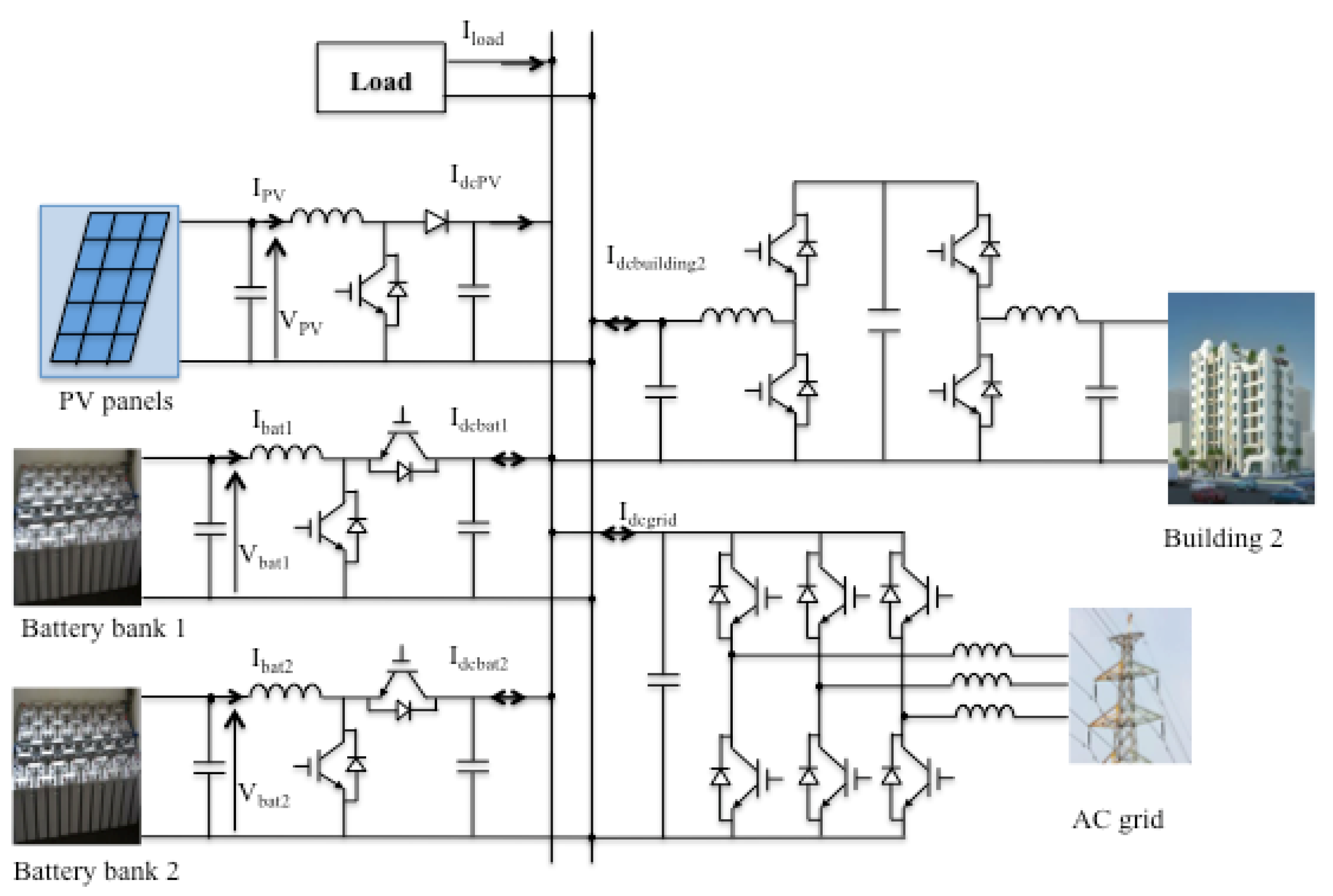
It is supposed that the layout of a DC microgrid supplying a building is configured as in Figure 2. This DC microgrid consists of PV panels mounted on the roof of the building, two battery banks, and DC loads. This grid is connected to the AC utility through a voltage source converter (VSC) and a nearby building via a split-pi converter. PV panels always operate at the maximum power point tracking (MPPT) mode to extract maximum energy from the Sun. The loads operate on their own merits. The objective of the operation strategy is always ensuring adequate power for the load while maintaining economical operation and system stability.
Sharing power between buildings in a neighborhood is implemented by controlling a split-pi converter, which always works as a current-controlled source (CCS). The battery storage systems (BESs) are important components to fulfill this control strategy. They can work in any of standby, charge, or discharge modes according to the condition operations. The capacities of batteries are selected such that it is capable of storing all surplus energy from the PV and efficiently supplying the DC load at low demand. Additionally, the exchanged power with the nearby buildings is also taken into account. In our study, droop control method is used to autonomously control sharing power between two BESs. The AC grid plays a backup role for the DC microgrid in critical cases when some power sources are cut off.
2.2. Control Strategy
All the terminals connected to the DC bus can be classified into two types: power terminals and slack terminals. Power terminals indicate the sources, which either supply or consume power to/from the DC bus on their merits, and usually do not contribute to the control voltage of the bus. The DC loads, PV panels working in MPPT mode, and nearby buildings are examples of power terminal sources. On the other hand, the function of slack terminal sources is to accommodate the power fluctuation caused by power terminals, and maintain power balance and stable voltage. BESs in voltage-controlled mode and VSCs are typical examples of slack terminals. Each operation mode needs at least one slack terminal to balance overall power. On the contrary, when there are multiple slack terminals, cooperation should be done to avoid any possible conflict among them.
The balance of power at any instant is expressed by the following equation:
where is the power generated by PV; is the total power injected into the bus from the BESs, which is positive when BESs are discharged and negative when BESs are charged; is the exchanged power with the close building; is the exchanged power with the AC grid. The sign of these powers are positive or negative belonging to the power direction entering or leaving the DC bus; is the power of the load.
This balance condition is guaranteed with the objectives of maximum renewable energy extraction, optimizing usages of BES, reducing energy imported from the AC grid, and maintaining bus voltage within the permitted range under the variation of the loads and sources. A three-level hierarchical control is proposed to achieve system reliability and economic operation.
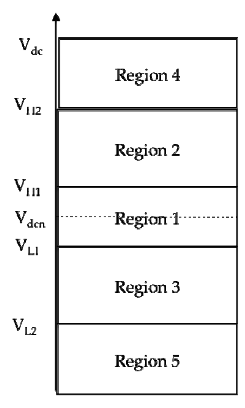
The operating range of DC-bus voltage is divided into five regions (see Figure 3), where Vdcn is the nominal voltage of the DC bus, VH2 and VL2 are the limits of the allowable voltage band of the DC microgrid, and VH1 and VL1 are the points of activating the battery charging and discharging, respectively.
Level 1: Stand-Alone Operation
The BESs play an importance role in controlling the balance of power within the microgrid. To ensure the secure and optimal operation of BESs, a control strategy based on state of change (SOC) and bus voltage is proposed in Figure 4.
Region 1: VL1 ≤ Vdcn ≤ VH1: The BESs operate in idle mode to avoid frequent battery charge/discharge. The powers from PV and building 2 (if applicable) are balanced with the load. Since there is no slack terminal, the bus voltage varies within region 1, corresponding to the change of load and PV power.
Region 2: VH1 ≤ Vdcn ≤ VH2: When the power generated from the PV is larger than load power, the bus voltage increases and falls into region 2. The batteries start charging to store surplus energy and regulate the bus voltage. The residual power can also be transmitted into a neighboring building. If BESs are charged to full state (SOC = SOCH), the batteries can no longer control the bus voltage, and the VSC is activated to switch the system into the grid-connected mode.
Region 3: VL2 ≤ Vdcn ≤ VL1: The deficiency of power in the system leads to a decrease in the bus voltage. BESs are discharged to compensate the deficient power in the system. In this condition, the microgrid can also receive power from building 2. When batteries reach limited discharge rate (SOCL), the VSC is switched from idle mode to control voltage mode at VL2, and the system consequently changes into grid-connected mode.
When the DC microgrid is working in regions 2 or 3, the surplus/deficient power can be stored/compensated by two BESs through DC–DC converters. In order to avoid the circular current loop, droop control method is used to adjust power sharing between BESs. The principle of the droop control method can be found in [12].
Level 2: Control Power Sharing between two BESs in Real-Time Operation
The limitation of control proposed in level 1 is the lack of a communication link that results in missing out on the optimization operation. The reason can be indicated hereafter. Firstly, droop resistances are calculated on the basis of the maximum permitted voltage deviation and maximum BES capacity, while instant voltage deviation and capacities of batteries are varying, which leads to errors in power sharing. Secondly, since the charging capability of BES depends on SOC and bus voltage, effect of SOC should be taken in account when estimating the value of droop resistance. Thirdly, in order to increase the lifetime of the batteries, one with higher SOC should be discharged faster and charged more slowly than that with lower SOC to prevent harm in extreme conditions.
The drawback in level 1 control can be solved by real-time information sharing between two converters of BESs. The real-time data, like bus voltage, power flows, and operation status of the converters, are monitored by the communication link and employed to make operation decisions. Therefore, the optimal cooperation between two BESs can be achieved. In level 2, the power sharing between two BESs is improved by adjusting the charging and discharging droop resistances of BESs based on the real-time SOC of BESs [13].
If SOC is higher than the average SOC of all BESs, the droop resistance will increase in comparison with the original value during charging state, and reduce during the discharging state, and vice versa. These promise that with higher SOC there will be smaller power charging, and larger power discharging.
Level 3: Grid-Connected Mode
In the case that there is a sudden loss of load or PV unit, over-voltage or under-voltage may occur, and the voltage will be out of permission range. This would lead to the instability of the system. To protect the DC microgrid under these abnormal conditions, it must be switched into the grid-connected mode.
In region 4 (Vdc > VH2) or region 5 (Vdc < VL2): when bus voltage reaches VH2 or VL2 values, the VSC is activated. Only the AC grid source works as a slack terminal to control the voltage of the DC bus.
3. Control Method of Converters
In order to implement the proposed hierarchical control scheme, each converter is controlled to perform a different mode of operation. The mode selection is determined by the mode selection signal, which is scheduled by hierarchical control strategy. The operating modes of PV, BESs, VSC, and the converter of building 2 are shown in Table 1.
Proportional-integral (PI) controllers are usually used in controlling the current and voltage of DC microgrids because of their zero steady-state error, their easily tuned coefficient and robustness.
3.1. PV Converter Control
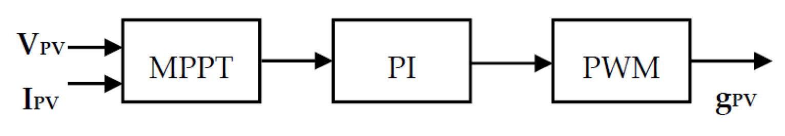
The PV converter always works in MPPT mode in order to extract maximum power from the PV source. Maximum power point tracking by incremental conductance method (INC) algorithm is used. The INC checks for the MPPT by comparing dI/dV against –I/V until it reaches the voltage operating point at which the incremental conductance is equal to the source conductance [28]. The control diagram of the PV converter is shown in Figure 5.
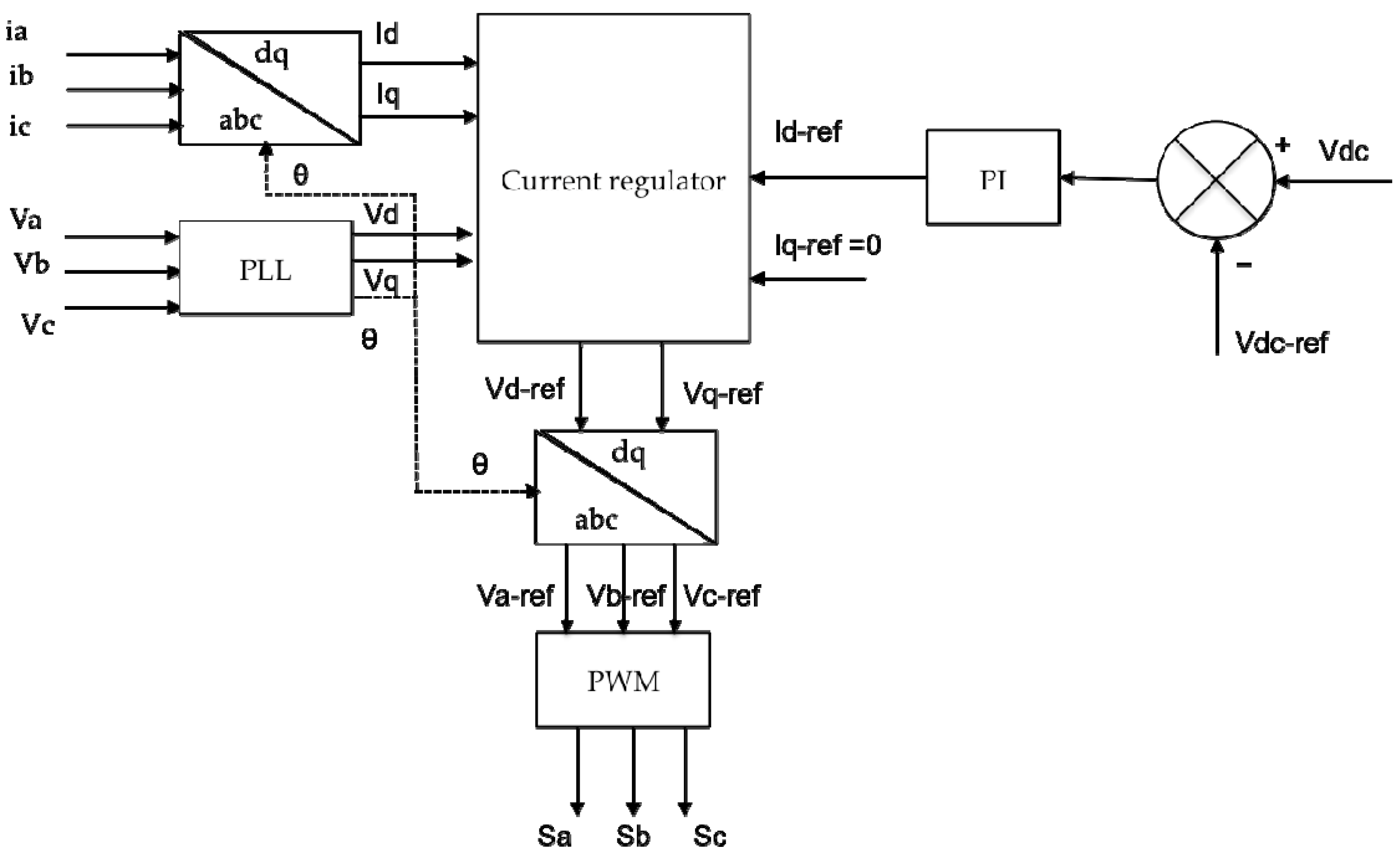
3.2. Grid-Side Inverter Control
The voltage-oriented control (VOC) method guarantees high dynamic and static performance, and is selected to drive the grid-connected converter. The decoupled control diagram of the converter is shown in Figure 6. It is composed of two control loops; i.e., outer loop for the DC voltage and inner loop for the converter output current [29].
3.3. Battery Converter Control
The battery control diagram is shown in Figure 7. The droop voltage reference and droop resistance are calculated. This voltage is compared with DC bus voltage to obtain the control signal. Two PI controllers, including a fast inner PI current controller and a slow outer voltage controller, are used to ensure that both output voltage and current are regulated. The current is limited in the range of Ibat_max and Ibat_min in the control loop to avoid overcurrent during charging and discharging operation.
3.4. Control of Converter Connected to Building 2
The converter connected to building 2 only works when both building 1 and building 2 have demand of exchanging power (i.e., building 1 is in the shortage of power, while building 2 is in the surplus of power, or vice versa). The allowable transmitted power is shown as Iref. The direction of power flow is consequently determined based on the sign of Iref. This current is compared with the measurement at the DC-bus site to generate the control signal. The controlled block is displayed in Figure 8.
4. Simulation Results and Discussion
4.1. System Description
A simulation was implemented in Matlab/Simulink to verify the operation of the proposed DC microgrid and control strategy, in the following conditions:
The nominal voltage of DC bus Vdcn was set at 500 V; VH1 and VL1 were ±1% Vdcn, respectively, while VH2 and VL2 was ±5% Vdcn, respectively.
Thus, VH1 = 505 V; VH2 = 525 V; VL1 = 495 V; VL2 = 475 V.
A typical load curve of the office building had a peak of 16 kW, as can be seen in Figure 9a.
A model of a PV panel was built in the Matlab/Simulink environment based on the commercial model SunPower-SPR-305-WHT. The rated power of the PV was 20 kW peak. The parameters of these PV panels are displayed in Table 2. Data of a typical daily irradiance in Lyon was used to simulate the operation of the PV system, see Figure 9b.
The model of a Lithium-Ion battery in Matlab/Simulink was used. The rated parameters are provided in Table 3. Two BESs (BES1 and BES2) are supposed to have similar rated power and type, but different initial SOCs of 50% and 70% for BES1 and BES2, respectively.
4.2. Simulation Results and Discussion
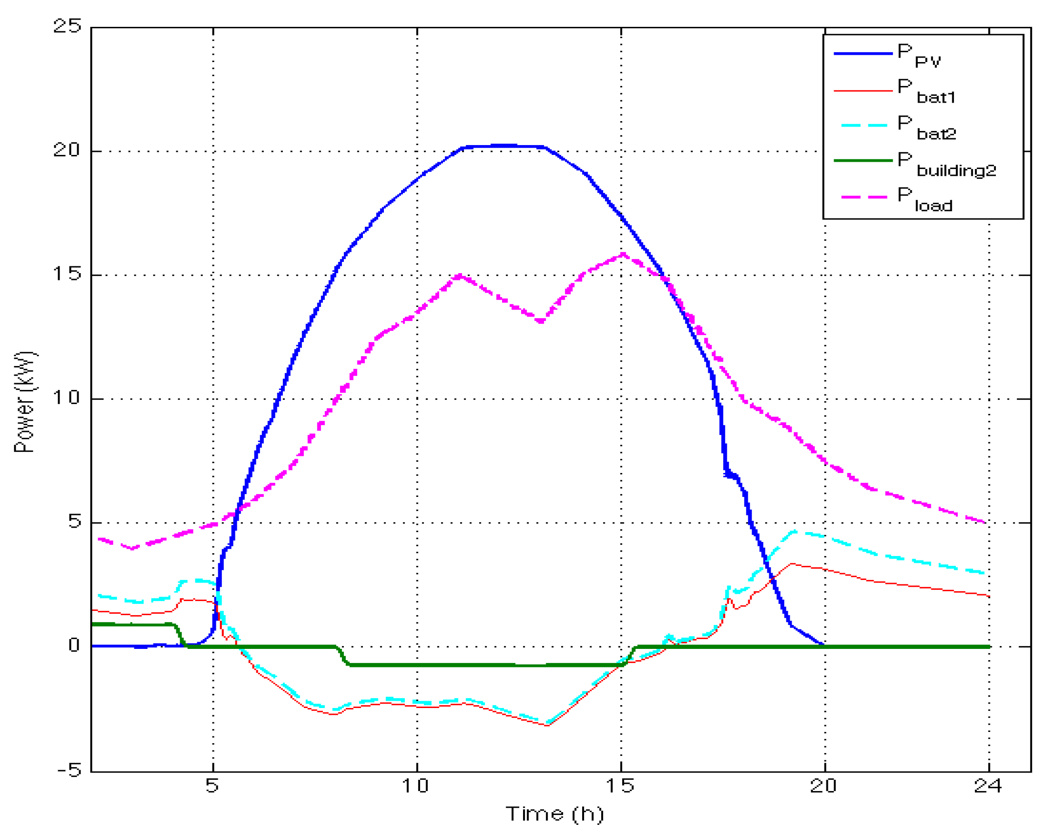
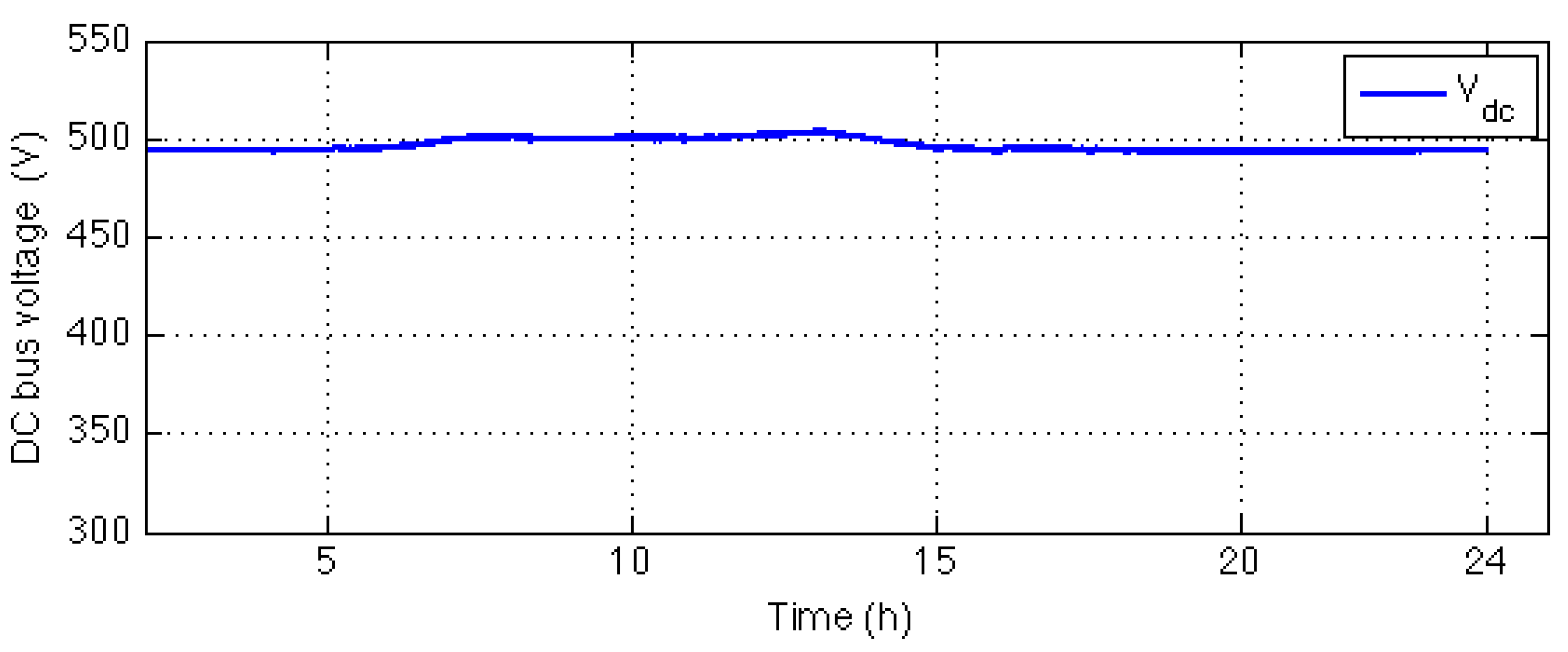
The operation of the proposed DC microgrid in level 1 and level 2 hierarchical control is illustrated in Figure 10 and Figure 11. Figure 10 shows the power sharing among sources to meet a daily load demand. The variation of DC-bus voltage is displayed in Figure 11. It can be seen that the power of PV panels (the blue line) varies according to the daily irradiance. This power is equal to zero at night and reaches the peak of 20 kW at noon. It is supposed that building 2 supplied 0.9 kW for the grid during the period from 0 am to 4 am and received the same amount power between 8 am and 3 pm (the green line). The magenta line stands for load curve, which is described in Figure 9a. The red line is the power of BES 1, and the cyan line presents BES 2 power.
During the period from 6 am to 4 pm, the PV power is higher than the load power, which results in the increase of DC-bus voltage. The two BESs are charged to absorb the residual power. BES2 has higher SOC (70%), and is charged with lower power. A part of the surplus power is exchanged to building 2, with the benefit of avoiding the overcharge of BESs. The bus voltage increases to a level larger than nominal voltage. However, this voltage is smaller than VH1 due to the effect of droop method. During the evening and night, the load power decreases, and there is no PV power, leading to the shortage of the power. As a result, the bus voltage reduces and the BESs are switched to the discharging mode to supply power to the load. The discharging power of BES from 0 am to 4 am is smaller than that between 4 pm and midnight because of the exchanged power with building 2. The BES 2 was discharged with higher power than BES1, because of higher SOC. Although the bus voltage is decreased and less than nominal voltage, its value is still maintained in the allowable range. Since the power of PV and building 2 were sufficient to manage the load, the grid-side converter does not work in this simulation scenario. These simulation results completely accord with the previously presented control strategy.
5. Conclusions
A hierarchical control strategy is proposed for the optimal and stable operation of a DC microgrid of buildings in a meshed distributed system. Power flows in the meshed grid are controlled using split-pi converters. The autonomous control scheme and the accuracy of power sharing among batteries according to the change of SOC are obtained. Furthermore, the emergency conditions are managed by the AC grid. In this way, renewable energy sources always work in MPPT mode, even under extreme conditions without load shedding or reducing the power of PV. The capacity of the battery can be reduced thanks to exchanged power with nearby DC microgrids. The reliability of the system will be further improved if the DC microgrids of the buildings are integrated with each other.
However, the drawback of this method is that the frequent charging or discharging of battery system results in reduced lifetime. Reducing the working time or increasing the lifetime of batteries—which will be in an upcoming study—could improve the efficiency of the control strategy.
Acknowledgments
We would like to thank Glink project, Erasmus Mundus program has been funding for this study.
Author Contributions
The study was performed and written by Thi Thuong Huyen Ma. Other authors are academic supervisors. All the authors contributed to setting up the layout, detail contents and revising this manuscript. The simulation part was carried out by Thi Thuong Huyen Ma under the supervision of Hoang Giang Vu and Hamed Yahoui. All authors have read and approved the manuscript.
Conflicts of Interest
The authors declare no conflict of interest and the founding sponsors had no role in the design of the study; in simulation; in the writing and the decision to publish this manuscript.
References
- Torcellini, P.; Pless, S.; Deru, M; Crawley, D. Zero Energy Buildings: A Critical Look at the Definition; Preprint. In Proceedings of the 2006 ACEEE Summer Study on Energy Efficiency in Buildings, Pacific Grove, CA, USA, 13–18 August 2006; 2006; p. 15. [Google Scholar]
- Justo, J.J.; Mwasilu, F.; Lee, J.; Jung, J.W. AC-microgrids versus DC-microgrids with distributed energy resources: A review. Renew. Sustain. Energy Rev. 2013, 24, 387–405. [Google Scholar] [CrossRef]
- Kakigano, H.; Miura, Y.; Ise, T.; Momose, T.; Hayakawa, H. Fundamental characteristics of DC microgrid for residential houses with cogeneration system in each house. In Proceedings of the IEEE Power and Energy Society General Meeting—Conversion and Delivery of Electrical Energy in the 21st Century, Pittsburgh, PA, USA, 20–24 July 2008; pp. 1–8. [Google Scholar]
- Rodriaguez-Otero, M.A.; O’Neill-Carrillo, E. Efficient home appliances for a future DC residence. In Proceedings of the 2008 IEEE Energy 2030 Conference, Atlanta, GA, USA, 17–18 November 2008; pp. 1–6. [Google Scholar]
- Panbao, W.; Wei, W.; Dianguo, X.; Guihua, L.; Ming, L. An autonomous control scheme for DC micro-grid system. In Proceedings of the IECON 2013—39th Annual Conference of the IEEE Industrial Electronics Society, Vienna, Austria, 10–13 November 2013; pp. 1519–1523. [Google Scholar]
- Wunder, B.; Ott, L.; Kaiser, J.; Han, Y.; Fersterra, F.; Marz, M. Overview of different topologies and for DC micro grids. In Proceedings of the 2015 IEEE First International Conference on DC Microgrids (ICDCM), Atlanta, GA, USA, 7–10 June 2015; pp. 349–354. [Google Scholar]
- Hu, R.; Weaver, W.W. Dc microgrid droop control based on battery state of charge balancing. In Proceedings of the 2016 IEEE Power and Energy Conference at Illinois, Urbana, IL, USA, 19–20 February 2016; pp. 1–8. [Google Scholar]
- Lee, J.; Han, B.; Choi, N. DC micro-grid operational analysis with detailed simulation model for distributed generation. In Proceedings of the 2010 IEEE Energy Conversion Congress and Exposition, Atlanta, GA, USA, 12–16 September 2010; pp. 3153–3160. [Google Scholar]
- Zhang, L.; Wu, T.; Xing, Y.; Sun, K.; Gurrero, J.M. Power control of DC microgrid using DC bus signaling. In Proceedings of the 2011 Twenty-Sixth Annual IEEE Applied Power Electronics Conference and Exposition (APEC), Fort Worth, TX, USA, 6–11 March 2011; pp. 1926–1932. [Google Scholar]
- Zhao, J.; Dörfler, F. Distributed control and optimization in DC microgrids. Automatica 2015, 61, 18–26. [Google Scholar] [CrossRef]
- Lonkar, M.; Ponnaluri, S. An overview of DC microgrid operation and control. In Proceedings of the 2015 6th International Renewable Energy Congress (IREC), Sousse, Tunisia, 24–26 March 2015. [Google Scholar]
- Chi, J.; Wang, P.; Xiao, J.; Tang, Y.; Choo, F.H. Implementation of Hierarchical Control in DC microgrids. IEEE Trans. Ind. Electron. 2014, 61, 4032–4042. [Google Scholar]
- Huang, P.H.; Xiao, W.; El Moursi, M.S. A practical load sharing control strategy for DC microgrids and DC supplied houses. In Proceedings of the IECON 2013—39th Annual Conference of the IEEE Industrial Electronics Society, Vienna, Austria, 10–13 November 2013; pp. 7124–7128. [Google Scholar]
- Xu, L.; Chen, D. Control and operation of a DC microgrid with variable generation and energy storage. IEEE Trans. Power Deliv. 2011, 26, 2513–2522. [Google Scholar] [CrossRef]
- Chen, D.; Xu, L. DC microgrid with variable generations and energy storage. In Proceedings of the IET Conference on Renewable Power Generation (RPG 2011), Edinburgh, UK, 6–8 September 2011; pp. 1–6. [Google Scholar]
- Guerrero, J.M.; Vasquez, J.C.; Matas, J.; de Vicuna, L.G.; Castilla, M. Hierarchical Control of Droop-Controlled AC and DC Microgrid: A General Approach toward Standardization. IEEE Trans. Ind. Electron. 2011, 58, 158–172. [Google Scholar] [CrossRef]
- Dragicevic, T.; Lu, X.; Vasquez, J.C.; Guerrero, J.M. DC Microgrids—Part I: A Review of Control Strategies and Stabilization Techniques. IEEE Trans. Power Electron. 2016, 31, 4876–4891. [Google Scholar] [CrossRef]
- Schonberger, J.; Duke, R.; Round, S.D. DC-Bus Signaling: A Distributed Control Strategy for a Hybrid Renewable Nanogrid. IEEE Trans. Ind. Electron. 2006, 53, 1453–1460. [Google Scholar] [CrossRef]
- Sun, K.; Zhang, L.; Xing, Y.; Guerrero, J.M. A Distributed Control Strategy Based on DC Bus Signaling for Modular Photovoltaic Generation Systems with Battery Energy Storage. IEEE Trans. Power Electron. 2011, 26, 3032–3045. [Google Scholar] [CrossRef]
- Zhong, Q.; Member, S. Robust Droop Controller for Accurate Proportional Load Sharing Among Inverters Operated in Parallel. IEEE Ind. Electron. Soc. 2013, 60, 1281–1290. [Google Scholar] [CrossRef]
- Vandoorn, T.L.; De Kooning, J.D.M.; Meersman, B.; Guerrero, J.M.; Vandevelde, L. Automatic power-sharing modification of P/V droop controllers in low-voltage resistive microgrids. IEEE Power Energy Soc. 2012, 27, 2318–2325. [Google Scholar]
- Shafiee, Q.; Dragicevic, T.; Vasquez, J.C.; Guerrero, J.M. Hierarchical control for multiple DC-microgrids clusters. In Proceedings of the 2014 IEEE 11th International Multi-Conference on Systems, Signals & Devices (SSD), Barcelona, Spain, 11–14 February 2014; pp. 1–6. [Google Scholar]
- Gonzalez-longatt, F.; Rajpurohit, B.S.; Singh, S.N. Optimal Structure of a Smart DC micro-grid for a Cluster of Zero Net Energy Buildings. In Proceedings of the 2016 IEEE International Energy Conference (ENERGYCON), Leuven, Belgium, 4–8 April 2016; pp. 1–7. [Google Scholar]
- Riccobono, A.; Ferdowsi, M.; Hu, J.; Wolisz, H.; Jahangiri, P.; Muller, D.; De Doncker, R.W.; Monti, A. Next generation automation architecture for DC smart homes. In Proceedings of the 2016 IEEE International Energy Conference (ENERGYCON), Leuven, Belgium, 4–8 April 2016. [Google Scholar]
- Wunder, B.; Ott, L.; Szpek, M.; Boeke, U.; Weis, R. Energy efficient DC-grids for commercial buildings. In Proceedings of the 2014 IEEE 36th International Telecommunications Energy Conference (INTELEC), Vancouver, BC, Canada, 28 September–2 October 2014; pp. 1–8. [Google Scholar]
- Celli, G.; Pilo, F.; Pisano, G.; Allegranza, V.; Cicoria, R.; Iaria, A. Meshed vs. radial MV distribution network in presence of large amount of DG. In Proceedings of the IEEE PES Power Systems Conference and Exposition, New York, NY, USA, 10–13 October 2004; pp. 709–714. [Google Scholar]
- Ma, T.T.H.; Yahoui, H.; El Boubkari, F.B.; Morel, H.; Vu, H.G.; Siauve, N. Building a Matlab/Simulink Model of a SiC-JFET for the investigation of Solid State DC Breaker. In Proceedings of the International conference on Components and Systems for DC grids (COSYS-DC 2017), Grenoble, France, 14–15 March 2017. [Google Scholar]
- Rashid, M.H. Power Electronics Handbook Devices, Circuits, Applications, 2nd ed.; Elsevier Inc.: Amsterdam, The Netherlands, 2007. [Google Scholar]
- Pena, R.; Clare, J.C.; Asher, J.M. Doubly fed induction generator using back-to-back PWM converters and its application to variable-speed wind-energy generation. IEE Proceedings-Electric Power Applications 1996, 143, 231–241. [Google Scholar] [CrossRef]
Figure 1.
The layout of a mesh DC microgrid in a neighborhood.
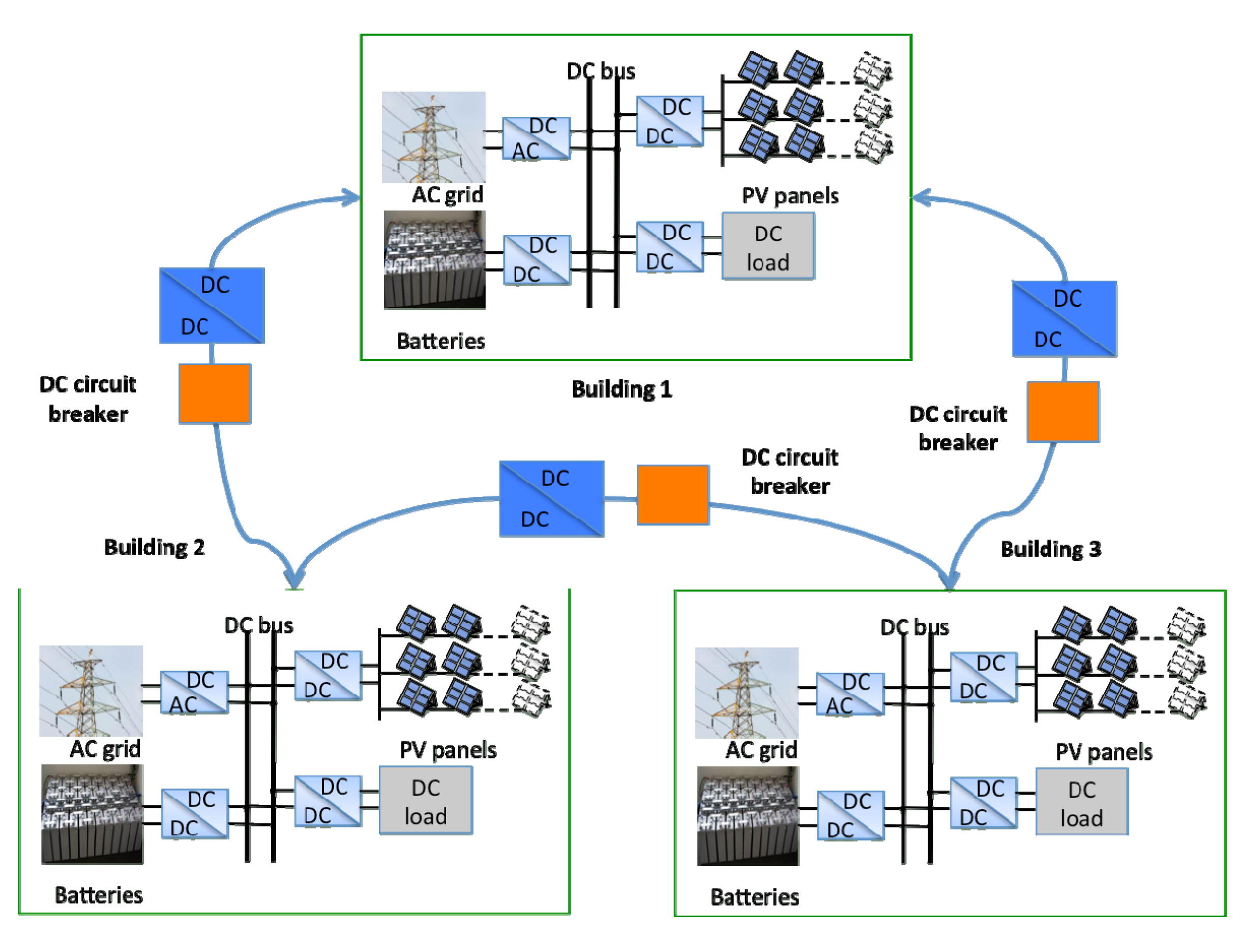
Figure 2.
DC microgrid configuration of a building.

Figure 3.
Operation regions of DC bus voltage.

Figure 4.
Battery controlled strategies. SOC: state of charge; VSC: voltage source converter.
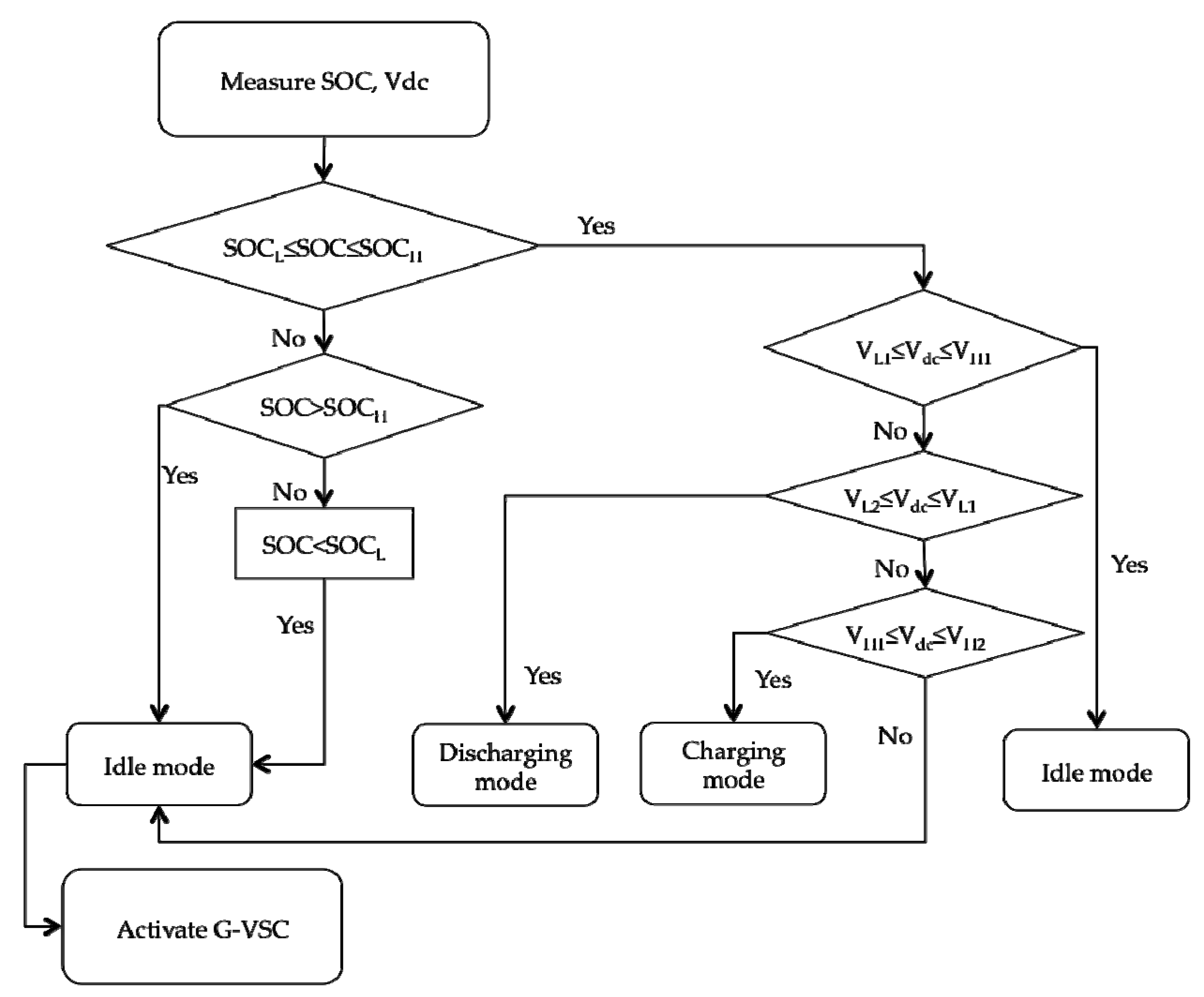
Figure 5.
Control diagram of the PV converter. PI: proportional-integral; PWM: pulse width modulation.
Figure 5.
Control diagram of the PV converter. PI: proportional-integral; PWM: pulse width modulation.

Figure 6.
Control diagram of the grid-side inverter, PLL: phase-locked loop.

Figure 7.
Control diagram of battery converter.
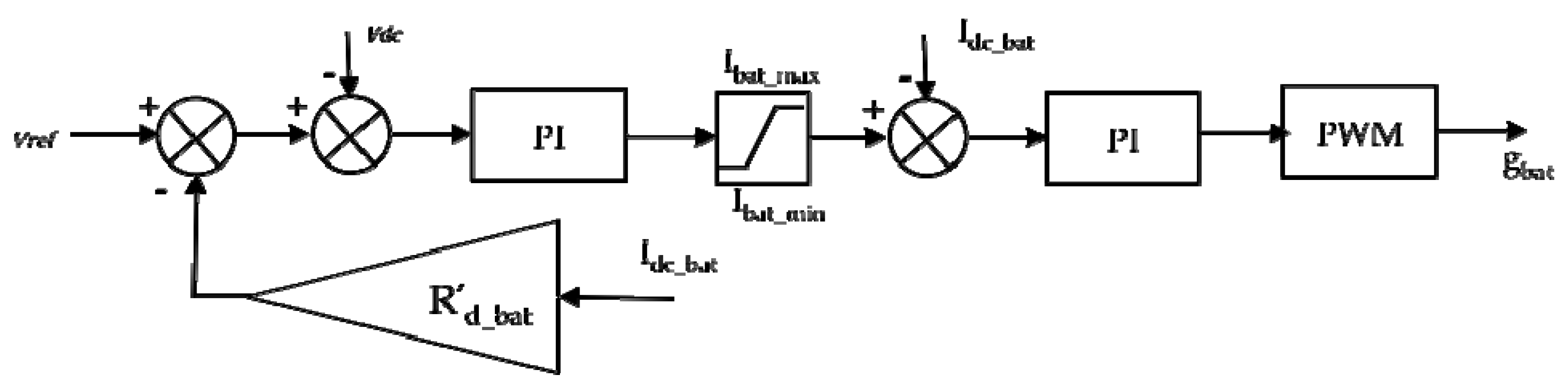
Figure 8.
Control diagram of converter connected to building 2.
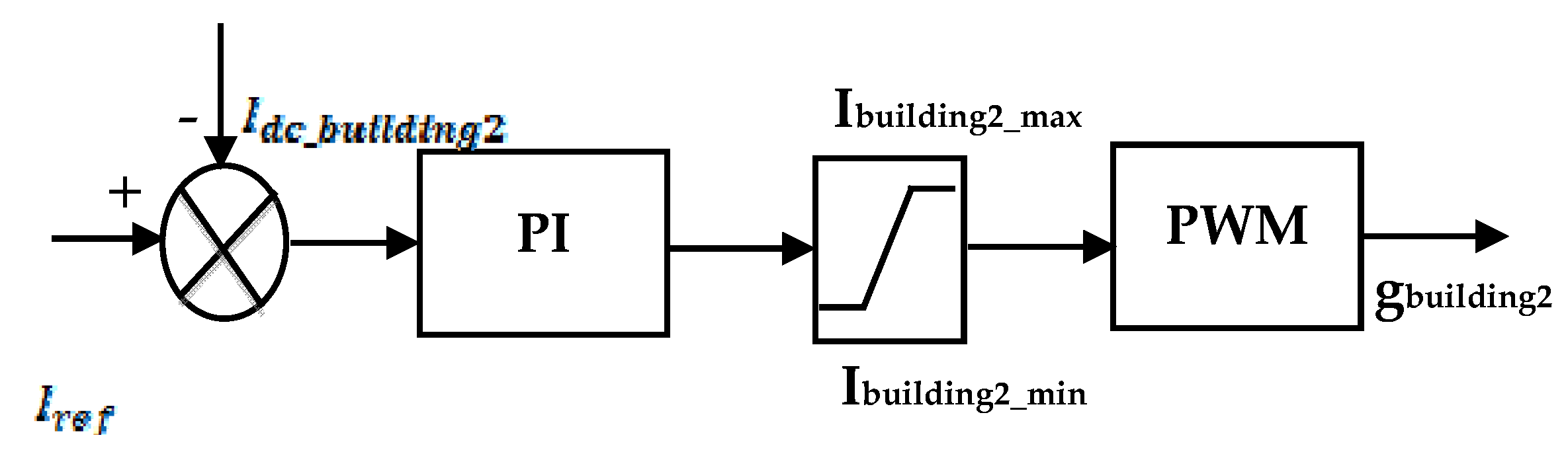
Figure 9.
(a) Daily typical load curve of an office; (b) Daily typical irradiance.
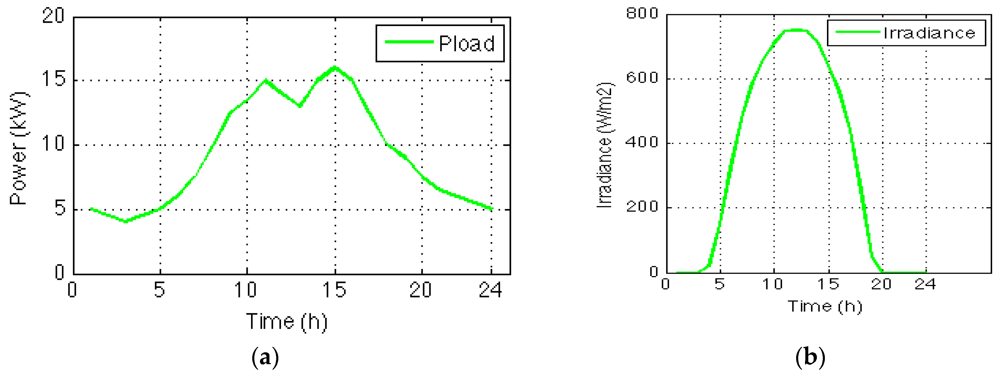
Figure 10.
DC microgrid configuration of a building.

Figure 11.
DC bus voltage.


Table 1.
Operation modes of converters. CCS: current-controlled source; CVS: controlled voltage source; MPPT: maximum power point tracking.
Table 1.
Operation modes of converters. CCS: current-controlled source; CVS: controlled voltage source; MPPT: maximum power point tracking.
| 1 | 2 | 3 | 4 | |
| MPV | MPPT | MPPT | MPPT | MPPT |
| M building2 | CCS1 | CCS1 | CCS1 | CCS1 |
| MBESs | Idle | CVS | Idle | CCS |
| MVSC | Idle | Idle | CVS | CVS |
1 If applicable.
Table 2.
Parameters of PV panels.
| Parameter | Value | Unit |
|---|---|---|
| Number of cells of one panel | 96 | - |
| Number of parallel panels | 18 | - |
| Number of series panels | 5 | - |
| Rated power | 20 | kW |
Table 3.
Parameters of Lithium-Ion battery.
| Parameter | Value | Unit |
|---|---|---|
| Number of series batteries in a bank | 200 | - |
| Number of parallel banks | 20 | - |
| Nominal voltage | 236 | V |
| Rated discharging current | 27.8 | A |
| Rated power | 6.56 | kW |
| Rated capacity | 130 | Ah |
© 2017 by the authors. Licensee MDPI, Basel, Switzerland. This article is an open access article distributed under the terms and conditions of the Creative Commons Attribution (CC BY) license (http://creativecommons.org/licenses/by/4.0/).
Share and Cite
MDPI and ACS Style
Ma, T.T.H.; Yahoui, H.; Vu, H.G.; Siauve, N.; Morel, H. A Control Strategy of DC Building Microgrid Connected to the Neighborhood and AC Power Network. Buildings 2017, 7, 42. https://doi.org/10.3390/buildings7020042
AMA Style
Ma TTH, Yahoui H, Vu HG, Siauve N, Morel H. A Control Strategy of DC Building Microgrid Connected to the Neighborhood and AC Power Network. Buildings. 2017; 7(2):42. https://doi.org/10.3390/buildings7020042
Chicago/Turabian StyleMa, Thi Thuong Huyen, Hamed Yahoui, Hoang Giang Vu, Nicolas Siauve, and Hervé Morel. 2017. "A Control Strategy of DC Building Microgrid Connected to the Neighborhood and AC Power Network" Buildings 7, no. 2: 42. https://doi.org/10.3390/buildings7020042
Note that from the first issue of 2016, this journal uses article numbers instead of page numbers. See further details here.