1. Introduction
1.1. Challenges with Structural Glass
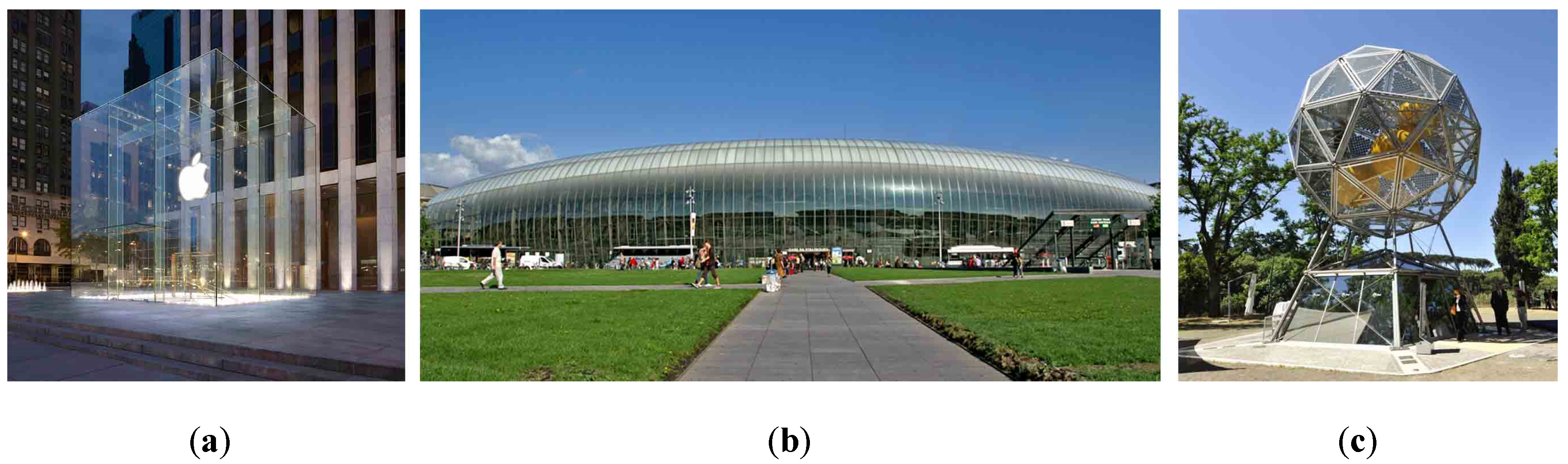
In the past century, glass has become a structural material thanks to the vision of some outstanding designers. First used only in secondary building elements, such as infill window panels, glass gradually moved to the main load bearing structural elements such as columns, beams, slabs, curtain walls, facades, and roofs [
1,
2]. Presently, its use is suitable for many architectural purposes. For new construction, the iconic character of glazed components allows transparency, daylight, and visual lightness. The attraction of people’s interest and the characterization of a site is sometimes made possible simply by means of transparent basic geometries [
3] (
Figure 1a). For renovation projects or in presence of artefacts of high historic and artistic value, a modern transparent skin can wrap existing buildings, consequently increasing the energetic performance and creating new spaces [
4] (
Figure 1b). Glass denotes a recognizable lightweight intervention, preserving visual contact with the pre-existing structure and conferring upon it a modern appearance. For high-tech components, a further advantage is the possibility offered by laminated glass panels to embed devices in the interlayer substrate. As a result, glass can host new functions such as power generation, solar shading, or image or text transmission thanks to PV cells, luminescent systems, sensors, and programmable cells. The Diamante trigenerative power station symbolizes the efficiency of such integrated design: glass-embedded PV cells lying on the icosahedron-shaped structure are able to meet the energy demand of the public lighting system of the Parco del Pratolino in Florence, Italy [
5] (
Figure 1c).
Contemporary architectural needs, brittle failure modality, and scarce random tensile resistance make glass unsuitable for challenging uses for overcoming long spans. Therefore, it is necessary to mechanically connect glass panes with metallic or, in general, ductile elements in order to create hybrid components [
6]. Herein, the metallic reinforcement plays a double role. First, it works as a steel bar in the cracked reinforced concrete, or rather contributes in closing the cracks. Second, it avoids the brittle sudden failure of the element (passive reinforced glass elements [
7]). If the metallic component is further pre-stressed, a beneficial pre-compression is established on glass, and its apparent tensile resistance is increased (active reinforced glass elements).
Research and experimental activities emphasize the advantages of adopting hybridism. In particular, active pre-stressed beams showed excellent performance: these include beams with a single [
8,
9] or double [
10] glass web reinforced with external tendons, beams with metallic reinforcement adhesively [
11,
12,
13] or mechanically [
14] bonded at the bottom side, and two-sided reinforced glass beams [
15,
16]. Concerning two-dimensional systems, hybrid solutions are less diffuse than hybrid beams even though glass as a shear frame restraint has been used since the nineteenth century (i.e. in greenhouses). Indeed, the performances of shear walls were extensively investigated in [
17,
18,
19]. More recently, some researchers used glass panels to stiffen a steel framework [
20] and as hybrid shear walls by the adhesive bonding [
21] or friction connecting [
22] of a glass pane to a wooden frame. A substantial lack of planar or spatial hybrid pre-stressed constructional systems is observed to date, and therefore a globally high-redundant hybrid system to tackle the challenge of transparent long spans is missing.
1.2. Background and Scope of the Present Research
Among the research concerning hybrid glass systems, Travi Vitree Tensegrity (TVT) active reinforced beams were developed and patented at the University of Pisa. In TVT beams [
23,
24], the rules of Fail-Safe Design (FSD) [
25] were used in the conception and design of their structural behavior. In addition to hybridism and pre-compression, TVTs adopt the principle of segmentation of the entire structural assembly. The structural integrity of the latter is guaranteed only by mutual pre-stressing. Even though radically differing from conventional monolithic beams [
26], TVTs reached long spans comparable to those of competing metallic trusses.
The components in the TVTs are doubled and hierarchically calibrated both at local level and at the element level. The latter achieves a ductile behavior. At the Ultimate Limit State (ULS), a global ductile behavior is achieved through crisis by steel bars yielding to precede the buckling failure of the glass panel. At the Serviceability Limit State (SLS), once the glass panels decompression is exceeded, the detachment of the panel vertices from the nodes prevents the opening of cracks. The glass is loaded mostly by compression and shear stresses, thus matching the specific mechanics of the material. The use of laminated panels complies with the FSD: its quasi-ductile crisis avoids a sudden accidental collapse [
27,
28].
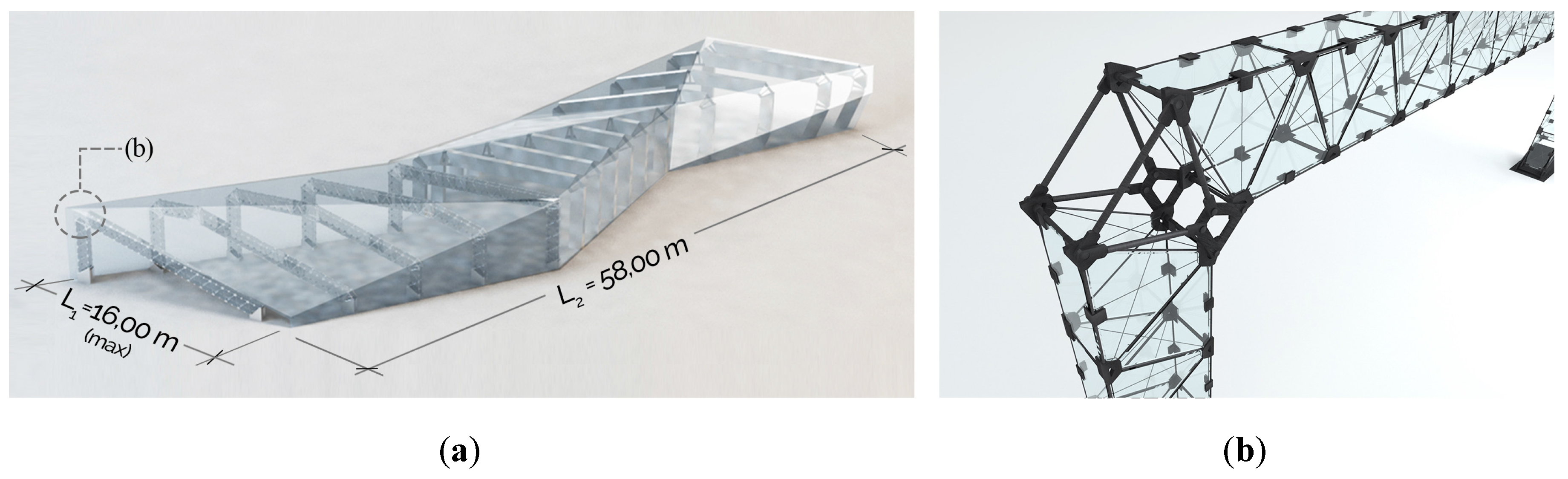
The intent to extend the use of TVT system in three-dimensional space and to design an iconic, sustainable, and modular pavilion led to the design of the pilot project of the Energy Gallery [
29] (
Figure 2). Architectural, energetic, and comfort requirements guided the form finding process of the pavilion; consequently, an adaptive structural solution was researched to allow different roof slopes. Because of the longitudinal development of the building, a standardised adaptive TVTγ frame portal was adopted, which was able to follow variations of heights and plan shape. The TVTγ is the third constructional system and was based on TVT principles. The previous two were the TVTα (designed and experimentally validated on a 2970 mm free span) and the TVTβ (designed and experimentally validated on a 3330 mm free span). With the structural and constructional expedients of the TVTγ, a long-spanned 12 m prototype was successfully built at the Structural Laboratory of the University of Pisa. The test-observed data are collected in [
23,
24].
Each frame portal of the Energy Gallery is made of three or four variously inclined TVTγ beams. The connection between their end nodes is realised by an adaptive joint system, which is made of tubular rods fastened at sleeves. Since all the frame portals had a considerable in-plane strength and stiffness, telescopic hollow steel beams connect each portal with the neighbouring one to assure lateral stability. Those steel tubes support outer glass panels, which act simply as claddings. In order to meet challenging contemporary glass architecture tendencies and to cover wider spaces with a transparent system and to bridge the existing research gap, the Energy Gallery structural system was advanced by defining a new design model, consisting of the following innovations:
The introduction of a 20 m spanned TVTγ-bis frame portal, derived from the previous TVTγ, with the substitution of the pre-stressed bars with strands. As an effect the transparency, the ULS strength and ductility are increased;
Simplification and de-materialization of the steel connections (beam-to-column joint and column-to-base joint) in order to excel both the transparency level and the mechanical performances;
Use of an innovative longitudinal transparent and diffuse bracing system, constituted by hybrid pre-compressed modular glass panels.
Thus, the objective of the present work is to demonstrate the architectural, the structural, and the technical feasibility of such a long-spanned glazed pavilion (TVT Pavilion). The theoretical study of mechanical behavior follows a multi-level approach, from local to global. A geometric and structural description of the pavilion and its components is provided. FEM modelling works and their relative main results are shown and commented on.
2. Design Principles and Assembly of the TVT Pavilion
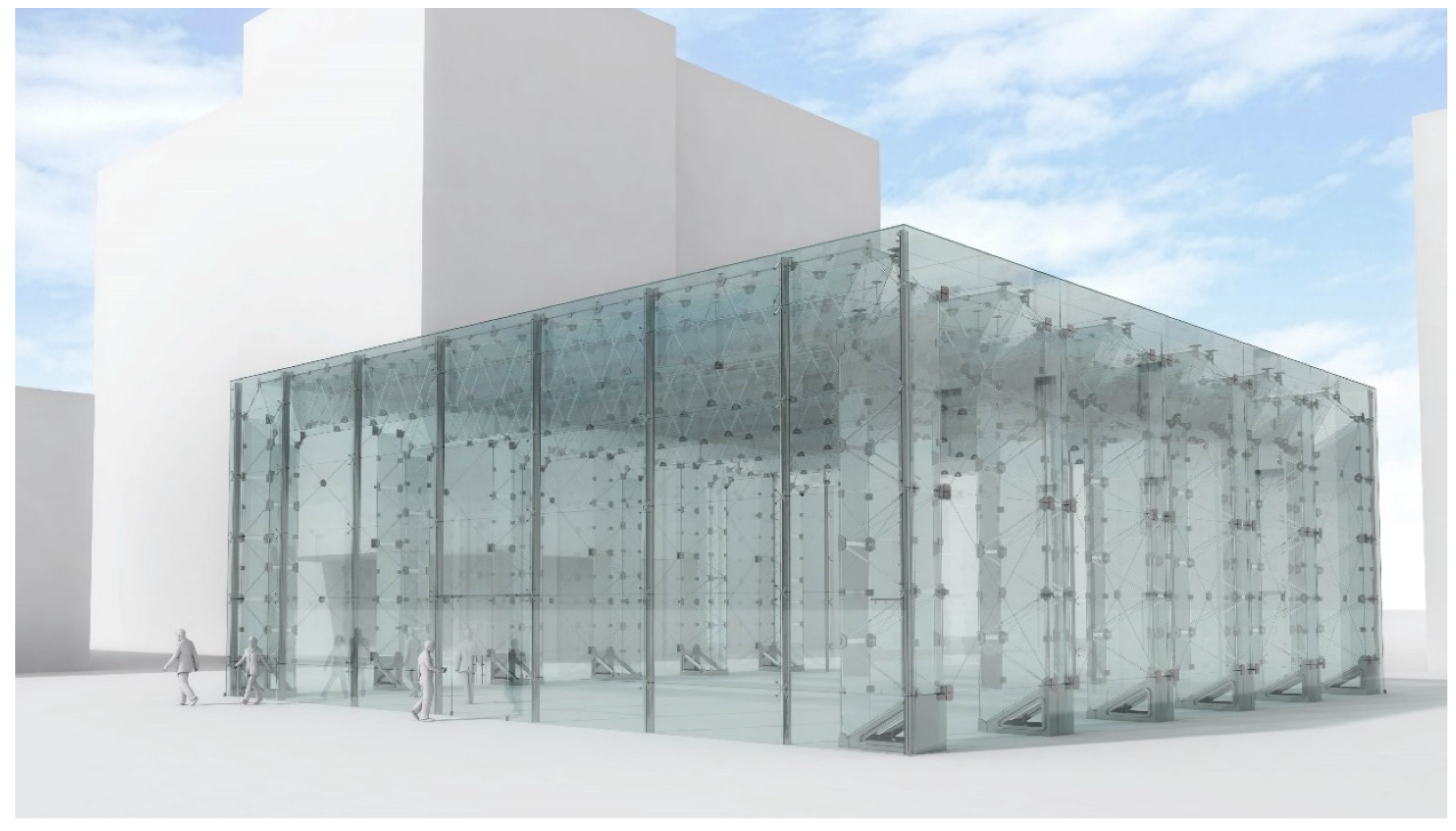
The TVT Pavilion is a parallelepiped-shaped building with a rectangular base of about 450 m
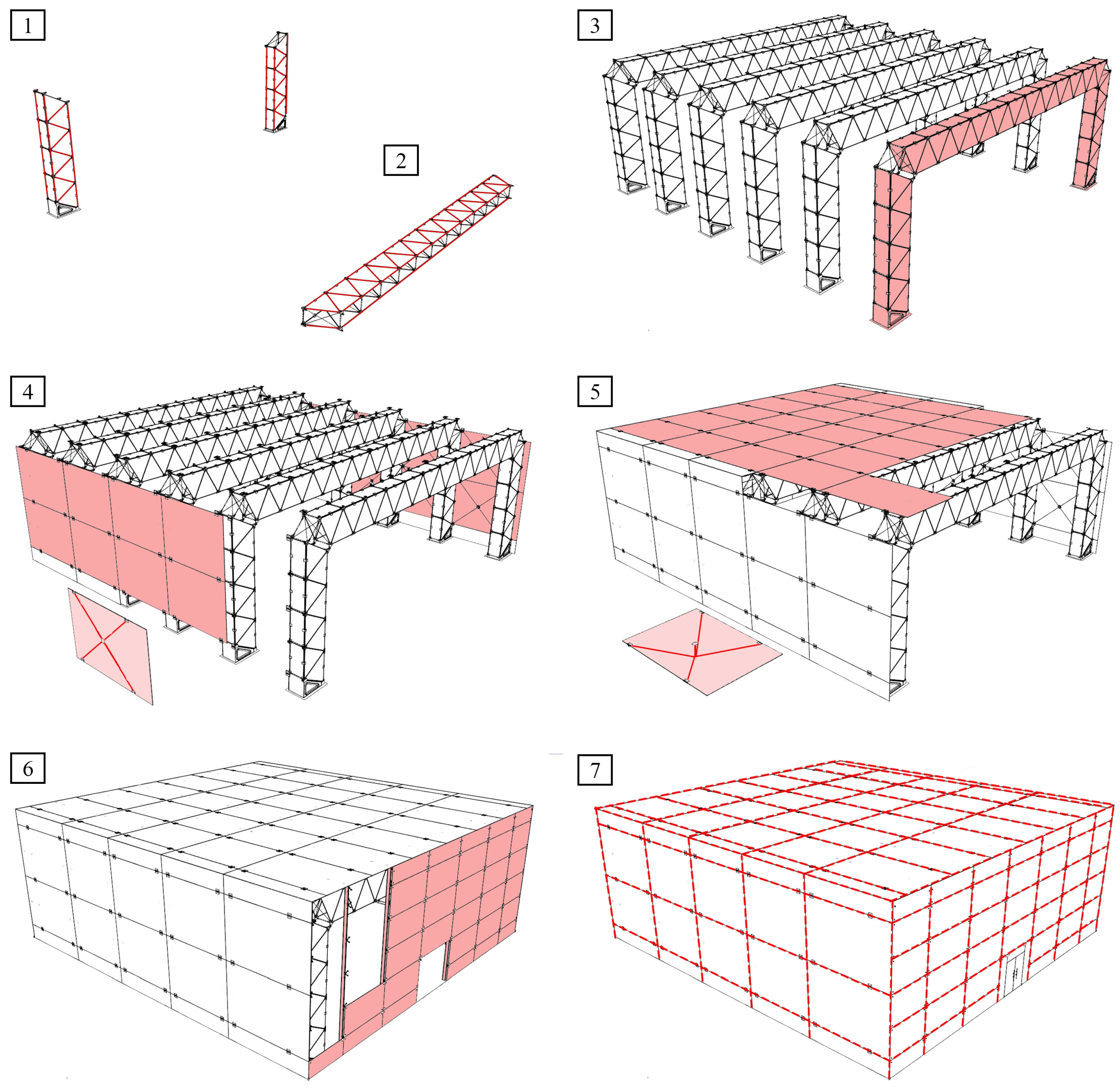
2 (21,940 mm × 20,595 mm) and 8076 mm in height. The whole glass skin is supported by six Warren-like portal frames of 20,395 mm span, longitudinally spaced by 4300 mm. Therefore, the main structural elements of the TVT Pavilion are the transversal portal frames, the hybrid bracing system (walls and roof), and the front and back façades (
Figure 3). The TVT pavilion adopts the same principles of the TVTs, with advantages at the ULS and at the SLS confirmed by numerous experimental outcomes [
18,
19]. The installation sequence of the TVT Pavilion shall be conducted in accordance to the following steps (
Figure 4):
Positioning of the pillars and their pre-compression. Outer, inner, and diagonal strands are pre-stressed with a different load rate to foster a quasi-isotropic compressive stress field on the glass panel. The aim is to reduce the possibility of traction force acting on glass, which arises only if its rate is higher than the compression stress value.
On-site assembly and pre-compression of the beams. The system is assembled on a horizontal plane in order to neglect the effect of dead loads. The purpose is to pre-stress the strands with different rates to produce a positive curvature opposite to the deflection of the structure due to its own weight and part of the live loads.
Installation of the beams on top of the pillars. The extremities’ nodes of the beams and the top of the column are fixed through the corner joinery system.
Installation of the vertical panels of the bracing system. The panes are prior pre-compressed on-site.
Installation of the horizontal panels of the roof bracing system. The panes are first pre-compressed on-site in order to counteract the deflection due to gravitational loads.
Façades assembly. The aluminium mullions are fastened to the frame portals’ nodes and ground connected, then the glass panels are placed.
All the glass panels are then equipped with waterproofing edge sealants.
3. Materials and Description of the Main Components of the Structural System
3.1. Materials
The selection of the materials complies with the mechanical performances expected from the building at ULS and SLS, as well as with the principles of FSD. Moreover, even non-structural functions are considered. The materials used in the design of the TVT Pavilion are shown in
Table 1.
The design values for the strands are referred to the Pr EN 10138-3 [
30]. The Young’s modulus considered in the following models is E = 201,000 N/mm
2.
In the nodes of the TVTγ-bis and at the recesses of the bracing panels, connections are neither bolted nor glued. In both cases, suitable aluminium spacers were designed in order to avoid tension peaks at the interface between steel and glass. A 2 mm thick EN AW 6060 T5 aluminium alloy was used [
31] with almost the same Young’s modulus of glass.
A commercial laminated PVB was designed as an interlayer for the laminated glass panels. The panes of HS glass are glued by means of a 1.52 mm thick PVB foil. In the present study, the shear resistance of the interlayer is neglected because the mechanical properties depend on the load duration and temperature. According to the [
32] the strength of glass is calculated as,
3.2. TVT Frame portal
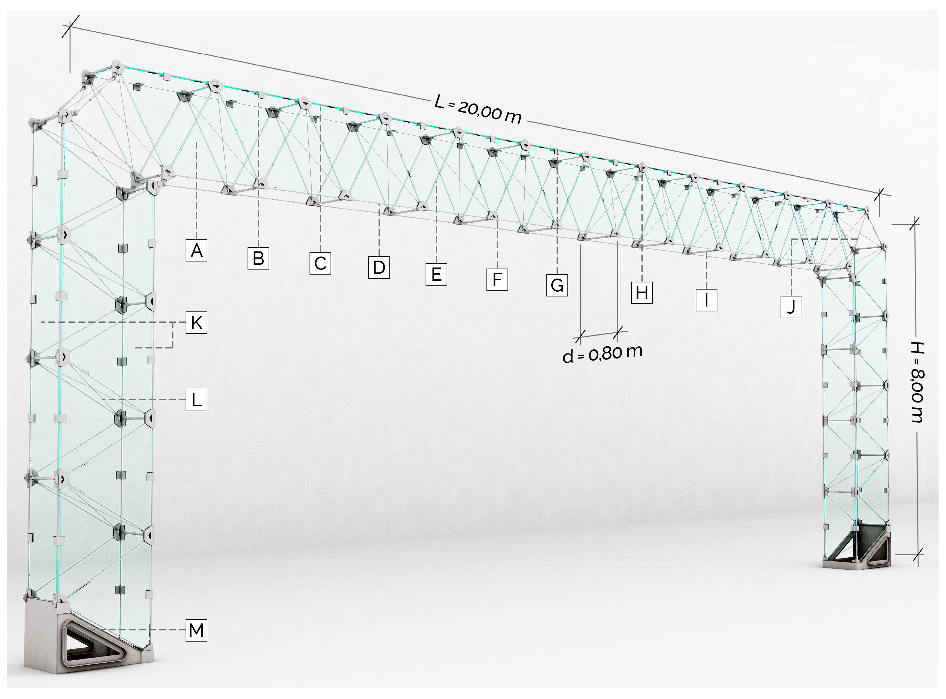
The TVTγ-bis frame is a 20 m single span and single story portal. Both the beam and the columns are designed with the TVTγ-bis technique (
Figure 4), hence the use of strands as pre-stressed reinforcement prevents the reduction of the mechanically resistant section caused by the mutual connection of the bars. Moreover, thanks to the highest yielding limit of the strands, a smaller cross section is necessary, increasing the transparency of the whole assembly and its mechanical behavior.
The beam of the TVTγ-bis portal has a segmented U-upside-down glass section: spaced by 800 mm, the twin webs are each made of 23 equilateral triangular panels with 1500 mm sides organised in a Warren scheme ([A] of
Figure 5. The horizontal outer flange is composed of a series of 12 quadrilateral panels ([B] of
Figure 5). The two webs are horizontally connected by means of steel tubes screwed at the 25 nodes ([I] of
Figure 5). The two outer extremities of the beam span of 18856 mm and its net height is 1401 mm. As confirmed by further analyses, an inner glass flange was determined to be unnecessary. Therefore, the U-upside-down section was adopted for the whole beam, benefiting from a reduced weight and technological simplicity.
The 7271 mm height columns have a square TVTγ-bis glass section. Similar to the beam, the two parallel webs are made of eight triangular equilateral panels. Ten steel nodes mutually connect their vertices through the strands. The flanges ([K] of
Figure 5) are both composed of four rectangular panels.
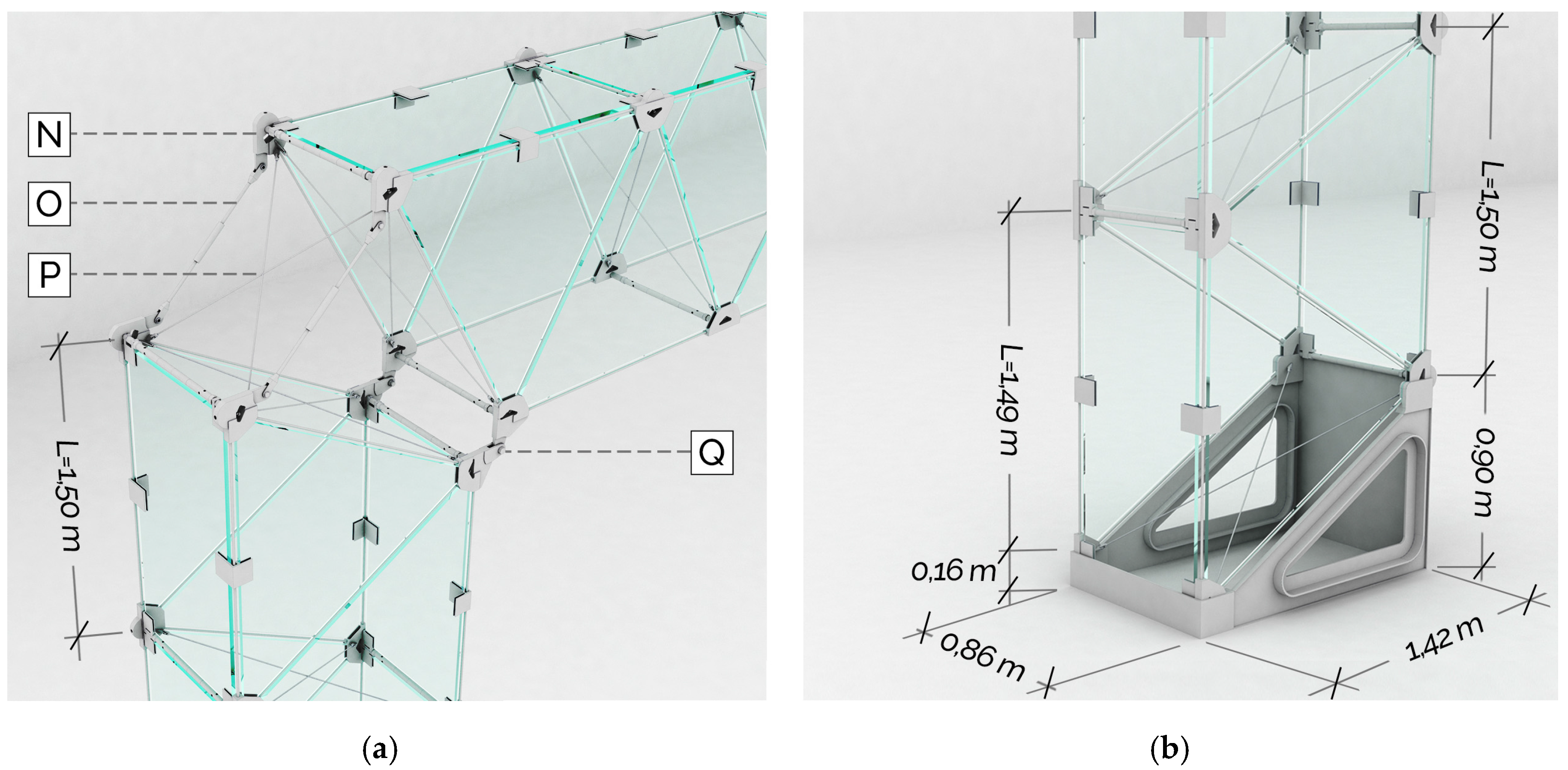
The beam-to-column joint is installed between the four end nodes of the beam and the four end nodes at the top of the column respectively (
Figure 6a). On the outer side, two chains made of a two steel bars are screwed at the nodes through a fork end and an M14 bolt. An intermediate steel sleeve permits the length regulation of such chain (detail [O] of
Figure 6a). A cross-bracing strand system increase the torsional stiffness of the joint. At the bottom (inner side), a finger joint connection with an M24 linchpin is located at a distance of 65 mm from the TVTγ-bis nodes (detail [Q] of
Figure 6a). Finally, this joint solution achieves a greater transparency level and by conveniently graduating the lengths of the bars at the outer side. Various amplitudes of the angle between the beam and the column are possible in the range of 60°–120°, yielding an enlarged set of possible architectural solutions for the pavilion.
The column-to-base joint (
Figure 6b) transfer the loads from the portal to the foundation while managing the geometrical transition from the horizontal base plane to the triangular segmented Warren sequence. Different heights for inner and outer steel plates re-establish the structural integrity of the flanges. Welded to those steel flanges, the webs are made of twin triangular steel plate with a central homothetic hole stiffened by a continuous transversal rib. Thus, while the ratio between voids and solid of the joint is increased, such triangular cross-section cells are highly resistant.
3.3. Diffuse Longitudinal Transparent Bracing System
The outer skin of the TVT Pavilion performs as a bracing system as well as protection from weather conditions (
Figure 7 and
Figure 8), and it is made of a series of hybrid pre-compressed glass panels connected to the frame portals. The strategy of supporting the horizontal longitudinal loads is based on the diffuse bracing provided by the panels according to the redundancy and robustness principles of FSD. All the panels are activated in the presence of wind or earthquake to mechanically transfer the shear forces at the frame portal and the base. Moreover, in case of the accidental failure of one of them, the neighbouring panels are able to adsorb extra loading with an alternative path.
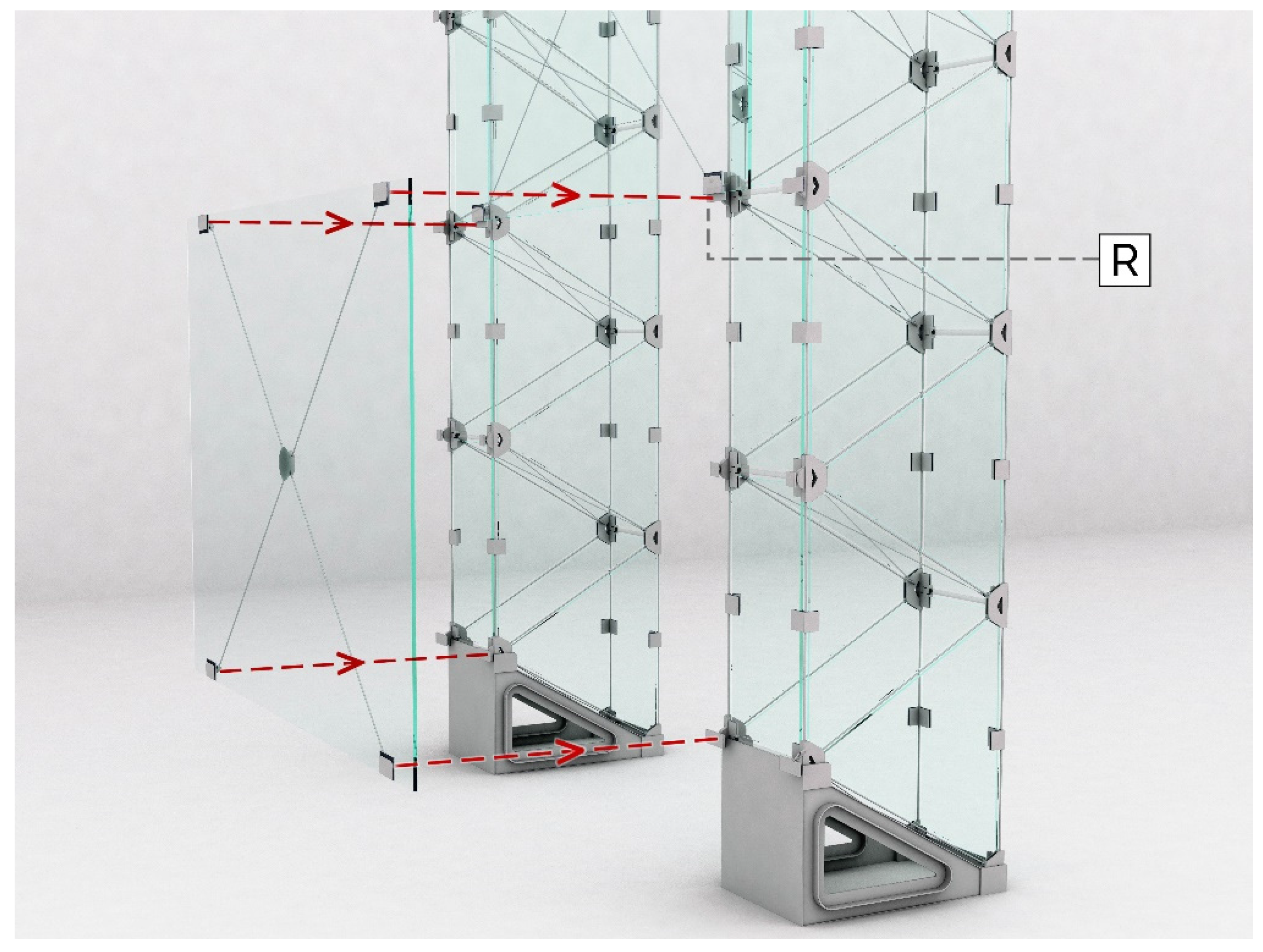
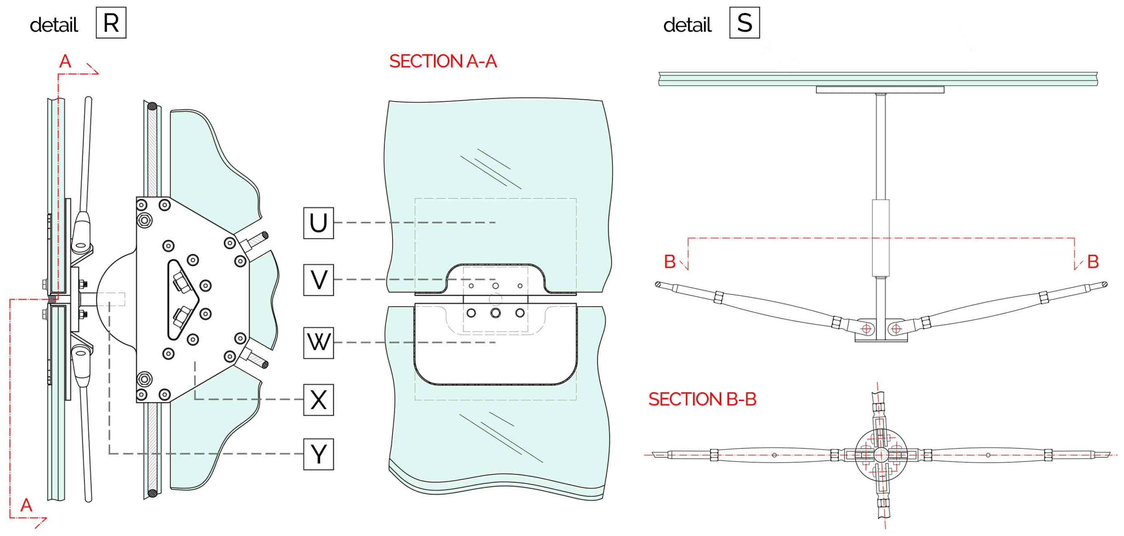
The rectangular glass panel is the hybrid glass-steel re-interpretation of the classic metallic cross bracing system: a three-layered HS rectangular glass panel is pre-stressed by means of two diagonal steel cables, whose extremities are at the panel vertices. Thus, the compressed zone is generated along the diagonals of the panel due to pre-stressing counterbalances for the traction forces induced by the external load. In case of glass breakage, the cables are still able to withstand a reduced amount of that horizontal force. The panel is a laminated 8 + 1.52 + 8 + 1.52 + 6 thick. The latter pane has no structural purpose: its only aim is to provide the system a higher redundancy and hierarchy, so that in case of accident, the double structural panel is protected by the 6 mm outer sacrificial panel.
The mutual load transfer between cables and glass occurs at the interface of rounded recesses practiced in the panel, which allows the interlocking of a steel plate right inside (detail [W] of
Figure 9). The extremities of the cables are connected at the inner side of the plate. The steel insert works by unilateral contact in the transferring of the compression forces to the panel, playing the same mechanical role as the steel nodes within the TVTs. The panel is pre-stressed and then mounted at the TVTγ-bis outer nodes, where specific supports, made of a steel plate with a pole screwed on each TVT node, are arranged (detail [Y] of
Figure 9).
Roof and wall panels differ in the position of the cross cables with respect to the glass, and consequently of the modality of its pre-compression. In the wall panels, the cables act in a plane parallel to the midplane of the glass (
Figure 7). The cables cross within a suitable steel point fixing, adhesively bonded to glass with the aim of favouring the distribution of compression stresses.
In the roof panels, due to the vertical loads (
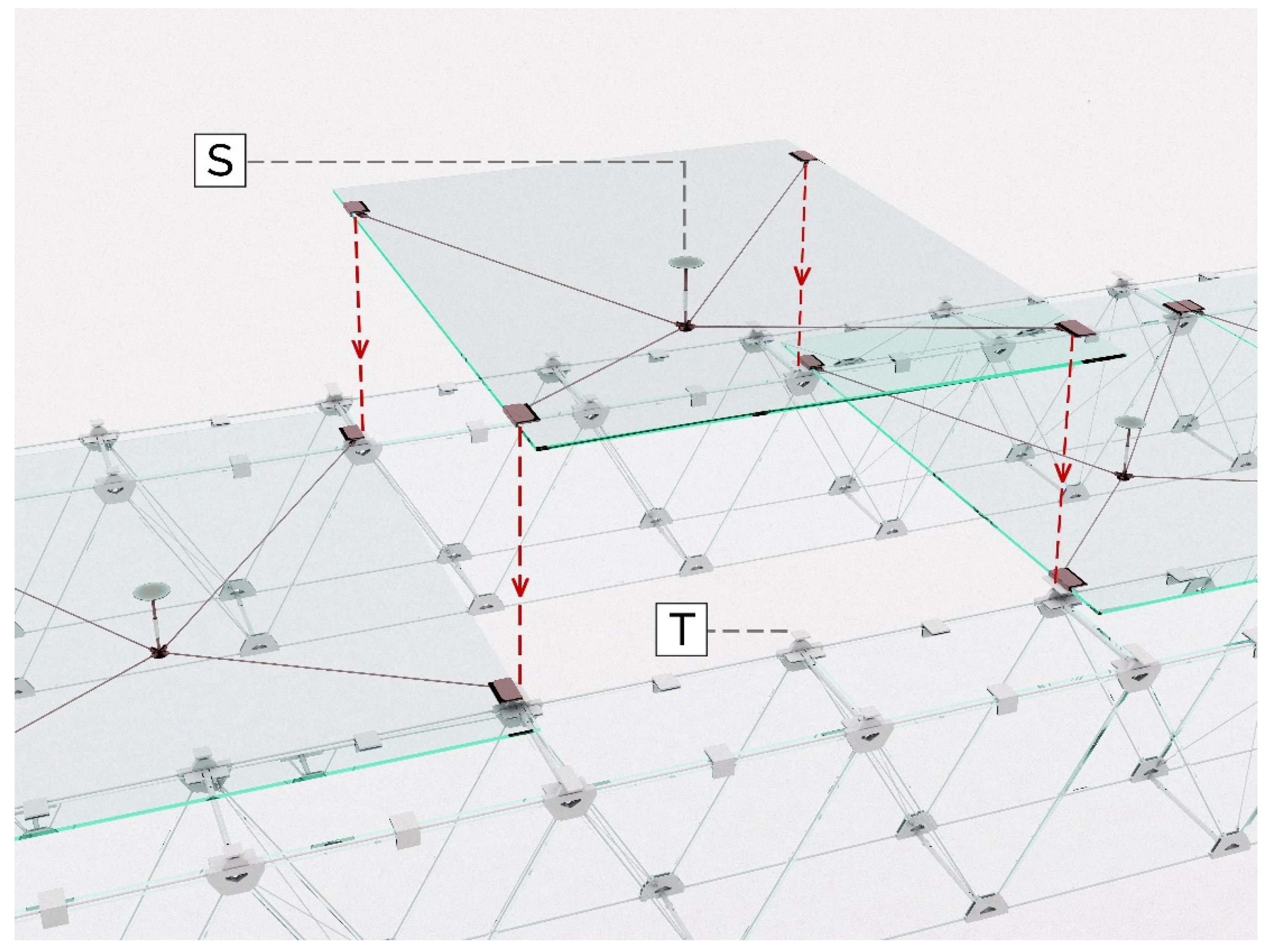
Figure 8), the panel is pre-compressed as a reinforced plate through the cables and a central tubular strut. Therefore, the deflection caused by the weight of the panel is balanced by the pre-stressing of the cables. To avoid excessive localized stresses, a circular 200 mm plate is welded at the top of the strut and adhesively fixed at the glass panel (detail [S] of
Figure 9). An additional out-of-plane-load support is located at the midspan of the shortest side of the panel (steel plate and pole, detail [T] of
Figure 8).
Except for the minimal opaque presence of the cables and the central fixings, the bracing panels are fully transparent. Moreover, all of them may be equipped with integrated devices with the aim of fulfilling the insulation, shading, waterproofing, energy production and ICT requirements, besides their structural purposes. In order to standardise and reduce production costs, two sizes for the wall panels and two for the roof panels are employed.
3.4. Façades
The façades constitute the front and back walls of the TVT Pavilion and are installed on the first and the last TVTγ-bis portals. Each of them has a surface of 160 m2 (20,595 × 8076 mm), which is made of 40 panels (four different types). The four point–supported panels are linked through a commercial spider system to elliptical cross sectioned aluminium mullions. A vertical slotted hole at the top of the mullion allows the transferring of the out-of-plane actions only, while the vertical load is sustained by the base-joint. The spacing of the mullions follows the position of the TVTγ-bis nodes. A 15 mm waterproofing sealant accommodates deformations and tolerances of the panels.
4. Methods
The TVT Pavilion mechanical behavior is numerically investigated by means of the software Straus7 release 2.3.3 [
33]. The aim was to assess the strength and the stability of both the global system and its components by means of FEA. Developing an accurate and consistent numerical model is always recommended, but it can lead to an excessive and time-consuming process. The strategy followed in the present research consists in realizing multi-scalar numerical manageable models from local to global. The higher order model is less accurate with respect to the lower one from a FEM viewpoint, but still suitable for its specific purpose. Development emerges from fully detailed local models, then a beam-segment model, a beam model, a frame model and finally a global model were developed, with each of them is mechanically akin to the lower one. Linear and non-linear analyses were conducted. The latter considering material, contact and geometric nonlinearities.
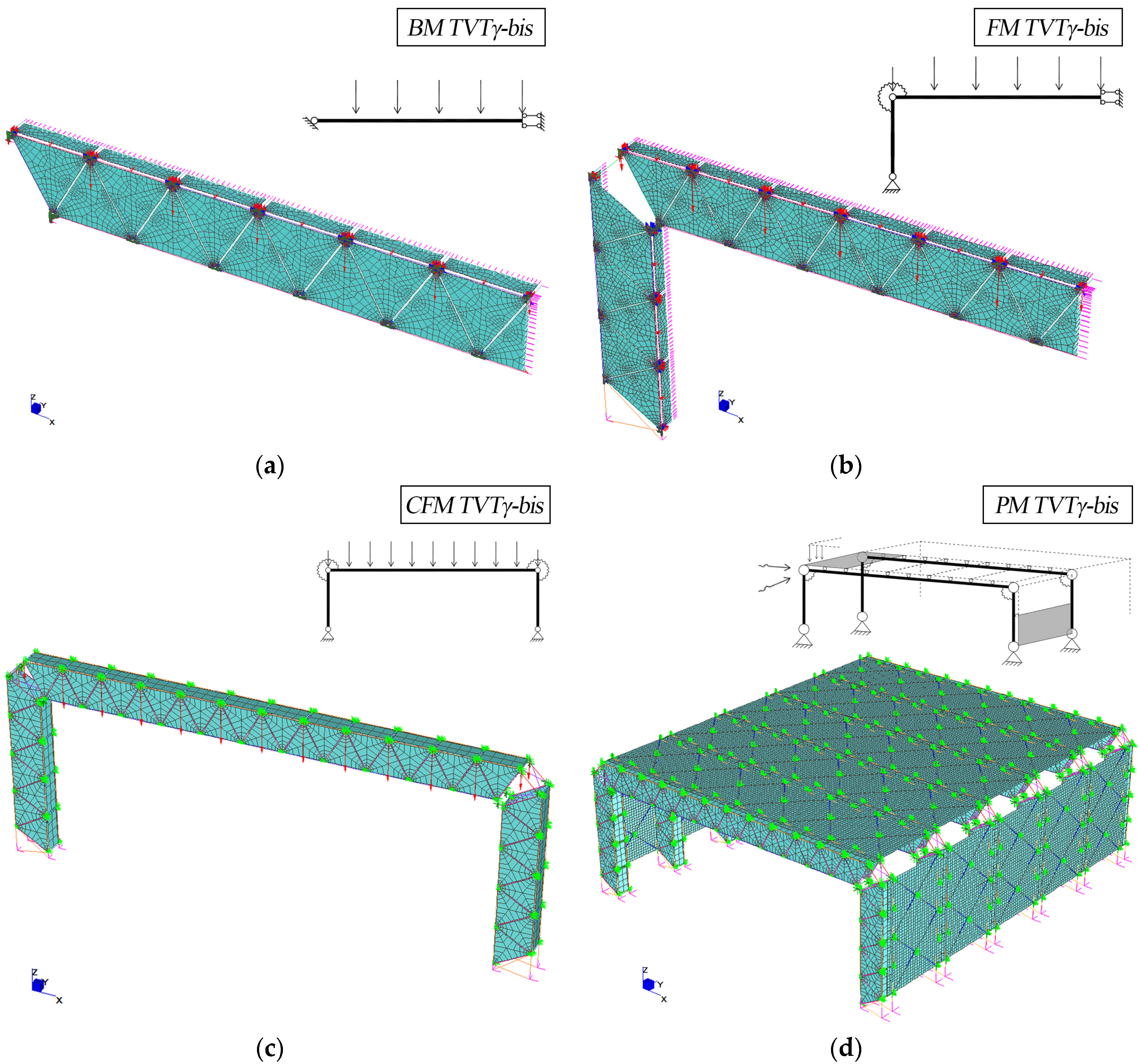
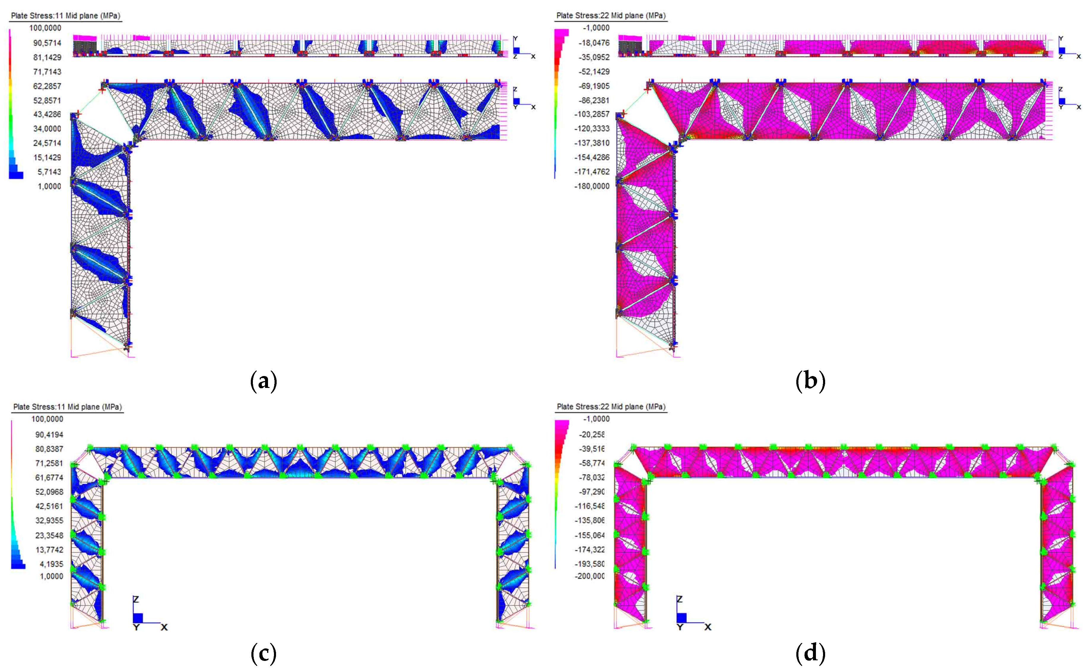
This paper presents the results and the discussion of the main numerical models developed for the TVT Pavilion (
Figure 10), whose purposes are the followings:
BM TVTγ-bis (Beam Model): 3D model of a quarter of beam (double half-symmetry for geometry and loads). The beam is pinned at the extreme nodes. The purpose is to assess the ULS strength and ductility and the buckling phenomena;
FM TVTγ-bis (Frame Model): 3D model of a quarter of beam and half column (double half-symmetry with respect to the mid plane of the portal and transversal mid plane of the beam). Its purpose is to study the mechanical behavior of the portal. Special attention is paid to the corner joint which is crucial for the overall portal study;
CFM TVTγ-bis (Complete Frame Model): Simplified 3D model of the portal frame, calibrated on the previous one to obtain the same static performances. It is used as frame in the PM TVTγ-bis;
PM TVTγ-bis (Pavilion Model): 3D global model of the pavilion, made of 6 CFM TVTγ-bis and hybrid glass panels as bracing.
Although the equivalent geometrical imperfections are usually introduced in the models because of the slenderness of glass components, they were only considered in the sizing of the structural parts carried out with analytical calculations. Indeed, in the previous studies, TVTs FEA output was scarcely affected by the introduction of imperfections, and therefore, in this research, imperfections are not considered in FEMs.
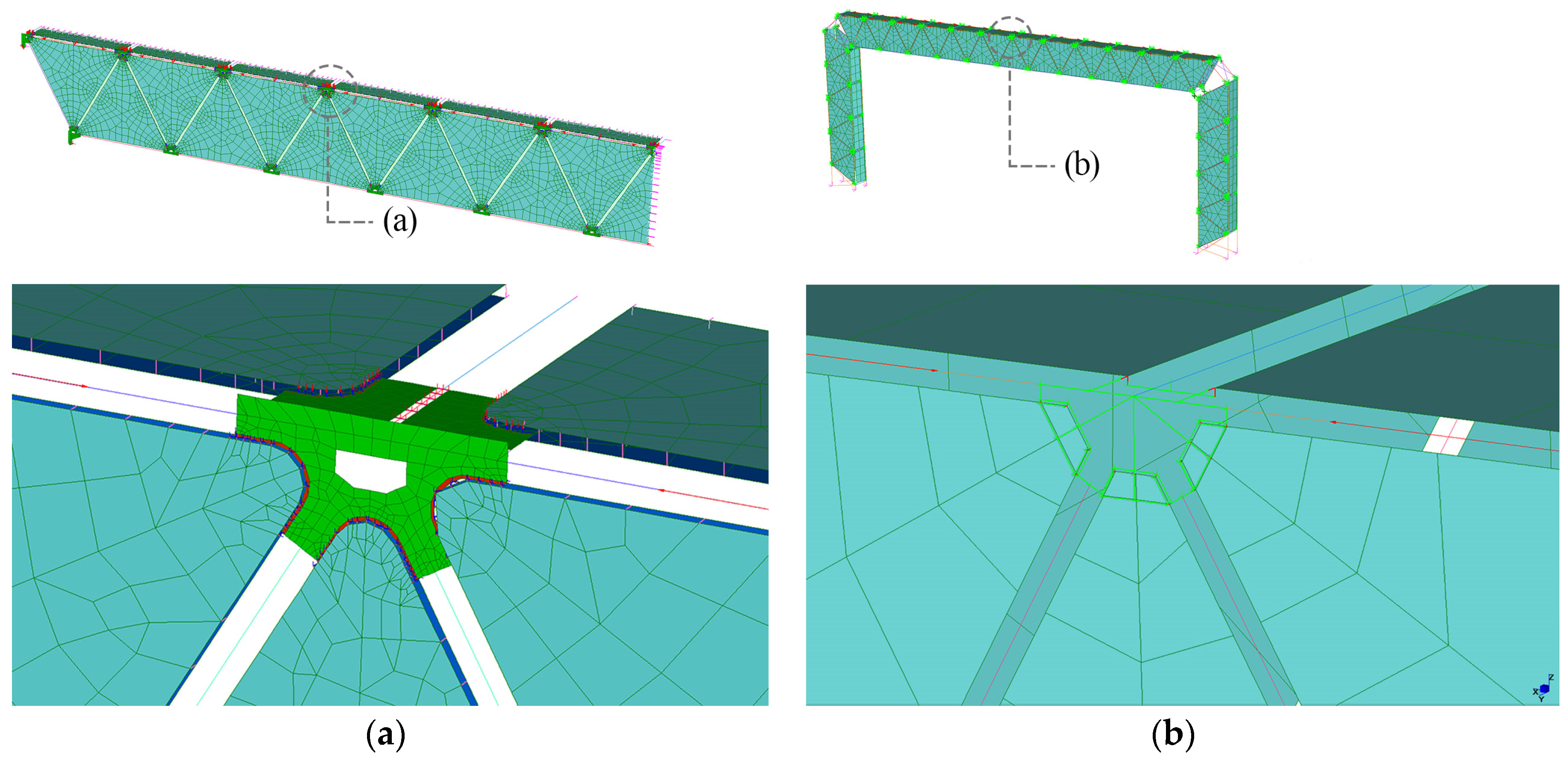
The outer layer of the laminated panel of the bracing system has no structural role, and as a consequence it is considered only as a dead load. Leading to a conservative approach, the PVB interlayer is modelled as an out-of-plane constraint for the twin glass panes, neglecting its shear stiffness. Therefore, the laminated panel is modelled as two parallel meshed plates with an out-of-plane pin connection (
Figure 11). The level of detail reached in the models is dependent on their size. The mesh refinement is scaled accordingly, as well as the accuracy in the contact of the components within the system.
Figure 11 shows the node neighbourhood for a detailed model (a) and for a simplified model (b). In the first case, the aluminium spacer is introduced as a strip of (red) plate elements surrounded by special links to simulate the contact with the glass and the out-of-plane restraint. In the second case, the simplified model is calibrated on the previous one.
5. Multiscalar Modelling and Analyses Result
5.1. BM TVTγ-bis Model
In the preliminary phase, the components of the TVT system were designed at first with analytical calculations descending from the Warren truss scheme [
34]. The aim was to localize the main tensioned and compressed areas and provide them with suitable structural load bearing capacity. The 10 + 1.52 + 10 mm thickness of glass was proved by a non-linear buckling analysis on a beam-segment model made of two triangular webs and one rectangular flange.
Then, a three-dimensional FE model was built by using beams, cables, plates, and links to simulate steel beams, strands, glass panels, and their mutual connections, respectively. The modeling phase was strongly assisted by the TVTs state of the art—or rather past experimental and numerical—outcomes. The external beam joints were pinned, while appropriate boundary conditions assured the symmetry along the transversal and the longitudinal midplanes. By setting up the material properties, the dead load is automatically affixed. For non-linear analyses, the live loads are concentrated in the steel nodes, accordingly with the load path design, and introduced step by step (
Figure 10a).
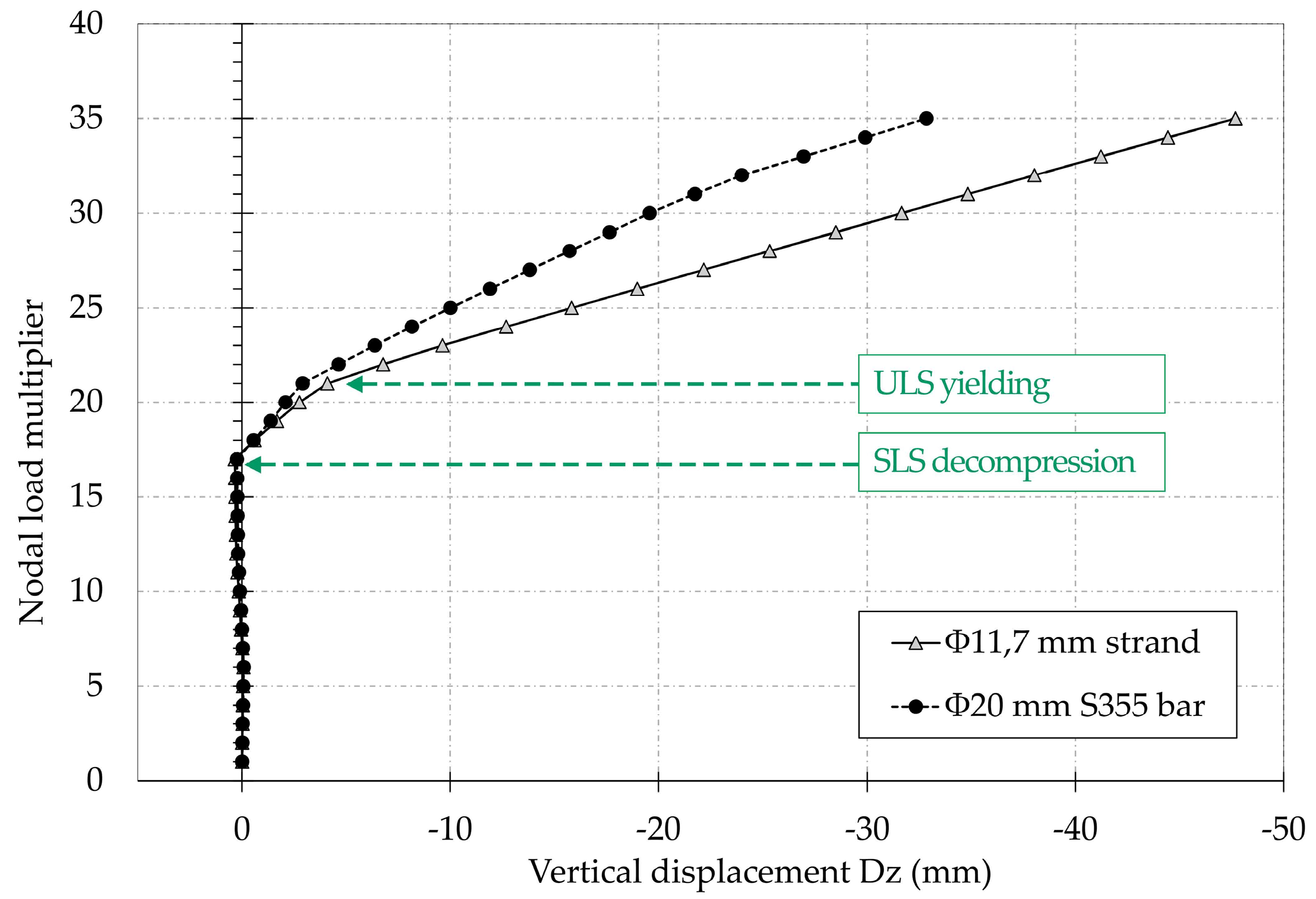
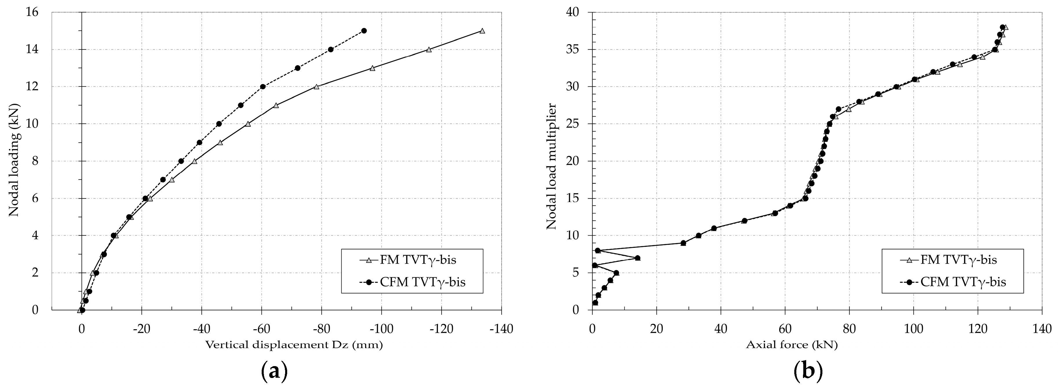
With the aim of selecting the optimal solution between the TVTγ-bis with pre-stressed bars and the TVTγ-bis with pre-stressed strand, a non-linear comparative analysis was performed. Until the decompression of the SLS of glass panels, the two investigated structures manifested similar stiffness (
Figure 12). Beyond that limit, for the same load, the beam with bars is stiffer than the beam with strands, but in the meantime, its behavior is less ductile. Then, the TVTγ-bis with pre-stressed strand was adopted due to its ductility. However, the deflection of both solutions accomplished the SLS requirements.
The FEA of the BM TVTγ-bis confirmed the static behavior expected from the analytical calculations, instead of the deformative behavior that could not have been predicted because it is mostly influenced by the presence of the vertical triangular glass panels.
Figure 13 reports the maximum and the minimum stresses for non-linear static analysis, beyond the SLS of panels decompression. Higher values of tensile stress in glass are located along the edges of the panels close to the external supports. Regardless, they reach a value greater than 9 MPa.
5.2. FM TVTγ-bis Model and CFM TVTγ-bis Model
The FM TVTγ-bis model (
Figure 10b) highlights the real expected static and deformative behavior of the beam under the influence of the column and the beam-to-column node stiffness. The finger joint connection was modelled by using plates, while the nodes and the bars by links and beams.
The lower strand of the beam reaches the ULS of yielding at the mid-span length for a nodal loading of 12 kN, showing as expected higher deformations in comparison with the BM TVTγ-bis. However, the adopted load configuration of uniform nodal loads is not matching the real design requirements because the mid-length support of the bracing panel (detail [T] of previous
Figure 8) carries a three times lower load with respect to the adjacent supports (or rather where the bracing panel is fastened on the steel plate). Consequently, the structural performances are even greater than those simulated by the present model.
Besides the maximum axial force at the mid-span length, the greater displacement of the panels’ lower edge from their slot appears. The deflection of the beam is limited due to an additional pre-stressing practiced on the outer strands of the columns.
The fine FE modelling detail level of the FM TVTγ-bis constituted a limit for its implementation on a global model PM TVTγ-bis. To lighten the computational task, a simplified model CFM TVTγ-bis (
Figure 10c) was created. In the latter, preserving the same static outcomes of the FM TVTγ-bis, a coarse mesh was adopted, fewer links or point contacts between steel and glass were used, and the flanges of the portals were substituted by suitable equivalent beams whose stiffness was deducted from a detailed local model. The comparison between the models at the ULS shows a good agreement (
Figure 14). At the increasing of the live loads, the CFM TVTγ-bis results are stiffer than the FM TVTγ-bis. However, both the SLS of glass decompression and the yielding of the strands occur for the same nodal loads, but with a 10% displacement difference (
Figure 14a). The glass stresses comply in both the models if evaluated at an appropriate distance from their vertices in order to avoid peak values (
Figure 15). Since the axial forces of the outer strands are conditioned by the introduction of the equivalent beam flanges, a consistent comparison is not possible, whereas the lower strands of both models are perfectly agreed, as shown in
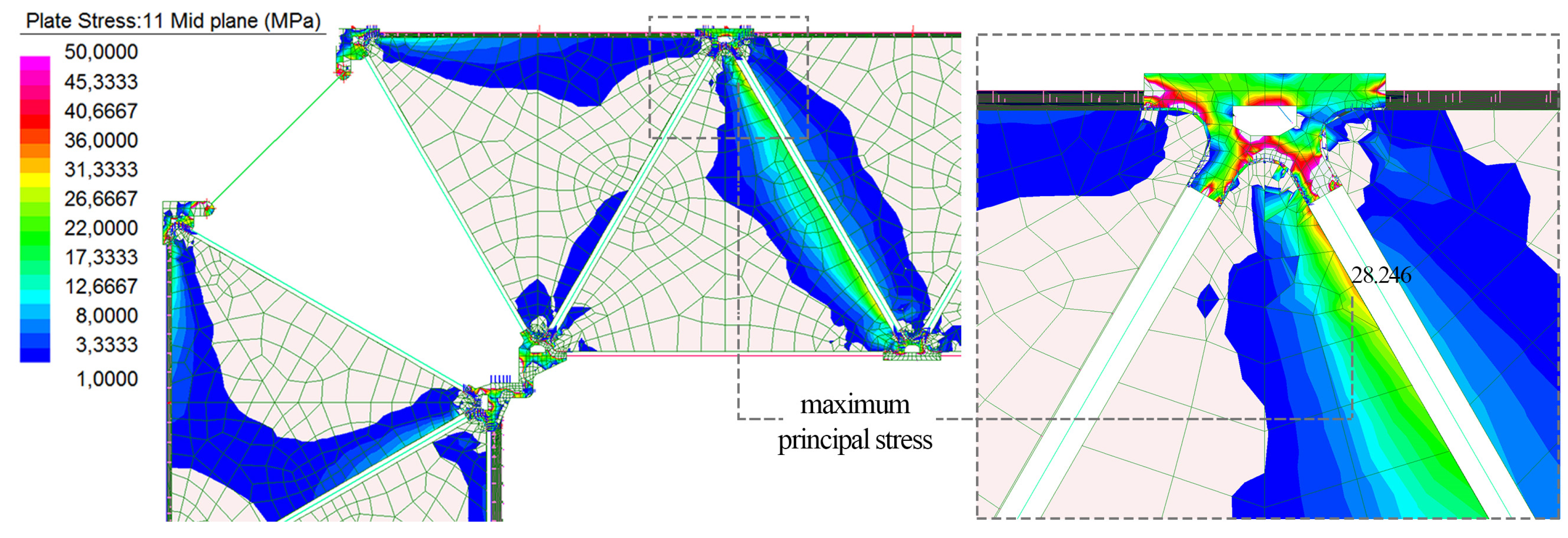
Figure 14b. This result enables the CFM TVTγ-bis to be used as a frame portal in the global PM TVTγ-bis due to its static equivalence with the FM TVTγ-bis. The maximum principal peak value is reported in
Figure 16, evaluated on the more detailed FM TVTγ-bis. However, such value is below the value from Equation (1).
5.3. PM TVTγ-bis Model
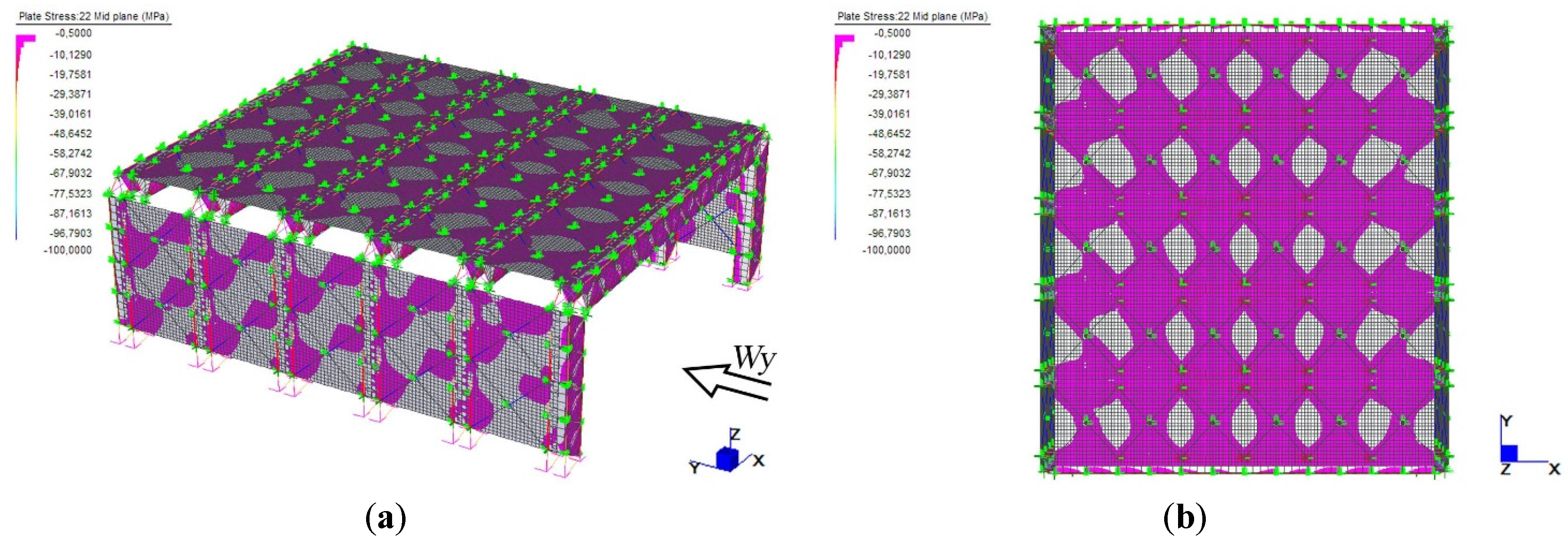
The aim of the global model PM TVTγ-bis (previous
Figure 10d) is to verify the overall load bearing capacity and the compliance with the hierarchy principle of the FSD. Herein, six models of CFM TVTγ-bis spaced by 4300 mm are braced by hybrid panels modelled with shell and beam elements. Suitable link elements allow the loading transmission, simulating the structural behavior of the plate-and-pole connections. The façades are excluded from the model, considering only the wind loading transferred to the nodes of the first and the last TVTγ-bis portals. Such a simplification is compatible with the conception and the designed structural behavior of the TVT Pavilion. Moreover, the analysis and the safety assessment of the façade was carried out separately based on the guidelines CNR DT 210 [
23].
The stresses on the pavilion components are the results of combinations of dead, wind (transversal and longitudinal), snow, roof and earthquake loads as from [
35]. In the non-linear analyses, the sequence of loading follows the assembly phases, in order to take into account the pre-stressing of the strands. The construction site was located in Trieste to maximize the entity of the wind action, while the earthquake load combinations were lower than the wind ones because of the lightweight nature of the pavilion.
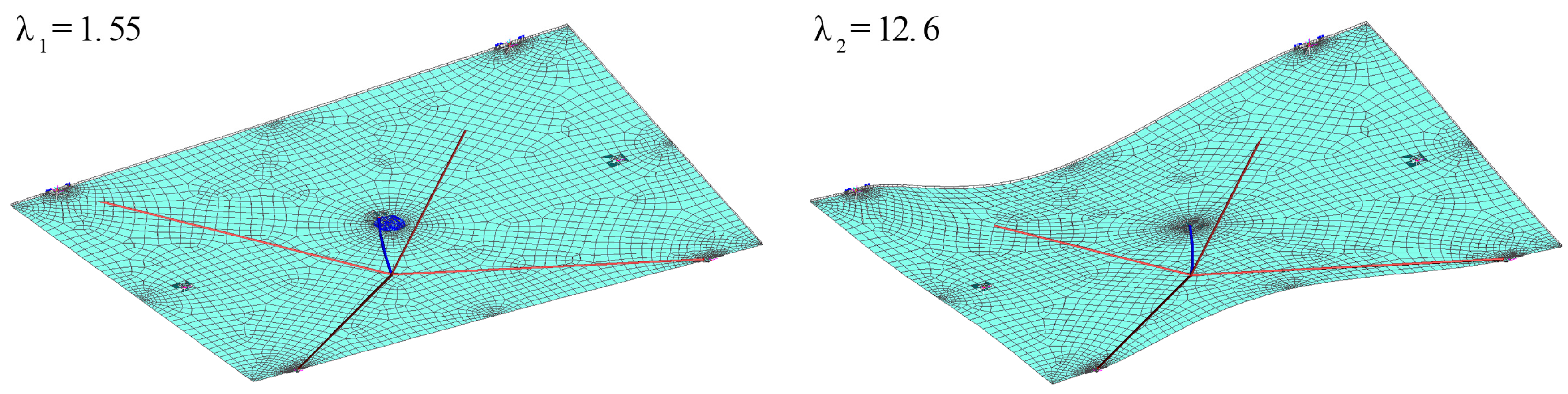
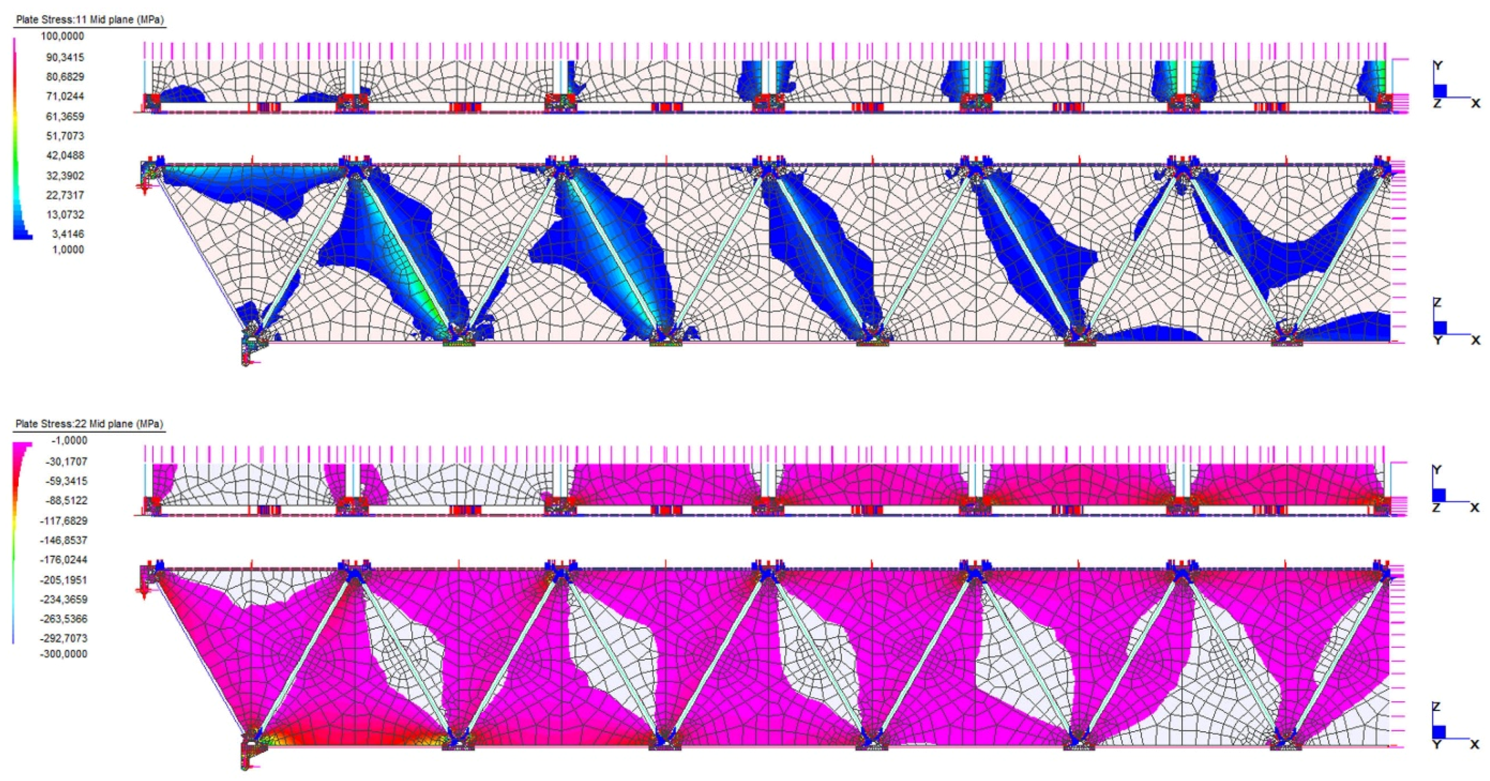
In the combinations with prevailing horizontal load, the bracing panels manifest the typical tie-strut mechanism in the midplane of both the wall and the roof panels (
Figure 17). However, the glass panel is mostly affected by the presence of one main diagonal “strut” zone since the pre-stressing of glass has a favourable effect. Indeed, the opposite diagonal zone is decompressed as a compensation to the external induced tractions.
The maximum positive stresses in glass are located in the portal frames within the limits of technical recommendations [
32] as shown by previous
Figure 16. Neither local nor global failure mechanism was observed for different load configurations. The ULS of yielding of the lower strands, as much stressed structural elements, was not overstepped. In linearly growing the live loads, the yielding of the lower strands always precedes the buckling of the bracing panels for any load combination, in accordance with the structural hierarchy and ductility. Moreover, the buckling of the bracing panel is calibrated with respect to the mechanism showed in
Figure 18. The first buckling factor for in-plane loading of a roof bracing panel concerns the instability of the steel strut. The panel can buckle for a much higher load. A further safety margin can be achieved by increasing the stiffness of the strut. At the SLS, the PM TVTγ-bis is not suitable for the evaluation of deflections because it was created with ULS static equivalence.
6. Discussion and Conclusions
Hybridism is a unique strategy for reaching long spans with glass components in accordance with the FSD. The TVT constructional system, based on segmentation and the mutual pre-stressing of the components, is able to maximise the mechanics of both materials with high performances both at the ULS and at SLS, guaranteeing the full transparency of the load bearing structures.
The technical and technological feasibility of a long-spanned hybrid pavilion is demonstrated in the models used here, which are calibrated on the past numerical and experimental experiences of the 12-m-spanned TVTγ beam. The TVT Pavilion is able to overcome state-of-the-art glass structures competitors thanks to its 20 m-spanned TVTγ-bis frame portal and a diffuse hybrid pre-stressed glazed bracing system. Additionally, thanks to the high standardisation of its components, the costs of fabrication and reparse are certainly reduced.
Possible uses of the TVT pavilion are as exhibition buildings, sheltering of artefacts, or advanced building envelopes. Indeed, the sacrificial layer in the bracing panels constitutes both a structural safety measure and the possibility to integrate in the interlayer thickness miniaturized devices for energy production, lighting or communicative purposes. By admitting various roof slopes, the beam-to-column joint permits wide architectural design freedom, and concurrently the use of fewer and simpler elements improves the transparency of such a connection.
The limitations of the Energy Gallery have been overcome. With the use of pre-stressed strands, the TVTγ-bis system reaches longer spans, achieving more transparency. Moreover, the higher ductility level increases the possibility of using it in presence of static and dynamic loads. By means of a calibrated design, the yielding of the most tensioned (lower) strand always precede the buckling failure of glass. The high local and global redundancy—obtained through hybridism, ductility, segmentation, and mutual pre-stressing—makes this system suitable for the intended use.
The post-breakage behavior of the TVTγ-bis is objective of further work. After the breakage of multiple components, the system is expected to maintain a sufficient load bearing capacity. Moreover, the substitution of the damaged parts gives the opportunity for a cost-saving replacement strategy. The post-breakage behavior and the replacement of components were observed for the TVTγ prototype. After the yielding of the lower bar, the prototype was unloaded and the damaged steel member was changed. In a further test, the buckling of one glass panel was observed. At the unloading, the yielded steel and the crushed panel were substituted. An undamaged new prototype was obtained. The accidental rupture of multiple panels was also experienced on the TVTγ prototype, and the damage specimen could withstand its own weight and part of the live loads. The probabilistic (accidental) failing of multiple panels and their effect on the global structural behavior can be simulated in future FEA works.
Some design recommendations are provided. The steel relaxation and the thermal effects can affect the pre-stress of strands, reducing it. This aspect has not been considered and should be tested with an experimental prototype.
The longitudinal diffuse bracing system appears to be one of the most innovative features of the TVT Pavilion because glass is efficiently used in the load transmission and not weakened by exposing it to positive stresses. The pre-stressed cables halved the apparent traction resistance of the panel and constitute an additional safety measure in case of the accidental failure of the glass. The overall conception is consistent with the glass design philosophy. The connections of the hybrid panel and the links of the panel with the structure underneath are the key design points of the system. Future study is intended to experimentally and numerically evaluate the buckling of such a promising bracing system by varying its main design parameters. Experimental validation on the connections is also needed.
The adopted multilevel methodology accomplishes time saving ULS structural checks. Hierarchy and structural redundancy are also verified. However, SLS decompression and deflections controls were not possible in the global PM TVTγ-bis due to the simplification induced by the CFM TVTγ-bis. Further work is needed to calibrate a high-resolution models or alternative models to fill this gap. In conclusion, the obtained results confirm the development of the designed controllable load paths and a good distribution of the compression stress in the glass components.


