The Experience of International Sustainability Protocols for Retrofitting Historical Buildings in Italy
by
 ,
,
Veronica Lucia Castaldo
1, 
Anna Laura Pisello
2,* ,
,
Paola Boarin
3,
Alessandro Petrozzi
1 and
Franco Cotana
2 1
CIRIAF—Interuniversity Research Center on Pollution and Environment “Mauro Felli”, Via Duranti 63, 06125 Perugia, Italy
2
Department of Engineering, University of Perugia, Via Duranti67, 06125 Perugia, Italy
3
School of Architecture and Planning, Faculty of Creative Arts and Industries (CAI), The University of Auckland, 26, Symonds Street, 1010 Auckland, New Zealand
*
Author to whom correspondence should be addressed.
Buildings 2017, 7(2), 52; https://doi.org/10.3390/buildings7020052
Submission received: 26 April 2017
/
Revised: 9 June 2017
/
Accepted: 12 June 2017
/
Published: 16 June 2017
(This article belongs to the Special Issue Passive Strategies for Building Renovation in Temperate Climate)
Abstract
:The sustainability and efficiency of buildings represents a crucial issue since the building sector is currently responsible for more than 40% of energy consumption and emissions. This concern is extended to historical buildings, as they are typically low-performance constructions usually equipped with ineffective systems. For these reasons, the upgrade of historical constructions from an energy and environmental perspective is urgent, especially in those countries where such buildings represent more than half of the building stock. This work concerns the refurbishment of a historical Italian building by integrating passive and active solutions to optimize the indoor thermal comfort and the energy performance. To this aim, the innovative GBC Historic Building® rating system, a new tool evaluating the sustainability level of conservation-related activities on pre-industrial buildings, is applied. A combined trigeneration heat and power plant with an absorption chiller to produce cooling and powered by vegetable oil is installed in the building. A dynamic simulation of the building is also carried out to predict the post-retrofit energy performance upgrading. The final aim is to propose an integrated approach for the preservation and energy upgrading of existing constructions by improving their energy performance and environmental quality while protecting their heritage value.
1. Introduction
Historical and heritage constructions constitute a non-negligible percentage of the Italian building stock, i.e., more than 30% [1], where an improvement of building’s performance must consider the need for the preservation of their cultural and artistic value [2,3], on one hand, and the urgency of a widespread deep renovation, on the other. Unfortunately, such heritage buildings are often low-performance constructions due to the fact that they are equipped with ineffective and high-emissions heating, ventilation and air conditioning energy plants and are characterized by ancient and ineffective envelope technologies. Moreover, the energy, structural and architectural retrofit of this building stock is often very challenging due to the constraints of the existing regulations for the preservation of their historic value [4]. Therefore, it is very difficult to implement comprehensive passive and active strategies for the energy efficiency and environmental sustainability, since the architectural appearance of such buildings usually cannot be modified [5].
In this panorama, many strategies have been developed over the last decade to perform the both structural preservation and energy upgrade of heritage constructions without affecting their architectural quality [6]. For instance, a new tile for historical buildings’ roofs was developed in the Italian context [7,8]. The new tile presents the same aesthetical appearance of the historical ones but it is characterized by a higher solar reflectance capability and it is consequently able to optimize the building indoor thermal comfort by maintaining a lower roof surface temperature and avoiding the overheating of the indoor environment, especially in peak summer conditions. In the same scenario, an innovative tailored approach for the architectural and energy refurbishment of historic buildings was proposed in [9]. Such method is based on the combination of (i) the continuous monitoring of the building indoor microclimate conditions and (ii) the dynamic simulation of the building thermal-energy performance to assess the quality of the indoor thermal environment and evaluate the effect of different passive/active energy efficiency solutions. Furthermore, different retrofit scenarios based on an integrated innovative restoration approach for heritage constructions were compared in [10]. In this case, the benefits of the application of two combined strategies specifically prototyped for application in historic buildings, i.e., clay cool tiles similar to traditional historic tiles and a geothermal heat pump system with water storage tanks preventing the use of external units which could affect the integrity of the building façade, were investigated in a case study in central Italy. Moreover, an innovative small-sized anaerobic digester was developed for tailored integration in historic constructions for the improvement of both the energy performance and environmental sustainability [11].
The improvement of the thermal-energy behavior of heritage constructions by means of the implementation of tailored retrofit strategies represents also one of the main priorities of both national governments and the European Community [12]. However, while several energy and environmental certification protocols are already available for new and existing buildings with no heritage value, comprehensive tools and guidelines for the intervention on historic buildings are still very few. For example, a local version of the international LEED® (Leadership in Energy and Environmental Design) rating systems for New Construction and Major Renovation, i.e., LEED® 2009 Italia Nuove Costruzioni e Ristrutturazioni [13], has been developed by the Green Building Council of Italy to be applied for the deep renovation of existing buildings. However, although potentially applicable to historic buildings, such protocol is not suitable for the implementation of retrofit strategies on the heritage stock as it is not aligned with preservation principles and strategies. To tackle this issue and moving from the existing local rating system for major renovations, the Green Building Council of Italy has worked for the promotion of a dialogue between the sustainability criteria and the knowledge of the conservation world, developing a new tool called GBC Historic Building® for the voluntary certification of the sustainability level of conservation, rehabilitation and adaptation of historic buildings [14]. The protocol comprises all the different categories already included in LEED®, i.e., Sustainable Sites (SS), Water Efficiency (WE), Energy and Atmosphere (EA), Materials and Resources (MR), Indoor Environmental Quality (EQ), Innovation (ID) and Regional Priority (RP), with the addition of a brand-new category called Historic Value (HV). This last and new category aims at identifying and preserving the original historical and cultural nature of the construction by encouraging to apply retrofit solutions that are (i) non-invasive, (ii) reversible, (iii) consistent and compatible and (iv) durable over time. Moreover, any intervention on the historical building must be applied by trying to retain the original structure and materials and by promoting the environmental sustainability and energy efficiency of the heritage building without neglecting its original nature and configuration.
2. Motivation of the Work
Building upon the outlined premises, this work concerns the proposal of an innovative and tailored approach for the energy retrofit of heritage buildings based on the combination of (i) the application of the principles of the newly developed GBC Historic Building® rating system and (ii) the implementation of an innovative renewable energy plant for enhancing the environmental sustainability of such constructions. For this purpose, a pilot case study consisting of an ancient fortress in central Italy is selected and combined passive and active solutions are applied in order to enhance the overall thermal-energy performance of the heritage building.
The ultimate goal of the study is to demonstrate the feasibility of the integration of energy and environmental retrofit measures with the necessary structural and architectural upgrading of the historical building by improving its final performance without undermining the cultural and artistic value.
3. Methodology
The methodology applied consists of the following main steps:
- (1)
- analysis of GBC Historic Building® as a tool for energy retrofit;
- (2)
- selection of the historic building as case study;
- (3)
- architectural adaptation and energy upgrading of the building following the new GBC Historic Building® protocol;
- (4)
- pre-assessment of the improved energy performance achieved by means of dynamic simulation.
3.1. GBC Historic Building® and the Challenge of Energy Retrofit in Heritage Constructions
GBC Historic Building® (GBC HB, Italy) is a protocol specifically developed to be applied to “historic buildings”, i.e., constructions representing a “material witness having the force of civilization” [15], intended as pre-industrial constructions, conventionally built before 1945. The rating system can be used for projects seeking a range of intervention degrees, from conservation to renovation. In all cases, the main goal of the process must be the historic building’s major renovation, defined as action that involves significant elements of HVAC systems and the renewal or functional reorganization of interior spaces, considering a building envelope’s performance improvement consistent with the preservation of the heritage, architectural and construction features [16].
The innovative protocol has a broad applicability potential since historic buildings represent at least the 30% of the Italian and European building stock and are very different from both new and more recent existing structures in terms of building materials, construction techniques and HVAC technologies (when present). Initiated in 2012 by the Green Building Council of Italy through an interdisciplinary Technical Advisory Group, the development of the new tool started from the concepts of the existing LEED® (Italy) Italia rating system for New Construction and Major Renovation, by adapting the most critical aspects to the peculiar case of historical buildings, which are typically subjected to many constrains for preservation purposes. Additionally, the development phase included the integration of some new credits and new approaches introduced by the new version of the LEED® protocols for major renovations released at the time by the U.S. Green Building Council (LEED® v4 [17]) and other activities related to the credit weighting and testing on case studies.
The protocol has a maximum of 100 points to be assigned for the fulfilment of the credits across thematic areas Historic Value, Sustainable Sites, Water Efficiency, Energy and Atmosphere, Materials and Resources, and Indoor Environmental Quality, to which a further 10 points can be allocated to the topics Innovation and Regional Priority. Such modules are each composed by several forms, subdivided in prerequisites and credits. While the prerequisites are mandatory, the credits are optional. As outcomes of the development process and due to the integration of a brand-new topic, i.e., HV, the weightings and allocation of points across the areas have been modified (Table 1) in order to meet the requirements related to the fulfilment of conservation principles within the building process, with particular attention to the acknowledgement of heritage values as sustainability criteria [18].
Depending on the number of fulfilled credits, a final score will be assigned to the historic building which is being certified, determining the building’s final certification category. In particular, a score between 40 and 49 corresponds to a “Certified” level, between 50 and 59 to a “Silver” level, between 60 and 79 to a “Gold” level and over 80 points correspond to a “Platinum” level of certification.
Energy may be considered as a concern directly or indirectly addressed in many areas of GBC Historic Building®, precisely [19]:
- in the topic Historic Value, where the understanding of the historic building’s energy behaviour is essential to identify possible modifications or operational solutions for upgrading its performance. This goal is pursued mainly through the energy audit procedure;
- in the topic Sustainable Sites, where the impact on the ‘energy issue’ is more related to the overall quality of the urban environment and the improvement of connections and livability. This goal is pursued mainly through the (i) enhancement of public and alternative transportation, (ii) the quality of open-spaces, (iii) the reduction of urban heat island and an efficient illumination system;
- in the topic Energy and Atmosphere, where the highest number of points across the protocol are allocated. The category is based on the principle of building performance improvement compared to a reference condition, rather than a compliance with pre-defined performance levels. This goal is pursued mainly through (i) the energy commissioning of systems, (ii) the improvement and optimization of building energy performance, (iii) the integration of renewable energy sources, (iv) the refrigerant management and (v) the measurements and verification of the consumption in operation;
- in the topic Indoor Environmental Quality, where two alternative paths are offered in order to improve the indoor environment and protect the cultural heritage at the same time. This goal is pursued mainly through the (i) control and improvement of indoor air quality, (ii) the controllability of lighting and thermal comfort systems and (iii) the design and verification of thermal comfort.
3.2. Description of the Case Study
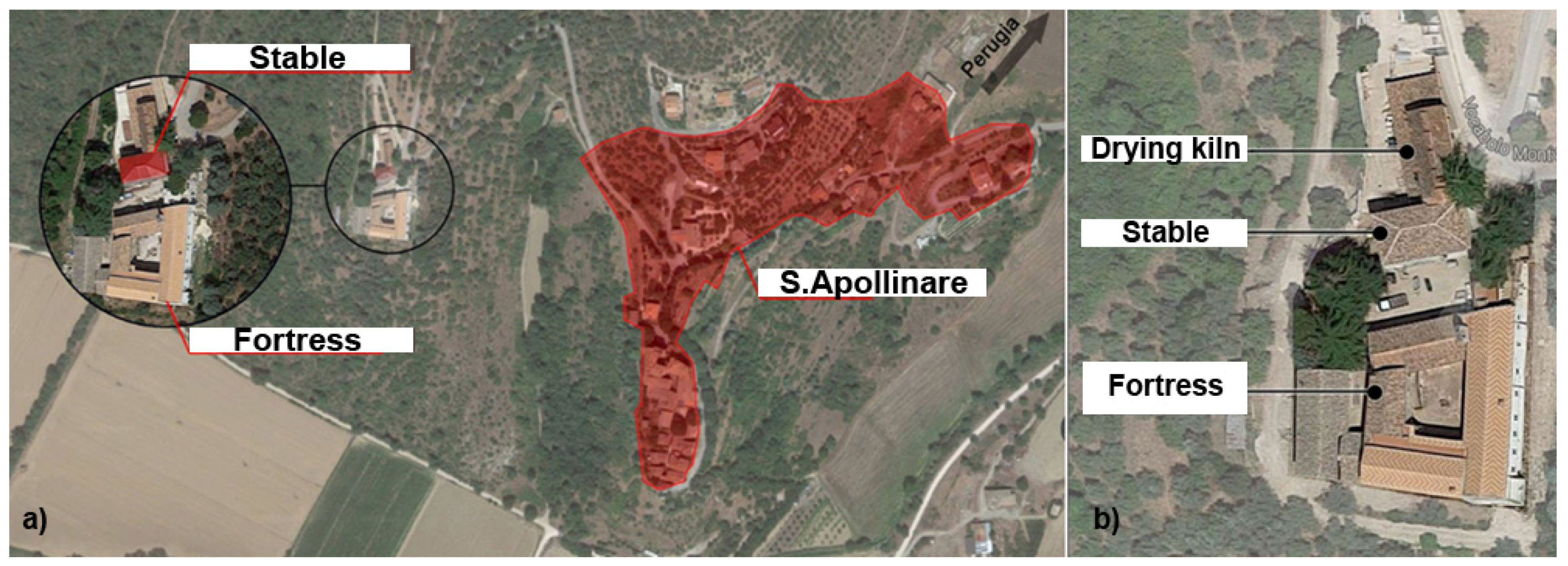
The case study building selected for the analysis is an old stable positioned inside the Sant’Apollinare Medieval Fortress, a Benedictine fortress situated 20 km south-east from the city of Perugia (Italy) and about 20 km far from the Trasimeno lake (Figure 1a). It is composed of three different and detached buildings, i.e., (i) the main fortress, (ii) the stable, which represents the pilot case study building, and (iii) the old drying kiln (Figure 1b).
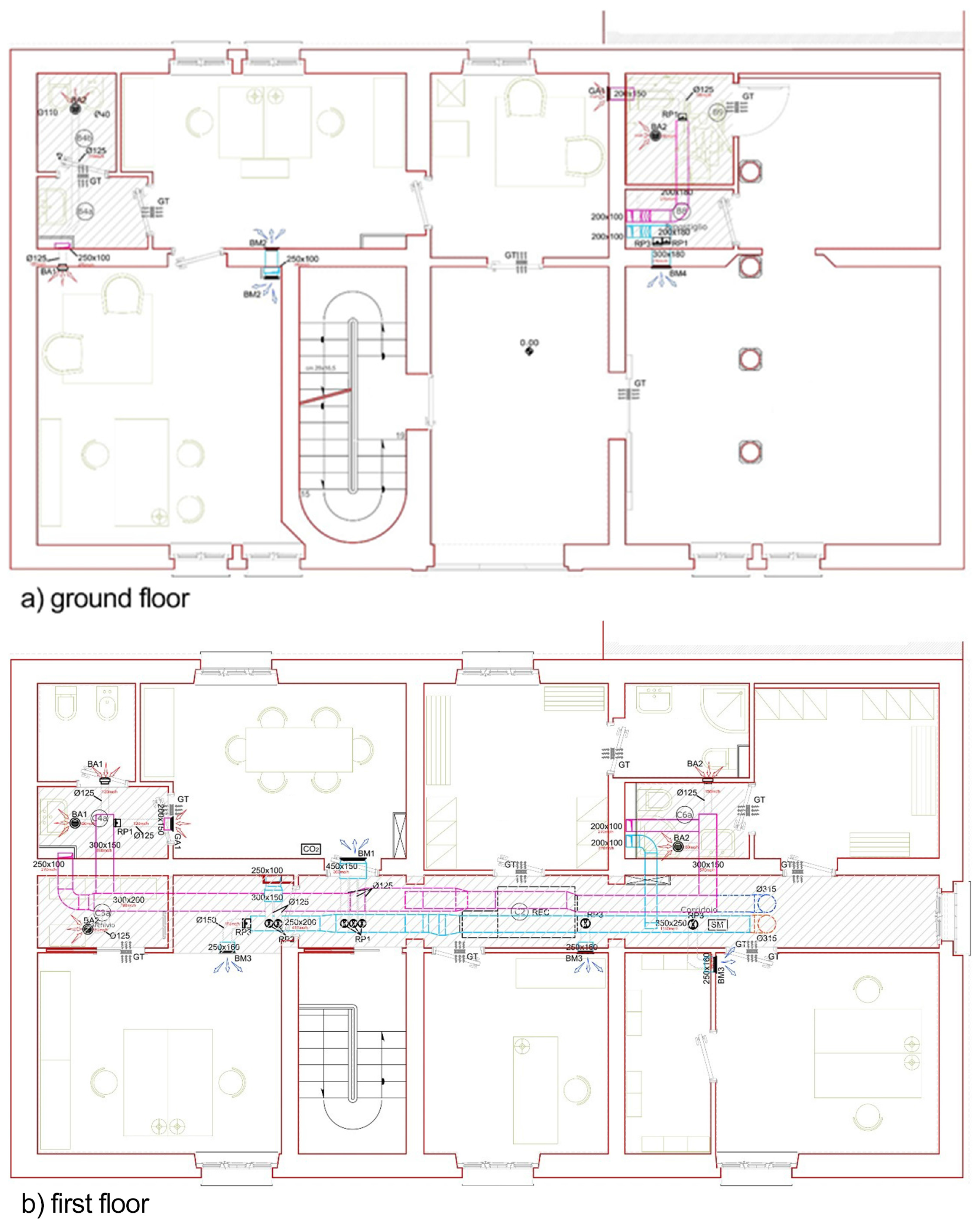
The case study consists of a two-storey building of about 140 m2 and a subterranean floor (Figure 2), which previously was used as the ancient stable of the complex. Currently, the retrofitted building is a university building and it hosts offices, laboratories, and conference rooms of an interuniversity research center working on the sustainable development of the built environment, i.e., CIRIAF (i.e., Interuniversity Research Center on Pollution and Environment ‘Mauro Felli’), and CRB (i.e., Biomass Research Center) of the University of Perugia, Italy. The stable was significantly damaged by the earthquake in 2009, therefore the roof, the ceiling, and the slabs were almost completely destroyed. For this reason, the whole structure of the building was reinforced and strengthened according to the local seismic regulations. Although a great part of the building components, such as beams, tiles, and bricks, were particularly damaged, it was possible to preserve most of the building materials, i.e., up to 20%, re-using them during the refurbishment process, which was carried out according to the GBC HB protocol. Table 2 summarizes the thermal-optical characteristics of the retrofitted building envelope components.
The old stable was not provided with any sort of energy systems before the retrofit. Therefore, the newly installed HVAC systems consist of an innovative prototype of a trigeneration plant powered by vegetable oil extracted by local biomasses of the area. Moreover, the building is provided by a mechanical ventilation system with heat recovery and two bio-digesters for bio-gas production. Therefore, the retrofitted stable, together with the rest of the buildings of the Sant’Apollinare complex, constitutes a sort of ‘eco-village’ based on the circular economy principles.
3.3. Retrofit Strategies Applied According to the GCB HB Protocol
After the implementation of the different retrofit strategies according to GBC Historic Building®, the building will host the offices and conference rooms of an International inter-university Research Centre focused on energy efficiency solutions for new and existing buildings by exploiting renewable energy sources. In greater detail, even if the building walls, roof, and slabs were considerably damaged after the earthquake of 2009, the retrofit process allowed to maintain most of the original load-bearing stone structures and the mixed wood-brick materials for the new pavements and ceilings. Moreover, a continuous external insulation layer was installed after the approval by the local Architectural Preservation Office. This was possible since the external continuous insulation layer is completely detached from the original building façade and, consequently, removable with no permanent consequences for the architecture. For this reason, i.e., for the total reversibility of the intervention, the local Architectural Preservation Office allowed to install the continuous insulation on the building external envelope, given that it does not affect or deteriorate the underlying historical façade. Moreover, the historic building envelope was originally plastered with a thin layer even if of course not thermally insulated, therefore the façade appearance was consistent with respect to the post-retrofit envelope configuration, and to the adjacent Rocca which has the same plaster finishing.
Therefore, the retrofit process consisted of the following main consecutive phases:
- preliminary structural strengthening;
- re-distribution of the indoor spaces;
- demolition and reconstruction of the roof, pavements and ceilings;
- repair of the building envelope and installation of the external bio-based continuous insulation;
- implementation of energy efficiency measures, i.e., cool roof-paving materials, renewable energy systems, etc.
Figure 3 and Figure 4 show the retrofit strategy adopted for the opaque building envelope (Figure 3a,b) and for the internal re-distribution of spaces and integration of building services (Figure 4).
All the different phases of the retrofit process have been carried out following the guidance provided by GBC Historic Building® within the framework of the different modules composed by prerequisites and credits.
As for the Historic Value module, the aim is to guarantee the maximum understanding of the current characteristics and performance of the building and to implement solutions which are compatible with the historic fabric, reversible and durable over time. In fact, it is necessary to maintain the original materials and architectural elements of the historic construction as much as possible in order to preserve its cultural value. To this regard, the present case study demonstrates consistency between the historic existing materials and the new materials, solutions and construction technologies used for the retrofit. In fact, most of the original materials (tiles, bricks and wood beams) and traditional building techniques were used as well for the refurbishment of the building. Additionally, in order to guarantee that the most appropriate and respectful retrofit process has been implemented, a Specialist in preservation of buildings and sites has collaborated with the project team during the different phases, as suggested in the protocol.
As concerning the Sustainable Sites, one of the aims of this module is reducing the impact of the activities carried out inside the construction site on the surrounding environment. To fulfil the requirements of the prerequisites and credits of this module, different precautions have been applied during the building retrofit. First, the construction team has been educated to follow the protocol’s requirements by means of dedicated training courses. Then, the main pollution sources have been identified and confined not to damage the surrounding context. Moreover, additional several strategies have been applied to prevent the construction site activities from affecting the environment. For instance, a dedicated area easily accessible to the public transportation was arranged, a parking space for bicycles and electric/carpool/vanpool vehicles was provided and changing rooms for the workers were set up. Finally, the installation of highly-reflective materials both on the building roof and on the outdoor pavement was performed as mitigation strategy against local environmental phenomena such as urban heat island [20]. In particular, cool tiles and cool aggregates characterized by a SRI of 47, 45, and 47 respectively, were applied on (i) the roof and (ii) the outdoor pavement in the proximity of the building. More in details, the installed cool tiles consist of innovative and prototype clay tiles specifically developed by the same authors for specific application in historical buildings, characterized by the same external appearance of historical tiles but characterized by high solar reflectance capability [9]. As regarding the cool aggregates, which were used to cover the outdoor pavement, they consist of white-colored gravels produced in a quarry nearby the building site with optimized grain size for increasing their albedo value. Therefore, previous works by the same authors demonstrated that the albedo of commonly used gravels increase with the decrease of the grain size [21].
For the Water Efficiency module, several solutions have been applied to reduce the consumption of potable water as much as possible. In particular, a tank for the collection of rainwater has been installed. Moreover, no use of potable water is needed for irrigation purposes, since specific species of greenery not needing constant watering were selected. Finally, 100% of the drained water is treated on site.
As for the Energy and Atmosphere module, the aim is improving the building thermal-energy performance and encouraging the use of renewable energy sources. In order to meet the requirements of this module, the dynamic simulation of the pilot case study building was carried out in EnergyPlus environment according to the indication of the Appendix G of the ASHRAE 90.1-2007 [22]. Therefore, a reference building and a design building have been simulated and compared in terms of primary energy requirements.
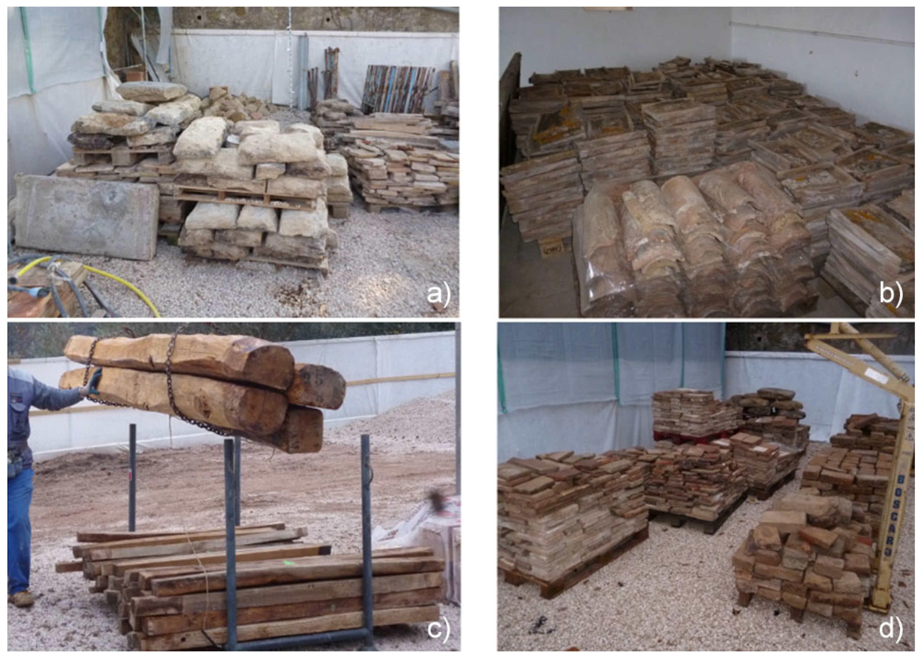
For achieving the prerequisites and credits of the Materials and Resources module, it is necessary to perform a proper selection of low-impact and sustainable building materials and to elaborate plans for their disposal. Therefore, in the case of the pilot case study, natural building materials locally provided and with about 5% of recyclable components were selected. For this reason, the materials account for only the 21% of the total costs of the building retrofit. In fact, most of the tiles, stones, bricks and wooden beams previously located in the building were reused during the retrofit (Figure 5).
As concerns the Indoor Environmental Quality module, it was necessary to provide a detailed management IAQ plan and to perform all the different activities by following the indications of such plan during the whole construction phase. In particular, the storage of materials in the construction site was organized in order to guarantee its integrity up to the time of installation and to avoid the production of waste due to possible damage. More in details, the following best practices have been adopted:
- the materials were positioned and kept raised from the ground using pallets, or stored in pipelines to be protected against moisture and accumulation of dirt;
- the deposited materials were properly covered;
- the building was closed by setting up temporary closures using plastic or wood to prevent the accumulation of moisture inside the building;
- any accumulation of water inside the building was immediately removed to protect the building surfaces and the interior materials already installed.
Furthermore, to preserve the quality of the indoor environment, none of the construction materials and of the sealing, glues, cements, or products used during the construction phase exceed the VOC limits imposed by the protocol.
Moreover, a detailed calculation of the air changes to be provided in each room of the building by the mechanical ventilation system was carried out based on the number of occupants and the minimum requirements according to the current local regulation 10339 [23].
In order to guarantee a proper indoor environmental quality as required by the protocol, each room was additionally equipped with control systems of (i) the ambient temperature and (ii) the lighting level. Additionally, in three representative rooms of the building, microclimate monitoring stations were installed. In particular, the sensors are able to continuously collect the indoor air temperature (°C), mean radiant temperature (°C), relative humidity (%), air velocity (m/s), illuminance level (lux), the air quality in terms of CO2, VOC, CO (ppm). Such experimental equipment allows to control and manage the indoor environmental quality of the indoor building environment, since it also allows detecting any systems malfunctioning or damage. Additionally, between 6–18 months of occupancy of the building a detailed survey about the indoor thermal comfort will be carried out among the occupants.
3.4. The Dynamic Thermal-Energy Simulation
The prediction of the case study’s primary energy requirements was performed within the DesingBuilder interface (version 3.4) of the EnergyPlus (version 8.1) dynamic simulation environment. Following the requirements of GBC Historic Building®, two building models were implemented, i.e., a “baseline” and a “design” building models (Figure 6). The final purpose was to quantify the energy performance improvement in terms of total primary energy consumption. While the design building model was implemented by considering the final retrofitted configuration of the building in terms of position, orientation, building materials, energy systems and occupancy pattern, the reference building model was elaborated by following the Appendix G of the ASHRAE standard 90.1-2007. Therefore, this second model refers to all the different possible orientations and to “default” building envelope features, HVAC systems, etc., as indicated by the above-mentioned standard.
4. Results and Discussion
In this section, the GBC Historic Building® protocol application is discussed more in details. Globally, the major renovation interventions consisted of the design and application of:
- (1)
- a high-performance building envelope, by considering the specifications provided by the local Architectural Preservation Office;
- (2)
- a new effective HVAC energy system, by implementing an innovative prototype trigeneration renewable energy plant.
In the following subsections, the tailored retrofit solutions concerning (i) the high-albedo materials applied on the building envelope and pavements and (ii) the pilot trigeneration plant are described. Moreover, the prerequisites and credits achieved by category in the case study building are discussed in detail. Finally, the energy performance improvement achieved is described.
4.1. High-Albedo Materials Counteracting Urban Heat Island
As mentioned in the previous sections, the application of highly-reflective materials for passive cooling purposes represents one of the main retrofit actions carried out in the pilot case study. This is due to the fact that one of the main requirement of GBC Historic Building® is to implement solutions for the mitigation of local microclimate phenomena such as the urban heat island. For building roofs with a slope >15%, as in the present case study, the protocol requires to apply materials with a Solar Reflection Index (SRI) [24] >29 in at least the 75% of the total roof surface. To this aim, a dedicated in-lab measurement campaign to determine the solar reflectance and thermal emissivity of the existing roofing materials was carried out by means of (i) a spectrophotometer Solid Spec C3700, according to the ASTM Standard G173-03 [25], and (ii) a portable thermal emissometer AE1 RD1, according to the ASTM Standard C1371-04 [26]. More in details, the original roof (Figure 7) was constituted by both shingles and tiles, characterized by different surface characteristics and top layer finishing due to the degradation over time. Therefore, several and different samples of shingles (Figure 8a) and clay tiles (Figure 8b) were selected and tested in laboratory. Additionally, for each sample, at least four different points of the surface were measured in order to get reliable results as required by the above-mentioned regulations. In particular, Figure 8a,b—1), 2), 3), 4) summarizes the different solar reflectance values measured in the four different surface points. Therefore, the final value is the average of the four measurements over the shingle/tile surface. Moreover, a sample of tile for each roof surface orientation was selected and tested. The results of the measurement campaign are summarized in Table 3.
Moreover, innovative local, natural, low-cost, and low-environmental impact gravels supplied by a quarry located a few kilometers from the buildign site (i.e., <50 km) were used to cover the outdoor buildign paved area (Figure 9). Such gravels can be consideres as cool since they were optimized and test both in laboratory, by menas of specthophotometer and thermal-emissometer, and in-field by means of albedometers, in terms of albedo. More in details, the grains size of the gravles was minimized in order to achieve a better albedo, i.e., up to , since it was demonstrated that the albedo increases by decreasing the size of the grains.
4.2. Renewable Energy Plant
The main interventions related to the building mechanical systems are constituted of:
- winter and summer air-conditioning system powered by a district heating sub-station and provision of a district cooling sub-station in the building;
- winter and summer air-conditioning system with underfloor heating and mechanical ventilation system to control the indoor relative humidity and air-renewal;
- plumbing system powered by the district heating sub-station and the rainwater/black water drainage network.
The present section concerns the detailed description of such innovative and high-performing energy systems, with particular attention to the energy grid composed of integrated biomass plants.
More in details, the installed biomass plants are:
- a mechanical seeds milling plant;
- a tri-generation CHP engine (i.e., Combined Heat and Power);
- a small size bio-gas plant.
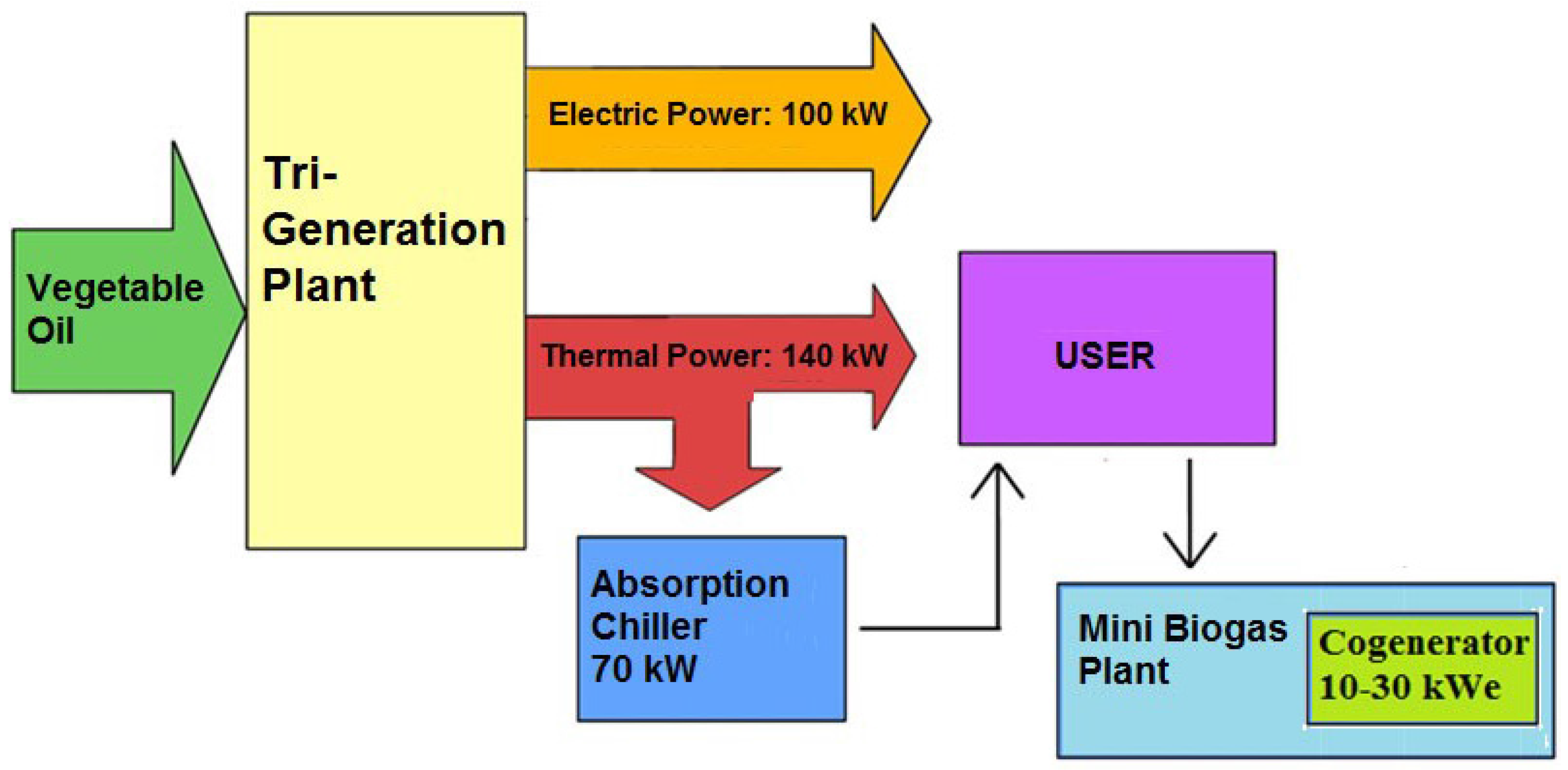
The thermal needs and the cooling requirements of the buildings of the ancient monastery can be completely covered by the tri-generation CHP engine, fed by the vegetable oil from the milling of the seeds from the cultivated fields (sunflowers, rapeseeds) close to the village. The engine is connected to an absorption chiller to produce cooling for summer conditioning via the district net. All the produced electricity is conferred to the national electric grid in order to operate an exchange with the consumed electricity. The residues from the mill can be enhanced to energy through the anaerobic digestion in the bio-gas plant, together with the organic waste residues from the buildings and the wastewater from the sewers (Figure 10).
The circular economy concepts [27] on which the whole project is based require all residues and waste produced in the village to be reused for the production of new energy or matter. Minimizing the final products means reducing the impact on the environment. In particular, the sustainability of the pathway to produce vegetable oil has been implemented by cultivating cardoon crops (Cynara Cardunculus) [28]. It is a multiannual cultivar producing seeds that can be easily harvested using grain machines. This crop is sustainable because it is a low water and energy crop. It is spontaneous, not to be watered or requiring additional treatments (as fertilizers) and it can be planted in the abundant abandoned and marginal lands, avoiding the competition with food crops.
The milling plant is composed of: a preliminary system for seeds weighing and loading, vibrating sieves to separate husks and leaves, a mechanical press, an oil filtration section. The storage: two 50 m3 tanks for oil and two 90 m3 silos for seeds (Figure 11). The yield is about 100 kg/h in oil and 200 kg/h in cardoon squeezing residue.
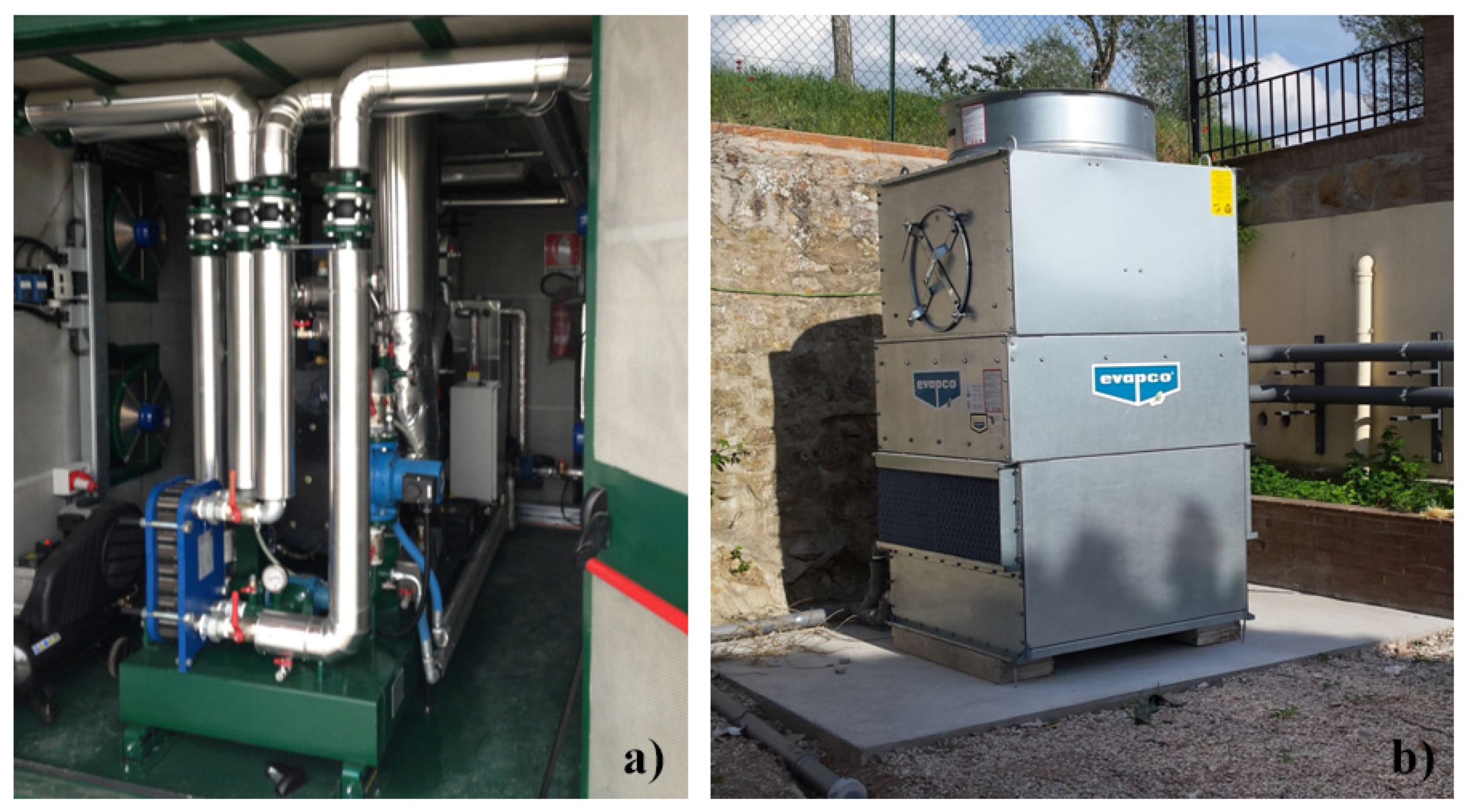
The tri-generation CHP engine works up to 7,000 h per year and its electric power is 100 kW. The oil consumption is about 25 kg/h. The thermal power is about 140 kW and the cooling plant (an absorption chiller) is 70 kWf (Figure 12). The sizes were previously defined after the analysis of the thermal and cooling energy loads and the energy requirements of the served village.
The bio-gas plant is about 30 kW powered and the 50-kW thermal power is spent to heat the three digesters, 7 m3 each, working in mesophilic conditions (40 °C). The exceeding heating can be energy. The system is completely automatic and managed by sensors for biomass levels, temperature, pH, and bio-gas pressure. The digested material has been ejected by the plant to a drainage tank where the aerobic stabilization occurs. The whole cardoon pathway is correctly closed because the digestion residue can be spread out to the same field where new biomass is produced.
The prototype plant supplies the whole complex of Sant’Apollinare; therefore, only the 29% of the total power provided by the system supplies the case study building.
The four-district heating and cooling piping supplying the complex are characterized by the presence of heat meters to distinctly account for the energy consumption of the different buildings.
The indoor units are constituted of underfloor heating and radiators. An auxiliary heating system constituted by a 500-L boiler powered by a direct break from the district heating pipe is provided in case of maintenance of the trigeneration plant.
The building is also equipped with a controlled mechanical ventilation system with heat recovery according to the standard UNI EN 15251 [29]. The plant was sized according to the building surface and the number of occupants to ensure the proper air change and dehumidification in the summer period. Such system provides a 1350 m³/h flow rate and it is managed through a system of ducts and inlets placed in the different building areas, while the exhaust air intake takes place mainly in the toilets through the intake vents (Figure 4). The pipes arrive directly in the building basement, where the substation providing the distribution of the heating, cooling and domestic hot water is positioned. The air velocity in the channels is less than 2 m/s to avoid noise-related issues. The centerpiece of the mechanical ventilation system is the air handling units with dual-flow heat exchanger and heating battery post-hydronic cooling. The unit has a water coil with a 8.8 kW cooling capacity able to (i) heat up in winter and cool down in summer the incoming air and (ii) avoid the underfloor heating surface condensation. The regulation of the energy recovery is expected at 20 °C in summer and winter; the summer/winter changeover takes place via thermostat placed on the collector and calibrated at 30 °C. With an outside temperature range of 20°C ÷ 25°C, the battery unit is deactivated and the air is injected into at neutral temperature environment.
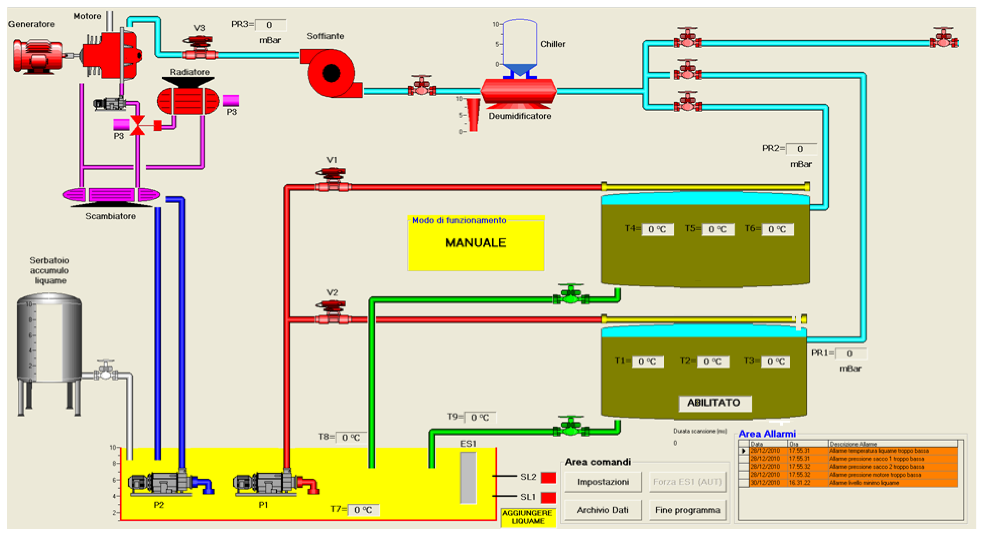
Lastly, in order to promote a circular economy principle for the case study building, which is part of a sort of small eco-village, a small bio-gas plant is installed in the building for the waste water/black water purification by anaerobic digestion. It is constituted by three underground facilities, i.e., a hydrolyser (7 m3), a first digester (7 m3) and a second digester (7 m3) powered by a 10 kW machine (Figure 13). A dedicated management system for the control of the small bio-gas plant operation is also provided (Figure 14).
4.3. GBC Historic Building® Protocol Application
The achieved prerequisites and credits for each category of the GBC Historic Building® in the case study building are summarized in Table 4.
A GBC Historic Building® Accredited Professional (GBC HB AP) supervised and guided the whole certification process in order to optimise the achievement of credits in each category according to the available points allocated in the certification manual for each credit. Therefore, the total certification score depends on the level of satisfaction of the requirements against the threshold defined in the GBC HB manual. For instance, in our specific case study:
- in the HV category, the maximum available score (i.e., 2 points) was achieved in Credit 2 for implementing >60% reversible interventions on the building structure. Moreover, 1 point out of the available 2 points is achieved in Credit 3.1 since more than 10% of the surface is dedicated to public uses. Finally, the maximum 1 point available in Credit 4 is achieved for meeting the sustainability principles applied during the construction phase;
- in the SS category, the maximum 1 point achievable is gained in each of the transportation-related credits, i.e., Credit 2.1, Credit 2.2, Credit 2.3 and Credit 2.4 for providing access to public transportation (i.e., bus), bycicle storage spot/changing rooms for user and parking area for fuel-efficient vehicles in the building outdoor/indoor area. Moreover, the maximum achievable 2 points of Credit 4 are assigned to the case study building due to the management of water quality and quantity by minimizing its waste and use in outdoor green areas. Consitently, the maximum achievable 2 points for Credit 5 are reached since highly-reflective materials were installed both over the building envelope surfaces (i.e., roof and facades) and on the outdoor paving to contribute to the mitigation of the urban heat island effect;
- in the WE category, the case study achieved the maximum 3 points available in Credit 1 since no water was used for irrigation purposes. Morevoer, the maximum available 3 points are gained in Credit 2 due to a total water saving up tp more than 40% reached in the building. Finally, only 1 point out of the maximum 2 available is achieved for Credit 3. This is motivated by the fact that the building is not equipped with water metering for every appliance of the building.
- in the EA category, the maximum achievable 17 points for Credit 1 are gained as the building reached up to a 40% primary energy saving. As for Credit 2, since in the case study building all of the renewable enery is produced in site, the maximum 6 points available are achieved. In Credit 3, Credit 4 and Credit 5, the maximum points are achieved (i.e., 2, 1 and 3 points, respectively) due to the advanced energy commissioning that was carried out, the absence of refrigerant fluids and the elaboration of a detailed measurement and verification plan.
- In the MR category, the maximum 2 points available are achieved in Credit 3 due to the fact that more than 15% of materials were recycled. Morevoer, in Credit 4 the maximum score is achieved (i.e., 5) since the total cost of the materials in the retrofit project accounts for about 50% of the total cost. Finally, only 1 point out of the maximum achievable 2 points is gained in Credit 5 due to the fact that more than 40% of the installed materials was produced within an area distant 180 Km from the construction site.
- In the EQ category, for Credit 1 and Credit 2 the maximum reachable 2 points are achieved due to indoor air monitoring and mimimum fresh air provided inside the building by regulation. The same happens for Credit 3.1 and Credit 3.2, where the maximum achievable 1 point is assigned to the case stduy building based on the elaboration and application of a IAQ detailed management plan, both during and after construction. As regarding Credit 4.1, Credit 4.2, the maximum achievable score (i.e., 1) is gained due to the implementation of non-toxic and low-emitting materials in the building. Credit 6.1 and Credit 6.2 achieve the maximum 1 available point each since a monitoring system of the thermal and visual comfort is provided in the building. Finally, the maximum available 1 point is reached in Credit 7.1 for the carefull design of thermal comfort conditions for the occupants of the building. Morevoer, the maximum 2 points available are achieved in Credit 7.2 since a dedicated post-occupancy monitoring, survey, and verification of the occupants’ comfort conditions is carried out;
- As for the ID category, 4 points out of the maximum achievable 5 points are scored in Credit 1 since 4 different innovative solutions are proposed to be implemented in the certification protocol. Morevoer, the maximum 1 available point is scored in Credit 2 since a professional and certified GBC HB consultant (GBC HB AP) was involved in the project from the very beginning to review and guide all the process;
- As for the RP category, the maximum 4 achievable points are all gained in the present pilot case study based on the significance of the achieved credits with respect to the regional environmental priorities of the area.
4.4. Energy Performance Improvement
The purpose of the dynamic energy simulation is to highlight the improvement achieved in terms of energy performance after the implementation of all the retrofit strategies.
The model of the “design” building was implemented according to the real design choices carried out. However, since it was not possible to model the real features of the innovative pilot trigeneration plant, the “extraordinary calculation method” provided by the LEED® v4 [17] guidelines were used to model an equivalent energy system able to best approximate the characteristics of the real plant. Therefore, the modelled energy plant in the design building is a 125 kW fuel oil boiler supplying (i) the underfloor heating and radiators installed in the building and (ii) a 0.5 m3 DHW heater. As for the cooling system, an equivalent 70 kW condensation chiller was modelled. The total DHW flow rate is 490 L/day according to the UNI 9182:2014, Appendix E) [30].
On the contrary, the model of the “baseline” building was elaborated according to the ASHRAE 90.1:2007, Appendix G [22]. Such additional building model was created in order to calculate the energy performance improvement (%) generated by the implementation of the retrofit strategies in the design building. In this case, the simulation was performed in all the different four orientation of the building. Moreover, the standard requires to model either the existing building envelope features, i.e., before the retrofit, or to follow the prescriptions of the 192/2005 Legislative Decree [31]. In this case, since the original building was damaged and the structure was almost destroyed, the thermal transmittance values selected were the maximum as indicated by both the 192/2005 Decree and the ASHRAE 90.1 2007 (Appendix G). Moreover, the opening percentage was set as to be the minimum value between the real value of the design building and the 40% of the whole building opaque envelope surface. No shading is required by the above-mentioned regulations. The lighting systems were modelled based on the Building Area Method of ASHRAE 90.1:2007. The HVAC systems were determined according to the surface, the activities, the floors number and the heating energy source of the design building by using the tables G.3.1.1.A e G.3.1.1.B from ASHRAE 90.1-2007. Therefore, a 125 kW fuel oil boiler was modelled as in the design building. The air flow-rate is the same as the design building, i.e., 10 L/s per person. The occupancy schedule profiles, consisting of the typical schedule for office buildings, are the same for both models. In both buildings, the same mechanical ventilation system and the DHW system are modelled.
In order to compute the primary energy requirements, the conversion factors for electricity (i.e., 2.28), for natural gas (i.e., 1) and for the fuel oil (i.e., 1.35) are used according to the UNI EN 15603:2008 [32]. The primary energy need calculated by multiplying the simulation output for the conversion factors represents therefore the design building energy performance.
The regulatory energy includes the lighting (indoor and outdoor), the HVAC systems (heating, air-conditioning, ventilation, pumps, etc.) and the DHW. The simulation results show an overall performance improvement after the retrofit of the building. Table 5 and Table 6 show the comparison between the design building and the baseline building simulation outputs in terms of monthly primary energy consumption separated by final usage.
5. Conclusions
The present work consisted of the proposal of an integrated approach for the restoration of heritage buildings by means of combined passive and active retrofit strategies. In particular, a historic building located in central Italy was selected as pilot case study for the application of a holistic refurbishment approach in terms of achievable energy performance enhancement. This innovative retrofit approach is based on the application of the principles of a newly developed certification protocol, i.e., GBC Historic Building®, tailored for the application to heritage constructions, which typically need not only an upgrade in terms of structural resilience but also in terms of thermal-energy performance.
The main retrofit intervention applied consists of (i) the installation of a pilot trigeneration plant exploiting renewable energy sources and (ii) the application of innovative passive cooling materials on both the building roof and outdoor pavement.
Moreover, the dynamic energy simulation of the building in two different configurations, i.e., pre-retrofit and post-retrofit, showed an overall energy performance enhancement by about 40%.
Acknowledgments
A.L. Pisello’s acknowledgments are due to the UNESCO Chair “Water Resources Management and Culture”, for supporting her research. The project leading to this application has received funding from the European Union’s Horizon 2020 research and innovation programme under grant agreement No 700395 (HERACLES) and from the European Union’s Horizon 2020 research and innovation programme under grant agreement No 678407 (ZERO-PLUS).
Author Contributions
Franco Cotana and Anna Laura Pisello conceived and designed the experiments; Anna Laura Pisello and Veronica Lucia Castaldo performed the experiments; Veronica Lucia Castaldo and Alessandro Petrozzi analyzed the data; Anna Laura Pisello and Paola Boarin contributed to the analysis tools. All the authors gave a significant contribution in the paper’s writing process.
Conflicts of Interest
The authors declare no conflict of interest.
References
- CRESME. Riuso 2012; Cresme Ricerche: Roma, Italy, 2012. [Google Scholar]
- Carbonara, G. Energy efficiency as a protection tool. Energy Build. 2015, 95, 9–12. [Google Scholar] [CrossRef]
- De Santoli, L. Guidelines on energy efficiency of cultural heritage. Energy Build. 2015, 86, 534–540. [Google Scholar] [CrossRef]
- Ubertini, F.; Comanducci, G.; Cavalagli, N.; Pisello, A.L.; Materazzi, A.L.; Cotana, F. Environmental effects on natural frequencies of the San Pietro bell tower in Perugia, Italy, and their removal for structural performance assessment. Mech. Syst. Signal Process. 2017, 82, 307–322. [Google Scholar] [CrossRef]
- Roberti, F.; Oberegger, U.F.; Lucchi, E.; Troi, A. Energy retrofit and conservation of a historic building using multi-objective optimization and an analytic hierarchy process. Energy Build. 2017, 138, 1–10. [Google Scholar] [CrossRef]
- Ubertini, F.; Materazzi, A.L.; D’Alessandro, A.; Laflamme, S. Natural frequencies identification of a reinforced concrete beam using carbon nanotube cement-based sensors. Eng. Struct. 2014, 60, 265–275. [Google Scholar] [CrossRef]
- Ferrari, C.; Muscio, A.; Siligardi, C.; Manfredini, T. Design of a cool color glaze for solar reflective tile application. Ceram. Int. 2015, 41, 11106–11116. [Google Scholar] [CrossRef]
- Pisello, A.L. Thermal-energy analysis of roof cool clay tiles for application in historic buildings and cities. Sustain. Cities Soc. 2015, 19, 271–280. [Google Scholar] [CrossRef]
- Pisello, A.L.; Castaldo, V.L.; Pignatta, G.; Cotana, F. Integrated numerical and experimental methodology for thermal-energy analysis and optimization of heritage museum buildings. Build. Serv. Eng. Res. Technol. 2016, 37, 334–354. [Google Scholar] [CrossRef]
- Pisello, A.L.; Petrozzi, A.; Castaldo, V.L.; Cotana, F. On an innovative integrated technique for energy refurbishment of historical buildings: Thermal-energy, economic and environmental analysis of a case study. Appl. Energy 2016, 162, 1313–1322. [Google Scholar] [CrossRef]
- Galatioto, A.; Ciulla, G.; Ricciu, R. An overview of energy retrofit actions feasibility on Italian historical buildings. Energy 2016. [Google Scholar] [CrossRef]
- European Parliament and Council. Directive 2012/27/EU of 25 October 2012 on energy efficiency, amending Directives 2009/125/EC and 2010/30/EU and repealing Directives 2004/8/EC and 2006/32/EC. 2012. Available online: http://eur-lex.europa.eu/legal-content/en/TXT/?uri=celex%3A32012L0027 (accessed on 31 March 2017).
- Green Building Council Italia; U.S. Green Building Council. Green Building Nuove Costruzioni e Ristrutturazioni. Sistema di Valutazione LEED NC 2009 Italia, 2nd ed.; Green Building Council Italia: Rovereto, Italy, 2011. [Google Scholar]
- Boarin, P.; Guglielmino, D.; Zuppiroli, M. Certified sustainability for heritage buildings: development of the new rating system GBC Historic Building™. Int. J. Sustain. Constr. 2014, 2, 7–17. [Google Scholar]
- Franceschini, F. Atti e Documenti della Commissione d’Indagine per la Tutela e la Valorizzazione del Patrimonio Storico, Archeologico, Artistico e del Paesaggio; Colombo: Roma, Italy, 1967. [Google Scholar]
- Green Building Council Italia. GBC Historic Building. Sistema di Verifica GBC Historic Building®—Parte 1; Green Building Council Italia: Rovereto, Italy, 2014. [Google Scholar]
- U.S. Green Building Council. LEED® Reference Guide for Design and Construction v4; U.S. Green Building Council: Washington, DC, USA, 2013. [Google Scholar]
- Boarin, P. Bridging the gap between environmental sustainability and heritage preservation: towards a certified sustainable conservation, adaptation and retrofitting of historic buildings, Revisiting the Role of Architectural Science in Design & Practice, Proceedings of the 50th International Conference of the Architectural Science Association, Adelaide, SA, Australia, 7–9 December 2016; Zuo, J., Daniel, L., Soebarto, V., Eds.; The University of Adelaide: Adelaide, Australia; pp. 675–684. ISBN 978-0-9923835-3-4.
- Lucchi, E.; Boarin, P.; Zuppiroli, M. Assessing environmental sustainability and energy efficiency of historic buildings: a new certification tool for delivering cultural values in renovation processes. In Proceedings of the 2nd International Conference on Energy Efficiency and Comfort of Historic Buildings (EECHB 2016), Brussels, Belgium, 19–21 October 2016. [Google Scholar]
- Castaldo, V.L.; Coccia, V.; Cotana, F.; Pignatta, G.; Pisello, A.L.; Rossi, F. Thermal-energy analysis of natural “cool” stone aggregates as passive cooling and global warming mitigation technique. Urban Clim. 2015, 14, 301–314. [Google Scholar] [CrossRef]
- Boarin, P.; Guglielmino, D.; Pisello, A.L.; Cotana, F. Sustainability assessment of historic buildings: Lesson learnt from an Italian case study through LEED® rating system. Energy Procedia 2014, 61, 1029–1032. [Google Scholar] [CrossRef]
- ASHRAE 90.1-2007, Appendix G Building Performance Rating Method; U.S. Department of Energy, Office of Energy Efficiency and Renewable Energy: Washington, DC, USA, 2007.
- UNI—Ente Italiano di Normazione. Impianti Aeraulici al Fine di Benessere. Generalità, Classificazione e requisiti. Regole per la Richiesta d’Offerta, l’Offerta, l’Ordine e la Fornitura; Standard UNI 10339; UNI: Milano, Italy, 1995. [Google Scholar]
- Yuan, J.; Emura, K.; Farnham, C.; Sakai, H. Application of glass beads as retro-reflective facades for urban heat island mitigation: Experimental investigation and simulation analysis. Build. Environ. 2016, 105, 140–152. [Google Scholar] [CrossRef]
- American Society for Testing and Materials. Standard Tables for Reference Solar Spectral Irradiances: Direct Normal and Hemispherical on 37° Tilted Surface; ASTM G173-03(2012); ASTM International: West Conshohocken, PA, USA, 2012. [Google Scholar]
- American Society for Testing and Materials. Standard Test Method for Determination of Emittance of Materials Near Room Temperature Using Portable Emissometers; ASTM C1371-04 (2004); ASTM International: West Conshohocken, PA, USA, 2004. [Google Scholar]
- European Commission. Closing the Loop—An EU Action Plan for the Circular Economy; COM614; European Commission: Brussels, Belgium, 2015. [Google Scholar]
- Cavalaglio, G.; Petrozzi, A.; Coccia, V.; D’Antonio, S.; Cotana, S. Mass and energy flows of cardoon oil in a prototype system for seeds milling and vegetable oil treatment and cogeneration. Energy Procedia 2015, 82, 681–685. [Google Scholar] [CrossRef]
- UNI—Ente Italiano di Normazione. Criteri per la Progettazione dell’Ambiente Interno e per la Valutazione della Prestazione Energetica Degli Edifici, in Relazione alla Qualità dell’Aria Interna, all’Ambiente Termico, all’Illuminazione e all’Acustica; Standard UNI EN 15251; UNI: Milano, Italy, 2008. [Google Scholar]
- UNI—Ente Italiano di Normazione. Impianti di Alimentazione e Distribuzione d’Acqua Fredda e calda—Progettazione, Installazione e Collaudo; Standard UNI 9182; UNI: Milano, Italy, 2014. [Google Scholar]
- Decreto Legislativo 19 Agosto 2005, n. 192. Attuazione della direttiva 2002/91/CE relativa al rendimento energetico nell’edilizia. Available online: http://www.camera.it/parlam/leggi/deleghe/05192dl.htm (accessed on 31 March 2017).
- UNI—Ente Italiano di Normazione. Prestazione Energetica Degli Edifice—Consumo Energetico Globale e Definizione dei Metodi di Valutazione Energetica; Standard UNI EN 15603; UNI: Milano, Italy, 2008. [Google Scholar]
Figure 1.
Geographic location (a) and identification of the different buildings in the complex of Sant’Apollinare (b), Perugia, Italy.
Figure 1.
Geographic location (a) and identification of the different buildings in the complex of Sant’Apollinare (b), Perugia, Italy.

Figure 2.
Architectural drawings of the case study building. Existing section (up left and bottom left) and sections of the retrofit solution (up right and bottom right).
Figure 2.
Architectural drawings of the case study building. Existing section (up left and bottom left) and sections of the retrofit solution (up right and bottom right).
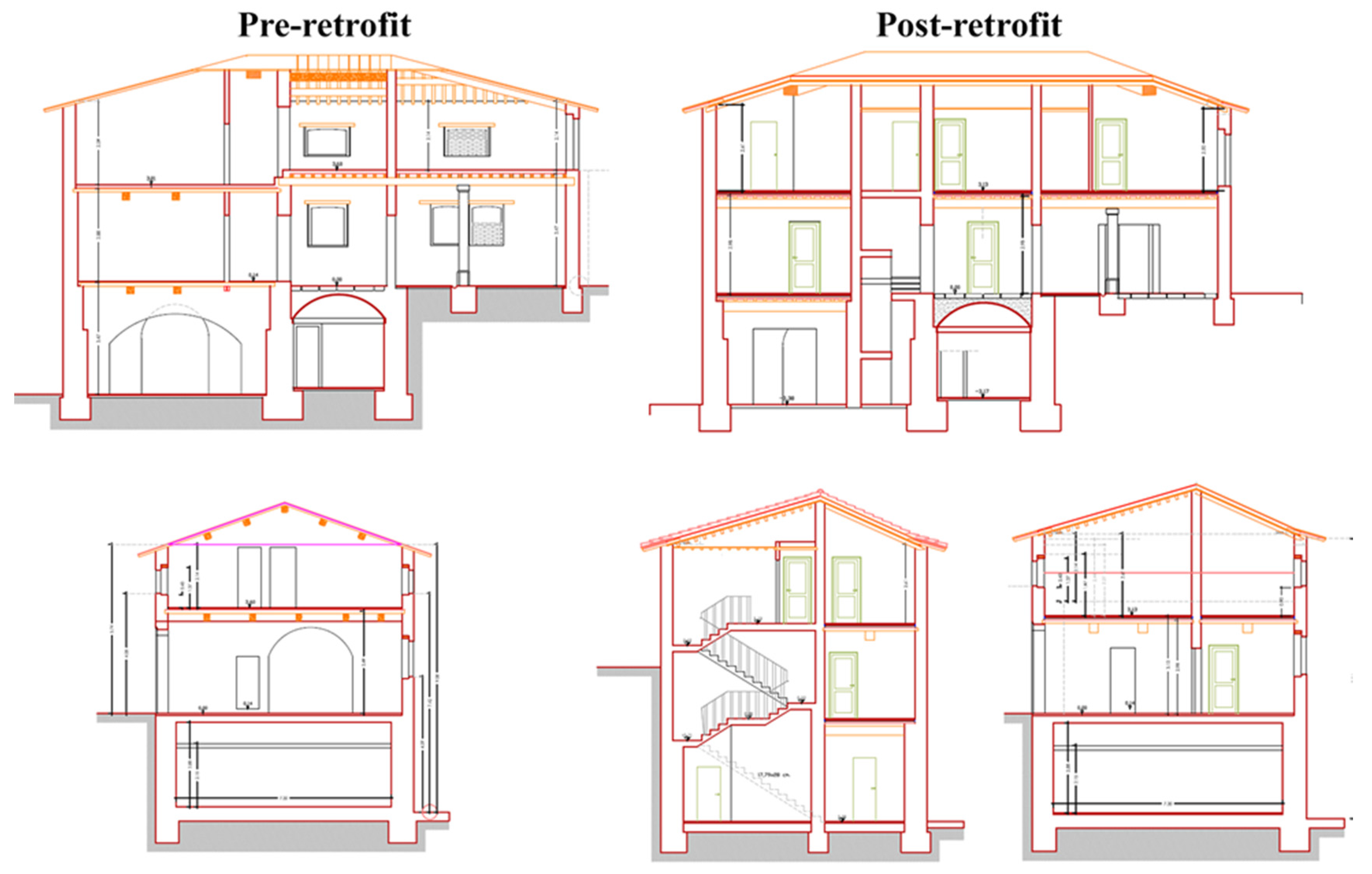
Figure 3.
Comparison between the historic pilot case study building (a) before (i.e., only historic picture available, after the thin layer of external plaster had already been detached) and (b) after the retrofit.
Figure 3.
Comparison between the historic pilot case study building (a) before (i.e., only historic picture available, after the thin layer of external plaster had already been detached) and (b) after the retrofit.
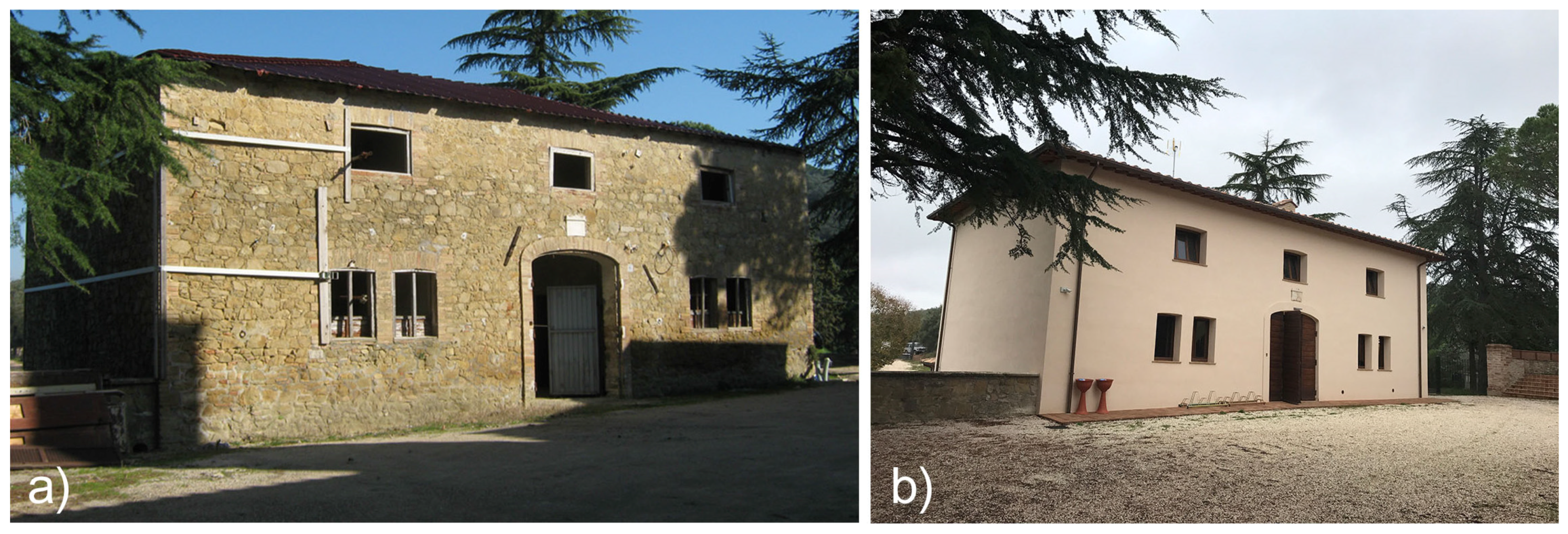
Figure 4.
Reorganization and re-distribution of the indoor spaces on the first floor of the building. (a) ground floor; (b) first floor.
Figure 4.
Reorganization and re-distribution of the indoor spaces on the first floor of the building. (a) ground floor; (b) first floor.

Figure 5.
Existing materials found in the historic building and reused during the refurbishment: (a) recycled stones; (b) recovered roof tiles; (c) rescued wooden beams; and (d) recycled original bricks.
Figure 5.
Existing materials found in the historic building and reused during the refurbishment: (a) recycled stones; (b) recovered roof tiles; (c) rescued wooden beams; and (d) recycled original bricks.

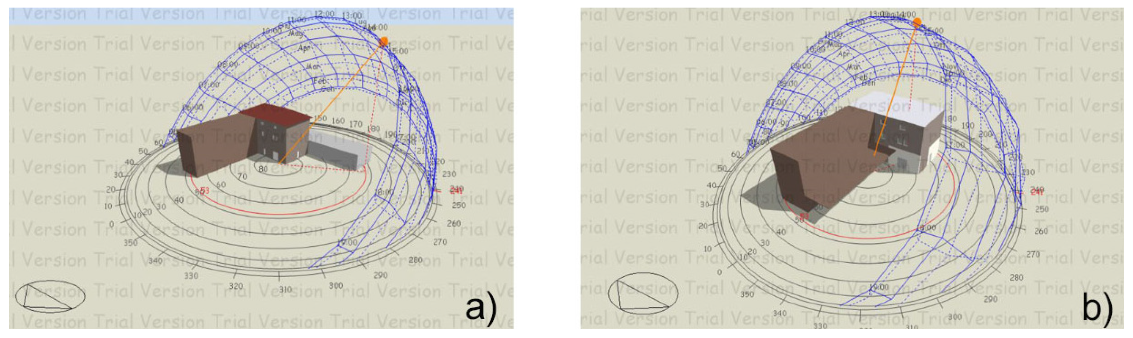
Figure 6.
Models of the reference building (a) and of the design building (b) implemented within the DesignBuilder-EnergyPlus simulation tool.
Figure 6.
Models of the reference building (a) and of the design building (b) implemented within the DesignBuilder-EnergyPlus simulation tool.

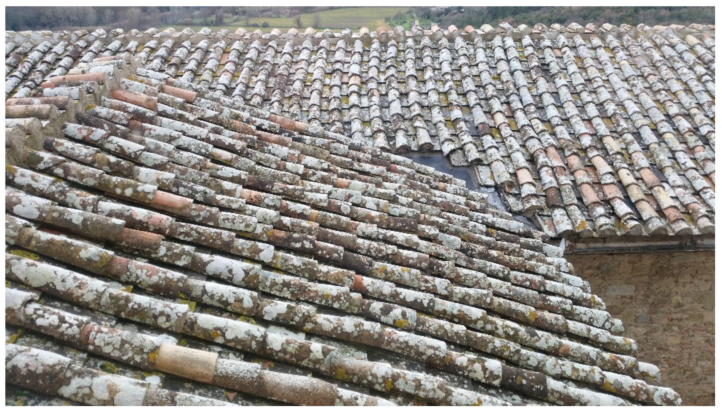
Figure 7.
View of the case study’s roof with the original tiles.

Figure 8.
Measurement points over each tested sample.
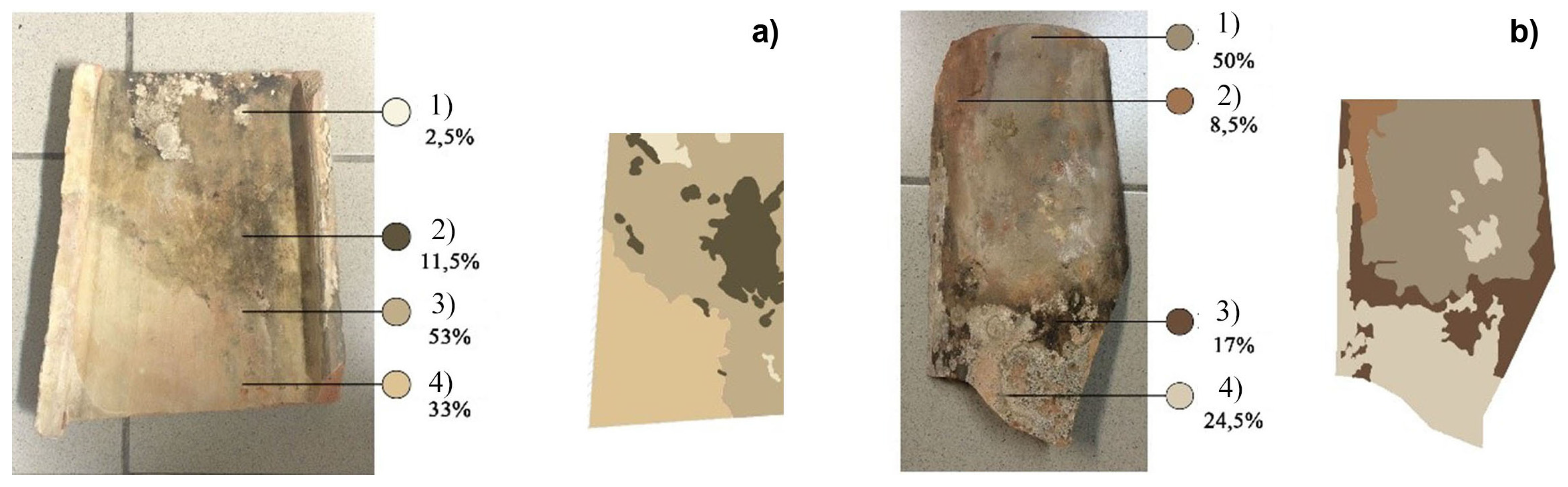
Figure 9.
Views (a,b) of the building outdoor paved area covered by high-albedo gravels.
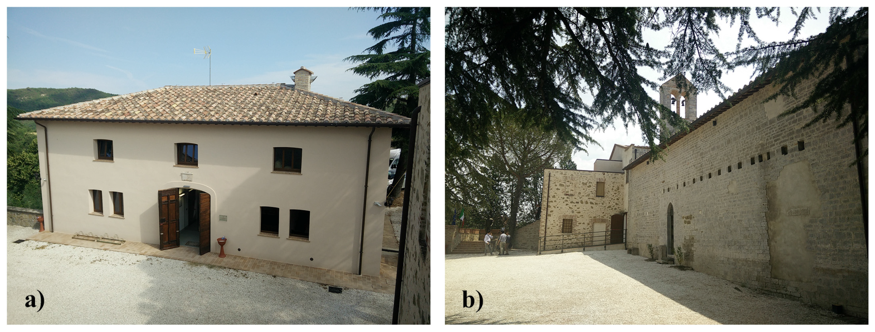
Figure 10.
Scheme of the installed pilot plant.

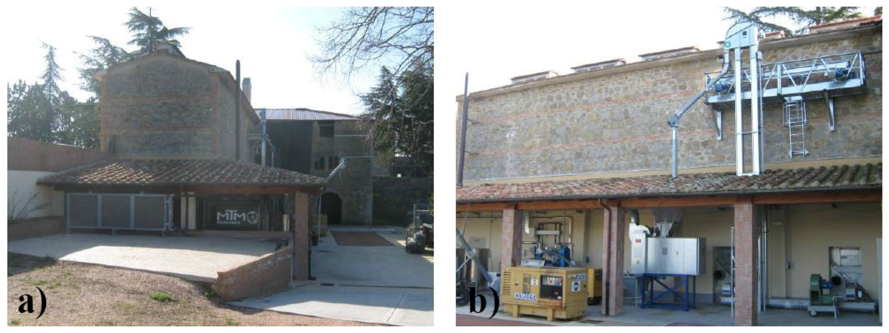
Figure 11.
Side (a) and front (b) view of the installed pilot plant.

Figure 12.
Cogeneration vegetable oil plant (a) and cooling tower (b).

Figure 13.
Front (a) and side (b) view of the bio-gas plant.
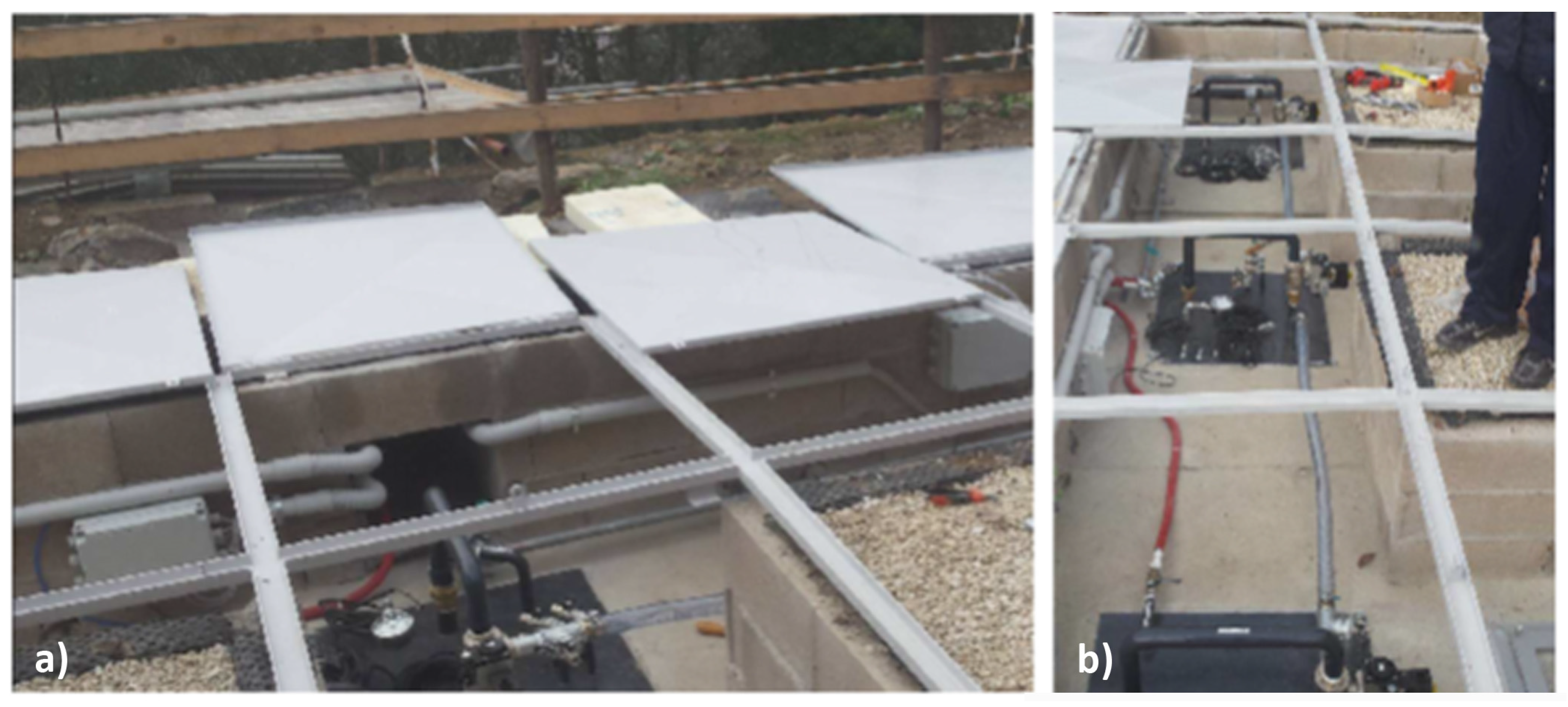
Figure 14.
Management system of the bio-gas plant.


Table 1.
Comparison between the allocation of points and weightings for each topic in LEED® 2009 Italia Nuove Costruzioni e Ristrutturazioni and in GBC Historic Building®.
Table 1.
Comparison between the allocation of points and weightings for each topic in LEED® 2009 Italia Nuove Costruzioni e Ristrutturazioni and in GBC Historic Building®.
| Topic | LEED® NC 2009 Italia | GBC Historic Building® | ||
|---|---|---|---|---|
| Points per Topic | Topic Weightings (%) | Points per Topic | Topic Weightings (%) | |
| Historic Value (HV) | N/A | N/A | 20 | 18.2 |
| Sustainable Sites (SS) | 26 | 23.6 | 13 | 11.8 |
| Water Efficiency (WE) | 10 | 9.1 | 8 | 7.3 |
| Energy and Atmosphere (EA) | 35 | 31.8 | 29 | 26.4 |
| Materials and Resources (MR) | 14 | 12.7 | 14 | 12.7 |
| Indoor Environmental Quality (EQ) | 15 | 13.6 | 16 | 14.5 |
| Innovation (ID) | 6 | 5.5 | 6 | 5.5 |
| Regional Priority (RP) | 4 | 3.6 | 4 | 3.6 |
| Total | 110 | 100% | 110 | 100% |
Table 2.
Characteristics of the building envelope components.
| Retrofitted Building Envelope Components | Layers Materials | Materials Conductivity (W/mK) | Properties |
|---|---|---|---|
| Insulated External walls—ground and 1st floor | - Plaster (0.03 m) | 0.80 | U = 0.33 W/m2K R = 2.97 m2K/W |
| - Lime mortar (0.01 m) | 0.70 | ||
| - Hard stone (0.40 m) | 3.50 | ||
| - Lime sand (0.03 m) | 1.80 | ||
| - Fiber Cork panel (0.08 m) | 0.04 | ||
| - Limestone mortar (0.03 m) | 0.70 | ||
| - Lime mortar (0.03 m) | 0.80 | ||
| Non-insulated external walls—underground floor | - Lime mortar (0.04 m) | 0.70 | U = 2.27 W/m2K R = 0.44 m2K/W |
| - Hard stone (0.74 m) | 3.50 | ||
| Internal partitions | - Lime plaster (0.013 m) | 0.80 | U = 2.03 W/m2K R = 0.49 m2K/W |
| - Brick (0.08 m) | 0.72 | ||
| - Lime plaster (0.013 m) | 0.80 | ||
| Internal load bearing wall—ground and 1st floor | - Lime plaster (0.013 m) | 0.80 | U = 0.83 W/m2K R = 1.19 m2K/W |
| - Brick (0.3 m) | 0.72 | ||
| - Lime plaster (0.013 m) | 0.80 | ||
| Internal load bearing wall—ground and underground floor | - Lime mortar (0.013 m) | 0.70 | U = 2.28 W/m2K R = 0.43 m2K/W |
| - Hard stone (0.40 m) | 3.50 | ||
| - Lime mortar (0.023 m) | 0.70 | ||
| Internal load bearing wall–ground floor | - Lime mortar (0.013 m) | 0.70 | U = 1.69 W/m2K R = 0.59 m2K/W |
| - Cast concrete (0.08 m) | 1.13 | ||
| - Concrete blocks (0.16 m) | 1.04 | ||
| - Cast concrete (0.08 m) | 1.13 | ||
| - Lime mortar (0.013 m) | 0.70 | ||
| Floor—ground and 1st floor | - Ceramic tiles (0.03 m) | 0.85 | U = 0.50 W/m2K R = 4.58 m2K/W |
| - Reinforced concrete (0.09 m) | 1.90 | ||
| - EPS (0.04 m) | 0.04 | ||
| - Concrete slab for underfloor heating (0.06 m) | 0.72 | ||
| - Ceramic tiles (0.03 m) | 0.85 | ||
| Floor—underground floor | - Cement slab (0.10 m) | 0.72 | U = 0.22 W/m2K R = 1.98 m2K/W |
| - Air gap (0.20 m) | - | ||
| - Cast concrete (0.05 m) | 1.13 | ||
| - EPS (0.10 m) | 0.04 | ||
| - Concrete slab (0.05 m) | 0.16 | ||
| - XPS (0.04 m) | 0.034 | ||
| - Concrete slab for underfloor heating (0.06 m) | 0.72 | ||
| - Ceramic tiles (0.03 m) | 0.85 | ||
| Roof | - Fir wood (0.40 m) | 0.14 | U = 0.29 W/m2K R = 3.39 m2K/W |
| - Vapor resistant membrane (0.002 m) | 0.40 | ||
| - Wood fiber (0.14 m) | 0.039 | ||
| - Water resistant membrane (0.002 m) | 0.20 | ||
| - Ceramic tiles (0.7 m) | 0.85 | ||
| Windows | - Low-emissivity double-glass panels (4 mm/15 mm Argon/4 mm) | Solar factor = 0.579 U = 1.317 W/m2K |
Table 3.
Results of the laboratory tests on the roof tiles in different orientations.
| Orientation | Solar Reflectance | Thermal Emittance | Solar Reflection Index |
|---|---|---|---|
| North | 0.32978 | 0.865 | 35 |
| South | 0.32878 | 0.865 | 35 |
| East | 0.32879 | 0.865 | 35 |
| West | 0.32222 | 0.865 | 33 |
Table 4.
Prerequisites and credits achieved by category for the retrofit scenario of the case study building. The table shows prerequisites and credits achieved by the case study only and not all the available ones in the protocol.
Table 4.
Prerequisites and credits achieved by category for the retrofit scenario of the case study building. The table shows prerequisites and credits achieved by the case study only and not all the available ones in the protocol.
| Prerequisites and Credits per Category | Points Available | Points Achieved | |
|---|---|---|---|
| Historic Value (HV) | |||
| Prerequisite 1 | Preliminary analysis | Mandatory | Achieved |
| Credit 2 | Project reversibility | 1–2 | 1 |
| Credit 3.1 | Compatibility of the new use and open community | 1–2 | 1 |
| Credit 4 | Sustainable construction site | 1 | 1 |
| Sustainable Sites (SS) | |||
| Prerequisite1 | Construction activity pollution prevention | Mandatory | Achieved |
| Credit 2.1 | Alternative transportation—public transportation access | 1 | 1 |
| Credit 2.2 | Alternative transportation—bicycle storage and changing rooms | 1 | 1 |
| Credit 2.3 | Alternative transportation—low-emitting and fuel-efficient vehicles | 1 | 1 |
| Credit 2.4 | Alternative transportation—parking capacity | 1 | 1 |
| Credit 4 | Stormwater design: quality and quantity control | 2 | 2 |
| Credit 5 | Heat island effect: non-roof and roof | 2 | 2 |
| Water Efficiency (WE) | |||
| Prerequisite 1 | Water use reduction | Mandatory | Achieved |
| Credit 1 | Water-efficient landscaping | 1–3 | 3 |
| Credit 2 | Water use reduction | 1–3 | 3 |
| Credit 3 | Water metering | 1–2 | 1 |
| Energy and Atmosphere (EA) | |||
| Prerequisite 1 | Fundamental commissioning of building energy systems | Mandatory | Achieved |
| Prerequisite 2 | Minimum energy performance | Mandatory | Achieved |
| Prerequisite 3 | Fundamental refrigerant management | Mandatory | Achieved |
| Credit 1 | Optimize energy performance | 1–17 | 17 |
| Credit 2 | Renewables energies | 1–6 | 6 |
| Credit 3 | Enhanced commissioning | 2 | 2 |
| Credit 4 | Enhanced refrigerant management | 1 | 1 |
| Credit 5 | Measurement and verification | 3 | 3 |
| Materials and Resources (MR) | |||
| Prerequisite 1 | Storage and collection of recyclables | Mandatory | Achieved |
| Prerequisite 2 | Demolition and construction waste management | Mandatory | Achieved |
| Prerequisite 3 | Building reuse | Mandatory | Achieved |
| Credit 2 | Demolition and construction waste management | 1–2 | 2 |
| Credit 3 | Materials reuse | 1–5 | 2 |
| Credit 5 | Regional materials | 1–2 | 1 |
| Indoor Environmental Quality (EQ) | |||
| Prerequisite 1 | Minimum IAQ performance | Mandatory | Achieved |
| Prerequisite 2 | Environmental tobacco smoke (ETS) control | Mandatory | Achieved |
| Credit 1 | Indoor air monitoring | 2 | 2 |
| Credit 2 | Minimum outdoor air delivery assessment | 2 | 2 |
| Credit 3.1 | Construction IAQ management plan—during construction | 1 | 1 |
| Credit 3.2 | Construction IAQ management plan—before occupancy | 1 | 1 |
| Credit 4.1 | Low-emitting materials—adhesives and sealants, cement-based materials and timber finishes | 1 | 1 |
| Credit 4.2 | Low-emitting materials—paints and coatings | 1 | 1 |
| Credit 6.1 | Controllability of systems—lighting | 1 | 1 |
| Credit 6.2 | Controllability of systems—thermal comfort | 1 | 1 |
| Credit 7.1 | Thermal comfort—design | 1 | 1 |
| Credit 7.2 | Thermal comfort—verification | 2 | 2 |
| Innovation (ID) | |||
| Credit 1 | Innovation in design | 1–5 | 4 |
| Credit 2 | GBC Historic Building® Accredited Professional | 1 | 1 |
| Regional Priority (RP) | |||
| Credit 1 | Regional priority | 1–4 | 4 |
| Total points available | Total points achieved | ||
| 110 | 74 | ||
Table 5.
Energy requirement separated by final usage for the baseline building.
| Primary Energy by Use (kWh)—Baseline Building | ||||||||
|---|---|---|---|---|---|---|---|---|
| Months | Electricity | Heating | Cooling | General Lighting | Task Lighting | Exterior Lighting | Equipment | Mechanical Ventilation |
| Jan | 468.04 | 6920.06 | / | 1561.26 | 38.94 | 60.28 | 140.58 | 40 |
| Feb | 426.88 | 5678.81 | / | 1436.04 | 35.4 | 45.17 | 127.8 | 37.31 |
| Mar | 451.28 | 5525.1 | / | 1544.61 | 37.17 | 33.77 | 134.19 | 43.31 |
| Apr | 426.88 | 3143.7 | 19.55 | 1436.04 | 35.4 | 17.39 | 127.8 | 46.9 |
| May | 488.62 | 1421.01 | 152.91 | 1623.87 | 40.71 | 8.31 | 146.97 | 52.51 |
| Jun | 430.7 | 76.83 | 336.56 | 1482 | 35.4 | 3.56 | 127.8 | 51.83 |
| Jul | 488.62 | / | 727.49 | 1623.87 | 40.71 | 4.48 | 146.97 | 52.51 |
| Aug | 470.98 | / | 628.26 | 1607.22 | 38.94 | 13.17 | 140.58 | 52.11 |
| Sep | 448.34 | 44.03 | 332.81 | 1498.65 | 37.17 | 26.7 | 134.19 | 53.33 |
| Oct | 488.62 | 2409.28 | 20.32 | 1623.87 | 40.71 | 45.93 | 146.97 | 50.52 |
| Nov | 450.4 | 4242.53 | / | 1544.61 | 37.17 | 52.05 | 134.19 | 43.59 |
| Dec | 427.76 | 6748.85 | / | 1436.04 | 35.4 | 54.56 | 127.8 | 40.17 |
Table 6.
Energy requirement separated by final usage for the design building.
| Primary Energy by Use (kWh)—Design Building | ||||||||
|---|---|---|---|---|---|---|---|---|
| Months | Electricity | Heating | Cooling | General Lighting | Task Lighting | Exterior Lighting | Equipment | Mechanical Ventilation |
| Jan | 506.36 | 1786.57 | / | 679.68 | 15.00 | 60.23 | 125.24 | 0.56 |
| Feb | 458.59 | 1569.14 | / | 624.11 | 13.80 | 45.11 | 113.86 | 0.58 |
| Mar | 495.18 | 1500.97 | / | 671.61 | 14.85 | 33.42 | 119.55 | 0.61 |
| Apr | 474.32 | / | 14.84 | 616.97 | 13.80 | 17.41 | 113.86 | 0.63 |
| May | 517.80 | / | 451.35 | 698.42 | 15.60 | 8.25 | 130.94 | 0.72 |
| Jun | 475.88 | / | 1193.34 | 637.43 | 14.25 | 3.60 | 113.86 | 0.70 |
| Jul | 516.04 | / | 1900.92 | 695.79 | 15.60 | 4.49 | 130.94 | 0.68 |
| Aug | 507.62 | / | 1640.09 | 688.75 | 15.45 | 13.16 | 125.24 | 0.69 |
| Sep | 486.06 | / | 1169.10 | 647.10 | 14.40 | 26.72 | 119.55 | 0.71 |
| Oct | 516.48 | 689.97 | / | 704.51 | 15.60 | 45.93 | 130.94 | 0.73 |
| Nov | 487.88 | 1079.80 | / | 669.28 | 14.85 | 52.06 | 119.55 | 0.63 |
| Dec | 481.61 | 1544.62 | / | 626.43 | 13.80 | 54.51 | 113.86 | 0.56 |
© 2017 by the authors. Licensee MDPI, Basel, Switzerland. This article is an open access article distributed under the terms and conditions of the Creative Commons Attribution (CC BY) license (http://creativecommons.org/licenses/by/4.0/).
Share and Cite
MDPI and ACS Style
Castaldo, V.L.; Pisello, A.L.; Boarin, P.; Petrozzi, A.; Cotana, F. The Experience of International Sustainability Protocols for Retrofitting Historical Buildings in Italy. Buildings 2017, 7, 52. https://doi.org/10.3390/buildings7020052
AMA Style
Castaldo VL, Pisello AL, Boarin P, Petrozzi A, Cotana F. The Experience of International Sustainability Protocols for Retrofitting Historical Buildings in Italy. Buildings. 2017; 7(2):52. https://doi.org/10.3390/buildings7020052
Chicago/Turabian StyleCastaldo, Veronica Lucia, Anna Laura Pisello, Paola Boarin, Alessandro Petrozzi, and Franco Cotana. 2017. "The Experience of International Sustainability Protocols for Retrofitting Historical Buildings in Italy" Buildings 7, no. 2: 52. https://doi.org/10.3390/buildings7020052
Note that from the first issue of 2016, this journal uses article numbers instead of page numbers. See further details here.