Seismic Reinforcement of a R.C. School Structure with Strength Irregularities throughout External Bracing Walls


1
Department of Civil, Environmental Engineering and Architecture, University of Cagliari, 09123 Cagliari, Italy
2
Department of Energy, Systems, Territory and Construction Engineering, University of Pisa, 56126 Pisa, Italy
*
Author to whom correspondence should be addressed.
Buildings 2017, 7(3), 58; https://doi.org/10.3390/buildings7030058
Submission received: 13 April 2017
/
Revised: 24 June 2017
/
Accepted: 26 June 2017
/
Published: 29 June 2017
(This article belongs to the Special Issue Traditional and Innovative Approaches in Seismic Design)
Abstract
:The effect of irregularities due to the non-uniform distribution of material properties on structural elements of a significant real case is here investigated. Mechanical tests performed on a typical Italian reinforced concrete (r.c.) school building built in the 1960s showed irregularity in the distribution of compression strength in columns, even though the construction is featured by substantially symmetric distribution of the frames. Extreme scenarios in the distribution of irregularities in compression strength of concrete columns are analyzed, with the hypothesis of rigid or deformable slabs. The seismic analysis showed the influence of the response due to the irregular distributions of concrete strength. A proposal of equivalent “material eccentricity” is shown to account for the mentioned irregularity. Furthermore, the practical solution of reinforcement to mitigate the effects of irregularities is also described. It consists of couple of external r.c. walls stiffened by r.c. buttresses added to the building, connected by transverse slabs. An extensive reduction of material eccentricity is achieved, together with a relevant improvement in seismic capacity.
1. Introduction
The role of irregularities in the seismic response of buildings [1] is a critical issue in the evaluation of structural reliability, as observed in recent Italian earthquakes [2,3,4,5,6], mainly in those built during the 1960s.
The irregularities [6,7,8]—similarly to the out-of-plane rocking response [9,10,11,12] and the energy dissipation of existing constructive elements [13,14,15]—are not completely covered by codes such as Eurocode 8 part 3 [16]. Furthermore, the on-site tests play a fundamental role in the knowledge of an existing construction [15] that should be properly regulated. The level of maintenance of a construction is a further aspect that should be taken into account on structural codes, also for extreme climatic events [17]. Finally, the possibility of protecting the building with preventive provisory elements is a relevant issue to be evaluated in the seismic protection of cultural heritage or historic elements [18].
An issue relevant to the seismic assessment of existing buildings is related to the wide dispersion of strength values. During the 1960s, the concrete was extensively produced on-site without quality control methods. This fact induced significant differences in the strength of r.c. elements of the same building. The water/concrete ratio and the handmade compaction phases were primary factors of inhomogeneity [19]. In the present paper, only concrete strength variation is assumed, neglecting the variation of the strength of the steel bars.
A current instrument to account for uncertainty in knowledge of the structural elements is the Confidence Factor [15], although in the current Italian code, it is related only to the number of tests provided on the structure [20]. In the present case, extreme scenarios of strength distribution are performed through non-linear static analysis. It permits the role of inhomogeneity in concrete strength to be emphasized, independently of the number of experimental tests. [6]. No differences are considered in the height distribution of mechanical properties. The results are compared considering both rigid and flexible slabs. Referring to the irregularities induced by the non-uniform distribution of strength [21] of vertical elements in r.c. structures [8], a possible helpful strategy for designers should be based in terms of “material eccentricity”. The concept of eccentricity is currently used to determine the well-known center of mass and of stiffness of a building. The definition of “center of strength” as the center of the horizontal forces of collapse acting on the columns, together with its eccentricity, can then be easily implemented in numerical codes [6].
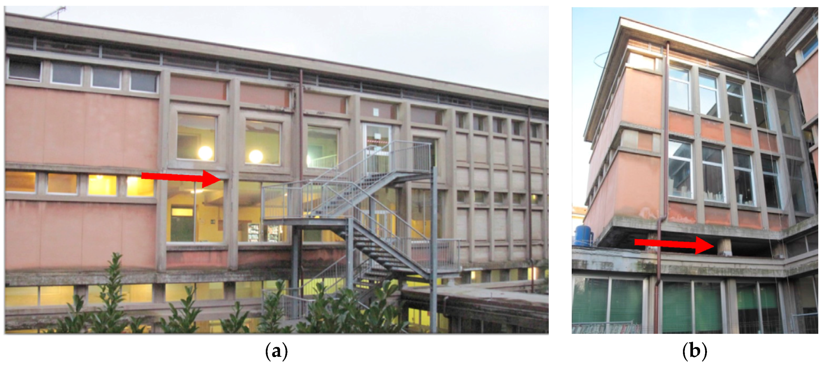
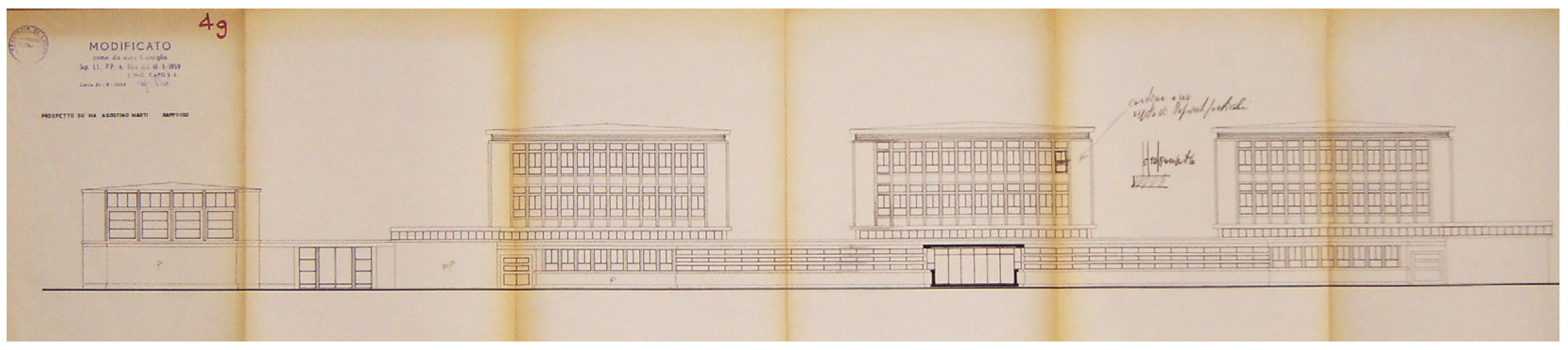
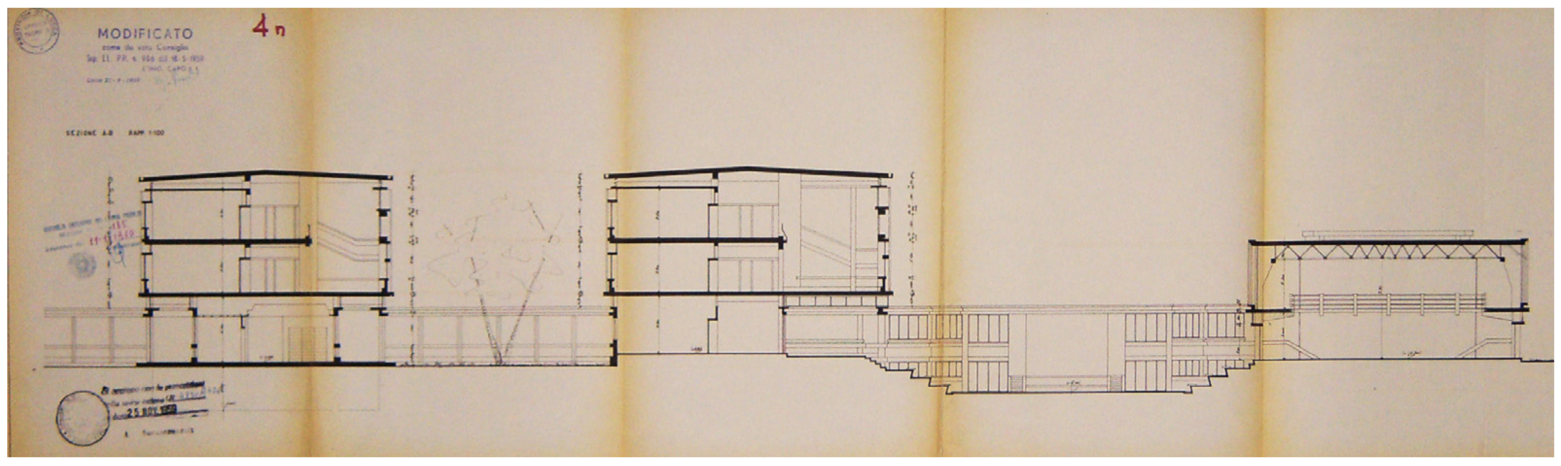
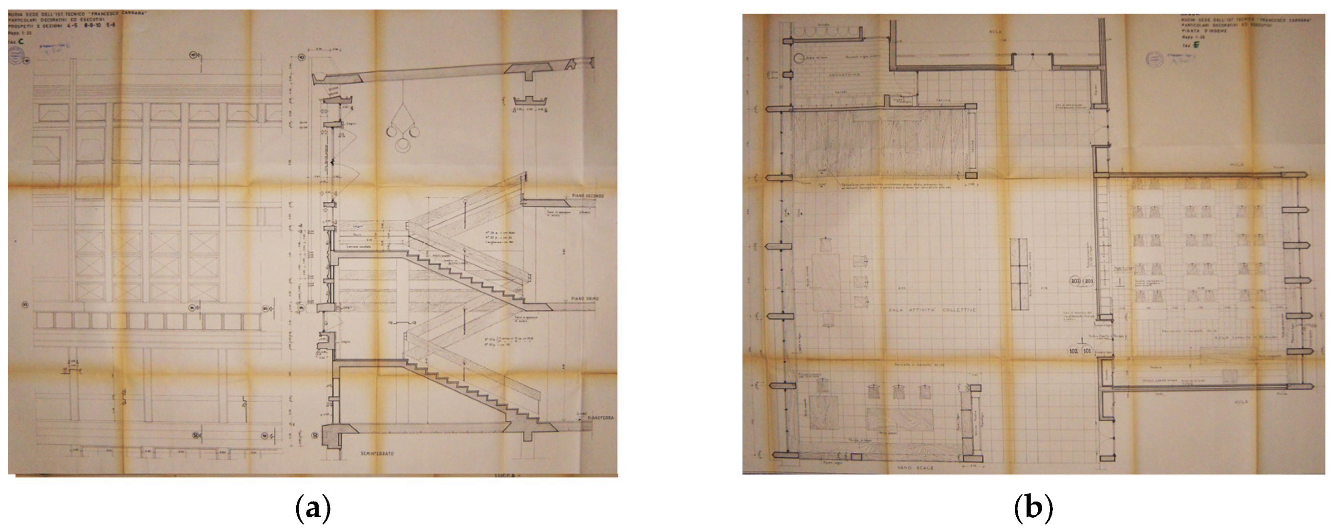
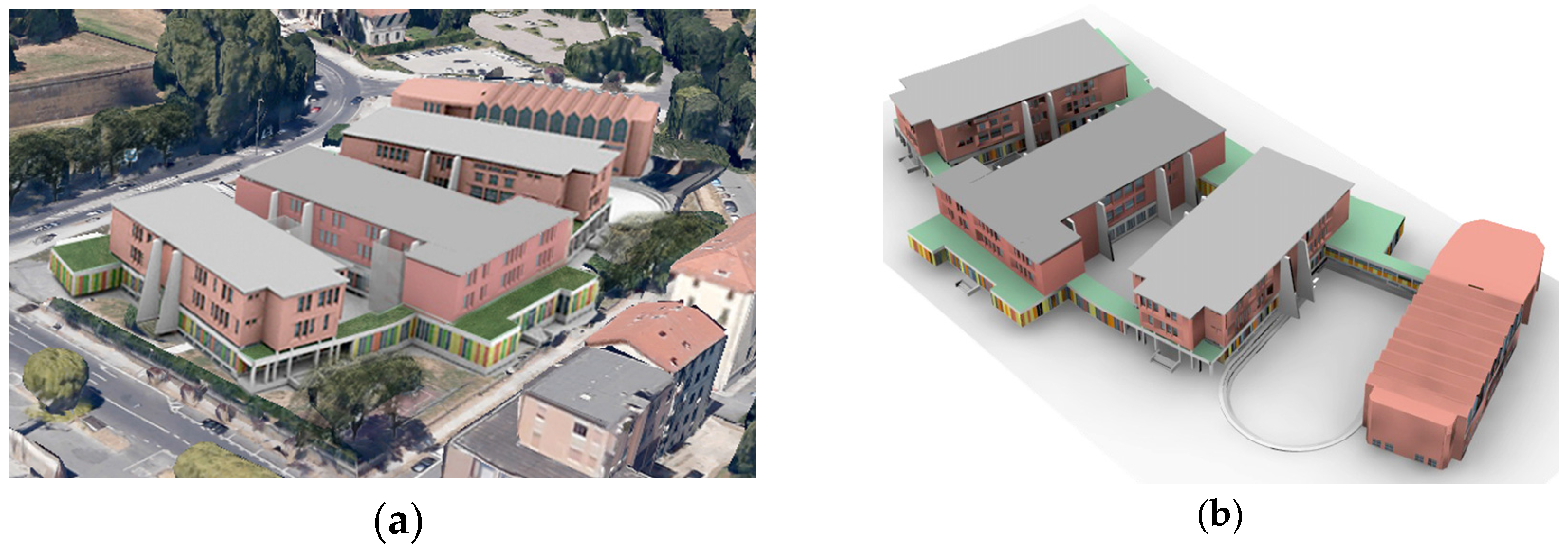
An example based on an existing r.c. building is illustrated. The school building “I.T.C. Carrara” is a complex from the early 1960s, located in Lucca (Italy) (Figure 1, Figure 2 and Figure 3). It consists of four isolated buildings labeled A, B, C, and D, weakly joined to a one-floor structure. The pavilion B (Figure 2) is formed by three levels and a basement on an extension of about 1000 m2/level. A large number of thin r.c. columns, together with a set of short columns at the top of the ground floor (Figure 3) are seismically vulnerable. Original drawings are available (Figure 4, Figure 5 and Figure 6). Poor quality of the concrete is another relevant and emblematic aspect of seismic vulnerability of the building. In this sense, the considered example represents a typical situation of r.c. constructions that must be urgently enforced.
The requirements of economy and short time for intervention (to minimize the interruption of school service), together with conservation of most of the interior parts, forced towards a solution of external r.c. walls. This choice was also induced by the need to reduce the structural effects due to material irregularity of concrete columns.
2. Analysis before Intervention
A typical feature of concrete constructions built in the 1960s and 1970s is the relevant scattering of the concrete compression strength, caused by the reduced level of automation which in that period allowed columns to be put in place with low productivity levels (only a few columns per day). The in-situ production of concrete was then influenced by environmental and episodic or local conditions (Figure 7). A numerical study was carried out on the strength variability of concrete columns, with the aim of evaluating the sensitivity to this phenomenon. In the absence of more accurate assessments, mechanical experiments on concrete columns were performed through 12 cylindrical cores and 60 Schmidt Hammer tests (each of 15 rebound measurements) from the adjacent pavilion, available for experiments. A mean compression strength of 24.8 MPa was determined, with a standard deviation of 9.6 MPa. A conventional upper strength of 34.4 MPa and a lower of 15.2 MPa have then been assumed. The Confidence Factor of the structure was determined according to EC8, by the analysis of geometry, details, and materials of the structure. Geometry was defined starting from original drawings (examples in Figure 4, Figure 5 and Figure 6), verified by a full structural survey (Figure 8). A satisfactory knowledge of beams and column size was allowed with the help of the calculation report of the time of construction. A set of 20 different column and beam sections was found. One-way r.c. slabs showed 160 or 200 mm thickness without concrete slab. Structural details such as steel bar configurations were obtained by simulating design, joined with a partial availability of original drawings, according to codes and constructive practice of the 1960s. The mechanical characterization of the steel bars was referred to data from [22], verifying it with technical indications on the original calculation report. A yielding strength of 3699 MPa was then assumed. Finally, due to the in situ tests, a Confidence Factor of 1.20 was applied to mechanical proprieties (Table 1) as by Italian code [20].
The model of the B pavilion was implemented with the code SAP2000 v.17.0 (CSI, New York, NY, USA). Only main structural elements were modelled (columns and beams) as elastic mono-dimensional elements (frame), taking into account their actual stiffness and resistance. The model did not consider the node failure. Node failure is affected by variability of the strength of both the concrete and the steel [22], but in the adopted model the non-linearity was assumed to be only caused by the mechanical behavior of columns, neglecting the role of the beam–column nodes. Secondary structural elements such as perimeter and internal non-loadbearing walls were represented in term of mass. Gravity loads acting on slabs were transferred to beams by shell elements by means of influence areas. The foundation was not modelled, with full restrained joints at the base neglecting any structure–foundation interaction.
Two different schemes were analyzed: the first one with rigid floor diaphragm and the second one with in-plane flexible floors by means of equivalent thickness membrane. In both models, the mean values of material proprieties were initially implemented. Classic modal analysis was firstly performed to evaluate the modal frequencies and the mass participant ratios (Table 2).
A non-linear static analysis was then performed for both models under gravity and monotonically increasing horizontal loads. According to EC8 and Italian NTC 2008, two load distributions were used: one proportional to the modal shape, and the other proportional to the masses. Participant mass of the first mode for the Y direction was lower than 75%, so the modal distribution has been taken as proportional to the force distribution of a response spectrum analysis.
In the case of rigid floors, seismic forces were applied at the centre of mass of each storey. In the case of flexible floor, seismic forces were distributed through “areas of influence” and unidirectional slabs. Seismic masses were uniformly distributed on the supports of the beams. The non-linearity in frames [23] was defined by considering a lumped plasticity model by means of plastic hinges assigned at the extremities of each column [24]. In SAP2000 plastic hinges, properties can be defined depending on the type of hinge, and thus on the type of load–deformation relationship (moment–rotation), and depending on available form, as forms for only axial, shear, torsion, and moment or for interacting hinges (P-M2, P-M3, M2-M3, and P-M2-M3). The main force–deformation relation for r.c. elements, suggested by FEMA 356, were already implemented; limit values depended on the non-linear behaviour of each structural type and were indicated by FEMA itself or by laboratory tests. The different strength of the two groups of columns also affect the stiffness according to the relation [20]:
From the capacity curve obtained by push-over analysis (Figure 9), the frames appeared sensible to the floor flexibility, particularly along the Y direction.
The evaluation of the displacements was performed by referring to the N2-method [25] by comparing seismic demand to capacity. A set of numerical analysis occurred for both rigid and flexible slabs. The structural checks were performed with two types of analyses:
- (i)
- Evaluation of shear behavior (brittle mechanism).
- (ii)
- Evaluation of compression-bending behavior (ductile mechanism).
As expected, the brittle mechanisms were more dangerous than the ductile ones, taking place for lower displacements (Figure 10). More in detail, the collapse of the structure started with a shear failure of the squat columns along the building perimeter between first and second floor, followed by a shear failure of the ground floor columns.
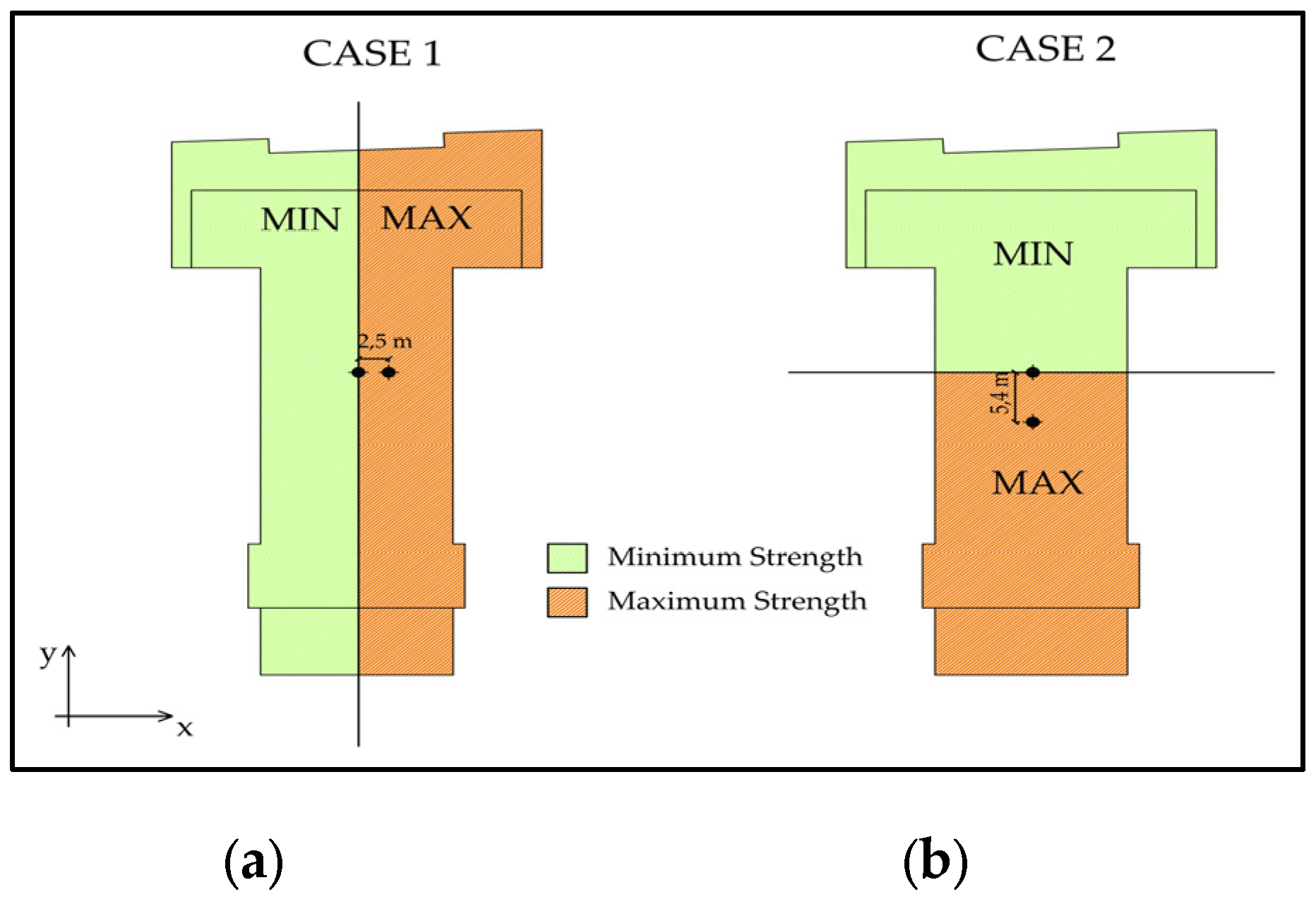
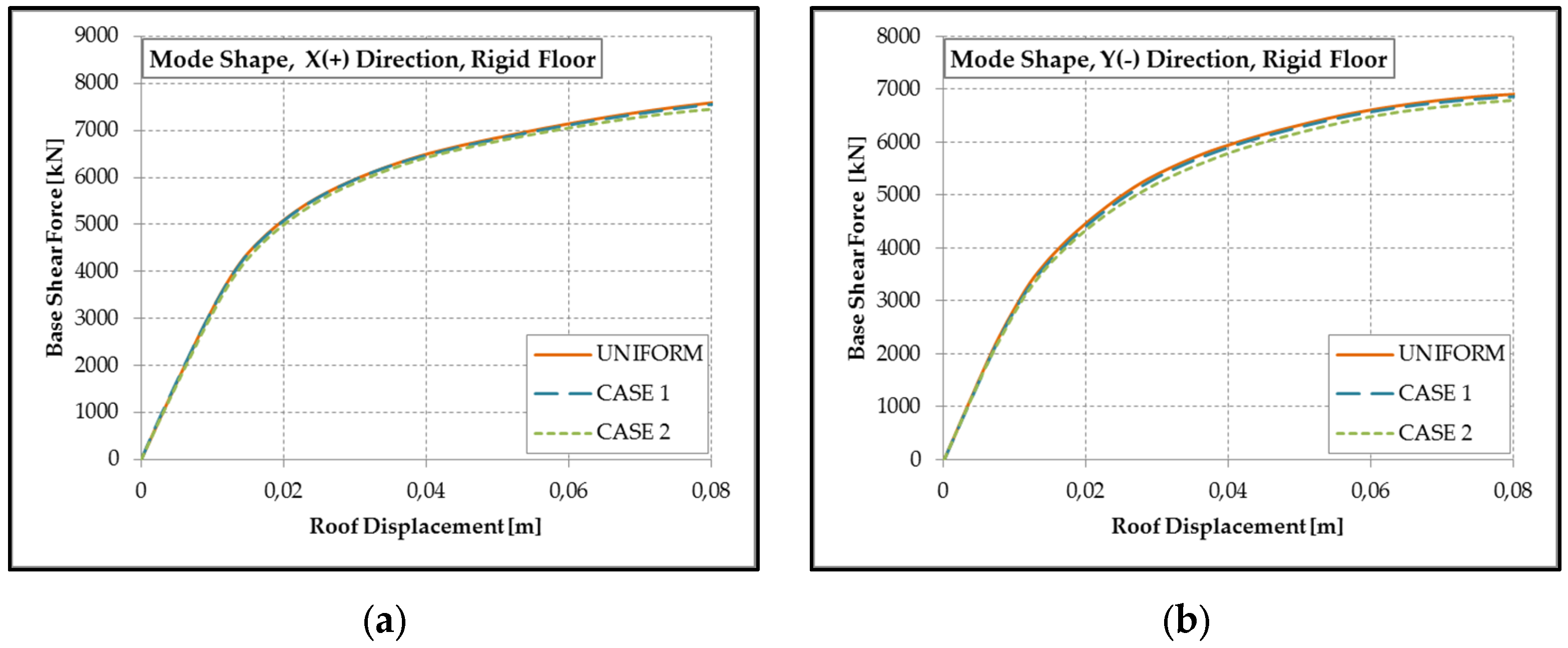
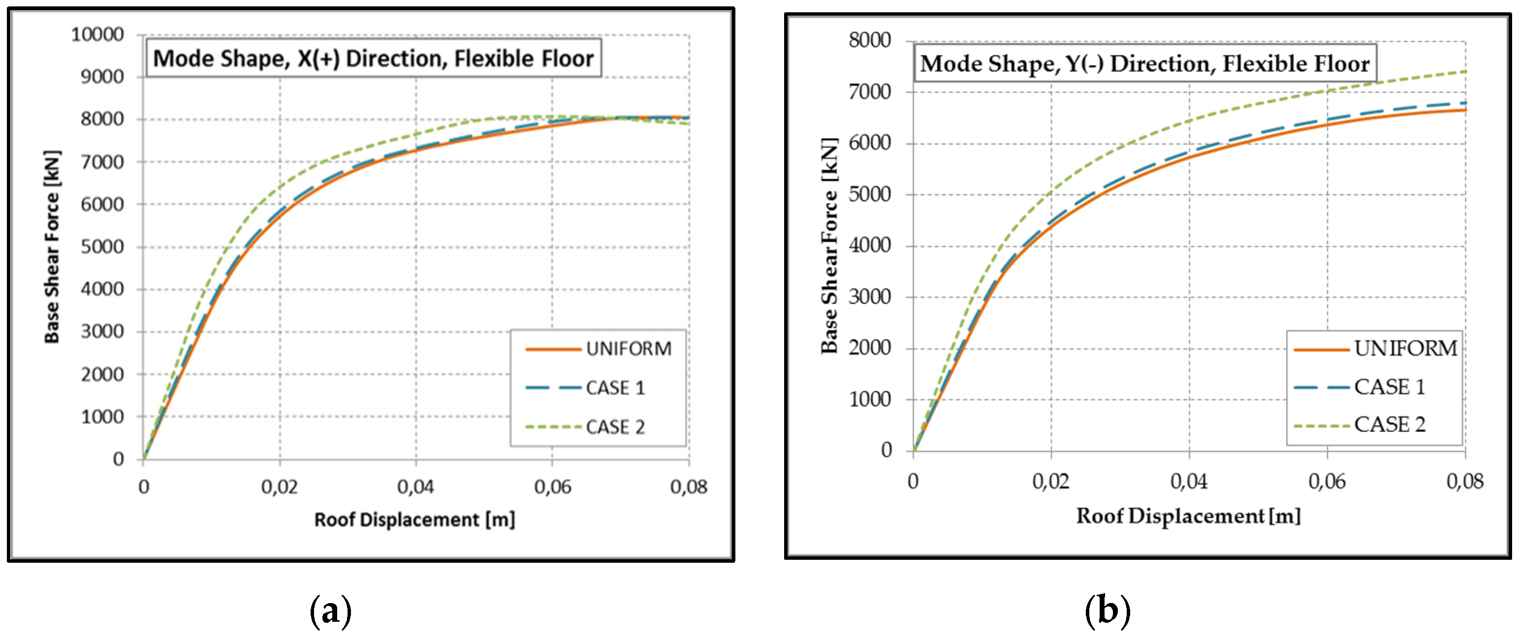
Values of maximum and minimum concrete compression strength, as defined before, were assigned to the structural elements (beams and columns) with two extreme distributions in plan (Figure 11), considering both models (rigid and flexible slabs). The capacity curves—given by push-over analysis in both X and Y directions—showed the structure as more sensitive to the variation of the concrete strength in the model with flexible floors—particularly in the Y direction (Figure 12 and Figure 13). The mode shape distributions of the equivalent seismic transverse loads systematically furnished a more severe result with respect to the uniformly shaped ones. To compare the different cases, the compression-bending strength of the ground floor pillars was chosen as collapse mechanism.
3. Results of analysis
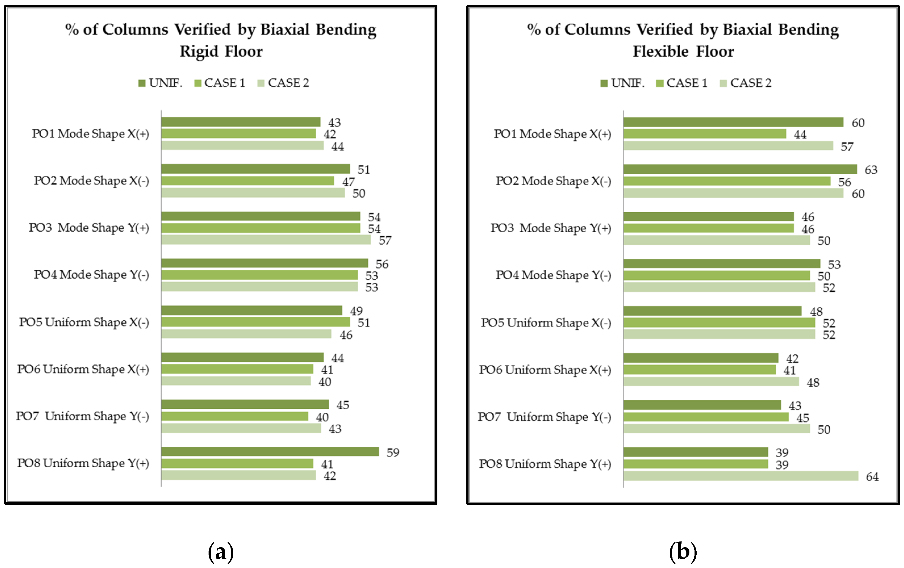
The assumption of rigid slab has made unessential any material asymmetry assumed (Figure 12). It can be noticed that in this case, the displacement of the control point is related to the average value of the assigned concrete strength. The average concrete strength does not differ significantly from the average value assumed for uniform distribution assumed in non-linear static analysis. The capacity curves of Figure 12 are emblematic in this sense. On the contrary, in the model with flexible slabs (Figure 13) sensible differences occurred, mainly for irregular distributions along the Y direction. It was also testified by the higher number of columns allowing the failure limit, compared with the uniform distribution of strength, as in the histograms of Figure 14.
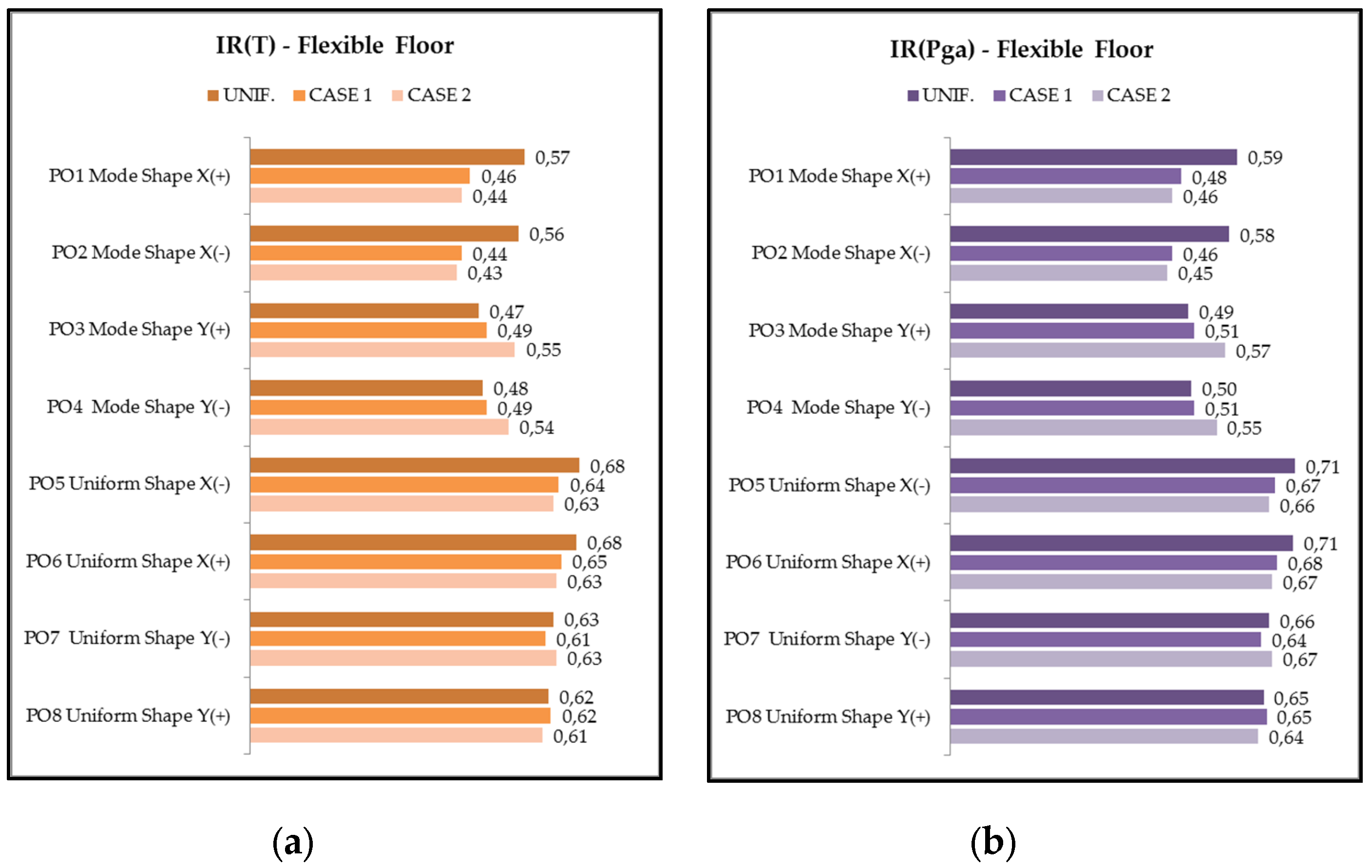
The results obtained show the role of the rigid slabs in mitigating the effect of irregularity in horizontal force strength of the r.c. columns. Conversely, a flexible slab is more sensible to the variation of stiffness of the elements produced by the variation of the mechanical properties. This does not necessarily mean a worsening in the global behavior of the structure, as evidenced by Case 2. Finally, the Index of Seismic Risk (IR) of the unreinforced state was estimated, with the following formulas:
where PGAC refers more specifically to the acceleration to the bedrock that determines severe damage and therefore a loss of structural resistance; PGAD is the acceleration value with the probability of exceeding 10% in 50 years (return period 712 years);
where TRC is the return period of the structure before intervention, and TRD is the return period associated at the ultimate limit state (712 years).
Its variation has been analyzed modifying the slab type (rigid or flexible) and the distribution of the concrete strength (Case 1 and Case 2), depending on both the peak ground acceleration (PGA) and the reference return period (TR) of the earthquake.
The values of IR (Figure 15) confirmed the sensitivity of the structure to the variation in distribution of the material, with lower risk for Case 1 and higher risk for Case 2, with respect to uniform distribution of the concrete strength.
4. Seismic Retrofitting
The pavilions in this study are under seismic reinforcement. The images provided are of the A pavilion. The intervention consists of the insertion of couple of symmetrical opposed r.c. bracing walls, stiffened by transverse r.c. buttresses, able to absorb the majority (more than 85%) of the design seismic action. Their positions correspond to the inner stairs and the toilets, with the aim of minimizing the impact on classrooms. These bracing systems are appropriately connected to the building: each portion of slab between the opposed walls is demolished and reconstructed through new r.c. plates well connected to walls. The r.c. bracing walls are also supported by a series of micropiles (Figure 16 and Figure 17). The bracings are calculated to absorb the entire amount of the design seismic actions (Figure 18), achieving after retrofitting an index of seismic risk (IR) greater than one. The r.c. walls are also able to perform a stiffness more than ten times the global stiffness of the existing r.c. frames. The quality and uniformity of the concrete used on the new r.c. walls are strongly controlled. In this sense, the effect of material irregularity is then neglected. The geometrical disposition of the bracing system is based on centering of the center of strength, decreasing the eccentricity due to the dispersion of the concrete strength. The architectural effect of the refurbishment is in Figure 19, where the r.c. bracing walls are also aesthetically harmonized with the new façades.
5. Discussion and conclusions
The paper deals with the concept of center of strength and its “material eccentricity” on r.c. framed structures, in order to highlight its influence on the seismic response. It was performed through pushover analyses applied to a real case of r.c. building located in Italy. Two limit scenarios were considered, in order to emphasize the in-plan location of the center of strength. In the case of rigid slabs, the differences resulted less relevant, whereas if the floors were flexible, much greater differences emerged, in terms of global capacity curve, single elements verifications, and local generalized displacements. Concerning global capacity curves, the most important differences with the uniform case were found in the strength distribution orthogonal to the axis of symmetry of the building. The analysis showed how the structure was influenced by variability of the concrete compression strength. Comparison of the extreme distribution with the reference model with uniform distribution was performed both at global level (comparison between push-over curves) and at local level. The maximum differences (about 25%) of columns with respect to the failure limit have been observed in case of flexible slabs. Seismic risk index varied from 0.45 to 0.71. Thus, the “material eccentricity” can be assumed as a geometric factor, in addition to the accidental eccentricity.
Those values obtained neglecting the role of beams and nodes made necessary a structural intervention [26] to increase the strength of the structure. The illustrated strategy of reinforcement was based on additional r.c. shear walls, forced to move the majority of seismic actions from columns to the new walls, joined with a relevant reduction of the eccentric of the center of strength. Further studies should be addressed to evaluate their mechanical behavior in the case of blast loads as in [27] to appreciate the role of external r.c. walls as a practical strategy for the reinforcement of existing r.c. framed structures, together with more effective monitoring strategies for concrete [28].
Acknowledgments
The activity was financed by the District of Lucca with a contract to the University of Pisa on seismic monitoring of public schools.
Author Contributions
M.S. conceived the intervention and the design strategy. M.L.P. managed the engineering structural retrofit of the school complex and improved the structural details. E.M. and M.L.P. performed the numerical analysis. All the authors contributed in the same way to prepare the paper.
Conflicts of Interest
The authors declare no conflict of interest.
References
- De Stefano, M.; Pintucchi, B. A review of research on seismic behaviour of irregular building structures since 2002. Bull. Earthq. Eng. 2008, 285–308. [Google Scholar] [CrossRef]
- Andreini, M.; De Falco, A.; Giresini, L.; Sassu, M. Structural damage in the cities of Reggiolo and Carpi after the earthquake on May 2012 in Emilia Romagna. Bull. Earthq. Eng. 2014. [Google Scholar] [CrossRef]
- Rovero, L.; Alecci, V.; Mechelli, J.; Tonietti, U.; De Stefano, M. Masonry walls with irregular texture of L’Aquila (Italy) seismic area: Validation of a method for the evaluation of masonry quality. Mater. Struct. 2016, 49, 2297–2314. [Google Scholar] [CrossRef]
- Augenti, N.; Parisi, F. Learning from Construction Failures due to the 2009 L’Aquila, Italy, Earthquake. J. Perform. Constr. Facil. 2010, 24, 536–555. [Google Scholar] [CrossRef]
- De-la-Colina, J.; Gonzalez-Perez, C.A.; Valdes-Gonzalez, J. Accidental eccentricities, frame shear forces and ductility demands of buildings with uncertainties of stiffness and live load. Eng. Struct. 2016, 124, 113–127. [Google Scholar] [CrossRef]
- Basu, D.; Giri, S. Accidental eccentricity in multistory buildings due to torsional ground motion. Bull. Earthq. Eng. 2015, 13, 3779–3808. [Google Scholar] [CrossRef]
- Parisi, F.; Augenti, N. Seismic capacity of irregular unreinforced masonry walls with openings. Earthq. Eng. Struct. Dyn. 2013, 42, 101–121. [Google Scholar] [CrossRef]
- De Stefano, M.; Tanganelli, M.; Viti, S. Variability in concrete mechanical properties as a source of in-plan irregularity for existing RC framed structures. Eng. Struct. 2014, 59, 161–172. [Google Scholar] [CrossRef]
- Giresini, L.; Sassu, M. Horizontally restrained rocking blocks: Evaluation of the role of boundary conditions with static and dynamic approaches. Bull. Earthq. Eng. 2017, 15, 385–410. [Google Scholar] [CrossRef]
- Giresini, L.; Fragiacomo, M.; Sassu, M. Rocking analysis of masonry walls interacting with roofs. Eng. Struct. 2016, 116, 107–120. [Google Scholar] [CrossRef]
- Giresini, L.; Fragiacomo, M.; Lourenço, P.B. Comparison between rocking analysis and kinematic analysis for the dynamic out-of-plane behavior of masonry walls. Earthq. Eng. Struct. Dyn. 2015, 44, 2359–2376. [Google Scholar] [CrossRef]
- Sassu, M. The Reinforced Cut Wall (RCW): A Low-Cost Base Dissipator for Masonry Buildings. Earthq. Spectra 2006, 22, 533–554. [Google Scholar] [CrossRef]
- Sassu, M. Biaxiality effect on the energy dissipated by elastoplastic base-isolators. J. Eng. Mech. 2003, 129, 607–612. [Google Scholar] [CrossRef]
- Giresini, L. Energy-based method for identifying vulnerable macro-elements in historic masonry churches. Bull. Earthq. Eng. 2016, 14, 919–942. [Google Scholar] [CrossRef]
- Andreini, M.; De Falco, A.; Giresini, L.; Sassu, M. Mechanical characterization of masonry walls with chaotic texture: Procedures and results of in-situ tests. Int. J. Archit. Herit. Conserv. Anal. Restor. 2014, 8, 376–407. [Google Scholar] [CrossRef]
- EC8–3 Eurocode 8: Design of Structures for Earthquake Resistance—Part 3: Assessment and Retrofitting of Buildings 2005. Available online: http://eurocodes.jrc.ec.europa.eu/home.php (accessed on 13 April 2017).
- Andreini, M.; De Falco, A.; Giresini, L.; Sassu, M. Collapse of the historic city walls of Pistoia (Italy): Causes and possible interventions. Appl. Mech. Mater. 2013, 352, 1389–1392. [Google Scholar] [CrossRef]
- De Falco, A.; Giresini, L.; Sassu, M. Temporary preventive seismic reinforcements on historic churches: Numerical modeling of San Frediano in Pisa. Appl. Mech. Mater. 2013, 352, 1393–1396. [Google Scholar] [CrossRef]
- Hurst, L. Historic Concrete: Background to Appraisal; Thomas Telford: London, UK, 2001; pp. 45–67. [Google Scholar]
- CMIT Circolare del Ministro delle Infrastrutture e dei Trasporti 2 febbraio 2009, n. 617, contenente le Istruzioni per l’applicazione delle “Nuove norme tecniche per le costruzioni” di cui al DM 14 gennaio 2008. Suppl. Ord. 2009. (Italian). Available online: www.cslp.it/cslp/index.php (accessed on 13 April 2017).
- Myslimaj, B.; Tso, W.K. Desirable strength distribution for asymmetric structures with strength-stiffness dependent elements. J. Earthq. Eng. 2004, 8, 231–248. [Google Scholar] [CrossRef]
- Casapulla, C.; Jossa, P.; Maione, A. Rocking motion of a masonry rigid block under seismic actions: A new strategy based on the progressive correction of the resonance response|Il moto sotto sisma del blocco murario: Analisi per progressiva correzione della risposta in risonanza. Ing. Sismica 2010, 27, 35–48. [Google Scholar]
- Carta, G.; Stochino, F. Theoretical models to predict the flexural failure of reinforced concrete beams under blast loads. Eng. Struct. 2013, 306–315. [Google Scholar] [CrossRef]
- De Luca, F.; Verderame, G.M. A practice-oriented approach for the assessment of brittle failures in existing RC elements. Eng. Struct. 2013, 48, 373–388. [Google Scholar] [CrossRef]
- Fajfar, P. A Nonlinear Analysis Method for Performance-Based Seismic Design. Earthq. Spectra 2000, 16, 573–592. [Google Scholar] [CrossRef]
- De Luca, F.; Verderame, G.M.; Manfredi, G. Eurocode-based seismic assessment of modern heritage RC structures: The case of the Tower of the Nations in Naples (Italy). Eng. Struct. 2014, 74, 96–110. [Google Scholar] [CrossRef]
- Stochino, F. RC beams under blast load: Reliability and sensitivity analysis. Eng. Fail. Anal. 2016, 66, 544–565. [Google Scholar] [CrossRef]
- Mistretta, F.; Piras, M.V.; Fadda, M.L. A reliable visual inspection method for the assessment of r.c. structures through fuzzy logic analysis, Life-Cycle of Structural Systems: Design, Assessment, Maintenance and Management. In Proceedings of the 4th International Symposium on Life-Cycle Civil Engineering IALCCE 2014, Tokoy, Japan, 16–19 November 2014; pp. 1154–1160. [Google Scholar]
Figure 1.
Plan (a) and aerial view (b) of the School Complex I.T.C. F. Carrara (Lucca–Italy).
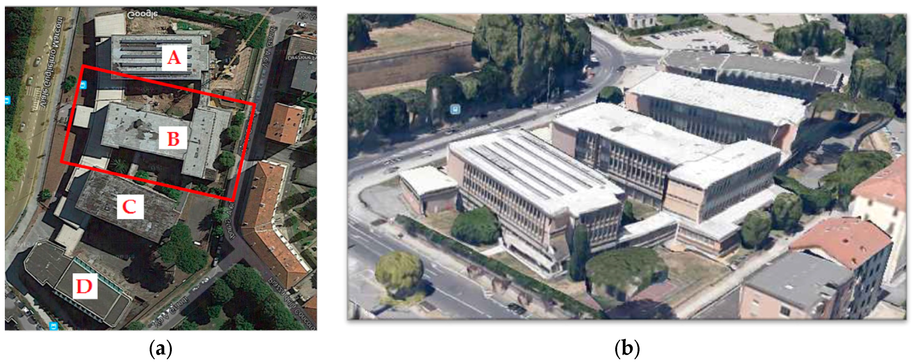
Figure 2.
View of the B pavilion (right) and C pavilion (left).

Figure 3.
Details of seismic vulnerability: (a) slender columns close to a double height spacing; (b) squat element (brittle shear force) in r.c. columns.
Figure 3.
Details of seismic vulnerability: (a) slender columns close to a double height spacing; (b) squat element (brittle shear force) in r.c. columns.

Figure 4.
Original drawing of the complex—Frontal view.

Figure 5.
Original drawing of the complex: vertical section.

Figure 6.
Original drawing of the B pavilion: (a) vertical section; (b) plan view.

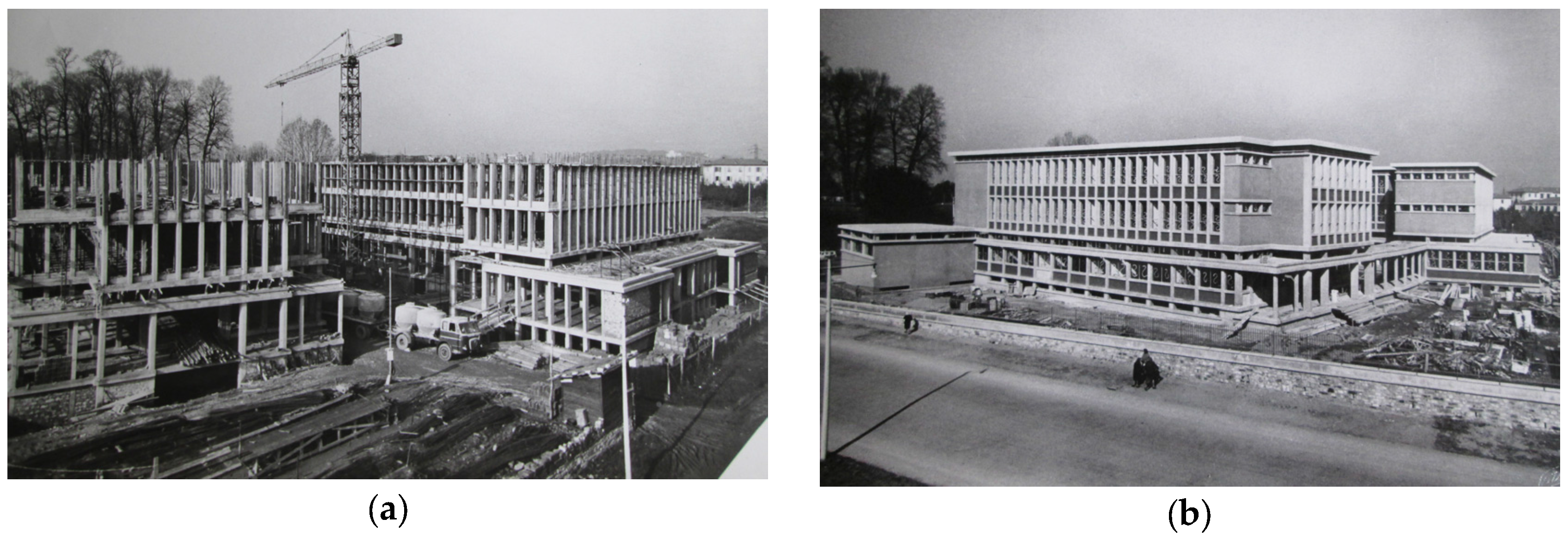
Figure 7.
Historical images of the complex during construction.

Figure 8.
Ground floorplan of the complex.
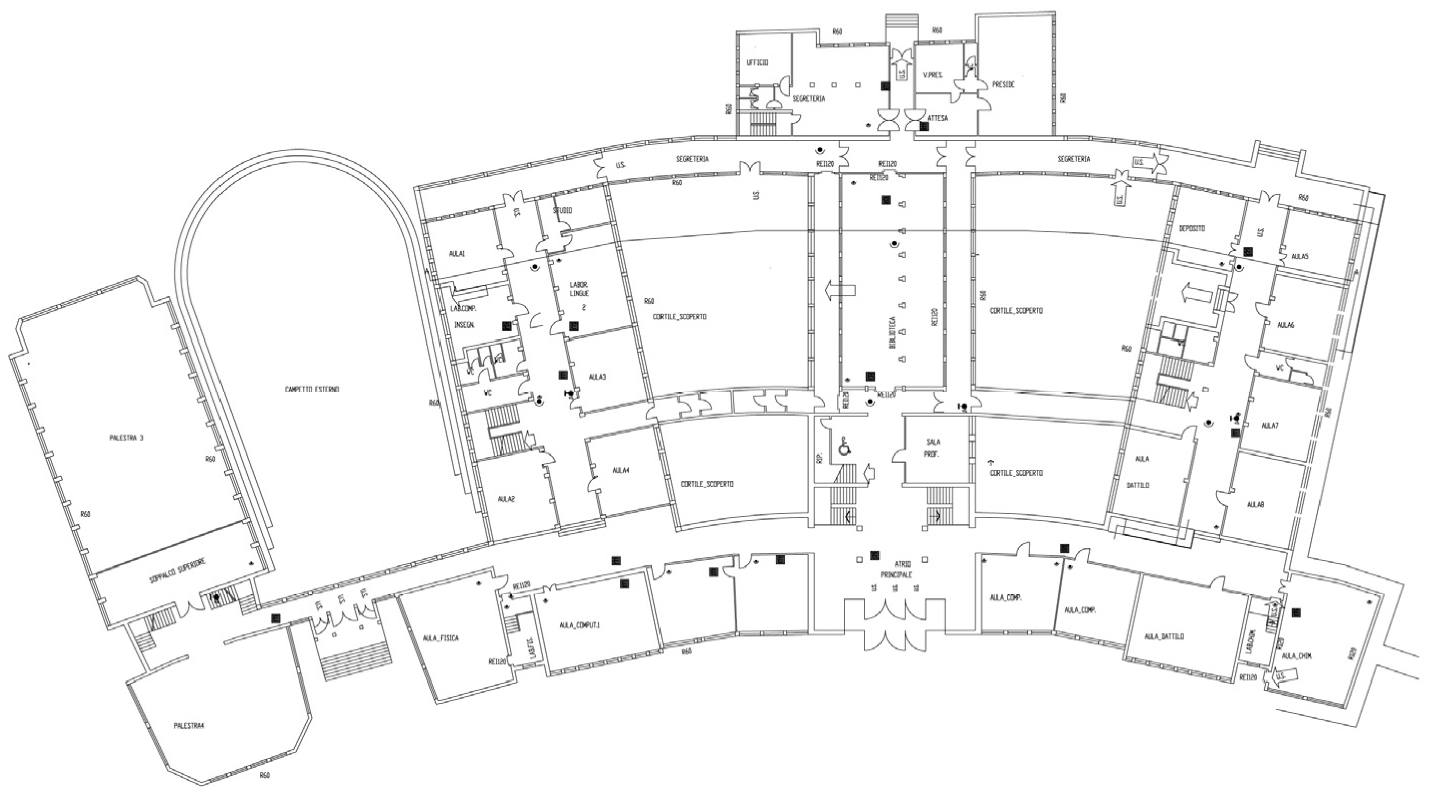
Figure 9.
Pushover capacity curves in X (a) and Y (b) direction, with “uniform” pattern load distribution.
Figure 9.
Pushover capacity curves in X (a) and Y (b) direction, with “uniform” pattern load distribution.

Figure 10.
Capacity curve X direction from “modal” pattern of load distribution—rigid slab.
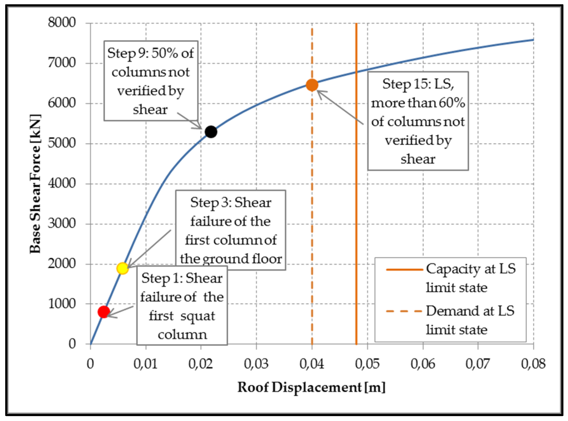
Figure 11.
Extreme distributions of material irregularity: (a) CASE 1 (X direction); (b) CASE 2 (Y direction).
Figure 11.
Extreme distributions of material irregularity: (a) CASE 1 (X direction); (b) CASE 2 (Y direction).

Figure 12.
Capacity curves: (a)X direction; (b) Y direction with “mode shape” load—rigid floor.

Figure 13.
Capacity curves: (a) X direction; (b) Y direction with “mode shape” load—flexible floor.

Figure 14.
Biaxial bending with axial force verification for (a) rigid floor; (b) flexible floor.

Figure 15.
Seismic risks index for (a) reference return period and (b) peak ground acceleration (PGA).
Figure 15.
Seismic risks index for (a) reference return period and (b) peak ground acceleration (PGA).

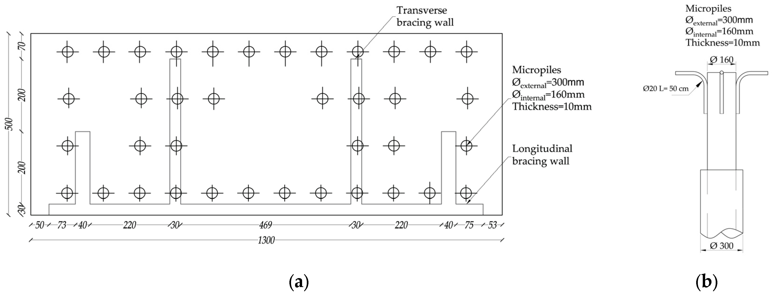
Figure 16.
(a) Micropiles position; (b) Micropile detail.

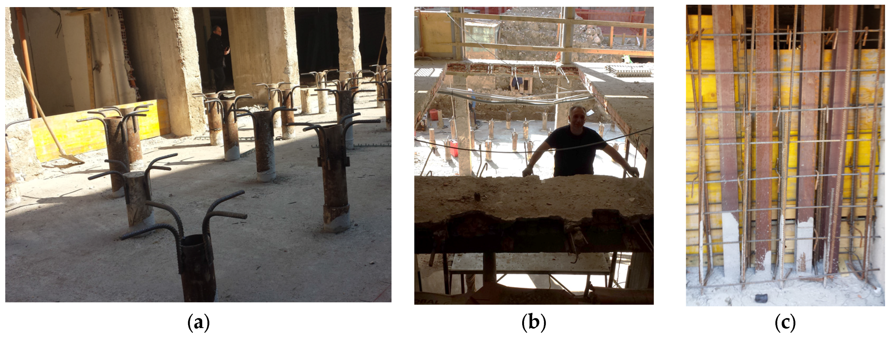
Figure 17.
Phases of the intervention in A pavilion: (a) Micropiles anchoring, before casting of the concrete foundation; (b) Demolition of the slab to ensure the connectivity of the opposing bracing walls; (c) Insertion of the steel reinforcing with profiles HEB100.
Figure 17.
Phases of the intervention in A pavilion: (a) Micropiles anchoring, before casting of the concrete foundation; (b) Demolition of the slab to ensure the connectivity of the opposing bracing walls; (c) Insertion of the steel reinforcing with profiles HEB100.

Figure 18.
(a) Longitudinal r.c. bracing wall; (b) Transverse r.c. bracing wall.
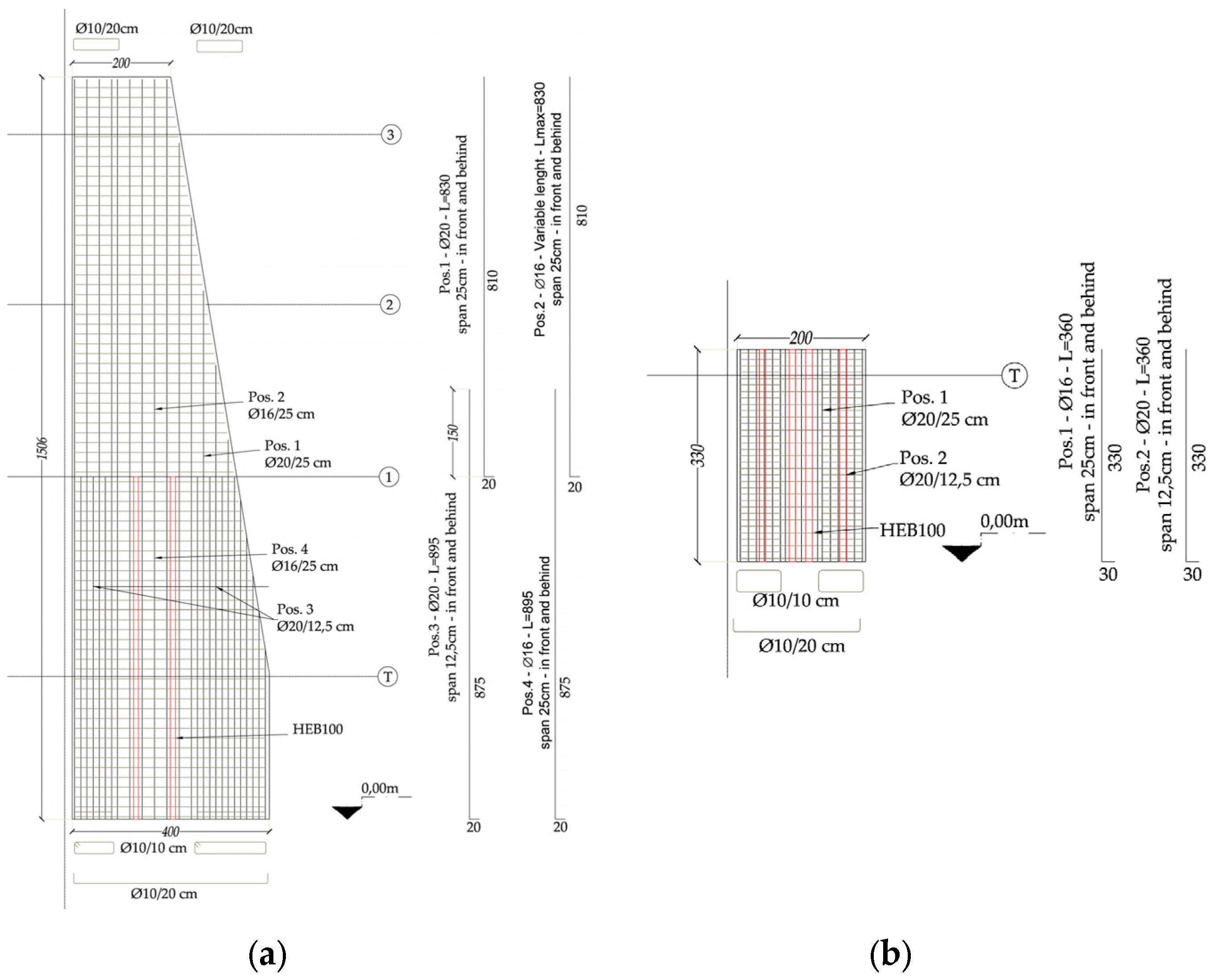
Figure 19.
Rendering views of the school from (a) south-east; (b) north-west.


Table 1.
Mechanical characteristics of the reference model.
| Material | fc (MPa) | Ec (MPa) | fy (MPa) |
|---|---|---|---|
| Concrete | 248 | 28,904 | - |
| Steel | - | - | 3699 |
Table 2.
Modal properties: rigid floor and flexible floor model.
| Model | Mode | T (s) | Mx | My |
|---|---|---|---|---|
| Rigid floor | 1 | 0.450 | 0.78 | - |
| 2 | 0.445 | - | 0.63 | |
| Flexible floor | 1 | 0.494 | - | 0.70 |
| 2 | 0.445 | 0.37 | 0.77 |
© 2017 by the authors. Licensee MDPI, Basel, Switzerland. This article is an open access article distributed under the terms and conditions of the Creative Commons Attribution (CC BY) license (http://creativecommons.org/licenses/by/4.0/).
Share and Cite
MDPI and ACS Style
Sassu, M.; Puppio, M.L.; Mannari, E. Seismic Reinforcement of a R.C. School Structure with Strength Irregularities throughout External Bracing Walls. Buildings 2017, 7, 58. https://doi.org/10.3390/buildings7030058
AMA Style
Sassu M, Puppio ML, Mannari E. Seismic Reinforcement of a R.C. School Structure with Strength Irregularities throughout External Bracing Walls. Buildings. 2017; 7(3):58. https://doi.org/10.3390/buildings7030058
Chicago/Turabian StyleSassu, Mauro, Mario Lucio Puppio, and Eleonora Mannari. 2017. "Seismic Reinforcement of a R.C. School Structure with Strength Irregularities throughout External Bracing Walls" Buildings 7, no. 3: 58. https://doi.org/10.3390/buildings7030058
Note that from the first issue of 2016, this journal uses article numbers instead of page numbers. See further details here.