Analysis of Cylindrical Granular Material Silos under Seismic Excitation


1
SDA-Engineering GmbH, Kaiserstraße 100, TPH III/B, 52134 Herzogenrath, Germany
2
CH-Ingenieure GbR, Charlottenburger Allee 41, 52078 Aachen, Germany
*
Author to whom correspondence should be addressed.
Buildings 2017, 7(3), 61; https://doi.org/10.3390/buildings7030061
Submission received: 27 March 2017
/
Revised: 28 June 2017
/
Accepted: 2 July 2017
/
Published: 6 July 2017
(This article belongs to the Special Issue Traditional and Innovative Approaches in Seismic Design)
Abstract
:Silos generally work as storage structures between supply and demand for various goods, and their structural safety has long been of interest to the civil engineering profession. This is especially true for dynamically loaded silos, e.g., in case of seismic excitation. Particularly thin-walled cylindrical silos are highly vulnerable to seismic induced pressures, which can cause critical buckling phenomena of the silo shell. The analysis of silos can be carried out in two different ways. In the first, the seismic loading is modeled through statically equivalent loads acting on the shell. Alternatively, a time history analysis might be carried out, in which nonlinear phenomena due to the filling as well as the interaction between the shell and the granular material are taken into account. The paper presents a comparison of these approaches. The model used for the nonlinear time history analysis considers the granular material by means of the intergranular strain approach for hypoplasticity theory. The interaction effects between the granular material and the shell is represented by contact elements. Additionally, soil–structure interaction effects are taken into account.
1. Introduction
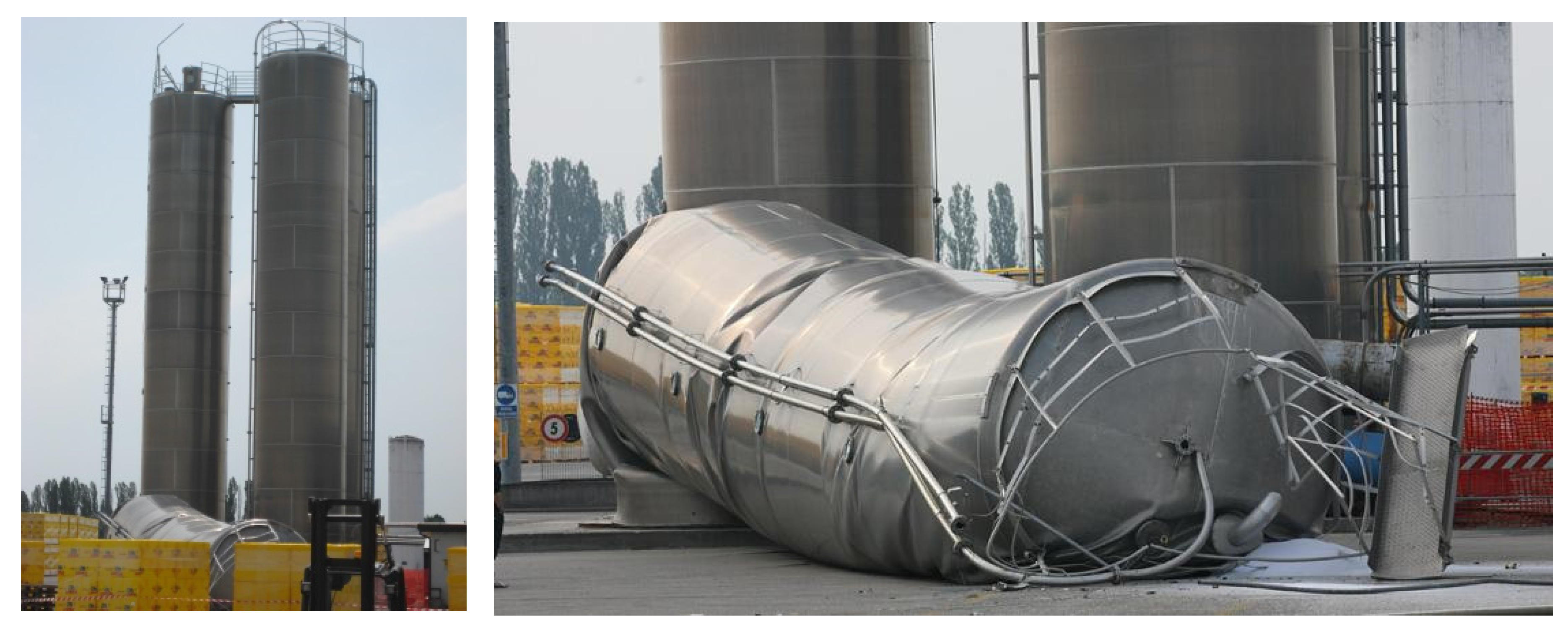
Adequate seismic design of silos is especially important in the field of plant engineering since structural damage often leads to consequential damage such as fires, explosions, and the release of toxic substances into the air and soil. Furthermore, silos are important supply structures that serve to store foodstuffs and industrial goods and to compensate for fluctuations between production and consumption. However, past earthquakes have repeatedly caused damage to silos. One of the main causes for damage is buckling on the foot of the wall of the silo as a result of a combination of axial compressive stresses, circumferential tensile stresses and high shear stresses that is also referred to as “elephant’s foot buckling” and typically related to steel silos. For silos made of reinforced concrete different failure modes may occur [1,2,3]. In addition, slender silos are at risk of tipping over due to high seismic inertial forces when the anchoring or the foundation fails. Silos with substructures are especially at risk of tipping over due to the weight of the silo, which causes the structure to be top-heavy. Figure 1 shows the collapse of a slender silo made of steel as a result of a series of earthquakes in the Emilia–Romagna region in Northern Italy in 2012. In addition to the collapsed silo, the other three silos in the group also exhibited clearly visible buckling damage in the highly stressed areas.
Seismically excited silo structures have long been the subject of intensive research, which has always been the goal of understanding the interaction between filling and silo wall and to derive comprehensible calculation and design concepts. Rotter and Hall [1] investigated the problem of compact cylindrical silos, identified the main failure modes, and derived design criteria for steel silos based on a numerical model. Yokota et al. [4], Shimamato et al. [5], and Sakai et al. [6] carried out vibration tests on cylindrical model silos filled with coal, and derived basic knowledge about the vibration behavior of silos. Younan and Veletsos [7] developed an analytical formulation for describing the seismic response of material-filled silos with rigid walls for constant accelerations, harmonic excitations, and stochastic seismic effects, which were also extended to flexible tank shells [8]. Bauer [9] and Braun [10] dealt with the material behavior of bulk materials and their behavior under dynamic loads. The current version of the Eurocode 8, Part 4 [11], is essentially based on the formulation of Younan and Veletsos [7] and the work of Rotter and Hall [1]. The complex interaction between the filling material and the silo shell is not explicitly taken into account, among other things, by the pressure conditions as well as the soil and wall friction coefficients. Holler and Meskouris [12] showed that the loading rates are too conservative in the case of compact silos, whereas loads on slender silos are well represented. Recent shaking table tests [13] have shown that the approaches in Eurocode 8 [11] are too conservative and the dynamic response is strongly dependent on the wall friction coefficient. Better agreement with the experimental results is obtained with the analytical approach according to Silvestri et al. [14]. The same results are obtained by Pieraccini et al. [15] with an improved approach based on the theory of Silvestri [14].
In the following, firstly the design by means of a non-linear calculation model for cylindrical silos with granular bulk materials is presented taking into account the non-linearities of the bulk material and the interaction of the bulk material with the silo wall. After that, the static load approach of Eurocode 8, Part 4 [11], is applied to a slender silo. A comparison of the two calculation approaches as well as the approach of Silvestri [14] for a squat silo then follows.
2. Equivalent Load Method
The static replacement loads for silo structures must be determined both for the components due to seismic excitation in the horizontal as well as in the vertical direction. The vertical component is not negligible as is often the case in building construction, since the acceleration of the high concentrated silo masses leads to dynamic stress pressures, which are particularly relevant for the design of the hopper outlet.
2.1. Equivalent Seismic Loads in Horizontal Direction
Due to seismic excitation silo walls are subjected to additional horizontal seismic actions caused by the acceleration of the mass of the granular material. These actions can be represented according to Eurocode 8, Part 4 [11], through an additional normal pressure on the wall, which for cylindrical silos is given by
The resulting pressure distribution is shown in Figure 2. Herein Δph,so is the reference pressure acting on the silo wall at a distance x from the flat bottom or from the tip of a conical or pyramidal hopper:
The reference pressure Δph,so depends on the following material and geometrical parameter:
| response acceleration of the silo at a depth from the equivalent surface of the fill mass in g; | |
| characteristic value for the specific weight of the fill mass; | |
| ; | |
| total height of the silo from a flat floor or a hopper tip to the equivalent surface of the fill mass; | |
| interior diameter in cylindrical silos; | |
| angle relative to the direction of the seismic excitation (); | |
| slope of the hopper wall relative to a vertical axis or maximum wall slope (relative to the vertical) for pyramidal hoppers. |
Generally, combinations of the seismic pressure with those resulting from filling or emptying the silo must be considered in order to ensure that no negative (pointing to the interior) pressures arise and the contact between the fill mass and the silo wall is maintained at all times. When such pressure situations occur in higher sections, the negative pressure is redistributed to the opposed pressure-loaded wall of the silo. The acceleration of the silo is described by a variable distribution according to a function , for which the variation of the acceleration along the height must be determined beforehand. If the latter is not known, may be substituted by the value of the acceleration acting at the height of the mass center. Figure 3 shows the pressure distributions due to seismic actions and filling and their superposition for a constant and variable acceleration over the silo height. The static load distributions are reduced at the bottom to take into account that for squat silos a large part of the lateral seismic force is taken up by internal friction in the fill mass and does not affect the silo wall. However, it has to keep in mind, that the simplified distributions are just approximations of the real dynamic pressures.
2.2. Equivalent Seismic Loads in Vertical Direction
Eurocode 8, Part 4 [11], stipulates that vertical seismic loads must be considered in addition to the lateral seismic loads but does not prescribe how to apply them to the silo walls. A meaningful approach consists in deriving the additional dynamic forces directly from the static forces due to filling. To that effect a scaling factor is determined as the spectral acceleration for the fundamental vertical vibration mode, given in units of g. Measurements and numerical results have shown that the fundamental vertical vibration mode is located in the low-period range of the response spectrum, so that the plateau spectral acceleration value can be assumed to be on the safe side. The scaling factor is given by
is then used for computing additional friction pressures for walls and vertical pressures for silo floors and hoppers according to Eurocode 1, Part 4 [16], by simply scaling the pressures due to filling. However, it should also be mentioned that additional seismically induced forces may be computed for the loads arising during silo emptying—which load combination is the most unfavorable must be decided on a case-by-case basis. The importance of vertical seismic pressures increases with higher seismic loads, since the additional pressures are no longer covered by the safety factors for the serviceability limit states. The need to take into account vertical seismic effects is also shown by Silvestri et al. [14]. Here, a comparable load approach to increase the vertical and horizontal wall pressures is proposed.
2.3. Combination of Equivalent Seismic Loads in Horizontal and Vertical Directions
Generally, lateral (in two mutually orthogonal directions) and vertical seismic loads applied to silos must be considered to act jointly. This effect may be taken into account approximately through the standard 30% rule according to Eurocode 8, Part 1 [17]. On the other hand, Eurocode 8, Part 4 [11], stipulates that, for axisymmetric silos, it is sufficient to consider a single lateral component together with the vertical component. Therefore, it is sufficient to consider in total two load combinations.
3. Nonlinear Numerical Simulation Model
The hypoplastic material law is used to describe the behavior of the granular material. Different formulations for hypoplasticity have been investigated: the hypoplasticity based on the formulation of Gudehus [18], two modified versions using time history functions according to Bauer [9] and Braun [10] and the intergranular strain approach developed by Niemunis and Herle [19]. Comparisons of the different approaches with soil mechanic cyclic tests clarifies that the intergranular strain approach according to Niemunis and Herle [19] leads to the most realistic results [12,20]. Therefore, this approach was applied within the overall model.
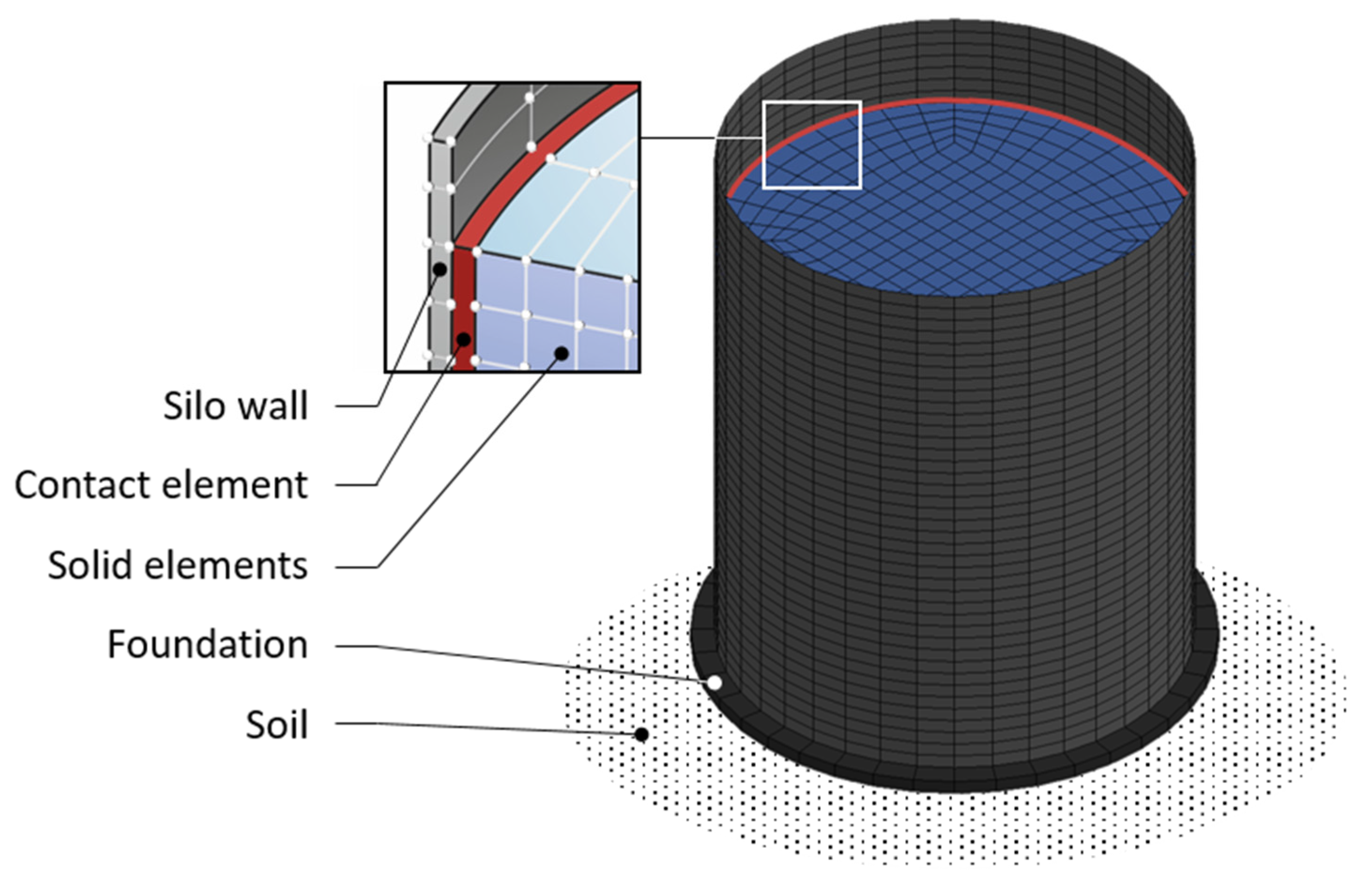
The set-up of the nonlinear simulation model is presented in Figure 4. The foundation slab is placed on the soil, which is regarded as an elastic half space represented by the well-known cone model according to Wolf [21]. The granular material is modeled by 20-node solid elements incorporating the intergranular strain approach according to Niemunis and Herle [19]. The silo wall is represented by eight node shell elements and connected with contact elements to the granular material. The contact elements transfer compression and friction forces and allow for a separation between the filling and the silo wall. The proposed model was validated by shaking table tests of scaled steel silo models [12].
4. Calculation Examples
The design approach of Eurocode 8, Part 4 [11], bases on equivalent static loads representing additional inertial forces due to the acceleration of the material. This assumption leads, in the case of slender silos, to a sufficient correspondence with the actual load-bearing behavior. In the case of squat silos, the internal friction of the granular material near the ground and its load bearing behavior is taken into account only by a short linear increase in the lower region of the silo shell. For this reason, this approach is to be assessed more precisely by a comparison with the non-linear simulation model. For the slender silo, the influence of the use of a constant and variable acceleration profile over the silo height is investigated. The geometry and material parameters for the slender and squat silo are summarized in Table 1.
4.1. Slender Silo
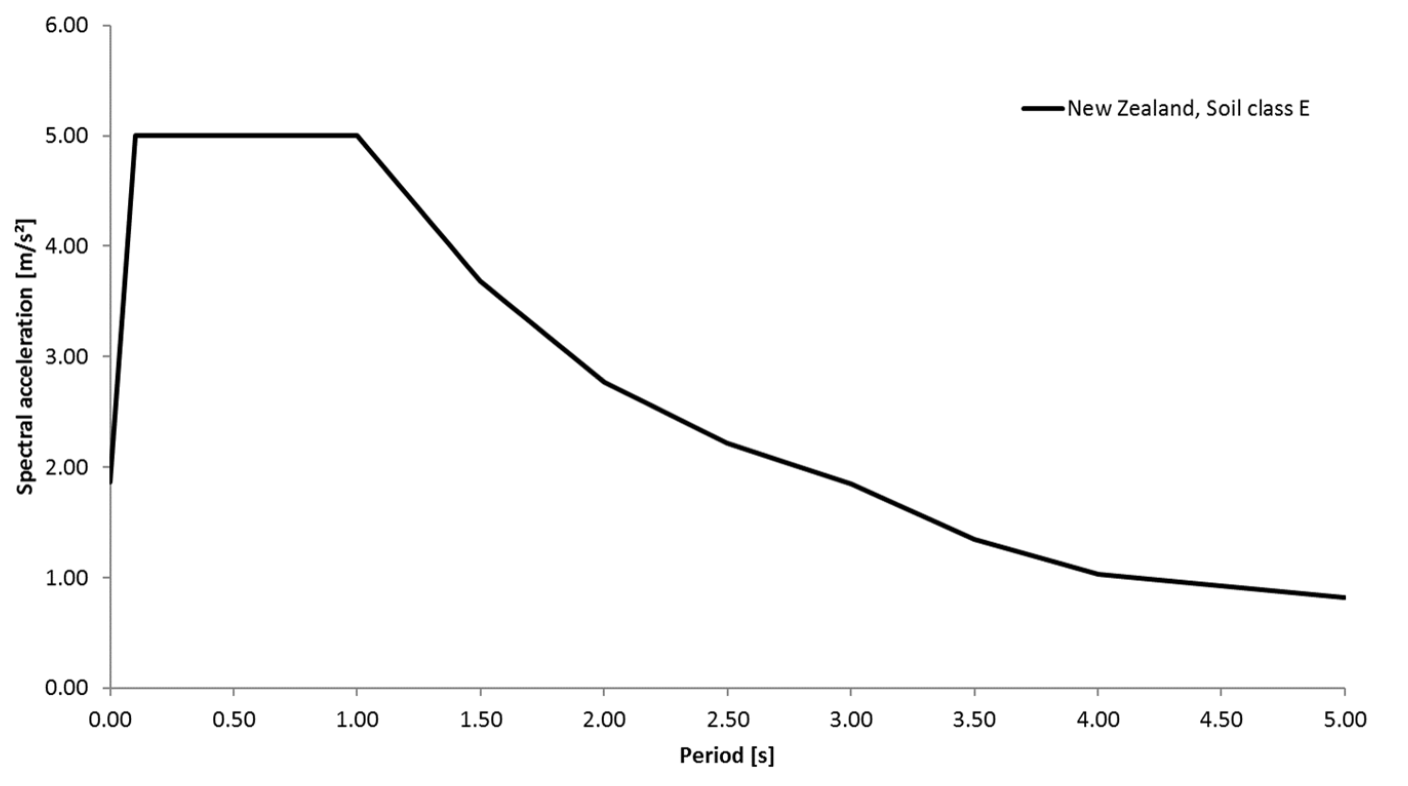
According to Table 1, the slender silo has a height of 30 m, an inner diameter of 6 m, and a constant wall thickness of 8 mm. To determine the acceleration profiles, the silo is simulated as a beam model with 15 lumped masses. These masses consider the dead weight of the silo shell and the granular material (Figure 5). The first eigenfrequency is determined for the multiple mass oscillator at 1.0 Hz. A spectral acceleration of 5 m/s2 is assigned for a location in New Zealand in accordance with the spectrum [22] set in Figure 6, if the ascending branch in the response spectrum is neglected.
With the spectral acceleration of 5 m/s2 and the total mass of 1756.26 t, the base shear is Fb = 8781.3 kN. From this, the linear acceleration profile is determined by the height- and mass-proportional distribution of the forces on the heights of the masses. In addition, the multiple mass oscillator is used to perform a calculation using the multimodal response spectra method, taking into account 10 eigenforms. The course of the accelerations from the multimodal calculation in comparison to the linear approach is shown in Figure 7.
The horizontal seismic pressures acting on the silo wall are calculated according to Section 2.1 using the variable acceleration profiles (Figure 7). They are applied as static equivalent loads together with the static pressures on a finite element model of shell elements. In addition, the seismic loads due to vertical seismic excitation with av = 0.7ah = 3.5 m/s2 according to Section 2.2 are taken into account in the model. Figure 8 shows the resulting circumferential and axial stresses for a constant acceleration as well as for the acceleration profiles given in Figure 7.
To the regarded silo construction, the results show that the linear approach provides the greatest axial stresses, whereas the constant and multimodal approach results in comparable stresses. This is due to the higher accelerations and the more unfavorable distribution of the horizontal forces over the height. The results of the different approaches also vary over the height in the case of the circumferential stresses, although the differences are not as great as for the axial stresses.
4.2. Squat Silo
According to Table 1, the regarded squat silo () has a height of 10 m, an inner diameter of 10 m and a constant wall thickness of 8 mm. The connection to the foundation is assumed to be rigid. A simplified model of the foundation as a rigid reinforced concrete block with a density of 25 kN/m3 is used. The connection to the lower edge of the foundation is represented by a stiffness matrix that models the elastic half space under the foundation for a shear wave velocity of 500 m/s based on the truncated cone model of Wolf [21]. The associated mass fractions and damping ratios are also taken into account in the model.
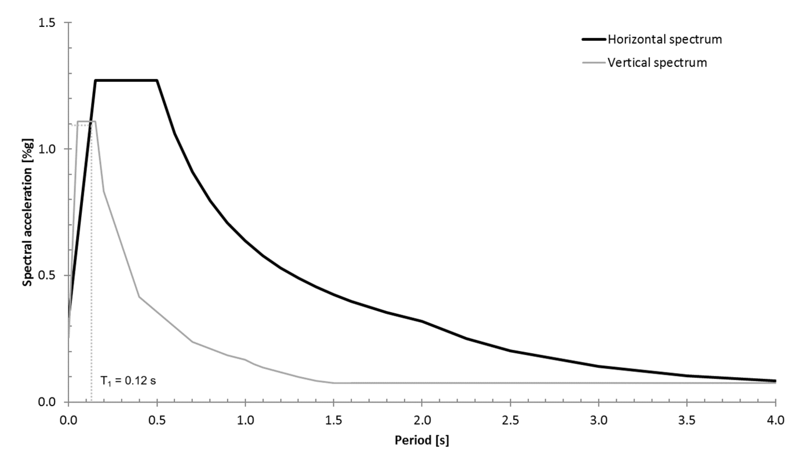
The silo is located in Istanbul, for which a reference peak ground acceleration ag of 4.16 m/s2 must be assumed. The corresponding elastic response spectra in the horizontal and vertical direction according to Eurocode 8, Part 1 [17], for Spectrum Type I and Soil Class B is shown in Figure 9.
Due to the thin walls of the silo and the associated risk of the shell buckling, a behavior factor will not be used (q = 1.0). A linear-elastic continuum model will be used to determine the first Eigen period. The bulk material is idealized using volume elements, and the silo shell is idealized using shell elements. The contact area between the bulk material and the wall of the silo is assumed to be rigid. This model yields a first Eigen period of T1 = 0.12 s taking the interaction between the soil and the structure into account. This results in spectral accelerations of Sah = 10.9 m/s2 in the horizontal direction and Sav = 11.0 m/s2 in the vertical direction. The vertical acceleration results in a scaling factor of = 1.12 according to Equation (4). Due to the stockiness of the silo, the horizontal spectral acceleration is assumed to act on the center of mass and is considered to be constant along the height of the silo as an approximation. Using the approaches for the static equivalent loads of Section 2.1 and Section 2.2, the circumferential and axial stresses presented in Figure 10 and Figure 11 are obtained as a result of the horizontal and vertical effects of the earthquake. Figure 11 additionally shows the comparison of the resulting meridian and ring stresses using the load approach according to Silvestri et al. [14] at a constant spectral acceleration Sav = 11.0 m/s2. It becomes clear here that the approach of Silvestri is more conservative with equal input values. This is because in the proposed approach, the pressure is scaled exponentially according to the theory of Jansen [23] while that of [14] suggests a linear approach.
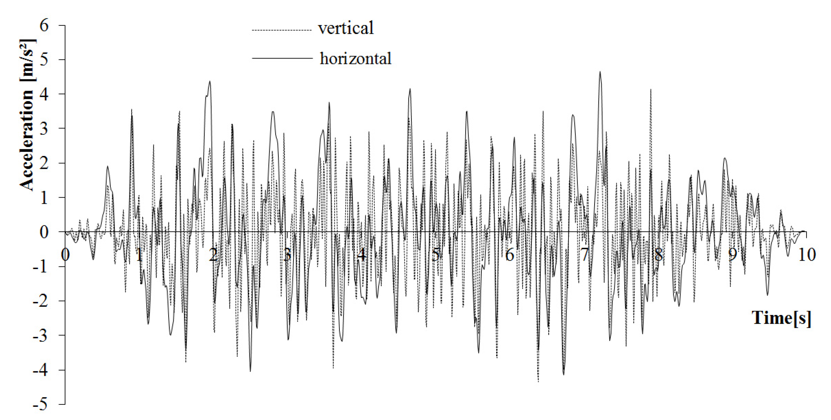
To enable the comparison with transient analyses, synthetically time histories are generated in horizontal and vertical direction (Figure 12) using the elastic response spectra shown in Figure 9.
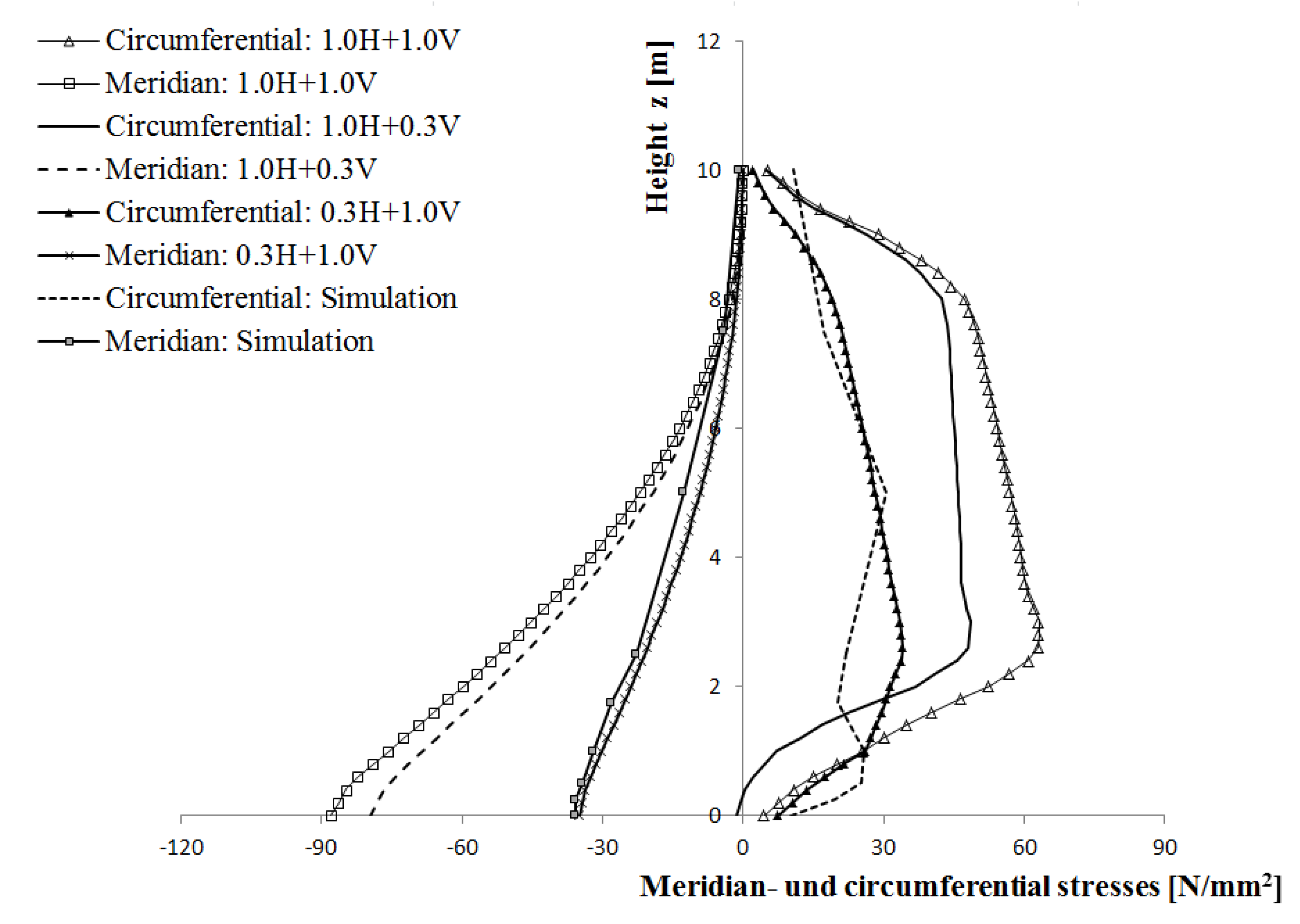
A comparison between the dynamic stresses between the equivalent load method and the non-linear simulation model is provided in Figure 13. As in the non-linear simulation model, the time history is applied as acting in both a horizontal and a vertical direction, it is necessary to make the comparison with the earthquake combinations in both directions. The combination of the directions is based on the 30% rule. Additionally, the full superposition of both of the directions was applied.
The results show considerable differences. The increase factors that were calculated on the basis of the equivalent load method result in a 2–3 times higher factor when compared with the simulation results on the basis of the 30% rule, whereby the combination of 1.0 times the horizontal loads with 0.3 times the vertical loads is decisive. The full superposition provides results that tend to be more certain when compared with the simulation calculation. This is mainly due to the load assumptions of the Eurocode 8, Part 4 [11], which is based on the loads that are to be applied from the horizontal acceleration of the bulk materials being fundamentally transferred from the silo shell to the foundation soil. Contrary to this, it is discernible in the simulation that a substantial part of the horizontal loads due to the acceleration of the material is transferred directly by friction in the foundation soil (or the foundation itself).
This effect is especially pronounced in the squat silo that is being considered here. Its effect decreases the higher the H/D ratio becomes. With the equivalent load method, an attempt is made to do justice to this effect, by a linear progression of the cosine-shaped earthquake load being assumed to exist from the base of the silo up to a defined height. With this reduction of the load applied to the base of the silo considered here, a comparison made with the non-linear simulation under application of the equivalent load method still produces conservative results.
When applied to slender silos, the differences between the calculation methods become considerably less with the equivalent load method reflecting the dynamic stress distribution well. This has been proven by Holler and Meskouris [12] in advanced experimental and numerical studies.
5. Conclusions
The article presents an approach for the seismic calculation of cylindrical silos made of steel containing granular bulk materials. A simplified calculation approach with static equivalent loads is presented for seismic excitation due to the horizontal and vertical direction. In addition, a non-linear simulation model for calculations in the time domain is introduced. The application of the approach with static equivalent loads to a slender silo shows that it is more realistic and economical to determine the acceleration profile along the height of the silo using multimodal analysis on a simplified beam model and not to use a simplified linear acceleration profile as the latter yields results that are too conservative.
A comparison of the results with static equivalent loads and a non-linear simulation model for a squat silo clearly shows that the approach with static equivalent loads yields results with a more than adequate safety margin. The reason for this is that the load approach does not model with adequate precision the fact that, in the case of a squat silo, a large portion of the stress is removed directly through the friction of the bulk material. This results in very conservative stress curves, which in turn can result in uneconomical designs. Here, the use of the nonlinear numerical model can lead to advantages regarding the economical design of the silo structure.
Author Contributions
All authors have conceived and designed the calculation approach, performed the experiments, and analyzed the data. All authors contributed jointly to the writing and preparing revision of this manuscript. All authors have read and approved the manuscript.
Conflicts of Interest
The authors declare no conflict of interest. The founding sponsors had no role in the design of the study; in the collection, analyses, or interpretation of data; in the writing of the manuscript; or in the decision to publish the results.
References
- Rotter, J.M.; Hull, T.S. Wall loads in squat steel silos during earthquake. Eng. Struct. 1989, 11, 139–147. [Google Scholar] [CrossRef]
- Rotter, J.M. Structures, stability, silos and granular solids: A personal adventure. In Structures and Granular Solids: From Scientific Principles to Engineering Application; Chen, J.F., Ooi, J.Y., Teng, J.G., Eds.; Taylor & Francis Group: London, UK, 2008; pp. 1–20. [Google Scholar]
- Rotter, J.M. Silos and tanks in research and practice: State of the art and current challenges. In Proceedings of the International Association for Shell and Spatial Structures (IASS) Symposium 2009—Evolution and Trends in Design, Analysis and Construction of Shell and Spatial Structures, Valencia, Spain, 28 September–2 October 2009; Domingo, A., Lazaro, C., Eds.; Universitat Politècnica de València: Valencia, Spain, 2009. [Google Scholar]
- Yokota, H.; Sugita, M.; Mita, I. Vibration tests and analyses of coal-silo model. In Proceedings of the 2nd International Conference on the Design of Silos for Strength and Flow, Stratford-upon-Avon, UK, 7–9 November 1983; pp. 107–116. [Google Scholar]
- Shimamoto, A.; Kodama, M.; Yamamura, M. Vibration tests for scale model of cylindrical coal storing silo. In Proceedings of the 8th World Conference on Earthquake Engineering, San Francisco, CA, USA, 21–28 July 1984; Volume 5, pp. 287–294. [Google Scholar]
- Sakai, M.; Matsumura, H.; Sasaki, M.; Nakamura, N.; Kobayashi, M.; Kitagawa, Y. Study on the dynamic behavior of coal silos against earthquakes. Bulk Solids Handl. 1985, 5, 1021. [Google Scholar]
- Younan, A.H.; Veletsos, A.S. Dynamics of solid-containing tanks I: Rigid tanks. J. Struct. Eng. 1998, 124, 52–61. [Google Scholar] [CrossRef]
- Veletsos, A.S.; Younan, A.H. Dynamics of solid-containing tanks II: Flexible tanks. J. Struct. Eng. 1998, 124, 62–70. [Google Scholar] [CrossRef]
- Bauer, E. Zum Mechanischen Verhalten Granularer Stoffe unter Vorwiegend ödometrischer Beanspruchungen. Veröffentlichungen des Institutes für Bodenmechanik und Felsmechanik der University Fridericiana in Karlsruhe, No 130. Ph.D. Thesis, Universität Fridericiana zu Karlsruhe, Karlsruhe, Germany, 1992. [Google Scholar]
- Braun, A. Schüttgutbeanspruchungen von Silozellen unter Erdbebeneinwirkungen. Institut für Massivbau und Baustofftechnologie. Ph.D. Thesis, Karlsruhe Institute of Technology, Karlsruhe, Germany, 1997. [Google Scholar]
- Eurocode 8: Design of Structures for Earthquake Resistance—Part 4: Silos, Tanks and Pipelines, German Version EN 1998-4:2006; Deutsches Institut für Normung e.V., Beuth-Verlag GmbH: Berlin, Germany, 2006.
- Holler, S.; Meskouris, K. Granular Material Silos under dynamic excitation: Numerical simulation and experimental validation. J. Struct. Eng. 2006, 1320, 1573–1579. [Google Scholar] [CrossRef]
- Silvestri, S.; Ivorra, S.; Chiacchio, L.D.; Trombetti, T.; Foti, D.; Gasparini, G.; Taylor, C. Shaking-table tests of flat-bottom circular silos containing grain-like material. Earthq. Eng. Struct. Dyn. 2016, 45, 69–89. [Google Scholar] [CrossRef]
- Silvestri, S.; Gasparini, G.; Trombetti, T.; Foti, D. On the evaluation of the horizontal forces produced by grain-like material inside silos during earthquakes. Bull. Earthq. Eng. 2012, 65, 69–89. [Google Scholar] [CrossRef]
- Pieraccini, L.; Silvestri, S.; Trombetti, T. Refinements to the Silvestri’s theory for the evaluation of the seismic actions in flat-bottom silos containing grain-like material. Bull. Earthq. Eng. 2015, 131, 3493–3525. [Google Scholar] [CrossRef]
- Eurocode 1: Actions on Structures—Part 4: Silos and Tanks. German Version EN 1991-4:2006; Deutsches Institut für Normung e.V., Beuth-Verlag GmbH: Berlin, Germany, 2006.
- Eurocode 8: Design of Structures for Earthquake Resistance—Part 1: General Rules, Seismic Actions and Rules for Buildings, German Version EN 1998-1:2004 + AC: 2009; Deutsches Institut für Normung e.V., Beuth-Verlag GmbH: Berlin, Germany, 2010.
- Gudehus, G. A comprehensive equation for granular materials. Soils Found. 1996, 36, 1–12. [Google Scholar] [CrossRef]
- Niemunis, A.; Herle, I. Hypoplastic model for cohesionsless soils with elastic strain range. Mech. Cohesive-Frict. Mater. 1997, 2, 279–299. [Google Scholar] [CrossRef]
- Wagner, R. Seismisch Belastete Schüttgutsilos. Ph.D. Thesis, Lehrstuhl für Baustatik und Baudynamik, RWTH Aachen University, Aachen, Germany, 2009. [Google Scholar]
- Wolf, J.P. Foundation Vibration Analysis Using Simple Physical Models; PTR Prentice Hall Inc.: Upper Saddle River, NJ, USA, 1994; p. 27. [Google Scholar]
- New Zealand Standard 1170.5: Structural Design Actions, Part 5: Earthquake Actions; Standards New Zealand: Wellington, New Zealand, 2004.
- Janssen, H.A. Getreidedruck in Silozellen. Z. Ver. Dt. Ing. 1895, 39, 1045–1049. [Google Scholar]
Figure 1.
Total collapse of a slender silo during the earthquake series in Emilia Romagna/Northern Italy in 2012.
Figure 1.
Total collapse of a slender silo during the earthquake series in Emilia Romagna/Northern Italy in 2012.

Figure 2.
Equivalent static load for cylindrical silos according to Eurocode 8, Part 4 [11].
Figure 2.
Equivalent static load for cylindrical silos according to Eurocode 8, Part 4 [11].
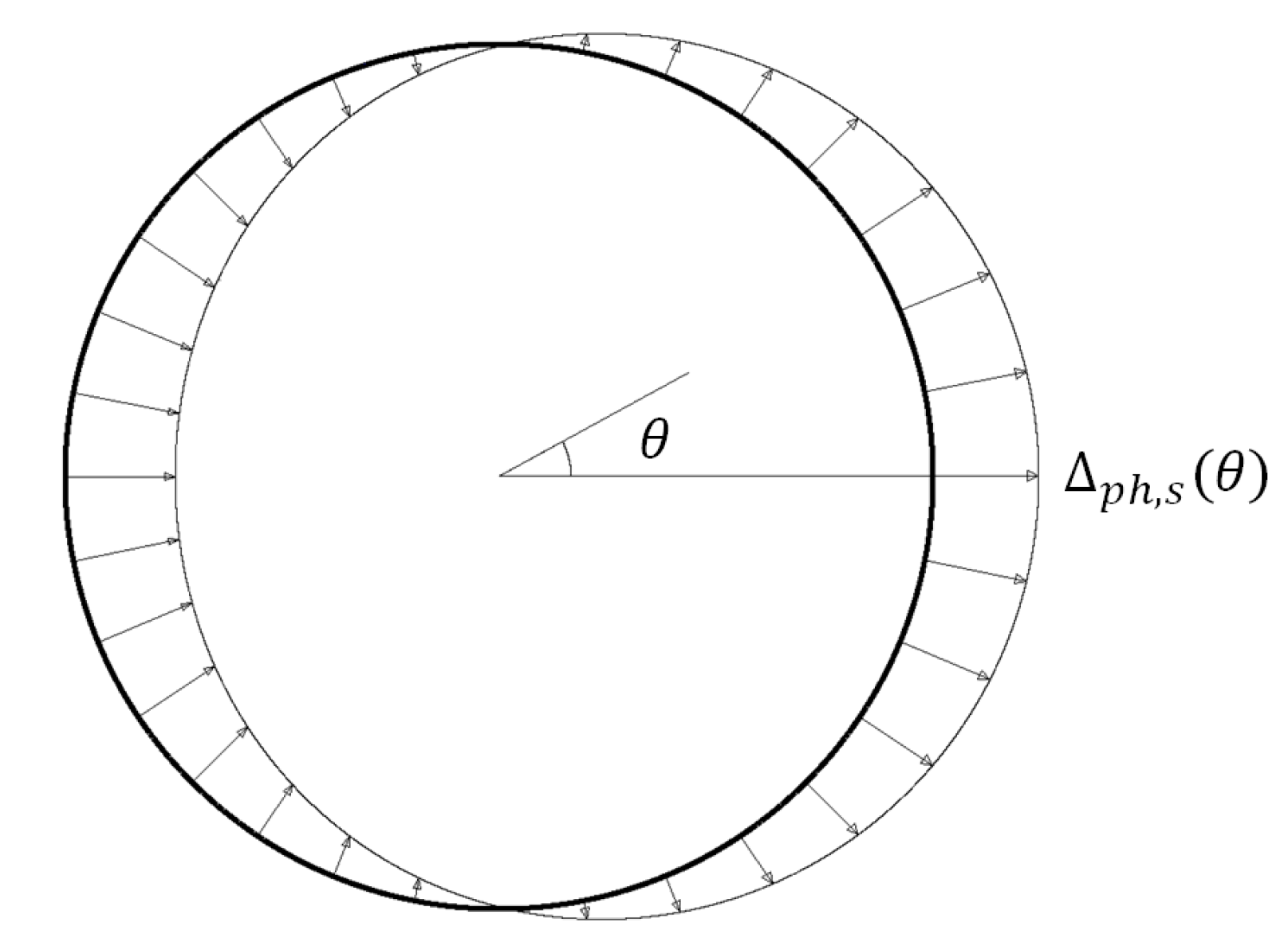
Figure 3.
Pressure distributions—dynamic pressures, pressures due to filling and superposition.
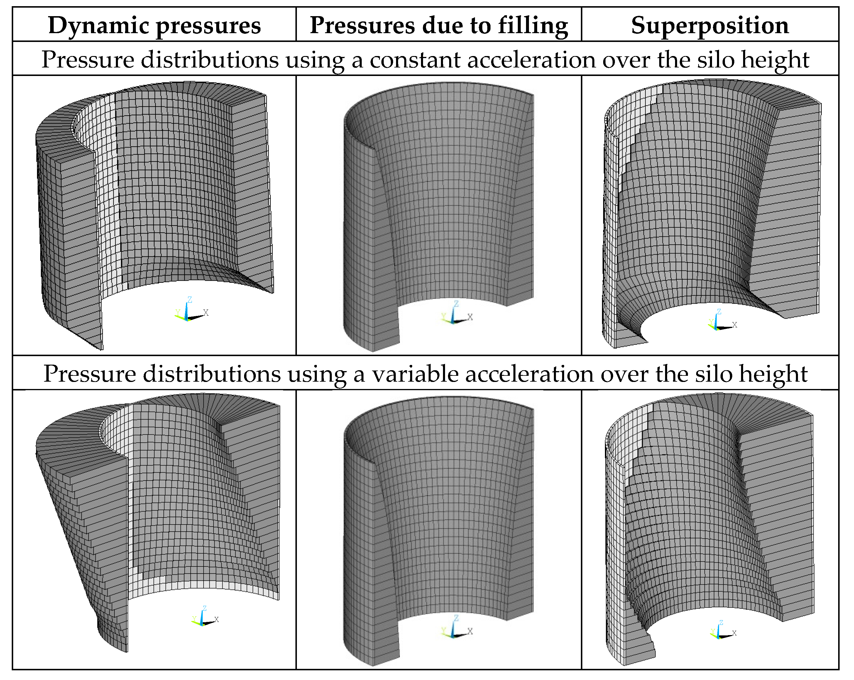
Figure 4.
Nonlinear calculation model.

Figure 5.
Slender silo and idealization as multiple mass oscillator.
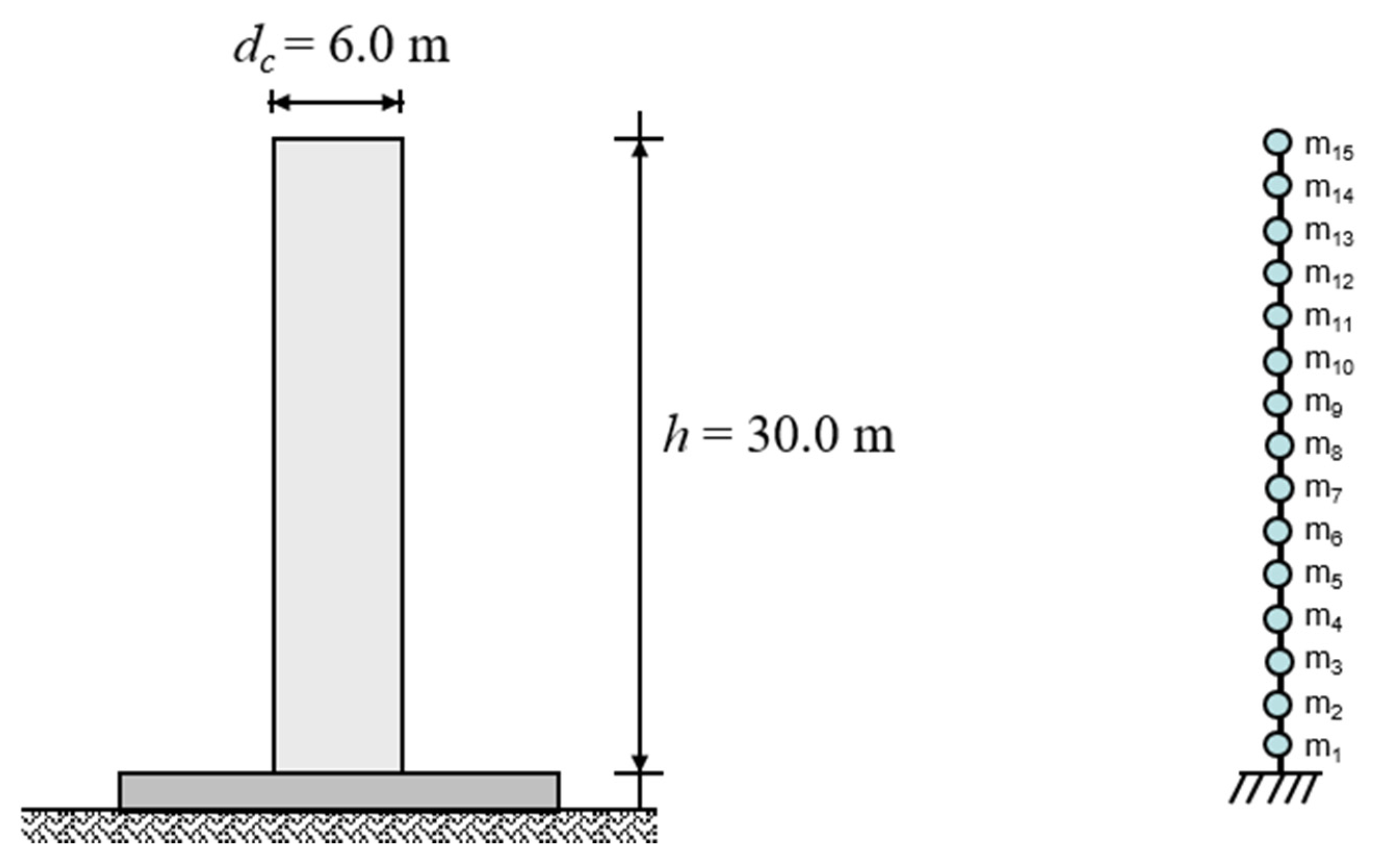
Figure 6.
Design response spectrum according to the seismic code of New Zeeland, Soil Class E [22].
Figure 6.
Design response spectrum according to the seismic code of New Zeeland, Soil Class E [22].

Figure 7.
Linear and multimodal acceleration profile.
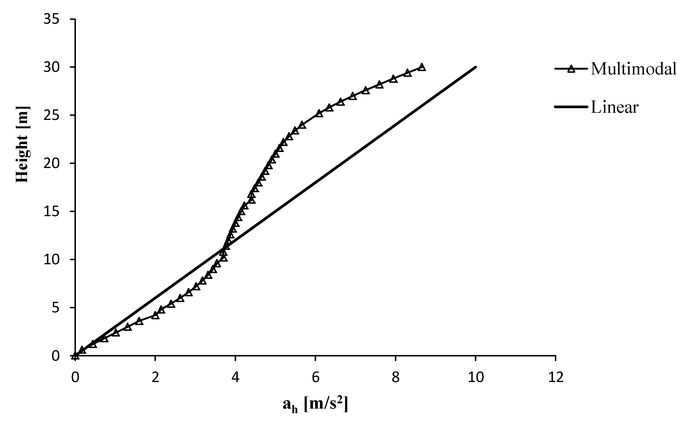
Figure 8.
Circumferential and axial stresses as results of the different approaches of the acceleration.
Figure 8.
Circumferential and axial stresses as results of the different approaches of the acceleration.
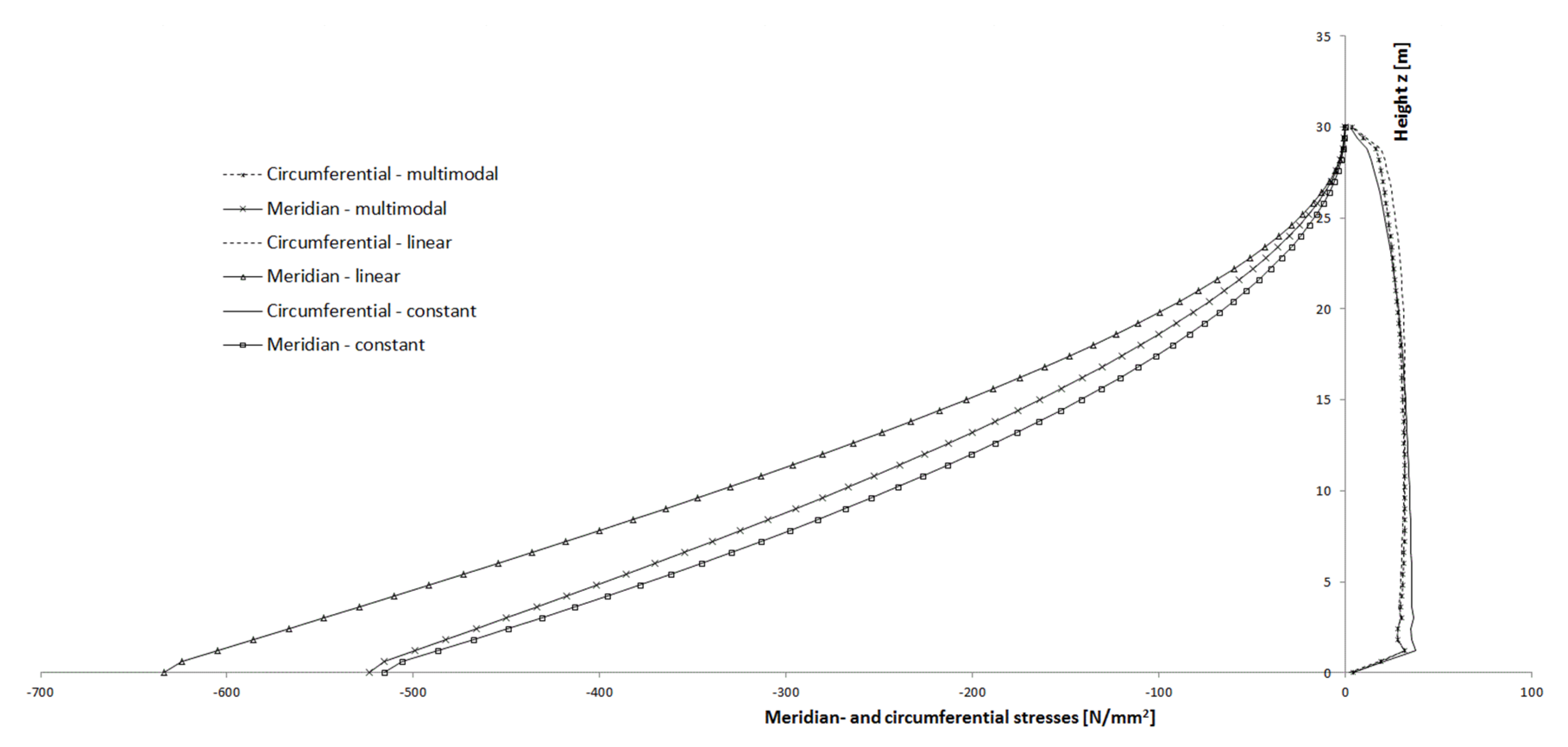
Figure 9.
Elastic response spectrum for the location in Istanbul according to [17].
Figure 9.
Elastic response spectrum for the location in Istanbul according to [17].

Figure 10.
Circumferential and axial stresses due to horizontal seismic excitation.
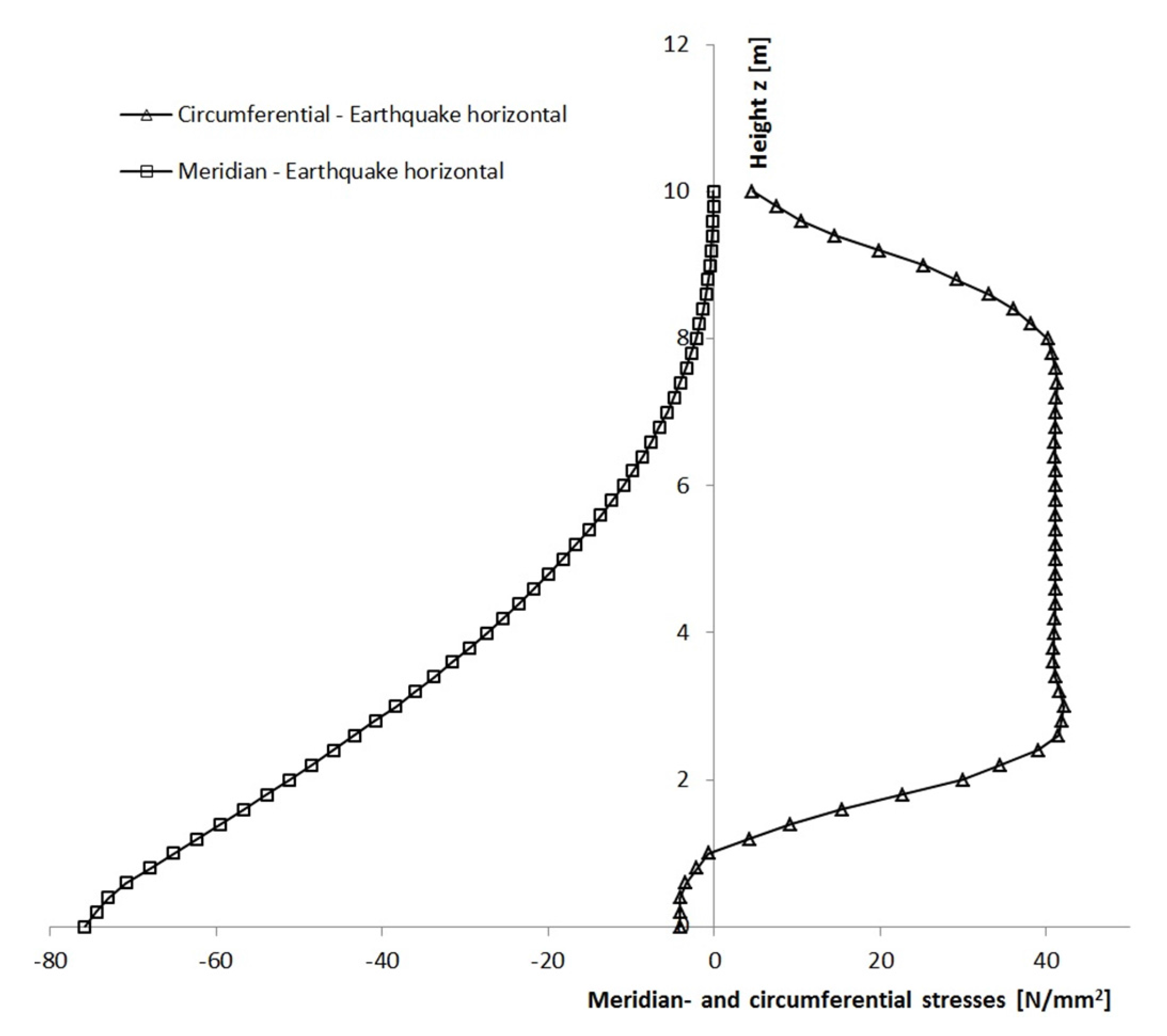
Figure 11.
Circumferential and axial stresses due to vertical seismic excitation.
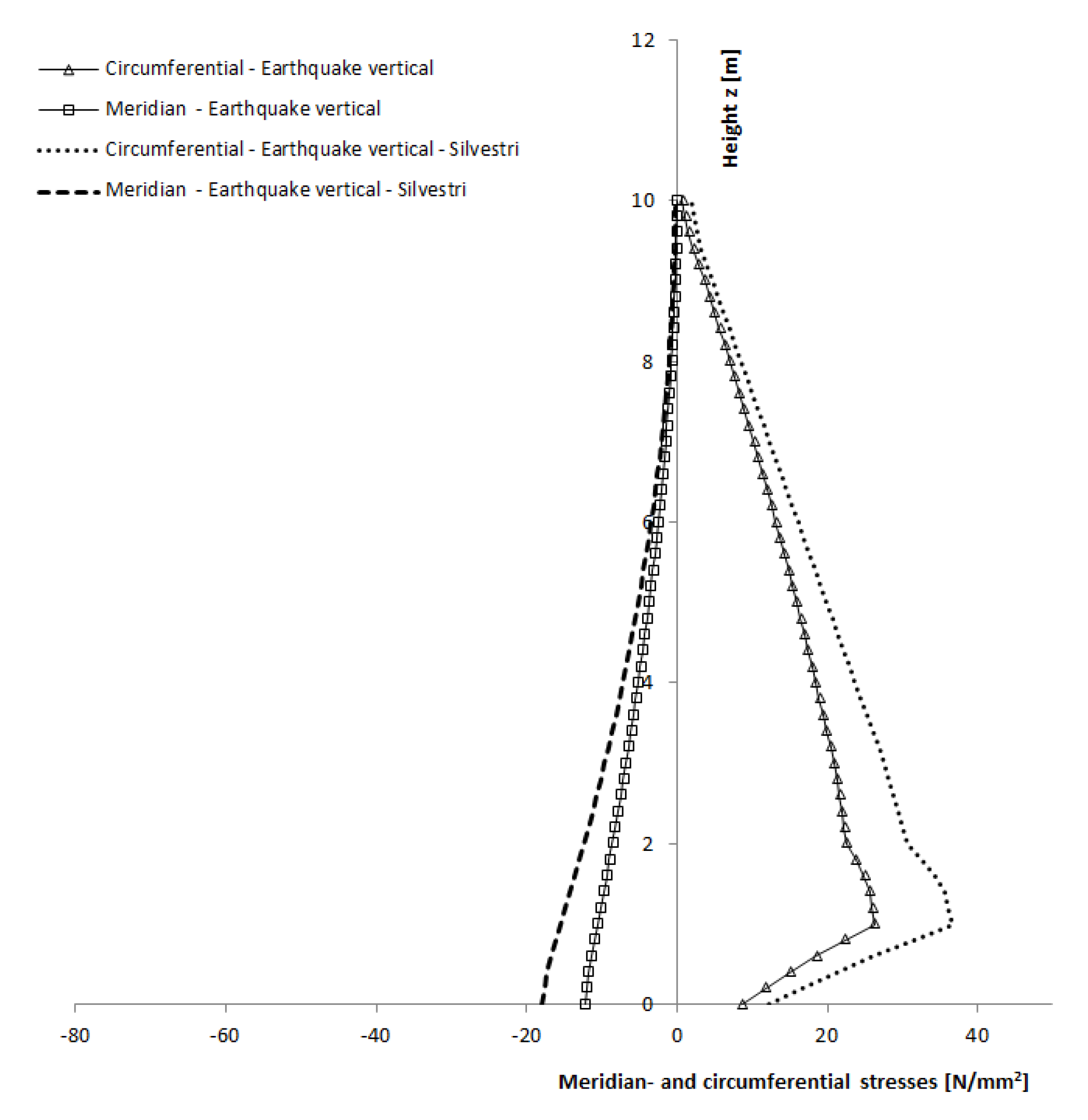
Figure 12.
Synthetically generated acceleration time histories.

Figure 13.
Circumferential and axial stresses due to seismic excitation.

Table 1.
Geometry and material parameter of the slender and squat silo.
| Silos | |||
| Height (squat/slender) | 10.0/30.0 | m | |
| Inner diameter (squat/slender) | 10.0/6.0 | m | |
| Thickness silo wall (squat/slender) | 10.0/8.0 | mm | |
| Young’s modulus | 210.000 | N/mm2 | |
| Poisson’s ratio | 0.3 | [-] | |
| Bulk Material | |||
| Bulk unit weight | γ | 15.0 | kN/m3 |
| Horizontal load ratio | 0.45 | [-] | |
| Wall friction angle | μ | 0.40 | [-] |
| Amplification factor | 1.00 | [-] | |
| Amplification factor pressure on the bottom | 1.00 | [-] | |
© 2017 by the authors. Licensee MDPI, Basel, Switzerland. This article is an open access article distributed under the terms and conditions of the Creative Commons Attribution (CC BY) license (http://creativecommons.org/licenses/by/4.0/).
Share and Cite
MDPI and ACS Style
Butenweg, C.; Rosin, J.; Holler, S. Analysis of Cylindrical Granular Material Silos under Seismic Excitation. Buildings 2017, 7, 61. https://doi.org/10.3390/buildings7030061
AMA Style
Butenweg C, Rosin J, Holler S. Analysis of Cylindrical Granular Material Silos under Seismic Excitation. Buildings. 2017; 7(3):61. https://doi.org/10.3390/buildings7030061
Chicago/Turabian StyleButenweg, Christoph, Julia Rosin, and Stefan Holler. 2017. "Analysis of Cylindrical Granular Material Silos under Seismic Excitation" Buildings 7, no. 3: 61. https://doi.org/10.3390/buildings7030061
Note that from the first issue of 2016, this journal uses article numbers instead of page numbers. See further details here.