Durability of ETICS with Rendering in Norway—Experimental and Field Investigations


1
Department of Civil and Environmental Engineering, Norwegian University of Science and Technology (NTNU), NO-7491 Trondheim, Norway
2
SINTEF Building and Infrastructure, P.O. Box 4760 Torgarden, NO-7465 Trondheim, Norway
*
Author to whom correspondence should be addressed.
Buildings 2018, 8(7), 93; https://doi.org/10.3390/buildings8070093
Submission received: 12 June 2018
/
Revised: 9 July 2018
/
Accepted: 9 July 2018
/
Published: 16 July 2018
Abstract
:External Thermal Insulation Composite Systems (ETICS) with Rendering are widely used in both rehabilitation and new building projects, even in areas with harsh climates such as the western regions of Norway. However, we have seen extensive cases of defects involving such systems. This paper presents a comprehensive review of Norwegian experiences regarding the durability of ETICS on walls. The presented results are based on building research conducted by SINTEF 61 as well as 30 accelerated climatic laboratory experiments over the last 25 years on similar façade systems. These systems generally perform satisfactorily if thoroughly designed and carefully erected. However, according to the survey, the systems are not very robust. Even minor errors in design techniques and/or craftsmanship can lead to rendering defects. The investigations clearly show that ETICS is particularly vulnerable when exposed to severe driving rain conditions. ETICS provides only a single-stage protection against wind and precipitation and do not dry effectively after being wetted. Hence, the resultant cracks and other rendering weaknesses could be disastrous, enabling moisture to penetrate into the thermal insulation and the wall behind. In areas with heavy driving rain, we recommend façade solutions erected in accordance with the principle of two-stage tightening rather than ETICS.
1. Introduction, Objective and Scope
External Thermal Insulation Composite Systems (ETICS) with Rendering are a type of external cladding in which insulation boards are fixed to an outside underlying wall with adhesive, anchors, rails, or a combination of adhesives and mechanical fixings. Reinforced render is applied directly onto the insulation. In North America, such systems are called Exterior Insulation Finish Systems (EIFS). This technique was developed in Germany for extra thermal insulation of masonry walls in the 1950s and 1960s; it also grew popular in Sweden during the energy crisis in the 1970s [1]. The systems were subsequently also introduced on timber frame walls in new buildings [2]. According to Duarte [3], ETICS is currently especially popular in Germany, Poland, and the Czech Republic. Concurrently, several millions of square metres of such systems have been installed in Sweden since 1970. However, in Sweden’s neighbouring country, Norway, ETICS has not been as equally widespread; however, the technique has recently become more established even in this country.
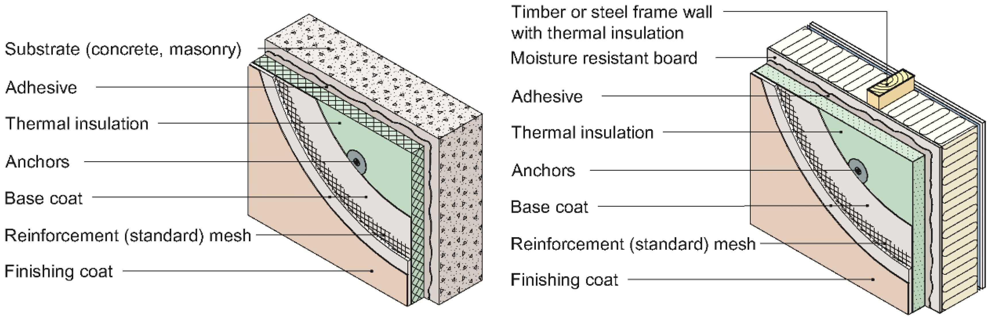
The first systems used in Sweden were based on thermal insulation using mineral wool and a relatively thick layer of render (>15 mm), which was reinforced by metal mesh. The reinforcement and fastening of the system to the underlying structure was formed to allow the render to move relatively freely in relation to the insulation material. Such thick-render systems have virtually disappeared from the market in Norway due to reports of defects as well as a general scarcity of qualified labour. Today, insulation systems typically have a thinner render layer and a glass-fibre mesh instead of metal mesh. According to Blom [4], the elements in present Norwegian systems are as follows (see Figure 1):
- Insulation boards (expanded polystyrene [EPS] or mineral wool) that are glued and mechanically fixed to the substrate.
- Base coat that is either sprayed on the thermal insulation or applied with a trowel/float.
- Alkali-resistant reinforcement (standard) mesh that is pressed into the base coat.
- Key coat (primer) that ensures adhesion between finishing coat and the base coat.
- Through-coloured finishing coat/decorative coat.
- Profiles, anchors, pins, or any special fixing devices used to secure the ETICS to the substrate.
- Supplementary element, component, or product used in the ETICS, e.g., to form joints (mastics, corner strips, etc.) or to achieve continuity (mastic, joint-covers).
This insulation method has many advantages especially in connection with the rehabilitation of older brickwork and concrete walls where it is possible to keep to a rendered façade while achieving substantial added comfort and considerable energy savings. Furthermore, it may solve problems associated with thermal bridges and the repair of defects in older render layers. Façade systems with ETICS can also be used in new building construction.
However, there have been extensive cases of defects involving ETICS systems. Sweden, in particular, has witnessed severe moisture defects and mould growth associated with such systems when applied to thermal-insulated, timber frame walls [5,6,7]. The “Swedish problem” was first discovered in the early 2000s, but the moisture problem was, according to Rudd Hickman [8], already reported in North America at the end of the 1980s. The moisture and mould growth problem has also attracted attention in Germany [9]. Currently, the durability of ETICS and moisture problem is receiving attention even in the Mediterranean area, which has a mild climate with far less precipitation than Nordic countries [10,11,12,13].
The main objective of this study is to review and investigate Norwegian experiences on the durability of ETICS. The presented results are based on laboratory experiments and field investigations carried out by SINTEF over the last 25 years. The laboratory experiments comprise the exposure of ETICS to accelerated climatic loads. Typical problem areas for the systems are presented as well as recommendations for high-performance solutions; however, the effect of the defects on the U-value of the wall is not a part of this study.
2. Methods
2.1. Field Investiagtions: SINTEF Building Defect Archive
SINTEF has been recording cases of building defects for the past 60 years, both on behalf of the building and construction industry as well as through extensive field investigations. Since 1964, more than 5000 assignments associated with process-induced building defect have been carried out [14]. Detailed information regarding these assignments has been collated and filed in a building-defect database. Together with SINTEF Building Research Design Guides (bks.byggforsk.no), this archive represents one of Norway’s most important sources of information concerning types and causes of defects. The SINTEF Building Defect Archive can, for example, be used to:
- identify problem areas,
- develop appropriate preventative measures against certain types of defect,
- determine functional requirements,
- develop strategies and systems for feedback of know-how, i.e., through the further development of SINTEF Building Research Design Guides, national regulations, and standards within Norway’s building and construction industry.
As SINTEF has only investigated a limited number of building-defect cases, this building-defect archive does not adequately describe the extent of building defects in Norway. The likelihood of a given defect to be featured in the archive inversely increases in proportion to the ease of finding a satisfactory solution to the problem; it is also inversely proportional to the ease of attributing responsibility for a given defect.
The expense involved in engaging SINTEF has led to professional players gaining dominance as contract partners. This, in turn, has resulted in a greater likelihood of major and expensive cases of defects featuring in the building-defect file. The price escalation of specialist consultant services will influence customer choice and could also lead to changes in the number and type of defect cases registered in the archive.
The inflow of building-defect assignments is primarily in areas where the industry knows that SINTEF has experts with specialized competence. Changes in the competence profile could lead to changes in the type and number of building-defect assignments. Clearly, one of the major advantages of the archive is the large number of assignments collected over a long period of time. Furthermore, the archive contains thorough descriptions of cause, extent, and preventive actions on complex building-defect cases, investigated and described by highly competent researchers. Despite the presented investigation having some quantitative shortcomings in terms of general validity, it is nevertheless an important step towards a qualitative identification of problem areas. Previous surveys, which were based on the SINTEF Building Defect Archive, include investigations of typical roof defects [15] as well as challenges concerning the design of masonry structures [16].
2.2. Laboratory Experiments: Exposure to Accelerated Climatic Loads
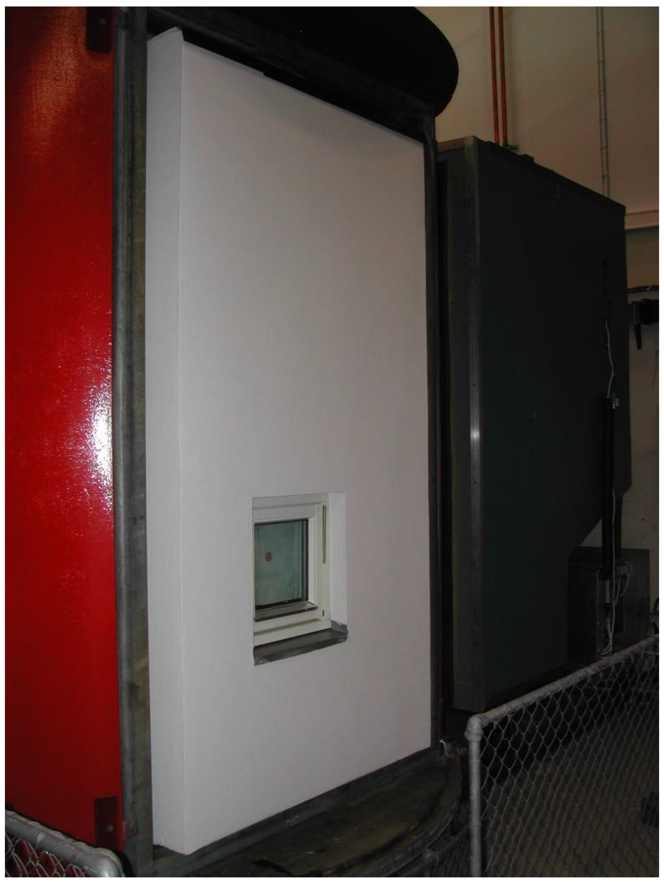
Accelerated artificial climatic ageing of ETICS is usually carried out by SINTEF on three test areas. As shown in Figure 2, the largest test area is 2.4 m high and 1.3 m wide with a window and two smaller objects without a window. The climatic exposure of the largest area lasts 28 days and the purpose of the testing is to review cracking possibilities and defects associated with the installed window. The smaller objects (0.7 m high and 0.6 m wide) are exposed for 18 and 48 weeks, respectively. The experiment provides important information about the long-term durability of the ETICS. The effect on the substrate is not tested nor examined.
Both the large and the smaller façade areas comprise a rear wall in a framework rig with a wind barrier product as support. All installations of ETICS are performed by the supplier in accordance with their own guidelines.
A total of 19 different systems of ETICS have been experimentally investigated by SINTEF during the last 25 years: nine with EPS, seven with mineral wool, and three with polyisocyanurate (PIR) insulation. In addition, 11 systems with rendering on ventilated cladding have been tested, as seen in Figure 3.
The artificial climatic ageing was carried out using the Nordtest method NT Build 495:2000 [17] in SINTEF’s climate simulator (Figure 4). This method was examined by Jelle [19]. This is an apparatus in which specimens can be rotated between four climate zones, as given in the figure. The exposure time was 1 h in each climate zone in the given sequence. Depending on the selected type of UV tube, the UV intensity may be chosen at different levels, e.g., for one specific set of UV tubes, the UVA and UVB intensities were averaged to 15 and 1.5 W/m², respectively.
The ageing factors vary and are dependent on the exposed materials. In practice, the effect of natural ageing on surface treatments is dependent not only on the product that is being used but also on the local climate as well as on both the condition of the substructure and the quality of workmanship. The purpose of the accelerated climatic ageing is to compare the ageing properties of different materials, systems, and techniques. Accordingly, the testing does not provide an accurate estimate of service life expressed in terms of number of years.
3. Results
3.1. Field Investigations
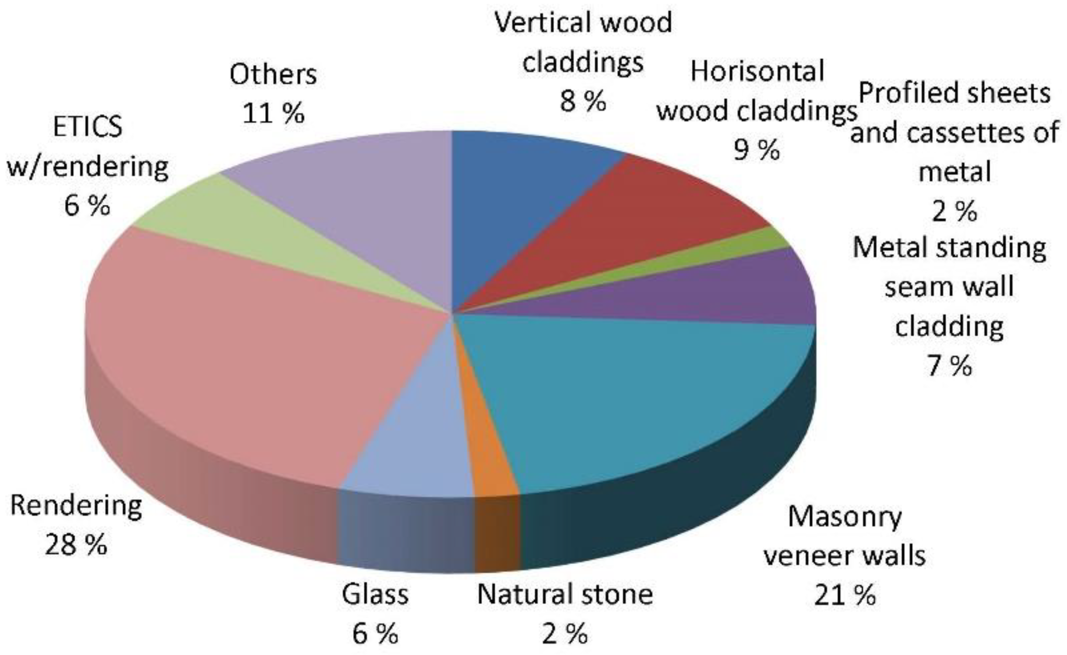
A total of 61 buildings with cases of defects involving ETICS (investigated in the period 1993–2017) were analysed in connection with this investigation. A former study, carried out by Lisø et al. [14] and Lisø and Kvande [20], on the total 1993–2002 selection of building-defect cases, reveals that ETICS comprised 6% of the defect cases SINTEF analysed in connection with external walls above ground during that period (see Figure 5).
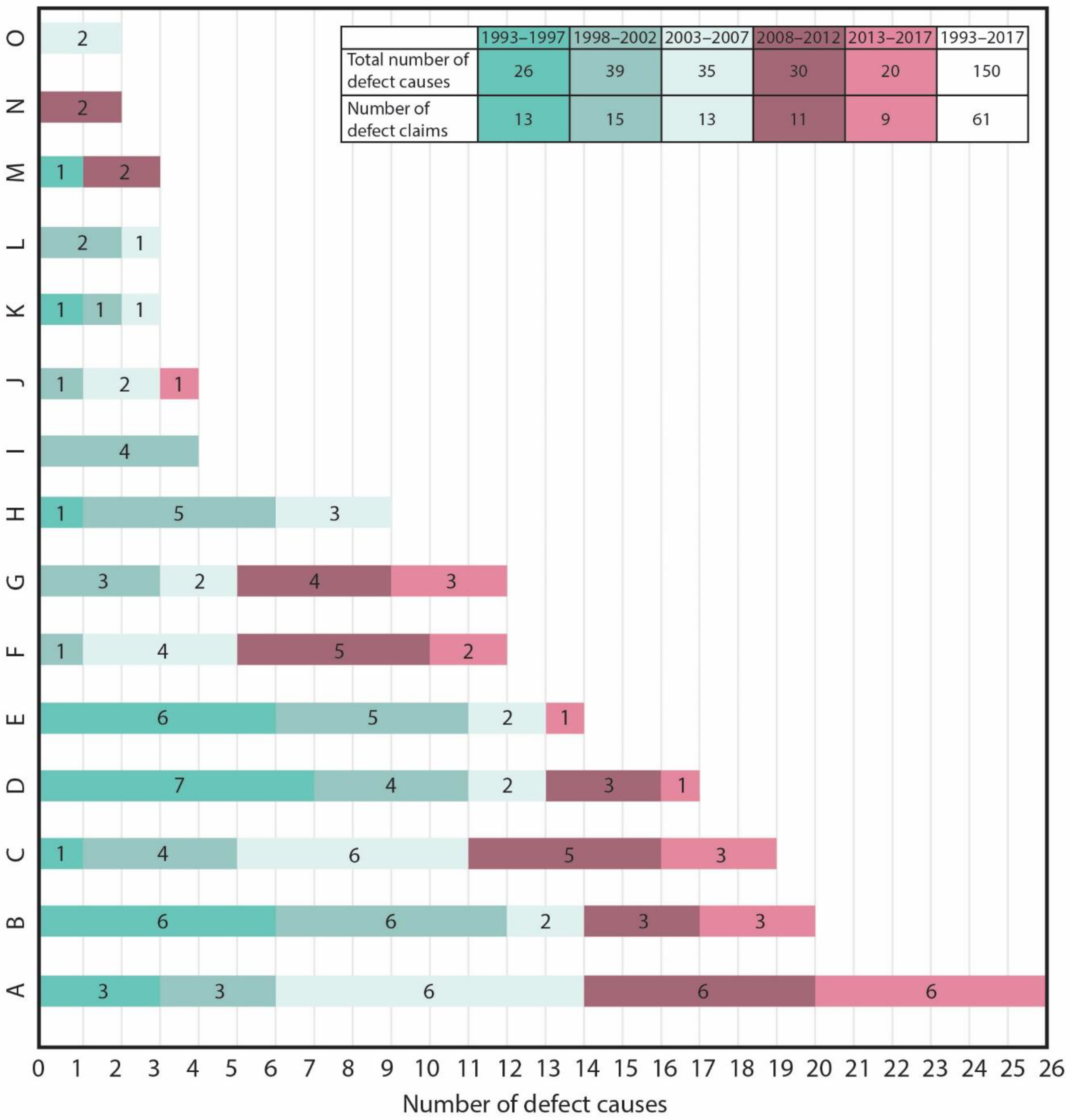
Each of the reports included in the SINTEF Building Defect Archive relates to one defect object (building). The majority of defect cases have been complex, with several causes of defect. Therefore, with regard to ETICS, 150 causes of defect were registered for all 61 defect reports (defect objects). Deficient solutions and/or poor execution were demonstrated by the fact that several conditions failed at the same time. The most prevalent causes of defect for ETICS are ranked in Figure 6. The ranking is based on the total number of defect registrations in the period 1993–2017, but the Figure also gives an indication of the trends by listing the number of defect registrations in five-year periods, e.g., 1993–1997, 1998–2002, 2003–2007, 2008–2012, and 2013–2017, respectively. The causes of defect are grouped together as they appear in the individual defect reports. A short description of the most prevalent causes of defect (A to O) is given in the following:
A. Defects associated with flashings against precipitation
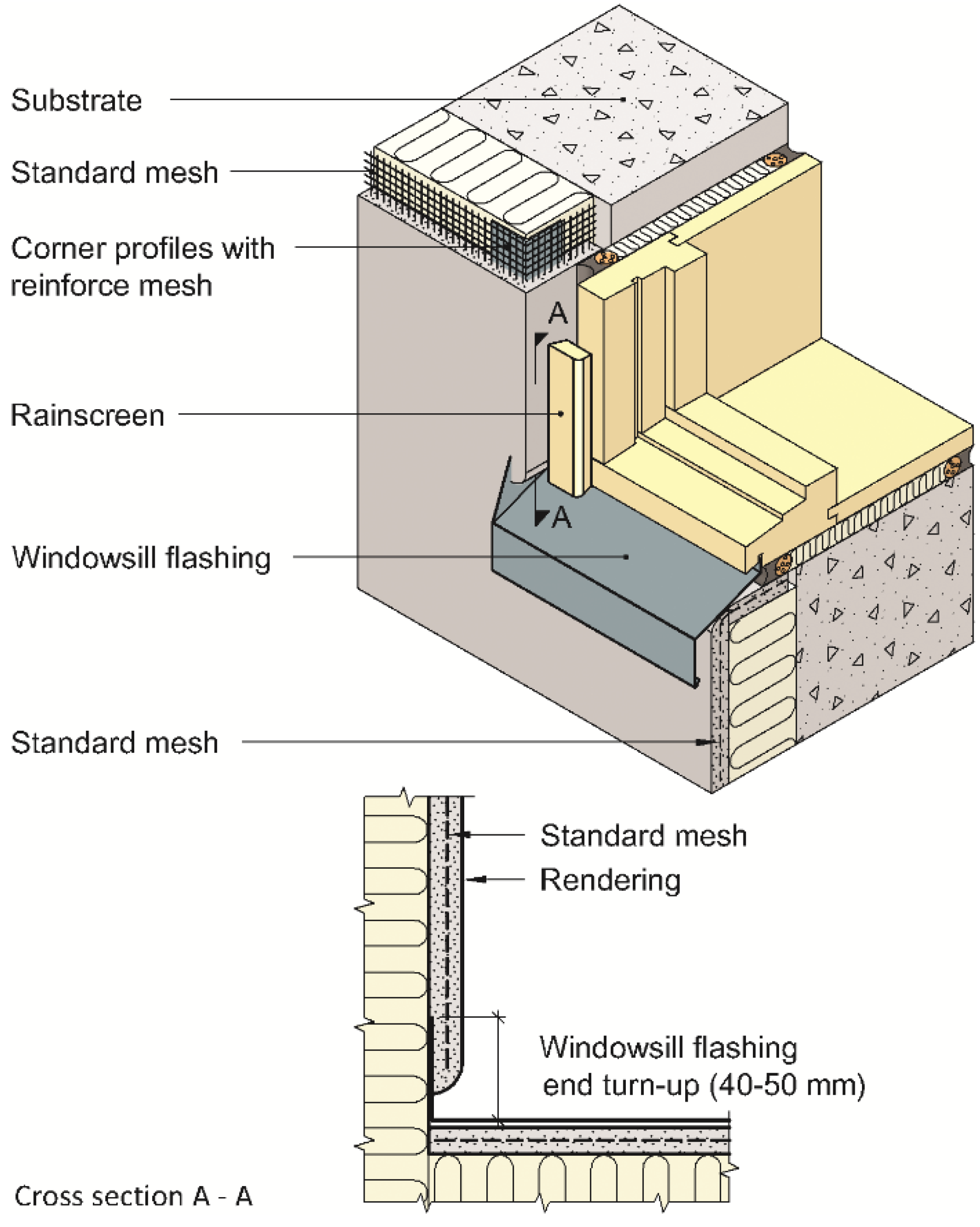
Defective forming and/or execution of cornice, horizontal, parapet, and windowsill flashings are repeated items. Similarly, deficient execution of end flaps against flashings frequently occurs. In addition, deficient roof gutters and drainpipes can impose heavy local loads. Frequently, flashings against precipitation are not adapted to the façade system but are confronted on an individual basis, as seen in the fortunate window solution in Figure 7. Selected references on the causes of defect include Lisø et al. [21].
B. Incorrect reinforcement mesh
This defect is often attributable to the placement of metal mesh or the glass fibre mesh too close to the insulation. Another cause is that the mesh is laid in “waves”, so that it is either touching the insulation or extending too far out in the render layer. In a few cases, the mesh was placed too close to the rendering surface. Reinforcement mesh which has been laid with too little overlap at the joints can easily lead to cracking of the render at the reinforcement joints. Insufficient reinforcement is most prevalent at cut-outs, where extra reinforcement should be introduced, and at render edges, where reinforcement can be too short. In the case of thick render layers, there can also be too little reinforcement in general. Selected references on the causes of defect include Sandin [22].
C. Insufficient thickness of render
Both too thin coarse render and too thin final render are contributory factors in defects. In thin-render systems, the final render is intended to limit moisture loads on the coarse render; therefore, it must cover the entire surface and have a sufficient thickness. Too thin coarse render can easily lead to cracking. Selected references on the causes of defect include Kvande et al. [23].
D. Faulty render mix or undesirable setting conditions
Defects in the actual render or incorrect choice of render are also frequent causes of defect, especially with thick-render systems. The archive includes examples of the unfortunate choice of acrylic render which swells when moist, often resulting in reduced solidity and increased moisture permeability. Direct sunlight on and/or wind along a fresh render surface can result in premature drying, usually characterised by crazing and low solidity. Rendering at too low temperatures is undesirable. It can lead to premature freezing of the rendering mortar. The result is often minimal adhesion to the substructure and excessive porosity. Selected references on the causes of defect include Kvande et al. and Sandin [24,25].
E. Shrinkage and temperature movements in the render
This defect can be caused by deficient expansion joints and render with great shrinkage potential due to excessive binding-agent content. Too high binding-agent content applies first and foremost to thick-render systems. Deficient expansion joints are obviously more common in lime and cement-based rendering systems than in acrylic-based rendering systems. Selected references on the causes of defect include Kvande et al. and Østergaard et al. [26,27].
F. Incorrect end laps against adjoining structures
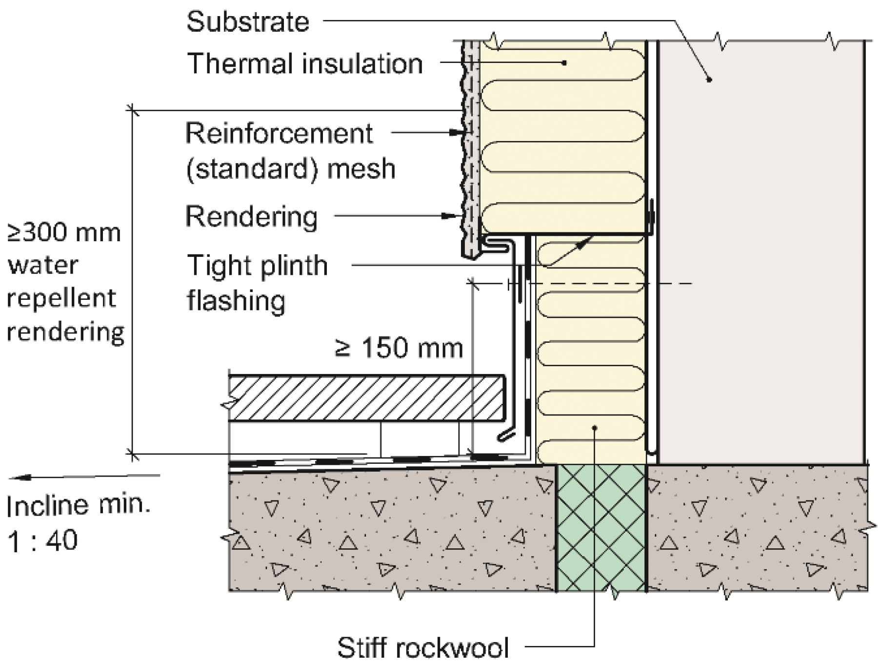
Insufficient transitions to balconies and other façade materials often lead to moisture problems in the structure. Examples of fortunate transition solutions are provided in Figure 8 and Figure 9. Selected references on the causes of defect include Kvande et al. [28].
G. Moisture from the ground (render down in the soil)
Render which enters the ground provides an opportunity for moisture to be drawn up from the soil (capillary action) unless preventative measures are introduced. Frost deterioration in the render is a common result. Selected references on the causes of defect include Groota et al. [29].
H. Faulty anchorage of the system
Insufficient or incorrectly positioned anchorage of the thermal insulation can lead to unwanted deformations in the façade system, resulting in cracking of the render. Furthermore, the use of thick-render systems (thickness > 15 mm) without anchorage of the reinforcement mesh to the wall behind or the use of thin-render systems with anchorage of the reinforcement mesh to the wall behind can cause render defect. Selected references on the causes of defect include ETAG 004:2013 and Guo et al. [30,31].
I. Microorganism growth in/on the render
Biological growth is not unusual in damp and mild climates. Render with large quantities of organic additives have proved to be highly vulnerable as growth can cause swelling of such render. Selected references on the causes of defect include Stazi et al. and Johansson et al. [10,32].
J. Variations in render thickness over the insulation boards
Large divergences in render thickness can cause cracking. Such divergence can occur at joints in the insulation boards and are most common when using mineral wool. Selected references on the causes of defect include Kvande et al. [24].
K. Vibrations, movements in the substructure, settling
Vibrations and other movements in the wall behind can easily cause cracking of the render. Selected references on the causes of defect include Kvande et al. [24].
L. Incorrect choice of paint or incorrect cleaning prior to painting
Moisture accumulation behind the paint layer or deficient cleaning prior to painting can cause defects in the form of flaking and possibly frost deterioration to the render. Selected references on the causes of defect include Šadauskienė et al. [33].
M. Insufficient impact resistance
Ground-level zones readily accessible to the public may be especially vulnerable to hard body impacts and to perforation. Selected references on the causes of defect can be found in ETAG 004:2013 [30].
N. Leaching of pigment
Heavy water exposure may cause leaching of pigment if the rendering is insufficiently composed. Selected references on the causes of defect include Schoknecht et al. [34].
O. Mould growth behind the ETICS
Mould growth is often caused by the accumulation of moisture in organic materials in the primary wall. Selected references on the causes of defect include Samuelson et al. [2].
3.2. Laboratory Experiments
Typical weak points revealed through the accelerated climatic ageing are largely associated with execution details or accessories (components) that comprise the system (weather-protective flashing, corner mouldings, and jointing strips). The following improvement measures are repeatable items:
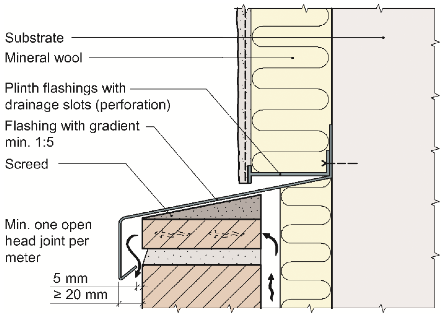
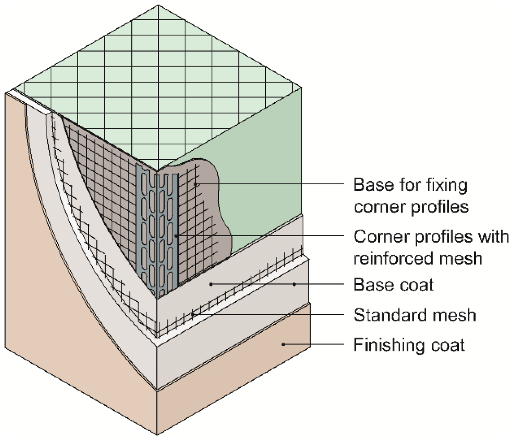
- The most vulnerable points for a façade system are the edges/corners. It is imperative to use corner profiles and plinth flashings that work well with the render and give reduced risk of cracking. Figure 10 shows an example of recommended corner reinforcement which was developed based on the laboratory testing and field experiences.
- Omission of plinth flashing always leads to severe water exposure at the edge of the render and consecutive frost damage. Similarly, unsatisfactory design of the drip edge of the plinth flashing prevents water from flowing away from the building in a proper manner.
- The transition to the plinth flashing at the base of the façade system can be challenging because the reinforcement mesh tends to be drawn too far up during erection of the mesh. The mesh ought to overlap the flashing to prevent cracking.
- It is essential to use plinth flashings with drainage slots (perforation) to ensure that water is drained away from the mineral wool. This is not necessary in the case of EPS insulation.
- Many render systems require paint application or a special finishing coat. To sufficiently safeguard the base coat, it is important that paint/finishing coat treatment is also applied to the lower edge of the base coat (against the plinth flashing).
- Unless the boards are laid closely together and are at the same level, the joints between the thermal insulation boards can lead to cracked/weakened areas. The same applies if joints in the reinforcement mesh are allowed to lie over board joints without a generous overlap.
- Reinforcement mesh are often positioned too close to the thermal insulation layer, thus limiting the effectiveness of the reinforcement mesh.
- Achieving a good transition to a windowsill flashing in a thin-render system is a challenging task. See example in Figure 7.
- Ageing properties for systems with render on EPS are generally better than those with render on mineral wool.
4. Discussion and Limitations
4.1. Comparative Studies
Amaro et al. [12] describes an inspection and diagnosis system of ETICS on walls, which enables facilitating and standardising inspection, diagnosis, and repair. The system is validated through an inspection programme undertaken on 14 buildings/sets of buildings comprising 146 façades, largely from the surrounding area of the Portuguese cities Porto, Lisboa, and Coimbra [35]. The presented review does not follow the inspection and diagnosis system proposed by Amaro et al. [12]. This is because the SINTEF assignments reports follows SINTEF’s own system for inspection and diagnosis which is independent of type of material and structure and less focused on aesthetic anomalies [14]. It was not convenient to rearrange the survey according to Amaro et al. [12]. The system proposed by Amaro et al. does not include the substrate and incidents during the building process in the diagnosis, which is a part of the review made by SINTEF. However, it is still of interest to compare the present review with the general results from the survey of Amaro et al. [12,35].
According to Amaro et al. [35], the predominant sensitive issues of ETICS in Portugal are colour/aesthetic anomalies (49%), flatness anomalies (27%), and materials rupture anomalies (24%). The most frequent anomaly was determined to be biological growth, which was present on more than half of the inspected façades. Cracking is the most common material rupture anomaly, present on about 40% of the façades. The situation is quite different from the present review, where absence of biological growth is the most noticeable. The cold Norwegian climate is the main reason for the lack of biological growth. Climate conditions also explain the Norwegian focus on defects associated with flashings and rain penetrations. The study of Amaro et al. [35] further highlights the importance of a correct maintenance plan, which is supported by the present review.
An ETICS survey from a more climatic comparable area to Norway was carried out in Sweden on 821 buildings [2]. The survey counted only the substrate of timber or steel frame walls (Figure 1). However, the most frequent defect causes, which were revealed in a study by Samuelson and Jansson [2], support the present review, with defects associated with flashings against precipitation as the most frequent. It also confirms that even small cracks and holes may lead to moisture damage. However, the Swedish survey reveals an alarmingly high occurrence of mould growth behind the ETICS which is rarely observed in Norway. It is also of interest that Samuelson and Jansson did not reveal any damages in the north of Sweden. The reason that there were no reported damages in northern Sweden is not explained, but the selection of building from the north of Sweden was small (five buildings), and the results might have been influenced by coincidences.
4.2. Thickness of Rendering System
A small share of the knowledge base in the SINTEF Building Defect Archive is associated with thick-render systems (render thickness > 15 mm). As a result of poor previous experience with cracking, such systems are not currently used in Norway. This is evident from the observed reduction of cases of defect with faulty render mixtures or undesirable setting conditions as well as with rendering shrinkage and temperature movements (defect causes D and E in Figure 6). Instead, the number of faults in connection with flashings against precipitation has increased, which might be affected by the increasing share of thin-render systems. Thin-render systems are vulnerable to moisture penetration if the final render is applied so thinly that it does not provide a complete covering outer layer (cause C). Furthermore, thin-render systems can be more challenging, with a view to achieving good transitions to flashings against precipitation (cause A) and transitions against adjoining structures (cause F).
4.3. Minor Deviations and Cracking
An initial comparable investigation of cracks on ETICS presented by de Freitas [13] examined systems with extruded polystyrene (XPS) only, which is not used in Norway. Hence, the mechanical behavior described by [13] is less relevant because of the higher stiffness of XPS than of EPS and mineral wool. However, ETICS is generally vulnerable to small deviations in execution. Even minor deviations can result in cracking of the render with subsequent moisture penetration, reduced insulation value, and further deterioration of the render. The problem with render cracking can be limited by its use, with only a minor shrinkage potential and to which fibre or mesh reinforcement can be added, placed in the middle of or in the outer part of the coarse render. This technique is confirmed by examinations carried out by Sandin [22]. Furthermore, the experience of the authors is that premature drying of the render is undesirable as a method to avoid cracking. However, according to Sandin, premature drying can be an advantage. The general recommendation of Kvande et al. [24] is that render should be kept moist by applying water for at least three days and be protected against precipitation and direct sunlight for at least two weeks. These recommendations are dependent on the type of render applied. Blom et al. [18] provide detailed instructions for the execution of façade systems using ETICS.
4.4. Thermal Insulation Impact
The ageing properties of systems with rendering on EPS are generally found to perform better than those with rendering on mineral wool. The difference is revealed both in building-defect experience and through accelerated climatic ageing. The main reasons for the difference can be associated with the difference in substructure. Whereas EPS absorbs very little water, mineral wool can absorb large quantities of water. This means that more water is drawn out of the fresh rendering mortar before/during setting. Too little water in the mortar during the hardening process can lead to a more porous render. Furthermore, installing mineral wool boards with plane surface is more challenging than the installation for EPS. Accordingly, mineral wool board may make an unfavourable substrate for the rendering because of the high risk of cracking during the hardening process of the mortar. In addition, mineral wool can absorb more moisture than EPS, causing slow drying of the ETICS and presenting a higher risk for frost damage of the rendering. The U-value is also affected negatively by the moisture content of the insulation.
In Sweden, there has been a focus on possible mould damage to timber framework walls with ETICS [2,6,7]. The present survey revealed only one incident of mould damage on the wind barrier board behind the EPS insulation. In this case, the wind-barrier board was installed on a concrete balcony floor without any protective membrane, i.e., due to poor building design. The second mould example was caused by a lack of weather protection during construction. In other words, the same tendency of mould damage, as reported from Sweden, is not seen in Norway. This is also likely influenced by by the fact that masonry and concrete is more common substrate for ETICS in Norway than in Sweden.
4.5. Driving Rain Challenges
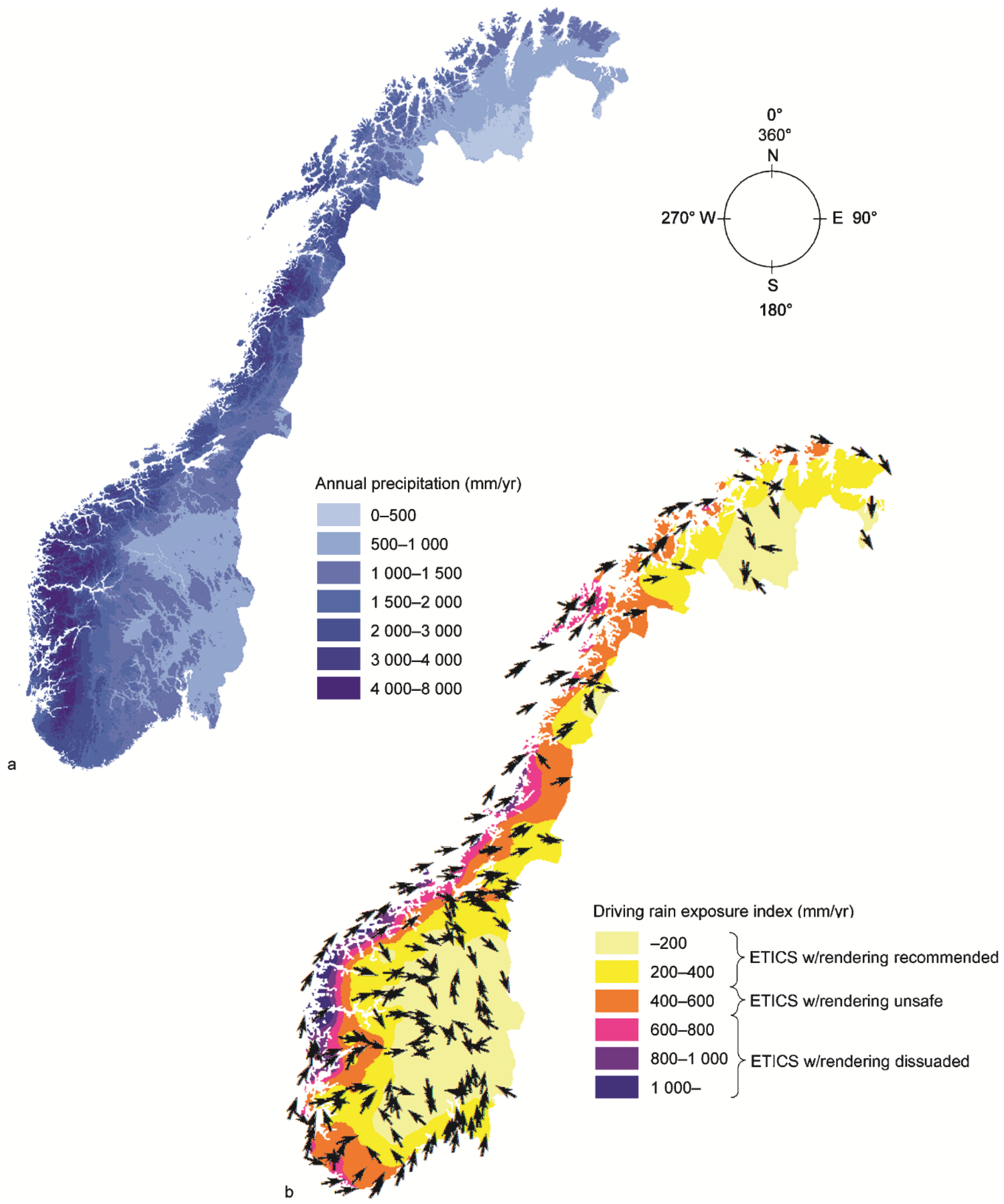
According to Köhler [7], most moisture defects in Sweden are found in buildings on the west coast, from Skåne to northwards of Gothenburg. There is a clear connection between driving rain loads and the extent of leakages. The same pattern can be seen from a survey of Norway, yet the extent of mould damage is small. The greatest moisture defect is found in areas exposed to considerable driving rain loads. Figure 11 provides the annual precipitation of Norway as well as the driving rain amount and the dominant driving rain direction. The driving rain map presents annual driving rain amounts (illustrated by colour scale) from the main wind direction (indicated with arrows) that gives the highest driving rain amounts at each observing station [36]. The map provides driving rain exposure on the wall in mm/year. Topographic effects were not considered. Therefore, some locations may be more or less protected than the map expresses.
4.6. ETICS Recommendations Dependent on Driving Rain Exposure
ETICS provides only single-stage protection against wind and precipitation, which implies the render has to stop both the wind and the rain exposure. The consequences of cracked/weakened areas in the render are quite considerable. According to Kvande and Lisø [16], the employment of the two-stage tightening principle is crucial in climates with severe driving rain exposure (driving rain exposure index >400 mm/year., see Figure 11). The principles of two-stage tightening implies protection by a separate rain shield (cladding) and air/wind tightening (wind barrier). Climatic classification by driving rain exposure is given by Kvande [37]. The ETICS recommendations for use in different parts of Norway, given in the figure, are based on the results from this survey:
- “Recommended” when driving rain exposure <400 mm/year,
- “Unsafe” when driving rain exposure 400–600 mm/year,
- “Dissuaded” when driving rain exposure >600 mm/year.
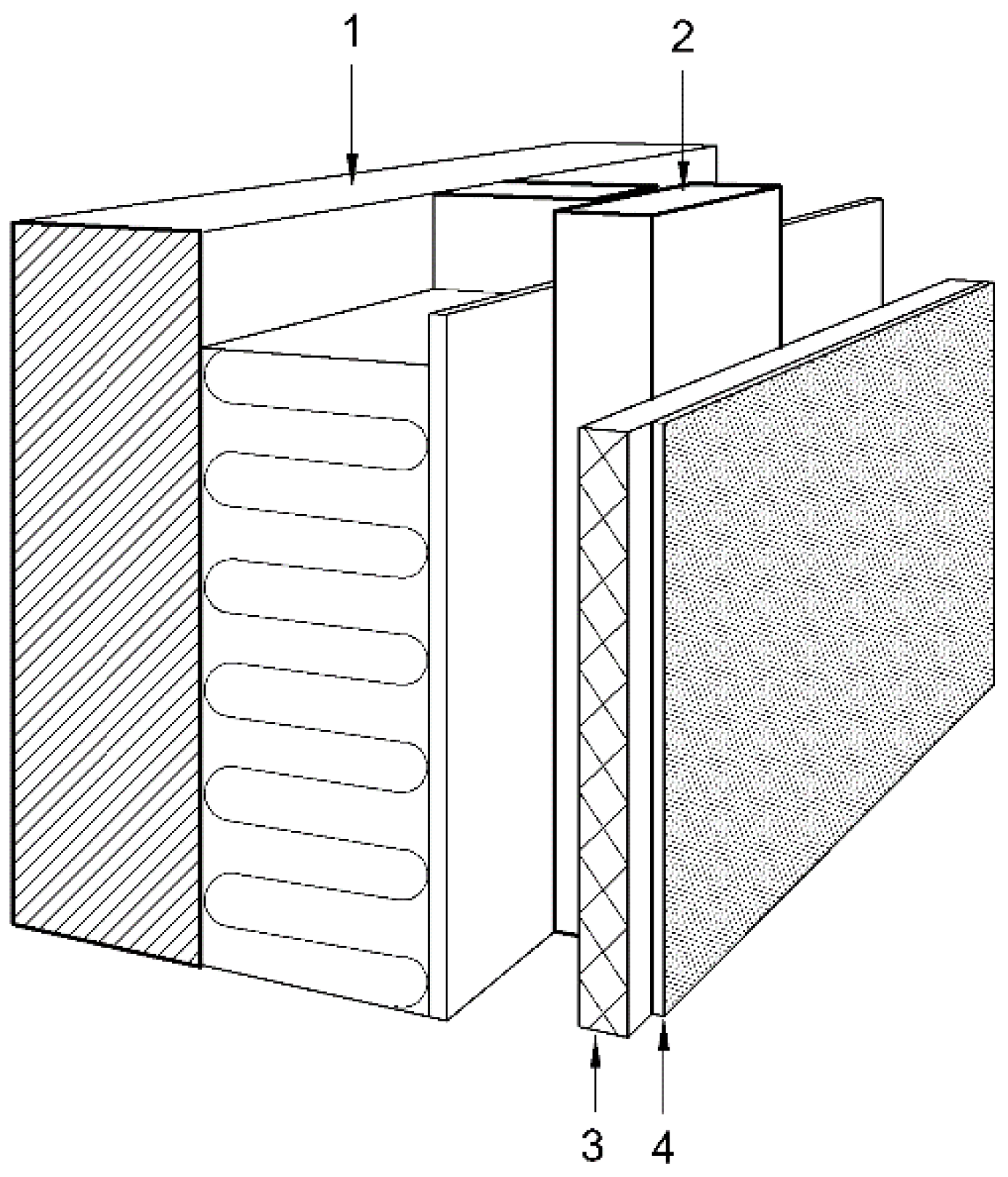
A façade constructed according to the principles of two-stage tightening is far more secure against moisture penetration than a single-stage protection against wind and precipitation [20]. An alternative to ETICS is render applied to ventilated cladding consisting of moisture-resistant wallboards (see Figure 3). Fibre-reinforced calcium silicate or crushed returned glass are good examples of moisture-resistant board materials according to the laboratory experiments. This alternative also provides a joint-free, rendered façade and, at the same time, adheres to the principles of a two-stage tightening. i.e., ventilating cladding provides better resistance against moisture defects than ETICS. It is also conceivable that render on ventilated cladding has a somewhat better resistance against fungus and algae damage in the final render due to faster drying of the render and render substructure after rain exposure.
5. Conclusions
Many of the ETICS perform satisfactorily in parts of Norway; it is often a good and effective way with which to insulate. However, this survey has shown that such façade systems are vulnerable in areas with heavy driving rain loads. The technique provides only single-stage protection against wind and precipitation. Hence, the consequences of cracked and weakened areas in the render are considerable. Results from this survey and previous research shows that façade systems with ETICS do not dry effectively after being wetted by rain exposure; therefore, these systems are highly vulnerable to moisture that penetrates into the insulation layer. On the basis of this survey, the geographically dependent ETICS recommendations are classified in three different categories (“recommended”, “unsafe”, and “dissuaded”), dependent on the amount of driving rain exposure.
The review has shown that one frequent cause of defect is the incorrect assembly of the components of the ETICS. Recognised systems must be used where all the components fit properly together and have documented product characteristics.
A preferred alternative to ETICS in harsh climates is render on ventilated cladding using moisture-resistant (building) wall boards (e.g., fibre-reinforced calcium silicate or crushed recycled glass). Similar to ETICS, this solution provides a joint-free, rendered façade while maintaining the principles of two-stage tightening. The principles of two-stage tightening imply protection by a separate rain shield (cladding) and air/wind tightening (wind barrier). In areas exposed to heavy driving rain loads, façade solutions performed according to the principles of two-stage tightening instead of façade systems using ETICS should be preferred.
Author Contributions
T.K. initiated and carried out the main bulk of the research. He was responsible for the literature review, data analysis, and drafting the article. N.B. was responsible for most of the laboratory testing and several of the assignments of building defects on which this research article is based. He also contributed to the analysis and interpretation of the results. E.B. served as the main supervisor of the laboratory testing during the process and conducted the first testing. J.V.T. contributed to the research design and the analytic cohesion of the analysis. All the co-authors provided critical comments on the prepared manuscript by T.K. during the process, and they have all given final approval of the version to be published.
Funding
This research is funded by the Research Council of Norway.
Acknowledgments
The authors gratefully acknowledge the financial support by the Research Council of Norway and several partners through the Centre for Research-based Innovation “Klima 2050” (see www.klima2050.no). A special thanks to Bjørnar Nørstebø and Remy Eik at SINTEF for help with making the images, and to Kim Robert Lisø for feedback on the text.
Conflicts of Interest
The authors declare no conflict of interest.
References
- Elmarsson, B. Puts på tilläggsisolering: Tio Experimentbyggnadsprojekt för Prov av Olika Metoder [ETICS w/rendering: Ten Cases]; T5; Byggforskningsrådet: Stockholm, Sweden, 1979. [Google Scholar]
- Samuelson, I.; Jansson, A. Putsade Regelväggar [ETICS on Framework Walls]; SP Rapport 2009:16; SP Technical Research Institute of Sweden: Borås, Sweden, 2009. [Google Scholar]
- Duarte, C. A Europa das argamassas e dos ETICS. Tendências, perspectivas e oportunidades. [The Europe of mortars and ETICS. Trends, perspectives and opportunities]. In Proceedings of the IX SBTA—Brazilian Symposium on Mortars Technology, Belo Horizonte, Brazil, 18 May 2011; pp. 7–16. [Google Scholar]
- Blom, P. Fasadesystemer med puss på isolasjon [ETICS]. In SINTEF Building Research Design Guide; 542.303; SINTEF Building and Infrastructure: Oslo, Norway, 2010. [Google Scholar]
- Samuelson, I.; Wånggren, B. Fukt och Mögelskador i Hammarby Sjöstad [Moisture- and Mould Damage in Hammarby Sjøstad]; SP Rapport 2002:15; SP Technical Research Institute of Sweden: Borås, Sweden, 2002. [Google Scholar]
- Samuelson, I.; Mjörnell, K.; Jansson, A. Fuktskador i Putsade, Odränerade Träregelväggar [Defect on Timber Framework Walls with ETICS]; SP Rapport 2007:36; SP Technical Research INSTITUTE of Sweden: Borås, Sweden, 2007. [Google Scholar]
- Köhler, N. Fortfarande Fuktiga Fasader—Nio Månader efter Larmet [Moisture in Façades—Nine Months Afterwards the Moisture Alarm]; Byggindustrin: Stockholm, Sweeden, 2008; pp. 14–19. [Google Scholar]
- Rudd Hickman, A. Insurers Slapping EIFS Exclusions on Insurance Policies; International Risk Management Institute, Inc.: Dallas, TX, USA, 2004. [Google Scholar]
- Künzel, H.; Zirkelbach, D. Influence of rain water leakage on the hygrothermal performance of exterior insulation systems. In Proceedings of the 8th Symposium on Building Physics in the Nordic Countries, Copenhagen, Denmark, 16–18 June 2008; pp. 253–260. [Google Scholar]
- Stazi, F.; Di Perna, C.; Munafò, P. Durability of 20-year-old external insulation and assessment of various types of retrofitting to meet new energy regulations. Energy Build. 2009, 41, 721–731. [Google Scholar] [CrossRef]
- Barreira, E.; de Freitas, V.P. Experimental study of the hygrothermal behaviour of External Thermal Insulation Composite Systems (ETICS). Build. Environ. 2013, 63, 31–39. [Google Scholar] [CrossRef]
- Amaro, B.; Saraiva, D.; de Brito, J.; Flores-Colen, I. Inspection and diagnosis system of ETICS on walls. Constr. Build. Mater. 2013, 47, 1257–1267. [Google Scholar] [CrossRef]
- De Freitas, S.S.; de Freitas, V.P. Cracks on ETICS along thermal insulation joints: Case study and a pathology catalogue. Struct. Surv. 2016, 34, 57–72. [Google Scholar] [CrossRef]
- Lisø, K.R.; Kvande, T.; Thue, J.V. Learning from experience—An analysis of process induced building defects in Norway. In Proceedings of the 3rd International Building Physics Conference; Taylor & Francis Group: London, UK, 2006; pp. 425–432. [Google Scholar]
- Gullbrekken, L.; Kvande, T.; Jelle, B.P.; Time, B. Norwegian Pitched Roof Defects. Buildings 2016, 6, 24. [Google Scholar] [CrossRef]
- Kvande, T.; Lisø, K.R. Climate adapted design of masonry structures. Build. Environ. 2009, 44, 2442–2450. [Google Scholar] [CrossRef]
- NT Build 495:2000. Building Materials and Components in the Vertical Position: Exposure to Accelerated Climatic Strains; Nordtest: Espoo, Finland, 2000. [Google Scholar]
- Blom, P.; Kvande, T.; Lisø, K.R. Moderne Fasadesystemer Med puss på Isolasjon [Modern Façade Systems Using ETICS]; Anvisning 43; SINTEF Building and Infrastructure: Oslo, Norway, 2001. [Google Scholar]
- Jelle, B.P. Accelerated climate ageing of building materials, components and structures in the laboratory. J. Mater. Sci. 2012, 47, 6475–6496. [Google Scholar] [CrossRef] [Green Version]
- Lisø, K.R.; Kvande, T. Klimatilpasning av Bygninger [Climate Adaptation of Buildings]; SINTEF Building and Infrastructure: Oslo, Norway, 2007. [Google Scholar]
- Lisø, K.R.; Kvande, T.; Thue, J.V. High-performance weather-protective flashings. Build. Res. Inf. 2005, 33, 41–54. [Google Scholar] [CrossRef]
- Sandin, K. Sprickbildning i Puts på Isolering—Forsøk på Provväggar [Cracks in ETICS—Test Walls]; Rapport TVBM-3116; Lund University: Lund, Sweden, 2004. [Google Scholar]
- Kvande, T.; Lisø, K.R. Regendichter Putz für gemauerte Fassaden. Das Mauerwerk 2003, 2, 59–65. [Google Scholar]
- Kvande, T. Fasadepuss. Skader og utbedringsalternativer [Rendering. Defects and repair]. In SINTEF Building Research Design Guide; 742.864; SINTEF Building and Infrastructure: Oslo, Norway, 2013. [Google Scholar]
- Sandin, K. Mortars for Masonry and Rendering Choice and Application. Build. Issues 1995, 7, 3–18. [Google Scholar]
- Kvande, T.; Bakken, N. Murte vegger. Skader og utbedringsalternativer [Masonry defects. Causes and repair]. In SINTEF Building Research Design Guide; 723.235; SINTEF Building and Infrastructure: Oslo, Norway, 2013. [Google Scholar]
- Østergaard, J. Revner i skallmure og formure fra temperatur-og fuktbevegelser [Cracking of cavity walls and veneer walls due to temperature- and moisture movement]. In BYG-ERFA Erfaringsblad; BYG-ERFA: Hørsholm, Denmark, 1998. [Google Scholar]
- Kvande, T.; Lisø, K.R. Byggskader. Oversikt [Building defects. An overview]. In SINTEF Building Research Design Guide; 700.110; SINTEF Building and Infrastructure: Oslo, Norway, 2010. [Google Scholar]
- Groota, C.; van Hees, R.; Wijffels, T. Selection of plasters and renders for salt laden masonry substrates. Constr. Build. Mater. 2009, 23, 1743–1750. [Google Scholar] [CrossRef]
- ETAG 004:2013. Guideline for European Technical Approval of External Thermal Insulation Composite Systems with Rendering; EOTA: Brussels, Belgium, 2013. [Google Scholar]
- Guo, J.L.; Du, Q.; Lu, L. Application of Rock-Wool in Outer-Wall External Thermal Insulation System. Adv. Mater. Res. 2013, 753–755, 512–515. [Google Scholar] [CrossRef]
- Johansson, S.; Wadsö, L.; Sandin, K. Estimation of mould growth levels on rendered façades based on surface relative humidity and surface temperature measurements. Build. Environ. 2010, 45, 1153–1160. [Google Scholar] [CrossRef]
- Šadauskienė, J.; Stankevičius, V.; Bliūdžius, R.; Gailius, A. The impact of the exterior painted thin-layer render’s water vapour and liquid water permeability on the moisture state of the wall insulating system. Constr. Build. Mater. 2009, 23, 2788–2794. [Google Scholar] [CrossRef]
- Schoknecht, U.; Sommerfeld, T.; Borho, N.; Bagd, E. Interlaboratory comparison for a laboratory leaching test procedure with façade coatings. Prog. Org. Coat. 2013, 76, 351–359. [Google Scholar] [CrossRef]
- Amaro, B.; Saraiva, D.; de Brito, J.; Flores-Colen, I. Statistical survey of the pathology, diagnosis and rehabilitation of ETICS in walls. J. Civ. Eng. Manag. 2014, 20, 511–526. [Google Scholar] [CrossRef]
- Lisø, K.R. Building Envelope Performance Assessments in Harsh Climates: Methods for Geographically Dependent Design. Ph.D. Thesis, NTNU, Trondheim, Norway, 2006. [Google Scholar]
- Kvande, T. Totrinnstetning mot slagregn på fasader. Luftede kledninger og fuger [Two-stage tightening against driving rain on facades. Ventilated cladding and joints]. In SINTEF Building Research Design Guide; 542.003; SINTEF Building and Infrastructure: Oslo, Norway, 2013. [Google Scholar]
- Kvande, T.; Lisø, K.R.; Hygen, H.O. Klimadata for dimensjonering mot regnpåkjenning [Climatic data for dimensioning against rain loads]. In SINTEF Building Research Design Guide; 451.031; SINTEF Building and Infrastructure: Oslo, Norway, 2013. [Google Scholar]
- Rydock, J.P.; Lisø, K.R.; Førland, E.J.; Nore, K.; Thue, J.V. A driving rain exposure index for Norway. Build. Environ. 2005, 40, 1450–1458. [Google Scholar] [CrossRef]
Figure 1.
Typical composition of a modern façade system using External Thermal Insulation Composite Systems (ETICS) on masonry or concrete wall (left) and light wooden framework wall (right).
Figure 1.
Typical composition of a modern façade system using External Thermal Insulation Composite Systems (ETICS) on masonry or concrete wall (left) and light wooden framework wall (right).

Figure 2.
A large test area installed in SINTEFs climate simulator according to NT Build 495:2000 [17].
Figure 2.
A large test area installed in SINTEFs climate simulator according to NT Build 495:2000 [17].

Figure 3.
Render on ventilated cladding; (1) Underlying structure; (2) Battens; (3) Moisture-resistant wallboard; (4) Reinforced coarse render, primer, and final render [18].
Figure 3.
Render on ventilated cladding; (1) Underlying structure; (2) Battens; (3) Moisture-resistant wallboard; (4) Reinforced coarse render, primer, and final render [18].

Figure 4.
SINTEF’s climate simulator with four climate zones. The mid-section is rotating clockwise.
Figure 4.
SINTEF’s climate simulator with four climate zones. The mid-section is rotating clockwise.
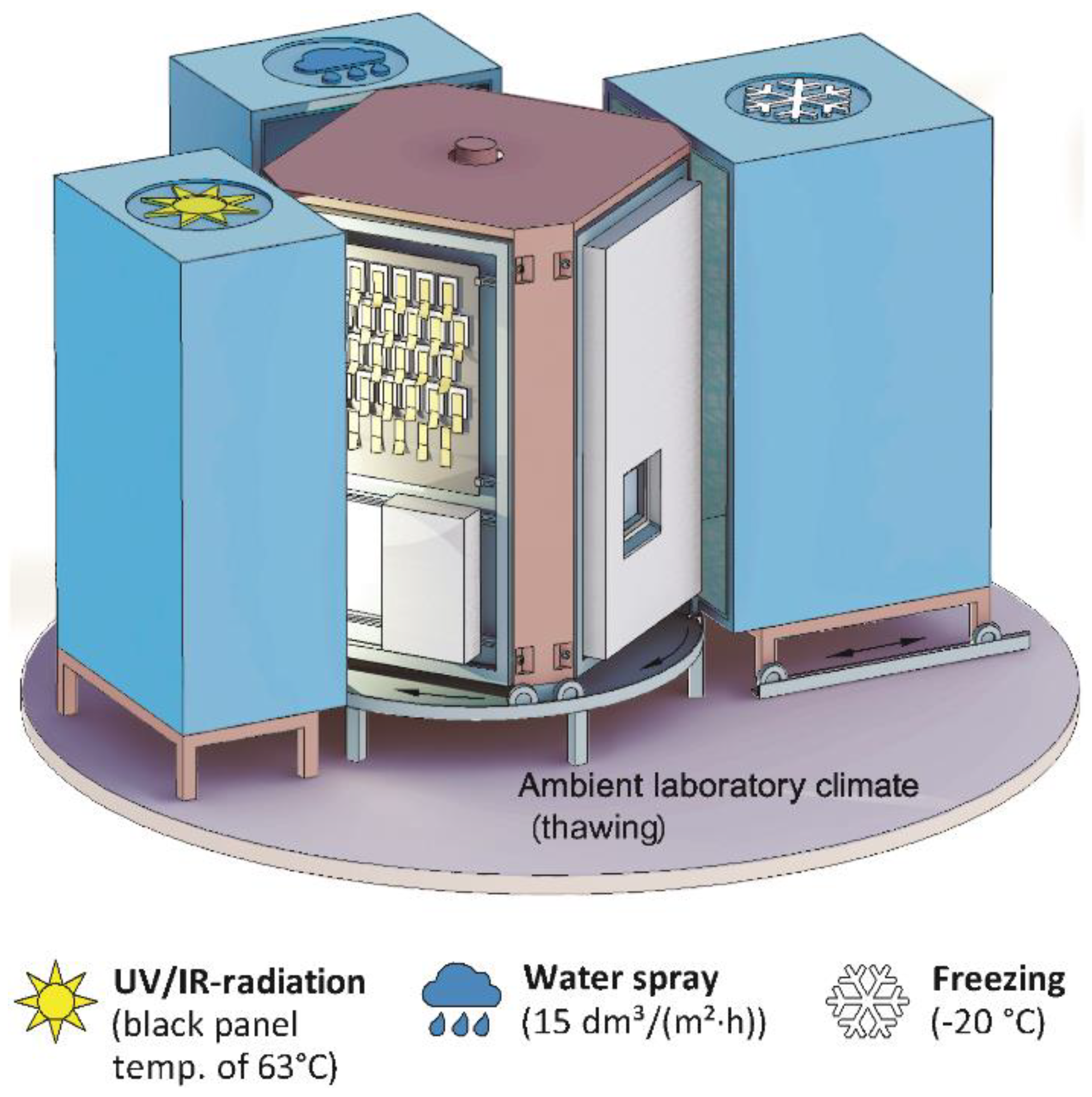
Figure 5.
Distribution of defect cases to external walls above ground depending on the type of cladding. Taken from SINTEF Building Defect Archive (period 1993–2002) [20].
Figure 5.
Distribution of defect cases to external walls above ground depending on the type of cladding. Taken from SINTEF Building Defect Archive (period 1993–2002) [20].

Figure 6.
Ranking of the most frequent building-defect causes for ETICS in SINTEF Building Defect Archive (period 1993–2017). See description of defect causes A–O in the text.
Figure 6.
Ranking of the most frequent building-defect causes for ETICS in SINTEF Building Defect Archive (period 1993–2017). See description of defect causes A–O in the text.

Figure 7.
Recommended installation of window in a brick or concrete wall with ETICS. The flashing variant is adapted to the render system in question and is most applicable for render mortars based on organic binding agents (plastic).
Figure 7.
Recommended installation of window in a brick or concrete wall with ETICS. The flashing variant is adapted to the render system in question and is most applicable for render mortars based on organic binding agents (plastic).

Figure 8.
Example of a moisture-resistant wall finishing against a balcony.

Figure 9.
Example of a moisture resistant transition between a façade system with ETICS and a brick veneer wall.
Figure 9.
Example of a moisture resistant transition between a façade system with ETICS and a brick veneer wall.

Figure 10.
Example showing how effective corner reinforcement can be achieved.


© 2018 by the authors. Licensee MDPI, Basel, Switzerland. This article is an open access article distributed under the terms and conditions of the Creative Commons Attribution (CC BY) license (http://creativecommons.org/licenses/by/4.0/).
Share and Cite
MDPI and ACS Style
Kvande, T.; Bakken, N.; Bergheim, E.; Thue, J.V. Durability of ETICS with Rendering in Norway—Experimental and Field Investigations. Buildings 2018, 8, 93. https://doi.org/10.3390/buildings8070093
AMA Style
Kvande T, Bakken N, Bergheim E, Thue JV. Durability of ETICS with Rendering in Norway—Experimental and Field Investigations. Buildings. 2018; 8(7):93. https://doi.org/10.3390/buildings8070093
Chicago/Turabian StyleKvande, Tore, Noralf Bakken, Einar Bergheim, and Jan Vincent Thue. 2018. "Durability of ETICS with Rendering in Norway—Experimental and Field Investigations" Buildings 8, no. 7: 93. https://doi.org/10.3390/buildings8070093
Note that from the first issue of 2016, this journal uses article numbers instead of page numbers. See further details here.