Advances in Structural Systems for Tall Buildings: Emerging Developments for Contemporary Urban Giants

1
School of Architecture, University of Illinois at Urbana-Champaign, Champaign, IL 61820, USA
2
School of Architecture, Yale University, New Haven, CT 06511, USA
*
Author to whom correspondence should be addressed.
Buildings 2018, 8(8), 104; https://doi.org/10.3390/buildings8080104
Submission received: 2 July 2018
/
Revised: 27 July 2018
/
Accepted: 30 July 2018
/
Published: 10 August 2018
(This article belongs to the Special Issue Sustainable Vertical Urbanism)
Abstract
:New developments of tall buildings of ever-growing heights have been continuously taking place worldwide. Consequently, many innovations in structural systems have emerged. This paper presents a retrospective survey of the main structural systems for tall buildings with emphasis on the advancements of recent, emerging, and potentially emerging systems. A structural systems chart that was previously developed by the authors has been updated in this paper to recognize, categorize and add the more recent structural systems. Recent trends of tubular structural systems in modified forms including the braced megatubes and diagrids are presented. Core-outrigger structural systems are discussed with emphasis on their adaptability. The potential of employing superframes for stand-alone and conjoined megatall buildings is predicted. As a means to solve today’s various project-specific complex design requirements, different mixed structural systems for supertall and megatall buildings are presented. This paper also discusses the widespread application of composite structural systems and recent trends of concrete cores for contemporary tall buildings. Finally, the future of tall buildings is predicted as the race for height continues.
Keywords:
tall buildings; supertalls; megatalls; structural systems charts; interior structures; exterior structures; core-outriggers; tubular systems; braced megatubes; diagrids; superframes; conjoined towers; buttressed cores; combined and mixed systems; composite structures; concrete cores; height races1. Introduction
Following the catastrophic event of 11 September 2001 that brought down the World Trade Center buildings in New York, naysayers hastily predicted that it marked the end of future skyscraper construction. Engineers and architects who knew the history of tall buildings in cities, however, knew that these urban edifices did not surface fortuitously, but rather were essential to address the problems of increased human habitation as the world population continued to grow and people were moving from rural areas to cities [1]. During the presentations of papers on tall buildings in different settings, both authors faced critics of tall buildings and tried to get across to them the logic behind the unrelenting development of tall buildings in the absence of alternate viable solutions to the problem of increasing high density in cities. Admittedly, tall buildings have a few shortcomings. Yet, there is no reason urban sprawl should be created or encouraged horizontally with its many associated drawbacks when the vast and empty sky is available to generate a vertical scale of cities [2]. Many tall buildings including supertall (greater than 300 m) and megatall (greater than 600 m) have been built in the first two decades of the 21st century. According to the Council on Tall Buildings and Urban Habitat (CTBUH) and the 25 December 2017/1 January 2018 issue of Time magazine, 144 skyscrapers in cities measuring 200 m and over were built in 2017, more than any other year in history. Tall building construction has been a global phenomenon for the last few decades and the race for height continues.
An earlier paper by the authors reviewed the structural systems for tall buildings and developed a height-based structural systems chart under the broad classification of interior and exterior systems [3]. Many innovative structural systems have emerged since then. Keeping this in mind, the present paper updates the foregoing structural systems chart and also provides a retrospective survey of main structural systems for tall buildings including the recent ones with special emphasis on the emerging systems. To fully understand the progression of these systems, it is important to trace back to their origin. Structural systems for tall buildings have undergone intense transformations in the second half of the 20th century. These changes in the structural form and organization of tall buildings were necessitated as well as facilitated by the incipient architectural trends in design, economic demands, and technological developments in the realms of rational structural analysis and design made possible by the advent of high-speed digital computers. As discussed later, the development of a variety of efficient structural systems for tall and supertall buildings was possible because of a groundbreaking principle, called the “premium for height”, first envisioned by Fazlur Khan [4]. With his height-based structural systems charts that included his signature tubular system, he instigated a departure from the conventional rigid frame system suited to rectilinear, repetitious, prismatic vertical configurations and flat “topless” roofs defining the International Style and modernist architecture prevalent until the advent of postmodernism. During this era of modernism, the façade was generally designed with a constant or smoothly varying profile following rigorous discipline that exhibited austere structural regimentation. Beginning in the early 1980s, these forms were largely replaced by the highly articulated modulations of the building’s façade and the top, characteristic of postmodern, regional, and deconstructive expressions, which eventually morphed into the pluralistic styles and iconic features in the architectural expression [5]. This new generation of tall buildings broke the monotony of the box-type tower form and led to novel high-rise expressions. Nevertheless, beginning in the 1960s, different types of forms and structural systems cropped up such as: tubes, diagrids, superframes, core-outrigger systems, mixed steel-concrete systems and a few other improvements since the gradual demise of the conventional rigid frames when the principle called the “premium for height” was conceived.
2. Premium for Height and Other Considerations
Interestingly, for structures, the scale is really an age-old concept since the days of Aristotle, who thought of it and emphasized that beauty of an object is a matter of size, proportion, and order. Galileo Galilei proclaimed that the size of organism or artifact has a decisive influence on its structure and function and validated his theory by accurate observations on both animate and inanimate structures and forms [6]. It can be inferred that as any structural system is scaled up, the load effect will eventually be greater than the strength of the structure. Architects and structural engineers know that for increasing horizontal spans different structural elements are required for efficiency in the order of beams, trusses, arches, cables, etc. Khan applied this reasoning to vertical structures and asserted that for increasing heights of structures different structural systems are necessary. This realization stemmed from the fact that, as the buildings become taller, a premium for height due to lateral loads caused by lateral wind loads has to be paid, and the demand on the structural system dramatically increases.
Based on his investigations, Khan argued that as the height increases beyond 10 stories, the lateral sway starts controlling the design and stiffness rather than strength starts becoming the dominant factor, and the premium for height increases exponentially with the number of stories. What creates this condition is that the total lateral deflection due to shear racking and cantilever action due to lateral loads is greatly magnified with height and hence the stiffness demand of the building increases dramatically. The straight line in Figure 1 represents the steel consumption with regard to height if, hypothetically speaking, the building is not subjected to lateral loads at all, i.e., gravity loads alone are carried by the building. For practical design, the goal is to minimize the consumption of structural material by reducing the shaded area with the selection of a more appropriate structural system. Such a system can be accomplished by recognizing that the better carrying capacity of a building comes from the synergistic arrangement of its structural members, i.e., by providing enhanced strength and stiffness by design through more effectively counteracting the internal forces and deformations generated in the members caused by external loads. This leads to the notion of variability of structural systems to meet the requirements of different loadings and the building’s dimensional parameters.
The lateral load effect due to wind increases with increasing height for which the pressure on the windward side of the building increases upward nonlinearly following power law thereby making the premium for height intensified. Although the second-order effect of wind loading was not explicitly presented by Khan in describing the basic premise of the premium for height, it is important to note that it makes matters worse as lateral sway becomes more pronounced for a tall building, which is relatively much slenderer with a higher height-to-width aspect ratio than a typical low-rise or mid-rise building, due to this phenomenon. The second-order effect is caused by the additional overturning effect as a result of the building’s vertical gravity loads acting on the progressively augmented deflected profile due to sway. Even in seismic zones, for very tall buildings that have low natural frequencies, lateral sways due to wind related to occupant comfort and avoidance of damage to nonstructural components rather than earthquake forces generally control the design. However, adequate ductility and energy-dissipation capacity of the building must be ensured for seismic loads by appropriate detailing of structural components and connections to ensure continuity and accommodate inelastic behavior at these locations where plastic hinges may form at the ultimate load level. As many supertall buildings have been built in major seismic zones in recent years, the consideration of earthquakes has become an important structural design criterion in addition to wind. Nonetheless, the primary focus in structural design of lateral load-resisting systems for supertall and megatall buildings often remains on wind.
Generally, a dynamic analysis of tall and slender buildings for wind is warranted to determine the lateral acceleration of the upper floors so that occupant comfort is assured against excessive building vibration by managing the acceleration either by changing the building’s mass and stiffness parameters, where possible, and/or by introducing auxiliary active or passive control systems. For supertall and megatall buildings, special consideration of vortex-shedding-induced across-wind response is necessary as it could cause disastrous resonance. Another practical way to control wind-induced responses of such buildings is through providing the building globally with non-prismatic forms to disrupt the organized vortex shedding over the building height and/or locally by creating special plan forms that are notched, chamfered, rounded, etc. in the corners and irregular exterior surfaces to reduce the aerodynamic effects [3,5,7,8,9].
3. Hierarchy of Structural Systems
Following the line of reasoning based on the premium for height concept as described above, Khan recognized that a hierarchy of structural systems could be categorized with respect to relative effectiveness in resisting lateral loads for buildings beyond the 20-to-30-story range that are suitable candidates for rigid frame system. For the first time, he classified structural systems for tall buildings relating to their heights with considerations for efficiency in the form of “Heights for Structural Systems” charts [10,11,12] as shown in Figure 2. He developed these charts for both steel and concrete. These charts were logically based on height, as tall buildings are identified by their distinctive and striking feature of height that also affects the building’s structural performance. He argued that the rigid frame that dominated tall building design and construction until then was not the only system fitting for tall buildings. He made the case that the structure could be treated in a comprehensive manner in which the three-dimensional building’s structural behavior could be rightly viewed in three dimensions as in a tubular system rather than as a series of planar systems in each principal direction of the building.
Before developing the structural systems chart, in 1961 Khan conceived the idea of the “hollow thin tube” and designed the 43-story DeWitt-Chestnut Apartments (now called the Plaza on Dewitt) using peripheral framed tube in Chicago, which was completed in 1966 [4]. Other variations of the tubular structure are tube-in-tube, braced tube, bundled tube, and partial tube in which the tube is placed as end channels with interior shear wall/shear truss. In addition, Khan and his associate first conceived and published a paper on the idea of shear wall-frame interaction in 1964 in which the previously held notion of shear walls and frames acting independently was dispelled [13]. As a result, these charts primarily included his own known devised systems which have been widely discussed in the literature [4,5,14,15,16,17]. These revolutionary charts opened up the possibilities of other viable structural systems for tall and supertall buildings. In the 1960s, the notion of aerodynamics, finite element analysis, computational fluid dynamics, etc. of the aircraft industry was still in an up-and-coming stage for tall buildings. Moreover, it was also the high point of modernism. As a result, the structural systems charts were conceived in terms of basic forms that were rectilinear in plan.
Since the first development of Khan’s charts in 1969 followed by his modification of the charts later in 1973 and 1974, some new structural systems for supertall buildings appeared on the scene and were applied in practice. However, no new classification of height-based structural systems was made for many years. It, therefore, became necessary to develop state-of-the-art charts. Keeping this in mind, the authors carried out research and published the results in the form of an expanded chart [3]. All structural systems in these charts were height-based and broadly classified into interior and exterior systems considering whether the lateral-load-resisting elements are located primarily in the interior or in the perimeter of the building. The present paper presents updated and expanded charts to reflect additional recent structural developments in tall buildings as shown in Figure 3a,b. Although buildings of greater height than those shown in the charts may be built, the purpose of the charts is to demonstrate efficient and feasible height limits of structural systems for tall buildings. The corresponding height-to-width aspect ratios may be up to, but not limited to, about 10, as they often vary widely depending on project-specific design conditions. These story heights are presumptive and should be taken as guidelines only as the actual height will be determined by the structural engineer considering many factors governing the design of a particular tall building.
Unlike Khan’s charts where steel and concrete structures are separately presented, these new charts include both steel and concrete, and composite structures within the context of exterior and interior structures. Tables accompanying the charts for different categories and subcategories of structural systems, giving the details of material and configuration, as well as their advantages and disadvantages are presented in Table 1 and Table 2. Examples of each category of structural systems are also included in the last column of these tables.
3.1. Narrative of Interior Structures
Studies on rigid frames and braced frames have widely been published including the earlier paper by the authors [3].
The staggered truss is added to the categories of the interior structures. The system was developed at Massachusetts Institute of Technology as a very efficient steel structural system for tall buildings in the mid-1960s, but not included in Khan’s and the previously developed chart of 2007 by the authors. The system is composed of story-deep trusses spanning full width of the building and typically placed at a regular interval on a given floor. These trusses are arranged in a staggered fashion on the vertically adjacent floors and supported by columns on the perimeter. Typically, no trusses are placed on the ground floor. The unique compositional characteristics of the staggered truss system impose functional limitations to the building. The most appropriate functions the system can accommodate are those requiring regularly placed walls such as hotels. The system is efficient up to about 40 stories and more appropriate for buildings with rectangular floor plans.
Concrete shear wall as a stand-alone lateral load-resisting system was excluded from the present chart as this system has become uncommon for tall buildings once the mechanics of shear wall-frame interaction included in Figure 3a was formulated to exploit their increased lateral-load resistance. Occasionally, however, concrete shear walls are solely used as lateral load resisting systems. In concrete core-suspended buildings, such as the 28-story tall Aviva Tower of 1969 in London, floors are hung from the core, and, therefore, both gravity and lateral loads are carried only by the concrete core. These structures can be efficiently used up to about 40 stories, comparable to the recommended height limit of the concrete shear wall system with hinged steel frames in the chart as the lateral participation of the hinged frames is negligible in the system. Similarly, concrete cores can be used solely to carry both gravity and lateral loads by cantilevering floors from the core as is the case with the 52-story tall Singapore Treasury Building of 1986 in Singapore.
In Khan’s steel system charts, the belt truss system which implies core-outriggers with belt trusses is recommended for tall buildings up to only about 60 stories as the outriggers stretching from the core to the megacolumns as an alternate to belt trusses were not yet fully investigated and applied since their use in the reinforced concrete Place Victoria building in Montreal in 1964. In the authors’ chart in their earlier publication they recommended the outrigger system for tall buildings up to 150 stories considering the advent of megacolumns for exceptionally tall buildings in the perimeter structure [3]. The present chart adds the core-outriggers with megacolumns as a separate subcategory. The efficiency and economy of the system can be augmented by using core-outriggers with megacolumns employing composite construction mixing both steel and concrete. Moreover, the application of structural optimization procedure in terms of the number and location of outriggers, etc., using currently available specialized engineering software further increases the system’s efficiency [18]. Nonetheless, the structural efficiency of the core-outrigger system as an interior structure cannot exceed that of some of the most efficient exterior structures such as those with large perimeter diagonals [19]. However, another reason the core-outrigger system is suggested for tall buildings up to about 150 stories, which is in fact taller than the suggested story heights for many exterior systems, and actually used for many supertall buildings today, is that it is architecturally more flexible for façade design.
Buttressed core is added as a new type in the interior system. Though this system is essentially an extension of the concrete shear wall core system, its significance as structural systems for some of today’s tallest buildings in the world is recognized as a new system in the chart. For extremely tall buildings, structural systems cannot be configured independently without considering building forms. To maintain structural efficiency, it is important to keep reasonable aspect ratios for extremely tall buildings such as those whose heights are close to or over 1 km. Therefore, the width of the building has to become larger as it becomes taller and this condition makes very deep interior space uncomfortable for users, especially due to the lack of natural daylight away from the perimeter, when common squarish plans are used. To resolve this issue, building plans can be configured to have multiple wing spaces of reasonable spatial depths branched from the central area which has a central structural core that extends as shear walls into the wing spaces to better structure the overall plan configuration. Tall buildings of this configuration typically have three wings copying a tripod representing the basic stable system in combination with tapered forms for better structural and architectural performance. Concrete core shear walls extended to the wing spaces of the building are further stiffened by additional shear walls perpendicular to them as in the Burj Khalifa and Jeddah Tower or outrigger systems as in the Wuhan Greenland Center [20,21]. Though these architecture-integrated structural configurations are very efficient for exceedingly tall buildings, flexibility in space use is limited to a large degree due to the specific forms required.
Different from all the other system diagrams, the buttressed core system is applied with a Y-shaped or triangular plan with three wings. In fact, similar forms are one of the recognizable trends in today’s supertall building design. Among the 50 tallest buildings in the world including those under construction such as the Jeddah Tower, eight of them (16%) have triangular form plans. All of these eight buildings are over 400 m tall and are already built or under construction since 2010.
3.2. Narrative of Exterior Structures
A tubular system employs a perimeter structural configuration responding to lateral loads as a three-dimensional frame that acts as a hollow tube cantilevering out from the ground. In a framed tube the perimeter columns are very closely spaced and connected by deep spandrels at floor levels. It is a powerful structural system as it is highly efficient in maximizing the overturning capacity of the building and allows flexibility in interior planning.
Braced tube systems in the authors’ previous chart of 2007 are further categorized into conventional braced tubes, braced tubes without interior columns and braced megatubes. Braced tubes without interior columns are an extension of the conventional braced tube that has interior columns. While this system exists in both the original Khan’s and the revised charts in this paper, it has not been applied yet to any major tall building. In this system, the perimeter braced tube carries not only lateral but also the entire gravity loads, which apply compression on the windward side thereby reducing uplift forces and reduce the overturning effect on the building. Consequently, the system can be taller than a regular braced tube building with interior columns, and recommended up to about 150 stories. However, the system requires very long span floor structures which must span the entire building width. This may be very challenging for practical application. In addition, while the system is suitable for supertall buildings, it precludes the provision for a second line of defense against any structural danger triggered by the damage in the perimeter braced tube caused by deliberate or accidental external impact.
Braced megatubes are primarily composed of corner megacolumns and large diagonal braces between them. This system is more efficient than the traditional braced tubes and consequently recommended for taller buildings up to about 170 stories because it provides substantially greater bending rigidity against overturning moments. Though the enhanced structural efficiency of the braced megatubes was already conceived by Khan decades ago [22], their actual applications are only to recent tall buildings of extreme heights.
For very tall structures, a single framed tube is not adequate since the width of the building should be large to maintain a reasonable height-to-width aspect ratio. The wider the structure becomes, its shear lag property increases, and consequently the efficiency of the system is considerably diminished. This problem can be resolved by bundling a few single tubes that was conceived as an improvisation of the single tube for the design of Sears Tower (now called Willis Tower) of 1974 in Chicago and the new system came to be known as a bundled tube system.
Diagrids, which have their origin in Sukhov Tower of 1922 in Moscow and IBM Building (now called United Steelworkers Building) of 1963 in Pittsburgh, PA, gained popularity during the last two decades [23]. Performance characteristics of diagrids are similar to those of the braced tubes although they are visually two different systems. Diagrids are categorized into two different types of uniform and varying-angle diagrids. A uniform-angle diagrid structure designed with an optimal angle is efficient for tall buildings up to about 110 stories with their height-to-width aspect ratio of about 7, while varying angle diagrids with diagonals placed at gradually steeper angles toward the base could be more efficient than uniform angle diagrids for even taller buildings with their aspect ratios greater than about 7 and suitable for tall buildings up to about 130 stories [24].
While the tube-in-tube system is shown only for reinforced concrete structures in original Khan’s charts, many different combinations are possible with different tubular structures employing different structural materials. Framed tube, braced tube and diagrids can be used to constitute exterior tubes and they, in addition to the reinforced concrete core, can also be used for interior tubes. In the expanded charts, the tube-in-tube system incorporating the perimeter steel framed tube and concrete core represents many different possible combinations. The tube-in-tube system is a combination of the interior and exterior structures, though the structural efficiency of the exterior tube is typically much greater, especially when it is either braced tube or diagrids, than that of the interior tube. Therefore, this type of structural system can be categorized as an exterior structure as shown in the expanded chart.
In space trusses the principal load-carrying system comprises three-dimensional trussed structures. A well-known example is Hong Kong’s 72-story Bank of China Building in which both gravity and lateral loads flow through the trusses and are transferred to the composite corner columns of substantial sizes.
Superframes are typically large interconnected boxes, each of the boxes several stories high, set over one another. Each box comprises large beams and columns that are internally strengthened with lattices or trusswork. Superframes can have different forms. The superframe in the authors’ previous chart of 2007 is further categorized in this paper into stand-alone superframe and superframed conjoined tower structure which is a conceptual expansion and modification of stand-alone superframe. Conjoined supertall towers are a relatively new architectural phenomenon [25]. When the superframe idea is applied to conjoined towers composed of multiple towers, their heights can be increased very efficiently by structurally connecting the towers. In this way, structural depths of the conjoined towers are not defined by the depths of the individual towers but can be defined by the depths of the group of the conjoined buildings. This architecture-integrated structural concept can be suggested for conjoined towers up to about 250 stories and even more. Such systems can be placed in several city blocks interconnected by bridges thereby creating a lively self-contained vertical city-in-a-city for work, commerce, living, and recreation.
Relationship of structural systems with the aesthetic expression of tall buildings is of crucial importance. This is where the architect and the structural engineer need collaborative effort. Among other attributes, a tall building’s aesthetic quality is a critical one about how the tall building declares itself by demonstrating how it was built, how it remains stable, how it functions, how it reflects culture and tradition, and how it responds to urban and even global contexts. The building’s appearance is influenced by the architect’s selection of the building form and façade, whether it will be more of a decorative covering over the architecture-driven form or the honest expression of the structure showing its logical form and load path or will include some deconstructive or rare high-tech features. With exterior systems the structure can be disclosed on the façade in a logical manner in the spirit of an artist; structural expression then becomes the architectural expression of the building. With interior systems, this notion of structural expressionism takes a back seat, but present-day architects generally prefer this approach as it provides them more freedom to articulate the unobstructed façade in a way they choose.
4. Extreme Engineering of Structural Systems
Buildings of extreme height demand extreme engineering measures. Extreme engineering for tall buildings is characterized by the technical challenges related to constructing megascale and highly innovative skyscrapers that aspire to reach for the sky defying the fierce natural forces of gravity, wind and earthquake. To meet the demands imposed by their extreme height as well as the challenges associated with excessive gravity and lateral loads applied on them, creativity in their structural design becomes a necessity. Many of the structural systems of contemporary supertalls and megatalls having their origin in basic structural systems devised earlier are therefore modified with improvements and refinements incorporating the latest design and technological advancements. In the following, significant recent trends of some of these structural systems are discussed with example buildings.
4.1. Resurgence of Tubular Structures
Major tubular or modified tubular buildings like the Sears Tower (now called Willis Tower) and the John Hancock Center (now called 875 North Michigan Avenue) in Chicago and demolished World Trade Center in New York were built prior to 1980s; they all have rectilinear plans [26]. During this time, tall building architecture began featuring nonrectangular plans, multiple stepbacks, distinctive tops, tall and open entry lobbies, and underground parking. These features often place a cost premium on closely spaced columns employed in tubular systems or become incompatible with the tubular concept. As a result, structural engineers began to experiment with new ideas to devise other solutions for structural schemes of tall buildings. Nonetheless, the tubular systems have yet continued to evolve to better meet today’s diverse structural and architectural requirements. This section presents the most recent applications of tubular structures which evolved after the high point of tubular tall and supertall buildings in the late 1960s and 1970s. The original development of the various tubular systems by Khan has lately reopened the era of supertall buildings with greater structural efficiency. Other structural systems for supertall and megatall buildings of today and those poised for the future are also presented in the subsequent sections.
Among the framed, braced and bundled tube systems, the braced tube system with large perimeter diagonals is the most efficient one in general [27]. As envisioned by Fazlur Khan as “the ultimate possible improvement of the structural efficiency” [22], and proposed also by William LeMessurier for his theoretical study of the 207-story tall Erewhon Center [28], the best column arrangement in a square floor plan of a tall building is four large corner columns with X bracings between two corner columns on the same side to provide maximum lateral stiffness. Compared to the typical braced tube composed of equally spaced multiple columns on each façade plane, this four-corner megacolumn arrangement provides about 25% greater lateral stiffness for a 100-story building with an aspect ratio of about 7 [19]. However, one important issue of this case with only corner megacolumns on the perimeter is that it requires a more sophisticated system to carry gravity loads which must be carried also by the four megacolumns.
This idea of a modified braced tube with corner megacolumns and a reasonably good solution for transferring gravity loads has been employed for recent supertall buildings and they are classified as braced megatubes in this paper. In the 597-m tall 128-story Goldin Finance 117 building currently under construction in Tianjin, four corner megacolumns in conjunction with large perimeter braces carry lateral loads very efficiently (Figure 4). The cross-sectional area of the hexagonal composite megacolumns varies from enormously large 45 m2 at the base to 5.4 m2 at the top. Large X-braces composed of welded steel box sections are placed between the megacolumns over the entire building height to form a braced megatube. The 34 m × 32 m composite core also participates in providing lateral stiffness, resulting in a tube-in-tube system [29]. As is common in the tube-in-tube system, the exterior braced megatube provides greater lateral stiffness in this building. In terms of carrying gravity loads, there are additional small gravity columns between the corner megacolumns. The gravity loads in these gravity columns are transferred to the megacolumns through the belt trusses installed between the megacolumns at every about 15 stories in relation to the module height of the perimeter X bracings. The connections between the gravity columns and transfer belt trusses are made in such a way that the progressive collapse can be prevented when some of the gravity columns within the module are seriously damaged. The gravity columns between the transfer belt trusses are provided with vertically slotted connections with the top trusses. Therefore, these columns supported by the bottom trusses carry the floor loads entirely by compression in normal cases, but some of the columns toward the top trusses change to tension columns when any column failure occurs within the module.
While the arrangement of corner megacolumns establishes one of the most efficient lateral load- resisting systems, it is obstructive for viewing, particularly impacting the coveted interior corner spaces of the building. In fact, this was a concern when the Goldin Finance 117 was engineered. In the 528-m tall 108-story Citic Tower (formerly known as China Zun Tower), also currently under construction in Beijing, a very similar structural concept was used [30,31]. However, the corner megacolumns of the Citic Tower are split into two following the rounded square-shaped floor plans, to provide column-free corner space. Though this configuration with paired megacolumns around the corners does not provide the same level of stiffness provided by single corner megacolumns when the same amounts of structural materials are used, it produces more desirable architectural result. The configuration of the gravity columns and transfer belt trusses in the Citic Tower is very similar to that in the Goldin Finance 117.
Though framed tubes developed in the 1960s were used as a very efficient structural system for many tall buildings of the 1970s and 1980s, they were not widely used during the following decades because of the closely spaced perimeter columns interfering with the façade design significantly. However, framed tubes are employed again for some of the recent supertall residential towers, such as the 426-m tall 432 Park Avenue in New York (Figure 5) and 445-m tall Marina 106 in Dubai [32]. While tall buildings were predominantly commercial office towers until even the late 20th century, beginning from the 21st century the number of residential towers has been greatly increasing. For residential tall buildings whose floors are typically composed of many separate rooms, smaller perimeter openings of the framed tube system could be well integrated with the floor plans and corresponding façade design.
In fact, the abovementioned revival of framed tubes in conjunction with ever-increasing residential supertall buildings in recent years typically produces tube-in-tube structures because these buildings usually have reinforced concrete cores which structurally perform as inner tubes. If well integrated with residential plan layouts composed of multiple small spaces, the tube-in-tube structural system could even further be developed into more efficient bundled tubes. The bundled tube system used for the Sears Tower is a very efficient structural system for supertall buildings. However, the bundled tube system ends up with interior columns which diminish flexibility in interior space layouts and consequently the system is not that desirable for most of today’s office spaces. In residential towers, however, the bundled tube system with interior columns and/or walls could potentially be articulated and well integrated with various types of residential function.
The tube system gradually went out of favor from around the advent of postmodern style of tall buildings in the early 1980s. Khan lamented just before his death in a paper that was posthumously published, but predicted the return of this and other systems based on structural logic [33]. It has lately made new inroads validating Khan’s prediction. While many other systems are also widely used for tall buildings today, the tubular system still provides one of the most efficient structural concepts with its powerful structural rationale.
4.2. Adaptability of Core-Outrigger Structures
The core-outrigger system, being an interior structure, has been adaptable to a great range of heights. The earliest known pioneering tall building in reinforced concrete that was structured with the core-outrigger system was by Pierre Luigi Nervi and Luigi Moretti [4]. It is the 190-m tall 47-story Place Victoria Building (now called the Stock Exchange Building) of 1964 in Montreal. The core-outrigger system was later employed by Fazlur Khan in the structural system of the 41-story BHP House (now called 140 William Street) of 1972 in Melbourne and the 42-story First Wisconsin Center (now called U.S. Bank Center) of 1973 in Milwaukee [34]. Khan used belt trusses connected to the core with outriggers, although megacolumns in the perimeter can also be used to connect the outriggers to the core as was done in the Place Victoria Building. He included the belt truss system that implied a core-outrigger concept in his chart with a proposed height limit of 60 stories but did not include core-outriggers with megacolumns (Figure 2).
The main structural advantages of core-outrigger system are that the perimeter framing system may consist of simple beam-column connections without the need for expensive rigid-frame-type framing joints [35]. It is also amenable to steel, concrete and composite (i.e., mixed steel-concrete) construction, which is so pervasive for contemporary tall, supertall, and megatall buildings. When provided with belt trusses, differential column shortening is reduced by these horizontal trusses. Its disadvantages are that the outriggers interface with occupiable or rental space and cause some disruption in the erection process. Usually, the outrigger floors are used for mechanical levels or refuge floors and careful structural planning is carried out by developing clear erection guidelines. It, however, gives the architect the flexibility of selecting exterior column spacing thereby allowing for a relatively unhindered façade and varied aesthetic patterns. This system has lately been very popular and its use is widespread. The clear reasons for this are that the architects can experiment with various options for the façade, as the outriggers can be accommodated in the buildings in varied forms such as trusses, Vierendeels, walls, virtual outriggers, etc. and fashions in terms of layout, spacing, relationship with the core, etc.
The tallest building structurally designed primarily with the core-outrigger system is the 729-m tall 137-story Suzhou Zhongnan Center in Suzhou, China. The project is currently on hold, but when completed it will become the tallest building in the country and third tallest building in the world only after the Jeddah Tower currently under construction and Burj Khalifa [36]. The square-shaped composite core at lower levels with its side dimension of 35 m is designed to carry most of the lateral shear forces and partial overturning moments for this vertically stretched slender pyramidal shape building. Five sets of two-story tall steel outrigger trusses are extended from the core and connected to the eight concrete megacolumns, which carry most of the overturning moments. The megacolumns on each side and additional four large corner columns are connected by two-story tall double layer belt trusses at the five outrigger levels, which are integrated with mechanical and refuge floors, and four other levels mostly between the outrigger levels to form an exterior mega-frame altogether, which provides supplementary lateral stiffness. To control wind-induced acceleration, this building will also have a 750-ton tuned mass damper and 600-ton tuned sloshing damper integrated with its fire water tank near the top [37,38]. Viscous dampers are also planned to be installed in this building to dissipate seismic energy during earthquakes.
While various damping mechanisms can be incorporated in tall buildings structured with core-outrigger systems, damping mechanisms have also been directly integrated with the outriggers in some of the recent supertall buildings [39,40]. In the 393-m tall 67-story China Resources Headquarters which is originally designed with reinforced concrete core and perimeter steel framed tube, it was found that the building needs either stiffer primary structure or supplementary damping during the construction. Since it was very difficult to stiffen the building under construction, a total of eight outriggers were placed between levels 47 and 49 [41]. Customized viscous dampers are installed in the connections between the tips of the outrigger and perimeter columns in a vertical direction so the wind-induced vibrations and accelerations can be significantly reduced to acceptable levels (Figure 6).
The 355-m tall 79-story Raffles City Chongqin T3N and T4N in Chongqin, China are very slender buildings currently under construction in a high seismic region with their height-to-width aspect ratio of 9.4. The structural system for this building consists of concrete core-outriggers with steel corner megacolumns and secondary frames between them. To effectively carry both the wind and seismic loads, composite outriggers are used at four levels in this building. Concrete outriggers are extended out from the concrete core to diagonally connect them to the steel corner megacolumns. There are steel plate shear links where the concrete outriggers and steel megacolumns are connected [42]. During normal wind and low seismic activities, the composite joined outrigger system provides the required stiffness to carry the applied loads. In the events of moderate or severe earthquakes, however, these shear links act as fuses dissipating the seismic energy thereby saving other structural components. Once the earthquake is over, any damaged shear links can be replaced. Another example with a similar design approach in a high seismic region can be found in the proposed 638-m tall 113-story Signature Tower in Jakarta. The structural configuration of the building originally proposed was very similar to that of the previously discussed Suzhou Zhongnan Center with steel outrigger trusses. As a design alternative, however, concrete outrigger walls with viscoelastic coupling dampers (VCDs) between the outriggers and megacolumns are proposed for enhanced seismic performance [43,44]. The steel connecting elements of the VCDs act as fuses in this case. VCDs are also proposed in the coupled concrete core walls of this building in place of the conventional diagonally reinforced concrete coupling beams. A similar design principle was used for the 335-m 73-story Wilshire Grand Center in Los Angles, another supertall building in a high seismic zone. Instead of steel-plate fuse links or VCDs, buckling restrained braces were used for diagonal members of the steel outrigger trusses in this building [45]. Buckling-restrained braces are designed to remain elastic under service loads and yield to absorb seismic energy during severe earthquakes.
To satisfy both wind and seismic design requirements, the core-outrigger system is also used as a main component of dual systems as in the case with the 508-m tall 101-story Taipei 101 in Taiwan well known for both winds and earthquakes. The building was designed based on the stiffness requirements against winds first and the design was refined for seismic ductility and strength [46]. Eventually, a project-specific dual system approach was developed. The primary system is the stiff braced-core supported outrigger system. Within and adjacent to the stiff outrigger system, steel girders including some of the dog bone sections were fully moment-connected to the columns to develop special moment frame action as the secondary system if needed in a major seismic event. For these special moment-resisting frames within the core, some of the lateral bracings were omitted.
Another variation in the core-outrigger system is the so-called “virtual outrigger”, which overcomes the conventional system’s disadvantageous construction delay at outrigger levels [47]. The term was first coined by Nair [48]. This system works with belt trusses or belt walls connected to the core through stiff diaphragm floor slabs with no conventional outrigger elements [49]. Early examples include the never-completed 77-story Plaza Rakyat Office Tower in Kuala Lumpur and the Tower Palace Three of 2004 in Seoul. The Tower Palace was originally designed as a 93-story building with a conventional core-outrigger system. However, the building was eventually reduced to a 73-story tower and the decision was made to remove outrigger walls and only retain belt walls. By doing so, the desired structural performance was met, construction was expedited, and no interior space was occupied by outrigger walls. More recent examples designed with the virtual outrigger concept include the 279-m tall 69-story Tore KOI of 2017 in San Pedro Garza García in Mexico. Since the virtual outrigger system in this building engages the perimeter columns with only belt walls through the floor slabs at the top and bottom of the belt structures without outriggers, these slabs were designed as thicker and stiffer slabs than those on typical floors [49]. Nonetheless, the conventional outrigger system with outrigger trusses or outrigger walls provides superior structural performance than the virtual outriggers. With their advantageous aspects over the conventional outriggers, however, the number of virtual outriggers can be more easily increased if desired to enhance their structural performances [47].
There is also a potential advantageous use of core-outriggers for tall buildings in relation to contemporary architectural design trends including the current trend of complex-shaped tall buildings, including tilted ones such as the proposed Signature Towers in Dubai by the late architect Zaha Hadid. It is really difficult, if not impossible, to find any other structural systems which can provide greater lateral stiffness in tilted tall buildings compared to the conventional vertical ones other than the core-outrigger system (Figure 7). When appropriately designed and employed, lateral stiffness of the core-outrigger system can be greater in tilted tall buildings than in an equivalent straight tower because of the triangulation of the major system components, i.e., vertical core, horizontal outrigger trusses and tilted megacolumns [50,51]. As the number of complex-shaped tall buildings keeps increasing throughout the world in this age of pluralistic architectural style, it is important to find efficient structural solutions for these tall buildings.
While perimeter megacolumns of core-outrigger structures are typically not explicitly expressed on the building facades, those in the 206-m tall Pabellon M in Monterrey, Mexico, are exceptions. Unlike typical megacolumns placed behind the curtainwalls, the reinforced concrete megacolumns in the Pabellon M are placed in such a way that about 50% of each megacolumn is inside the glass curtainwall façade planes and another 50%, outside [52,53]. Therefore, the structural depth of the building against lateral loads becomes even greater and at the same time the exposed concrete-finished megacolumns perform as an important façade design component. While one of the main motivations of the widespread use of outrigger structures in recent years was their ability to hide the major lateral load resisting components on the building facades thereby wittingly or unwittingly inhibiting the building’s structural expression, the systems’ potential expressive power as an aesthetic feature has also been explored through some of the recent tall and supertall buildings.
4.3. Uniform-Angle vs. Varying-Angle Diagrids
The diagrid of the present time which has also gained acceptance is an exterior system with a large number of diagonal elements crisscrossing at nodes creating a lattice-like appearance in which the columns are eliminated. The close diagrid arrangement creates an in-plane stiff shell-like structural shear membrane in the perimeter. It was extensively studied and discussed from different perspectives [3,23,54,55,56]. Both gravity and lateral loads can be carried by the diagrid system. Although structural analysis could be readily done for these structures with many slanted members and more complicated nodes due to the availability of sophisticated analysis software, detailing and fabrication of the nodal connections initially posed a significant challenge for the structural engineers. This constraint has now been largely overcome. Some major advantages of this system are that it is well suited to recent complex-shaped tall buildings especially for freeform towers because the geometry of such towers can better be defined with triangular planes naturally produced by diagrids without distortions [57], and being an exterior system, it is also cost-effective. The main disadvantage is that, unlike the core-outrigger system, the diagonals could be obstructive on the façade, although their slenderness largely minimizes this problem. Aesthetically speaking, the diagonals create an identifiable landmark quality of the building against the backdrop of the sky.
Many diagrid buildings have been built throughout the world since the most expressive 46-story Hearst Tower of 2006 in New York. Vertical megacolumns and superdiagonals were used as the structural system of the building up to the ninth floor and its structural system changes to the diagrids from the 10th floor to the top. A diagrid angle of about 70 degrees was consistently used throughout the diagrid portion of the structure, and these uniform angle diagrids are boldly expressed on the building façade. The height-to-width aspect ratio of the Hearst Tower is about 5 and this diagrid angle is close to the optimal for diagrid tall buildings of this height and height-to-width aspect ratio range. The Hearst Tower worked as a prototype of many successors of uniform angle diagrids. The 439-m tall 103-story Guangzhou International Finance Center is the tallest diagrid structure at this time and it can be considered as a uniform angle diagrids though there are some slight angle changes over the height due to the gently tapered form of the building (Figure 8).
As a major tall building lateral load resisting system with large perimeter diagonals, the structural performance of the diagrids is similar to that of the braced tubes. Both the systems carry the lateral loads very efficiently by axial actions of their primary structural members. The main compositional difference is that the conventional braced tube is composed of vertical columns and diagonals while the diagrids are composed of only diagonals. Therefore, in the braced tubes, overturning moments and lateral shear forces are primarily carried by verticals and diagonals respectively, while the both as well as gravity loads are carried by only diagonals in diagrids. These compositional and corresponding structural characteristics can lead to system specific optimizations.
Like the braced tubes, if the diagrid tall buildings with a square or rectangular floor plan are designed with large corner vertical columns, the efficiency of the system could be further increased. However, this type of configuration obstructs the valuable corner views from the interior, and is not considered as a pure diagrids in this paper because the system with corner columns and diagonal grids between them can still be considered as a braced tube. Alternatively, the diagrid angles could gradually be steeper toward the corners to accomplish similar structural advantage [58]. The 312-m tall CITIC Financial Center Tower 1 which is under construction in Shenzhen at this time is in a sense an example. The diagonal grids placed at comparatively shallow varying angles between the steeper corner members were logically configured to efficiently carry the seismic loads toward the bottom and wind loads toward the top [59].
While the strategy of steeper diagrid angles toward the corners is structurally beneficial, steeper and consequently denser diagrids toward the corner may not always be welcomed architecturally. Alternatively, diagrids can be designed with logical angle variations along the height of the building for very tall and slender towers, resulting in valuable column-free corner spaces like the prototype diagrids of the Hearst Tower in New York. Simultaneously considering load carrying mechanisms of gravity, lateral shear forces and overturning moments, the best strategy is using gradually steeper diagrid angles toward the base of the building [24,60].
The unbuilt 555-m tall 112-story Lotte Super Tower project by SOM in Seoul is a good example of vertically varying angle diagrids (Figure 9). The aspect ratio of this building is about 8. If a constant diagrid angle is desired, a uniform angle a little steeper than 70 degrees should be used because this building is much taller and slenderer than the Hearst Tower. Instead of using a uniform angle, however, vertically varying angle diagrids were proposed in order to maximize the structural efficiency of the system. An angle of about 78 degrees was used in the lowest diagrid modules and that of about 60 degrees was used in the highest diagrid modules. The building form tapers and morphs from 70 m × 70 m square plane at the base to 39-m diameter circle at the top, which was determined from the wind engineering analysis as well as representing the form of an old Korean celestial observatory structure.
If desired, the horizontal and vertical angle variations can be combined to result in even more efficient diagrid designs. While more efficient structurally, an important consideration of employing the varying angle diagrids is that its construction may be more costly than uniform angle diagrids due to its geometric complexity.
Several other well-known diagrid tall buildings, such the 30 St. Mary Axe in London, Tornado Tower in Doha, Capital Gate Tower in Abu Dhabi, and D2 Tower in Courbevoie near Paris, are all built or proposed with steel diagrids. Diagrid structures could also be of concrete. However, examples are rare partly because of the expensive formworks and slow speed of construction. In addition, triangular truss-like diagrids, which theoretically allow pin-type nodal connections not uncommon in steel structures, are somehow conceptually incompatible with site-cast concrete structures of monolithic nature. Moreover, the diagonals are large in size in concrete construction making them obstructive. Nonetheless, with their more fluid architectural aesthetics, reinforced concrete diagrids are expressively used in the exoskeleton of the O-14 Building in Dubai [3]. Another rare example of concrete diagrid structure is the Doha Tower in Doha, in which more regular looking diagrids are hidden most of the time behind the mashrabiya-motivated dense metal grid facades [23]. Certainly, another material possibility is composite diagrids which are used in the tallest diagrid at this time, the Guangzhou International Finance Center [61]. Round-shaped hollow steel tube diagrid members are filled with concrete for greater strength and stiffness in this building.
4.4. Superframes Reaching for the Sky
A superframe system was originally conceived in 1953 by Myron Goldsmith for an 80-story office tower [6]. Swenson also studied superframes that included the “pylon superframe” [62,63]. A rudimentary form of superframe system with macro-structural floors (macrolosas) was employed by Papparoni and Holma for the 56-story office building Parque Central Towers in Caracas, Venezuela in 1973 [4,5].
Fazlur Khan extended the superframe concept to its logical limit by developing his advanced superframe structure in a different way and envisioned an “ultimate structure” for extremely tall buildings in which the exterior columns could be progressively shifted to the square or rectangular stepped superframe for a tapered structure and by creating four megacolumns in the corners interconnected by large diagonals and horizontal transfer trusses [14]. He extended the concept to a megatall tower embodying four such megacolumns to design the never-built Chicago World Trade Center in which a few superframes telescoped within each other [4,64]. He worked on a few iterations using greater heights but settled for a 168-story structure for the colossal tower. The corner megacolumns of this tower were composed of individual columns arranged in an L-shaped layout and connected by large K-braces over four stories at a time. Although not used much for contemporary tall buildings, the superframe as a viable structural system has many possibilities for future supertall and megatall buildings with square or rectangular plan.
When Khan’s superframe idea is extended to conjoined towers for future tall buildings, exceptionally tall buildings can be achieved with increased structural depth. Conjoined supertall buildings are a recently emerging tall building design strategy. Quite a few competition entries, such as those by Foster and Partners, Meier Eisenman Gwathmey Holl Team, and United Architects, for rebuilding the World Trade Center in New York after 9/11, employed this approach, though the winning entry did not [65,66]. In fact, the concept of conjoined towers dates back to the King’s Views of New York published by Moses King in the early 20th century [25]. The King’s Dream of New York in this publication shows New York skyscrapers connected by sky bridges. In 1930, Iakov Chernikov proposed a complex conglomeration of skyscrapers into an interconnected and integrated whole [2]. Such connectivity with bridge-like structures may have major structural advantages, as individual towers are braced by other towers, provided they are integrally connected [67]. Today, interconnected tall, supertall or even megatall buildings are no longer a dream and are within our reach and more of future buildings like these are likely to appear in major cities [2,25].
The 452-m tall 88-story Petronas Towers of 1998 in Kuala Lumpur and more recently completed 302-m tall 66-story Gate to the East of 2015 in Suzhou are conjoined twin supertall office towers. In the former, the twin towers are connected simply by a double story sky bridge around the mid-height, and in the latter, the two towers are structurally connected at the top. While the structural benefits of integrally connecting two or more supertall towers have not been fully exploited yet, in the Golden Eagle Tiandi Towers which are under construction in Nanjing, three supertall towers rising 368, 328 and 300 m are interconnected structurally with a six-story tall sky lobby at the level of approximately 200 m to enhance the structural potential of the conjoined towers. The individual towers are structured with core-outrigger systems with belt trusses. The connections between the towers are made at the outrigger/belt truss level using five-story tall trusses. These trusses are connected to the belt trusses of the individual buildings, and consequently all three buildings are structurally belted together. By this configuration, the lateral stiffness of the whole conjoined tower structures is much greater than that of the individual towers [68].
By extending Khan’s superframe concept more strategically and in an integrative way with other design aspects, structural potential of the conjoined towers can be further increased and extremely tall building complex can be designed in a very efficient way structurally. Basically, the concept of superframed conjoined tower structure is a modified and scaled up version of Khan’s superframe. Instead of the four corner megacolumns in Khan’s superframe, four braced-tube towers can be placed in the corners of the enormous superframe allowing it to reach a much greater dizzying height. The braced-tube towers can be connected by horizontal bands of braced tube structures of multiple story height, which become the connections between the towers housing potentially sky lobbies and public spaces of truly city-like conjoined megatowers. At the same time, these are what create the superframed conjoined towers which use the entire width of the tower complex as the structural depth instead of the width of the individual towers. Therefore, the stiffness of the horizontal connection braced tube structures is a very important structural design consideration of these towers.
Figure 10 shows a mile-high superframed conjoined tower design project by Chris Hyun at Yale School of Architecture under the guidance of the co-author for a site in Chicago. The project was proposed for the empty site in Chicago partly including the area once used for the never- completed Chicago Spire project by Santiago Calatrava. In this design project, four exceedingly tall buildings are interconnected with the structural concept of the superframe to create the mile-high conjoined towers. Being a short-term comprehensive design seminar project, its structural system was only conceptually developed and is now further being investigated.
Despite its characteristics much appropriate for extremely tall buildings, the architecture-integrated structural concept of superframed conjoined towers may not be easily employed for existing dense urban land because very large building sites are required for them. However, where appropriate, these towers may also be the solutions for the problem of dense urban environments, by way of creating 3D vertical cities in the sky.
4.5. Combined and Mixed Structural Systems
Combined systems are not new in the chronicle of structural systems for tall buildings. Traditional examples which existed from the original systems chart by Khan are shear wall (or shear truss)-frame interaction and tube-in-tube systems. The former, as a combined system of two interior structures, is readily classified as an interior system. The latter is a combination of interior (i.e., the inner tube) and exterior (i.e., the outer tube) systems and can be considered as an exterior system because the outer tube is usually the primary lateral-load resisting structure. Many other different possibilities of combination exist in terms of structural materials and component systems.
Different from the traditional combined systems, in some of the new supertall and megatall structures, major components of the combined lateral load-resisting systems are shared, resulting in mixed systems. Consequently, the shared components in such systems carry out dual functions to meet project-specific design requirements. These systems are often produced in recent tall buildings when the interior core-outrigger system and the exterior megatube are employed together with megacolumns that are shared by both systems. One of the earliest examples in this category is the 492-m tall 101-story Shanghai World Financial Center of 2008 in Shanghai (Figure 11). This building, originally designed as a 460-m tall, had been structured with a tube-in-tube system with the reinforced concrete core and steel framed tube system, and foundation piles had already been in place based on this design when its design was changed to a 492-m tall building with larger plan dimensions [69]. To accommodate these changes without reconstructing the existing foundation system, more efficient structural system had to be developed for not overloading the foundation. As a solution, the perimeter framed tube was changed to a more efficient braced megatube, and consequently, the thickness of the concrete core walls and hence the weight could be reduced. In addition, outrigger trusses were added that connected the core and corner megacolumns diagonally. As a result, an unprecedented mixed system was created by engaging the core-outrigger system and braced megatube with shared megacolumns which represent major components for both systems.
Since the construction of the Shanghai World Financial Center, some of the supertall and megatall buildings have employed a similar structural system. These buildings include the 599-m tall 115-story Ping An Financial Center of 2016 in Shenzhen (Figure 12) and the 644-m tall 118-story Merdeka PNB118 which is currently under construction in Kuala Lumpur [70]. The performance of this type of mixed system composed of the two major structural systems is greatly influenced by stiffness distribution between them. It could be designed primarily as an interior core-outrigger system structure with additional stiffness provided by the exterior braced megatube as is the case with the Ping An Financial Center. This approach particularly in this building was driven by the relatively recent seismic design requirements of the local building code regarding perimeter structures introduced in 2010, which did not exist at the time of the design and construction of the previously discussed Shanghai World Financial Center. The core of the Ping An Financial Center is made up of nine square cells in plan. The thickness of the stiff core’s outer walls varies from 1.5 m to 0.5 m along the height. The megacolumns, a major component of the core-outrigger systems through the connections with the outer ends of the outrigger trusses, are also interconnected by steel belt trusses and braced by large diagonals between them to produce an exterior braced megatube as well to provide the code defined minimum seismic design requirements [71]. Alternatively, the mixed system of the same combination could also be designed to have a much stiffer braced megatube depending on different stiffness distributions.
It is noted that the mixed system is a relatively recent development and other novel types of mixed systems are also in use for some supertall buildings. However, only a very limited number of such buildings have been built so far. Many other possibilities for such systems are expected in the future with different combinations of the generic systems presented in the charts of Figure 3a,b. The associated considerations are too broad to be listed and classified separately in the height-based charts at this time pending further studies.
5. Current Trends of Composite Structures and Concrete Cores
There have been several recent complementary innovations in both architectural design and structural systems of tall buildings because of the improvements in engineering, construction and digital technologies. In terms of architectural design, architects are no longer bound by any particular stylistic ideology to produce novel buildings with rather pluralistic style often including freeform massing, iconic forms, and radical architectural expressions. In tandem with this, structural engineers came up with sophisticated and complex systems to match the architectural design. Having discussed the incremental advancements of structural systems in the foregoing, two other topics related to the simultaneous use of steel and concrete in the same building and the use of concrete cores in a tall building that have been gaining popularity in the profession are presented below.
5.1. Popularity of Composite Structures
The first known modern composite building concept combining structural steel and concrete was applied to tall buildings by Fazlur Khan to the 22-story Control Data Center of 1971 in Houston [4]. This was immediately followed by the 35-story Gateway Center III also of 1971 in Chicago (now called Fifth Third Center). The 51-story One Shell Square Building of 1972 in New Orleans is another remarkable application of composite structure designed by Khan. These structures were the harbinger of subsequent design and construction of composite tall buildings.
Composite systems soon gained popularity in the profession because the combined benefits derived from steel as a stronger and ductile material than concrete and from concrete as a suitable material for fireproofing and damping for tall buildings. Even though two different trades get involved during the construction, the erection process can be coordinated to result in fast floor erection cycle time.
In terms of the selection of structural material, concrete tall buildings gradually gained more acceptance for tall buildings since the 1970s, as shown in Figure 13. With the availability of high-strength and high-performance materials as well as advancements of the means and methods of construction and the reduction of floor erection cycle time, concrete had surpassed steel for tall building construction in recent times. However, Figure 13 shows that composite systems came of age in the 1980s and have now become the most popular system for supertall buildings because of the added benefits mentioned before of combining steel with concrete.
Numerous supertall and megatall buildings have recently been built or are under construction with composite systems, such as the 541-m tall One World Trade Center in New York, 555-m tall Lotte World Tower in Seoul, 599-m tall Ping An Finance Center in Shenzhen and 632-m tall Shanghai Tower in Shanghai, to name just but a few. This trend is expected to continue in the future.
5.2. Recent Developments in Concrete Core Design
One significant recent development in tall buildings is the widespread use of concrete cores. Although such cores were used before, in the 2001 collapse of the World Trade Center Towers in New York, one cause of structural failure was the weak steel framed core that provided no second line of defense against the huge impact with insufficiently fire-rated core walls to survive the unexpected and therefore unprepared level and duration of high temperature. A lesson was learned that robust concrete cores could minimize the loss of life and structural damage as occupants could leave the building if the core remained intact [72]. The recently built tall buildings have all concrete cores with almost no exception. A concrete core becomes more of a necessity than merely desirable with buildings with non-structural façade that can provide little or no resistance to deliberate or accidental airplane impacts or malevolent missile attacks. Steel framed cores are not comparable to concrete cores in terms of resisting fire, blasts and impacts. Furthermore, a concrete core is an ideal tube with punched openings for doors and provides a strong resistance to lateral load effects. Use of concrete cores has become very popular for supertall and megatall buildings.
In addition to use of concrete cores as a second line of defense, progressive collapse-preventing mechanisms for tall buildings have more rigorously been investigated than ever and employed for perimeter structural frames of several post-9/11 supertall buildings, such as the Shanghai World Financial Center in Shanghai, Lotte World Tower in Seoul, Goldin Finance 117 in Tianjin and Citic Tower in Beijing. In the progressive collapse-preventing mechanism, an alternative load path is developed when local failure in some of the structural members occurs. As supertall buildings mostly even over 500 m and recently built or under construction, all these buildings with progressive collapse-preventing mechanisms have squarish concrete cores as well according to their overall building forms.
To elaborate upon the prominence of cores in current practice, consider that for Burj Khalifa in Dubai, a three-legged concrete tower of Y-shape, a buttressed core system was used (Figure 14). Indeed, even this tallest building in the world used primarily concrete core structure. While the squarish floor plans have long been used widely, Y-shaped tall buildings are also not new though they are more common recently. The 197-m tall Lake Point Tower of 1968 in Chicago is one of the early examples. The main lateral load resisting system of the building is its triangular concrete core following the building form. The 264-m tall Tower Palace Three of 2004 in Seoul is another example of more recent Y-shaped buildings. Being taller than the Lake Point Tower, this building used its triangular concrete core as a major component of the virtual outrigger system overall. The Y-shaped 828-m tall Burj Khalifa of 2010 also used concrete core as stated earlier. Since this building is enormously tall, the central triangular concrete core walls forming an interior tube were extended as the outstretched shear walls into the three wing spaces to buttress the core tube and thereby better resist lateral loads. The 1-km tall Jeddah Tower under construction is poised to be the tallest as well as the tallest Y-shaped building in the world once it is completed (Figure 15). The tripod concept for tall buildings was earlier envisioned by the architect Frank Lloyd Wright for his visionary Mile-High ILLINOIS tower of 1956. This tripod-like Y-shaped plan was used in the 553-m tall CN Tower of 1976 in Toronto, which is a freestanding, exceedingly tall concrete structure. It is noteworthy that both Burj Khalifa and Jeddah Tower having enormous heights have used a similar Y-shaped plan.
All of these variously configured concrete cores depending on the height-based structural requirements are still inside the Y-shaped buildings, creating interior structures. With the versatile nature of concrete cores regardless of different building’s and corresponding core’s forms, one of the strong moves in structural circles now seems to be toward the interior structural system that allows the architect to articulate the façade system for unobstructed views of the outside looking from the inside and achieve desirable unhindered architectural expression.
5.3. Composite Core-Wall System
While concrete cores are widely used for today’s tall buildings, their main disadvantage is the slow erection cycle time that delays the construction. This delay results in increased cost of the building because the contractor pays extra money for overhead costs for the extended period and the owner/developer cannot earn revenues during this period and has to pay for the construction loan installments.
Although not applied to any completed tall buildings yet, a new development in cores is the use of a relatively new breed of composite core-wall system that allows for constructing buildings faster by making the steel forms of the core stay in place and add to the strength of the concrete core with no conventional steel reinforcing bars added. Research led by Magnusson Klemencic Associates of Seattle carried out studies on this topic that led to a generic version of a non-patented system developed from a patented product called Bi-Steel originating from British Steel—now owned by Tata Steel. In this system core wall features a sandwich of steel plates with a concrete filling between the plates interconnected by steel rods [73]. This system was recently adopted to a 259-m tall Rainier Square Tower in Seattle, a building under construction at this writing. With this new system the central core and steel frames around it can rise together simultaneously because concrete placement can lag behind the steel erection by up to four floors, resulting in fast erection time. The contractor arguably expects to save about nine months of the total construction time as a major benefit of the system. This clearly means substantial saving in the cost of the project. This performance-based design (PBD) concept, if successfully tested in this building, has great potential for future supertall buildings.
PBD is a logical approach to the design of tall buildings for both wind and seismic loadings. Compared to prescriptive code design approaches, PBD allows the structural engineer to work with the owner/developer for identifying specific project requirements and structural performance goals for safety and serviceability. The engineer can then design the structure to ensure compliance with the agreed goals. For tall buildings that are large-scale projects having multifaceted design requirements, it is the authors’ opinion that PBD can offer flexibility and engender better design outcome as opposed to that through the regimented code regulations.
6. Height Races: Toward Mile-High Towers and Beyond
Height is the principal attribute of a tall building that defines the vertical scale of a city. It is generally dictated by the market-driven real estate considerations, environmental and aviation factors, practical considerations such as elevators, fire safety, structural viability, and energy demand, as well as ego-driven prestige and a sense of competition [74]. Historically, the “Race for Height” began starting from the Park Row Building in New York which had already reached 30 stories in 1899. This height race culminated with the completion of the 381-m tall 102-story Empire State Building in New York in 1931. Until that time, structural systems that were predominantly used for tall buildings were steel rigid frames with braced cores. With the development of steel tubular structures in the 1960s, the new height race resumed in the 1970s with the construction of the now-destroyed World Trade Center in New York and the Sears Tower in Chicago [75,76]. Because of the characteristics of the very efficient tubular structures and the prevailing modernist architectural style at that time, the differences between the highest architectural and occupied heights were small.
Figure 16 shows the height race of tallest buildings of the world from different periods since 1930. Around the turn of the millennia, the height race has resumed once again with an unprecedented scale, reaching the height of 1 km soon by the Jeddah Tower in Jeddah now under construction [21,77]. The difference between the highest architectural and occupied heights is becoming continuously larger in recent tallest buildings as owners wish to extend the height of their buildings with so-called “vanity heights” employing integrally built structural spires. It is also noted from Figure 16 that both the occupied and the architectural heights have been dramatically increasing at a faster rate since 2004.
One of the most fundamental architectural design criteria is to provide occupiable spaces for people. In his Mile-High ILLINOIS (1.6 km), Frank Lloyd Wright envisioned to provide rentable space of 34,281 m2 in the topmost tier of the building as well, from 429th to 528th floor [78]. It is noted that Colaco and his associates also studied the structural feasibility of building a mile-high tower occupiable in the top floors of the tallest module by carrying out its preliminary design and concluded that such a sky-high tall building was indeed structurally viable [79]. Though the current tallest building and the soon-to-be tallest are still astonishing in their achievements, they provide occupiable spaces only up to about two-thirds height of the buildings. Therefore, though it is said by many that we are now very close to reaching mile-high towers, perhaps we have reached only a fraction toward it yet in terms of occupiable height. Nonetheless, with the pride, drive, and ambition of the owners, the vision and creative artistry of the architects, and ingenuity and skill of engineers, mile-high dream may be realized in the foreseeable future. Clearly, technological prowess, innovative materials, energy efficiency, occupant comfort, fire safety, as well as re-creation of a ground-like natural environment and ecosystem at dizzying heights, etc. will be some of the determinants of the enormous height of future skyscrapers.
7. Summary and Conclusions
Over the last decade, both the number of tall, supertall, and megatall buildings and the innovation of their structural systems have increased precipitously. Ceaseless development of structural systems creates new opportunities for structural engineers to strive for more efficient structures. This paper describes the diverse nature of structural systems for exceedingly tall buildings presently in vogue for sky-high living and working. Because of the availability of superior building materials, efficient computational tools for structural design, advanced elevator technology, and innovative construction techniques, etc., we are at present witnessing an unprecedented surge of exceptionally tall buildings conquering the skies of major world cities and reshaping their skylines. The height-based charts of efficient structural systems for steel and concrete originally developed by Fazlur Khan was expanded as well as alternately and broadly classified as interior and exterior systems by the authors in 2007. The present paper has updated this chart including more recent developments.
The present study of the structural systems of recent exceedingly tall buildings shows some major trends. In terms of interior structures, core-outrigger systems with megacolumns have continuously gained popularity for supertall and even for megatall buildings with their capacity to provide greater flexibility in façade design and adaptability to the system configuration. For megatalls in particular, buttressed core is a new trend. Between the two, the core-outrigger system has much greater versatility in terms of its architectural forms and structural configurations. Though buttressed core could be taller than the core-outrigger system, these limitations can also impose challenges in its frequent use.
In terms of exterior structures, tubular structures have been revived in the form of modified versions. Traditional braced tubes have been revived into diagrids and braced megatubes with their non-orthogonal aesthetic potentials and enhanced structural efficiency, respectively. In addition, framed tubes have also been revived due to their architecture-integrated applicability to ever increasing residential tall, supertall and very slender buildings in recent years. Although superframes of extreme heights have not yet been built, they are viable options for megatall buildings. Further, in conjunction with the developments of conjoined towers, the concept can be extended to superframed conjoined towers reaching for the sky.
Other developments in structural systems include a new breed of mixed systems for supertall and megatall buildings in which major components of the systems combined are shared to solve various complex project-specific design requirements of recent times. Another notable development in tall buildings is the widespread use of concrete cores after the 2001 collapse of the World Trade Center Towers in New York. The recently built tall buildings have all concrete cores with almost no exception based on the lessons learned from the catastrophe.
In the very long architectural history, tall buildings, with their short history of about 150 years, are still one of the most recent building types. Nonetheless, tall buildings as a building type is most rapidly evolving, very much advanced technology-driven, and most significantly impacting our built environments in urban, regional and even global scales. Due to these characteristics of tall buildings and their vast developments throughout the world, documented timely updates on their various aspects are continuously required to help many related people including architects and engineers keep track of and better understand the most up-to-date status of this quintessential building type now and for the future. Structural systems have certainly been one of the most fundamental technologies for tall buildings and are lately evolving fast to address ever increasing design requirements and global density problem. No other building type needs frequent updates on reviews and predictions of its structural systems like tall buildings. As our precedents tell us, we will see more advances in structural systems for tall buildings during the coming years. It is expected that the next update will be carried out whenever a meaningfully increased number of these urban giants appear in cities.
Funding
This research received no external funding.
Conflicts of Interest
The authors declare no conflicts of interest.
References
- Ali, M.M. The Future of Skyscrapers. Letter to the Editor (in response to the article ‘Fall of the Skyscraper’ by Henry Petroski, Engineering, January–February 2002). The American Scientist. 2002, 90-3, 205–206. Available online: https://www.jstor.org/stable/27857649?seq=1#page_scan_tab_contents (accessed on 3 August 2018).
- Al-Kodmany, K.; Ali, M.M. The Future of the City: Tall Buildings and Urban Design; WIT Press: Southampton, UK, 2012. [Google Scholar]
- Ali, M.M.; Moon, K. Structural Developments in Tall Buildings: Current Trends and Future Prospects. Arch. Sci. Rev. J. 2007, 50, 205–223. [Google Scholar] [CrossRef] [Green Version]
- Ali, M.M. Art of the Skyscraper: The Genius of Fazlur Khan; Rizzoli International Publications: New York, NY, USA, 2001. [Google Scholar]
- Beedle, L.S.; Ali, M.M.; Armstrong, P.J. The Skyscraper and the City: Design, Technology, and Innovation; The Edwin Mellen Press: Lewiston, NY, USA, 2007. [Google Scholar]
- Blaser, W. Myron Goldsmith: Buildings and Concepts; Rizzoli International Publications: New York, NY, USA, 1987. [Google Scholar]
- Irwin, P. Vortices and Tall Buildings: A Recipe for Resonance. Phys. Today 2010, 63. [Google Scholar] [CrossRef]
- Sarkisian, M. Designing Tall Buildings: Structure as Architecture; Routledge: New York, NY, USA; London, UK, 2012. [Google Scholar]
- Tamboli, A.R. (Ed.) Tall and Supertall Buildings: Planning and Design; McGraw-Hill: New York, NY, USA, 2014. [Google Scholar]
- Khan, F.R. Recent Structural Systems in Steel for High-Rise Buildings. In Proceedings of the British Constructional Steelwork Association Conference on Steel in Architecture, London, UK, 24–26 November 1969. [Google Scholar]
- Khan, F.R. Evolution of Structural Systems for High-Rise Buildings in Steel and Concrete. In Proceedings of the Regional Conference on Tall Buildings, Bratislava, Czechoslovakia, 17–19 September 1973. [Google Scholar]
- Khan, F.R. New Structural Systems for Tall Buildings and Their Scale Effect on Cities. In Proceedings of the Symposium on Tall Buildings: Planning, Design & Construction, Nashville, TN, USA, 14–15 November 1974. [Google Scholar]
- Khan, F.R.; Sbarounis, J.A. Interaction of Shear Walls and Frames in Concrete Structures under Lateral Loads. J. Am. Soc. Civ. Eng. 1964, 90, 285–335. [Google Scholar]
- Taranath, B.S. Steel, Concrete, and Composite Design of Tall Buildings; McGraw-Hill: New York, NY, USA, 1998. [Google Scholar]
- Taranath, B.S. Reinforced Concrete Design of Tall Buildings; CRC Press: Boca Raton, FL, USA, 2010. [Google Scholar]
- Schueller, W. High-Rise Building Structures; John Wiley & Sons: New York, NY, USA, 1977. [Google Scholar]
- Schueller, W. The Vertical Structure; Van Nostrand Reinhold: New York, NY, USA, 1990. [Google Scholar]
- Nanduri, P.M.B.; Suresh, B.; Hussain, M.I. Optimum Position of Outrigger System for High-Rice Reinforced Concrete Buildings under Wind and Earthquake Loadings. Am. J. Eng. Res. 2013, 2, 76–89. [Google Scholar]
- Moon, K. Comparative Efficiency of Structural Systems for Steel Tall Buildings. Int. J. Sustain. Build. Technol. Urban Dev. 2014, 5, 230–237. [Google Scholar] [CrossRef]
- Fu, G.; Betancur, J.; Poon, D.; Dannettel, M. Wuhan Greenland Center Main Tower: Seamlessly Integrating Structure and Architecture. In Proceedings of the CTBUH 9th World Congress, Shanghai, China, 19–21 September 2012. [Google Scholar]
- Weismantle, P. Challenges in the Architectural Technical design of the New Generation of Supertall Buildings. Int. J. Hi-Rise Build. 2018, 7, 85–93. [Google Scholar]
- Khan, F.R. Influence of Design Criteria on Selection of Structural Systems for Tall Buildings. In Proceedings of the Canadian Structural Engineering Conference, Toronto, ON, Canada, 1972; pp. 1–15. [Google Scholar]
- Boake, T.M. Diagrid Structures: Systems, Connections, Details; Birkhauser Verlag: Basil, Switzerland, 2014. [Google Scholar]
- Moon, K. Optimal Grid Geometry of Diagrid Structures for Tall Buildings. Arch. Sci. Rev. 2008, 51, 239–251. [Google Scholar] [CrossRef]
- Moon, K. Supertall Asia/Middle East: Technological Responses and Cultural Impacts. Buildings 2015, 5, 814–833. [Google Scholar] [CrossRef]
- Council on Tall Buildings and Urban Habitat. Structural Systems for Tall Buildings; McGraw-Hill: New York, NY, USA, 1995. [Google Scholar]
- Moon, K. Stiffness-Based Design Methodology for Steel Braced Tube Structures: A Sustainable Approach. Eng. Struct. 2010, 32, 3163–3170. [Google Scholar] [CrossRef]
- Rastorfer, D.; William, J. LeMessurier’s Super-Tall Structures: Architecture-Engineering. Arch. Rec. 1985, 173, 150–157. [Google Scholar]
- Liu, P.; Ho, G.; Lee, A.; Yin, C.; Lee, K.; Liu, G.; Huang, X. The Structural design of Tianjin Golden Finance 117 Tower. Int. J. Hi-Rise Build. 2012, 1, 271–281. [Google Scholar]
- Peng, L.; Yu, C.; Yan-Song, Z. The Structural Design of China Zun Tower, Beijing. Int. J. High-Rise Build. 2016, 5, 213–220. [Google Scholar]
- Liu, P.; Luo, N.; Whitlock, R.; Lei, L. Case Study: China Zun Tower, Beijing. CTBUH Journal. 2014, 14–20. Available online: http://global.ctbuh.org/resources/papers/download/1825-case-study-china-zun-tower-beijing.pdf (accessed on 2 August 2018).
- Willis, C. The Logic of Luxury 2.0. In Proceedings of the CTBUH New York Conference, New York, NY, USA, 26–30 October 2015. [Google Scholar]
- Khan, F.R. The Rise and Fall of Structural Logic in Architecture. Chicago Arch. J. 1982, 2, 92–93. [Google Scholar]
- Khan, Y.S. Engineering Architecture: The Vision of Fazlur R. Khan; W.W.Norton & Company: New York, NY, USA; London, UK, 2004. [Google Scholar]
- Smith, B.; Coull, A. Tall Building Structures: Analysis and Design; Wiley: New York, NY, USA, 1991. [Google Scholar]
- Council on Tall Buildings and Urban Habitat. 100 of the World’s Tallest Buildings; Images Publishing Group: Mulgrave, Australia, 2015. [Google Scholar]
- Poon, D.; Zhu, Y.; Fu, G.; Ma, Z. Designing a Megatall for Lateral Stability and Settlements. In Proceedings of the CTBUH Shanghai Conference, Shanghai, China, 16–19 September 2014. [Google Scholar]
- Shen, D. Suzhou Zhongnan Center: Rising Above Engineering Challenges. In Proceedings of the CTBUH Shanghai Conference, Shanghai, China, 16–19 September 2014. [Google Scholar]
- Smith, R.J.; Wilford, M.R. The Damped Outrigger Concept for Tall Buildings. Struct. Des. Tall Spec. Build. 2007, 16, 501–517. [Google Scholar] [CrossRef]
- Smith, R. The Damped Outrigger—Design and Implementation. Int. J. High-Rise Build. 2016, 5, 63–70. [Google Scholar] [CrossRef]
- To, A.; Lin, H.; Zhang, Q. Arup’s Tall Buildings in Asia: China Resources Headquarters, Shenzhen, China; Routledge: London, UK; New York, NY, USA, 2018. [Google Scholar]
- Ho, G.W. The Evolution of Outrigger System in Tall Buildings. Int. J. High-Rise Build. 2016, 5, 21–30. [Google Scholar] [CrossRef]
- Pant, D.; Montgomery, M.; Christopoulos, C.; Poon, D. Viscoelastic Coupling Dampers for the Enhanced Seismic Resilience of a Megatall Building. In Proceedings of the 16th World Conference on Earthquake Engineering, Santiago, Chile, 9–13 January 2017. [Google Scholar]
- Wijanto, S.; Prasetyoadi, T.; Poon, D.; Sengara, W. The Signature Tower: Reaching High in the Sky of Indonesia. In Proceedings of the CTBUH 2012 9th World Congress, Shanghai, China, 19–21 September 2012. [Google Scholar]
- Joseph, L.; Gulec, C.K.; Schwaiger, J. Wilshire Grand: Outrigger Designs and Details for a Highly Seismic Site. Int. J. High-Rise Build. 2016, 5, 1–12. [Google Scholar] [CrossRef]
- Poon, D.; Shieh, S.; Joseph, L.; Chang, C. Structural Design of Taipei 101, the World’s Tallest Building. In Proceedings of the CTBUH Seoul Conference, Seoul, Korea, 10–13 October 2004. [Google Scholar]
- Choi, H.S.; Ho, G.; Joseph, L.; Mathias, N. Outrigger Design for High-Rise Buildings: An Output of the CTBUH Outrigger Working Group; Images Publishing Group: Mulgrave, Australia, 2016. [Google Scholar]
- Nair, S. Belt Trusses and Basements as “Virtual” outriggers for Tall buildings. Eng. J. Am. Inst. Steel Constr. 1998, 35, 140–146. [Google Scholar]
- Crilly, C.; Tamaro, M.; Stark, R. Virtual Outriggers and Creative Engineering. Structure. 2018, 33–35. Available online: http://www.structuremag.org/wp-content/uploads/2017/12/F-Mexico-Jan18-1.pdf (accessed on 2 August 2018).
- Moon, K. Comparative Evaluation of Structural Systems for Tilted Tall Buildings. Int. J. Hi-Rise Build. 2014, 3, 89–98. [Google Scholar]
- Choi, H.S.; Ho, G.; Joseph, L.; See, S.; Garai, R. Frontiers in High-Rise Outrigger Design. CTBUH Journal. 2017, 20–25. Available online: http://global.ctbuh.org/resources/papers/download/3370-frontiers-in-high-rise-outrigger-design.pdf (accessed on 2 August 2018).
- Moon, K. Dynamic Interrelationship between the Evolution of Structural Systems and Façade Design in Tall Buildings: From the Home Insurance Building in Chicago to the Present. Int. J. Hi-Rise Build. 2018, 7, 1–16. [Google Scholar]
- Council on Tall Buildings and Urban Habitat. Best Tall Buildings: A Global Overview of 2016 Skyscrapers; Images Publishing Group: Mulgrave, Australia, 2016. [Google Scholar]
- Moon, K.; Connor, J.J.; Fernandez, J. Diagrid Structural Systems for Tall Buildings: Characteristics and Methodology for Preliminary Design. Struct. Des. Tall Spec. Build. 2007, 16, 205–230. [Google Scholar] [CrossRef]
- Volner, I. Dissecting Diagrid’. J. Am. Inst. Arch. October 2011. Available online: https://www.architectmagazine.com/technology/dissecting-diagrid_o (accessed on 2 August 2018).
- Al-Kodmany, K.; Ali, M.M. An Overview of Structural Developments and Aesthetics of Tall Buildings Using Exterior Bracing and Diagrid Systems. Int. J. High-Rise Build. 2016, 5, 271–291. [Google Scholar] [CrossRef]
- Moon, K. Diagrid Systems for Structural Design of Complex-Shaped Tall Buildings. Int. J. Hi-Rise Build. 2016, 5, 243–250. [Google Scholar] [CrossRef]
- Moon, K. Sustainable Design of Diagrid Structural Systems for Tall Buildings. Int. J. Sustain. Build. Technol. Urban Dev. 2011, 2, 37–42. [Google Scholar] [CrossRef]
- Besjak, C.; Biswas, P.; Fast, T. The Rational Optimization and Evolution of the Structural Diagonal Aesthetics in Super-Tall Towers. Int. J. High-Rise Build. 2016, 5, 305–318. [Google Scholar] [CrossRef]
- Baker, W.; Besjak, C.; McElhatten, B.; Biswas, P. 555 m Tall Lotte Super Tower, Seoul, South Korea. In Proceedings of the Structures Congress, Austin, TX, USA, 30 April–2 May 2009. [Google Scholar]
- Kwok, M.; Lee, A. Engineering of Guangzhou International Finance Center. Int. J. Hi-Rise Build. 2016, 5, 49–72. [Google Scholar]
- Swenson, A.T. Technology: A Superframe Building; Architectural Forum: New York, NY, USA, 1971. [Google Scholar]
- Chang, P.; Swenson, A.T. A Study of an Ultra High-Rise Community. In Proceedings of the Symposium on Tall Buildings: Planning, Design and Construction, Nashville, TN, USA, 14–15 November 1974. [Google Scholar]
- Iyengar, H. Structural and Steel Systems. In Techniques and Aesthetics in the Design of Tall Buildings; Institute for the Study of the High-Rise Habitat, Lehigh University: Bethlehem, PA, USA, 1986. [Google Scholar]
- Jeong, K. (Ed.) New Town Project 2: New York World Trade Center Competition; Archiworld: Seoul, Korea, 2003. [Google Scholar]
- Riley, T.; Nordenson, G. Tall Buildings; The Museum of Modern Art: New York, NY, USA, 2004. [Google Scholar]
- Engel, H. Structural Systems; Gerd Hatje Publishers: Stuttgart, Germany, 1997. [Google Scholar]
- Wang, D.; Jiang, W.; Liu, M.; Yu, Q. Research and Design of Complex Connected Structure Consisting of Three Super High-Rise Towers. In Proceedings of the CTBUH Shenzhen-Guangzhou-Hong Kong Conference, Shenzhen, Guangzhou and Hong Kong, China, 16–21 October 2016. [Google Scholar]
- Katz, P.; Robertson, L.E. Case Study: Shanghai World Finance Center. CTBUH Journal. 2008, 10–14. Available online: http://global.ctbuh.org/resources/papers/download/14-case-study-shanghai-world-financial-center.pdf (accessed on 2 August 2018).
- Fender, K.; Ramstedt, P.; Mahmud, Y.M.; Terenzio, D. Merdeka PNB118 Case Study: Adding Value to the Growing City. In Proceedings of the CTBUH Shenzhen-Guangzhou-Hong Kong Conference, Shenzhen, Guangzhou and Hong Kong, China, 16–21 October 2016. [Google Scholar]
- Poon, D.; Gottlebe, T.G. Sky High in Shenzhen. Civ. Eng. Mag. Arch. 2017, 87, 48–84. [Google Scholar] [CrossRef]
- Ali, M.M. Integrated Design of Safe Skyscrapers: Problems, Challenges and Prospects. In Proceedings of the CIB-CTBUH International Conference on Tall Buildings: Strategies for Performance in the Aftermath of the World Trade Center, Kuala Lumpur, Malaysia, 20–23 October 2003. [Google Scholar]
- Reid, R. Composite Core-Wall System and Performance-Based Design Transform High-Rise Construction. Civ. Eng. Mag. ASCE 2018, 88, 20–23. [Google Scholar]
- Ali, M.M. The Skyscraper: Epitome of Human Aspirations. In Proceedings of the 7th CTBUH World Congress on Tall Buildings and Urban Habitat: Renewing the Urban, New York, NY, USA, 16–19 October 2005. [Google Scholar]
- Robins, A. The World Trade Center; Omnigraphics and Pineapple Press: Englewood, NJ, UK, 1987. [Google Scholar]
- Council on Tall Buildings and Urban Habitat. 100 of the World’s Tallest Buildings; Images Publishing Group: Mulgrave, Australia, 1998. [Google Scholar]
- Council on Tall Buildings and Urban Habitat. Tall Buildings of China; Images Publishing Group: Mulgrave, Australia, 2015. [Google Scholar]
- Wright, F.L. A Testament by Frank Lloyd Wright; Bramhall House: New York, NY, USA, 1957. [Google Scholar]
- Colaco, J. The Mile-High Dream. In Civil Engineering; American Society of Civil Engineers: Reston, VA, USA, 1986. [Google Scholar]
Figure 1.
Premium for height by Fazlur Khan [4].
Figure 1.
Premium for height by Fazlur Khan [4].


Figure 3.
Classification of tall building structural systems by authors.


Figure 4.
Goldin Finance 117 in Tianjin (Source: Wikipedia).

Figure 5.
432 Park Avenue in New York (photograph by Kyoung Sun Moon).

Figure 6.
Damped outrigger (© Arup).

Figure 7.
Tilted core-outrigger structure.

Figure 8.
Guangzhou International Finance Center (Source: Wikipedia).

Figure 9.
Lotte Super Tower, unbuilt (© SOM).

Figure 10.
Mile-high superframed conjoined tower design project.

Figure 11.
Shanghai World Financial Center during construction (Source: Wikipedia).

Figure 12.
Ping An Finance Center during construction (Source: Wikipedia).

Figure 13.
100 tallest buildings by material (Source: CTBUH).

Figure 14.
Burj Khalifa (Courtesy of SOM © Nick Merrick for Hedrich Blessing) and its structural layout (Courtesy of SOM © SOM).
Figure 14.
Burj Khalifa (Courtesy of SOM © Nick Merrick for Hedrich Blessing) and its structural layout (Courtesy of SOM © SOM).

Figure 15.
Jeddah Tower under construction (Courtesy of Jeddah Economic Company) and its structural layout (Courtesy of AS+GG & Thornton Tomasetti).
Figure 15.
Jeddah Tower under construction (Courtesy of Jeddah Economic Company) and its structural layout (Courtesy of AS+GG & Thornton Tomasetti).

Figure 16.
Height Race: Architectural Height vs. Occupied Height.


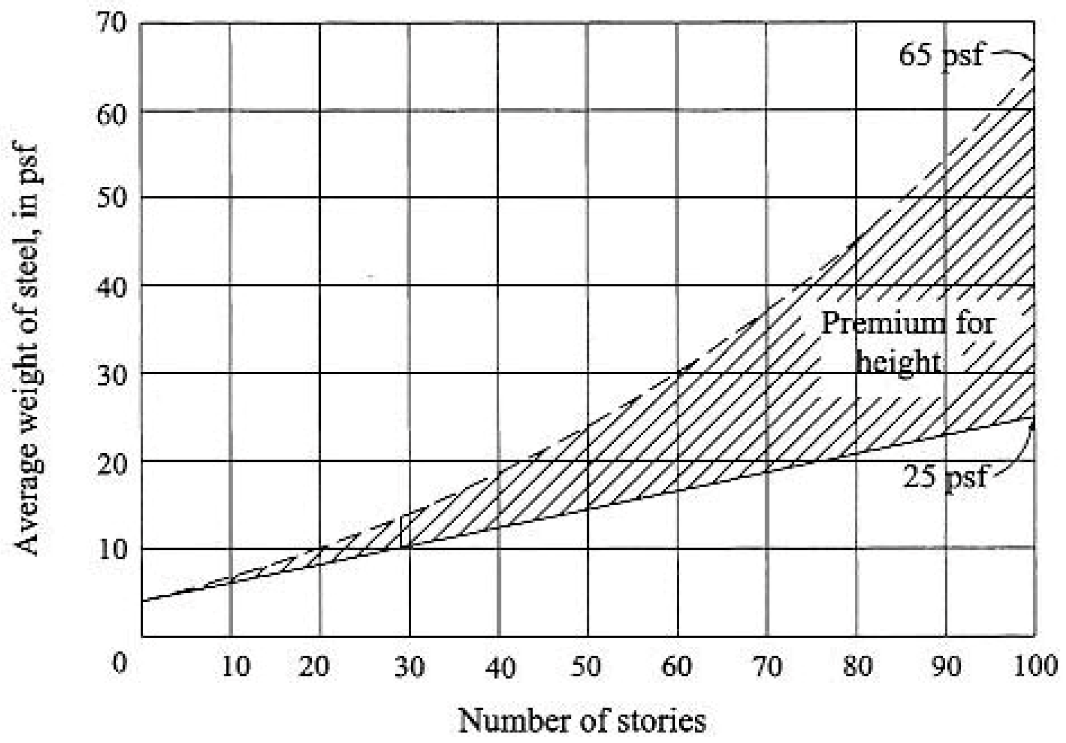
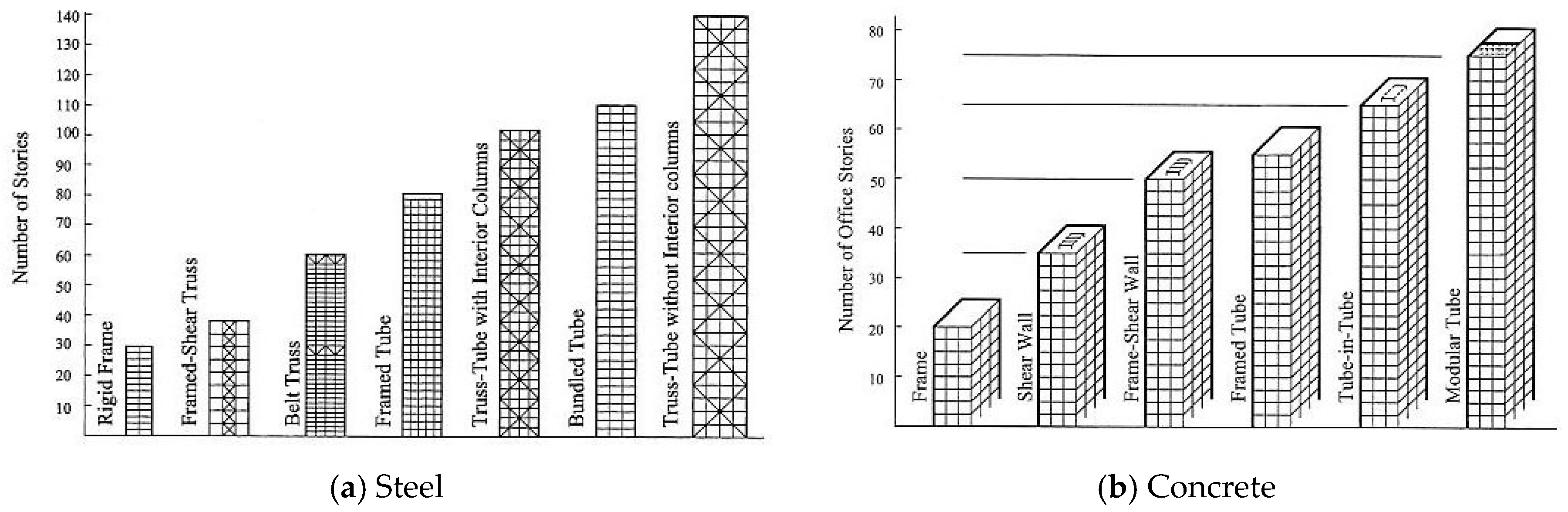
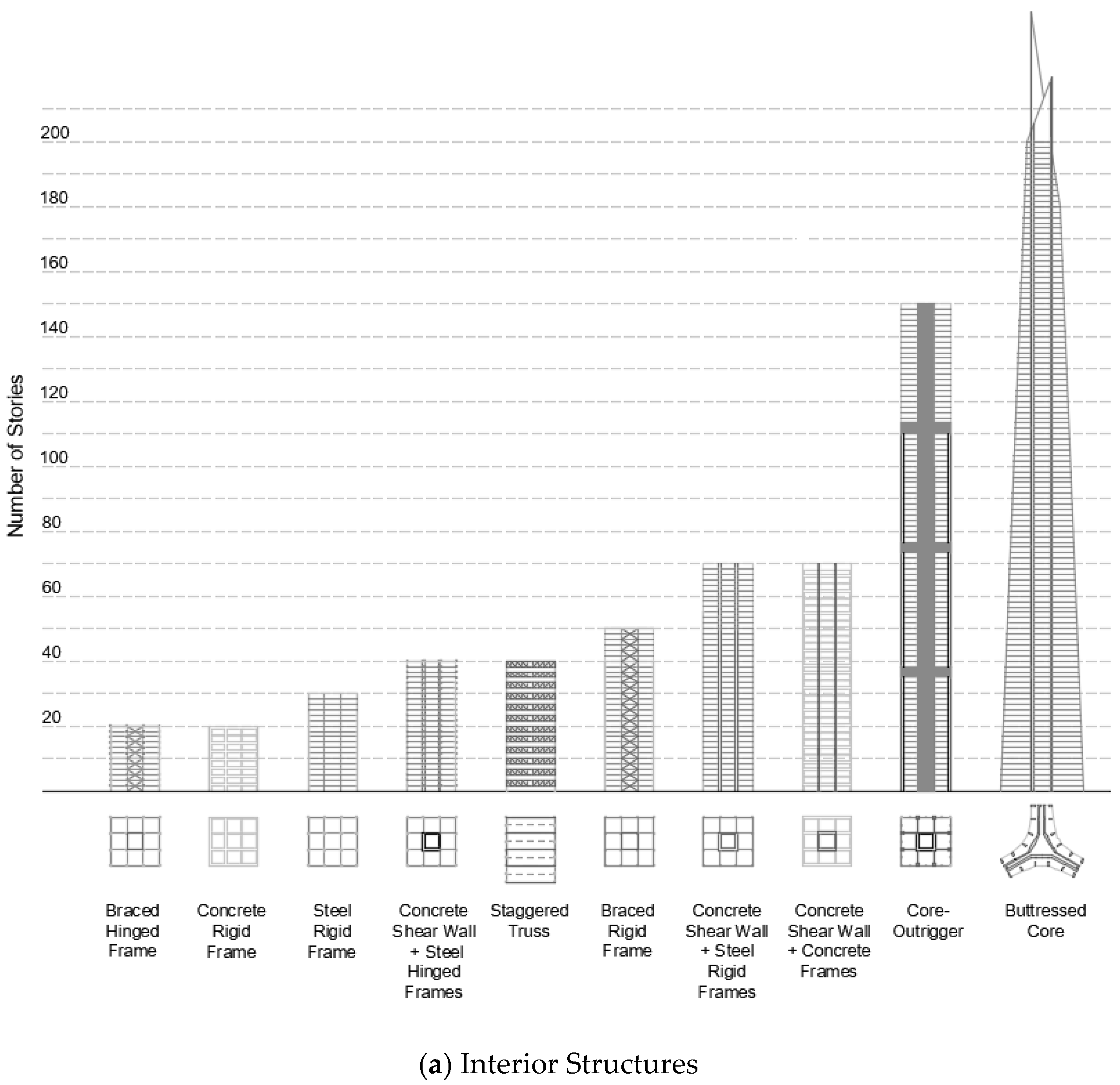
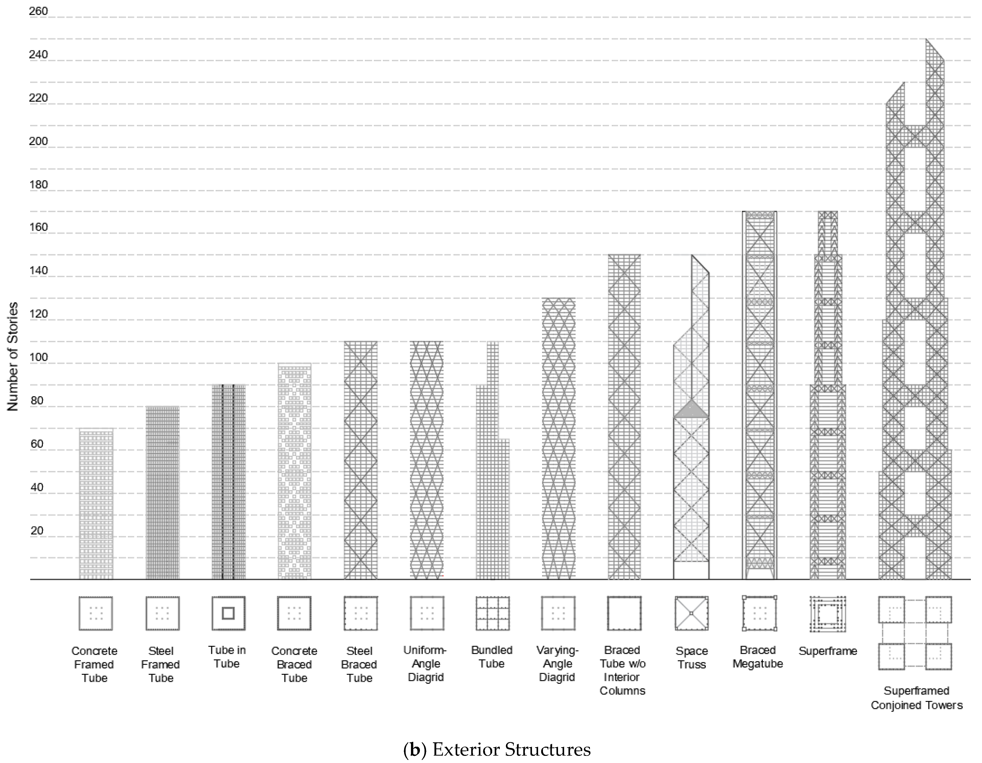
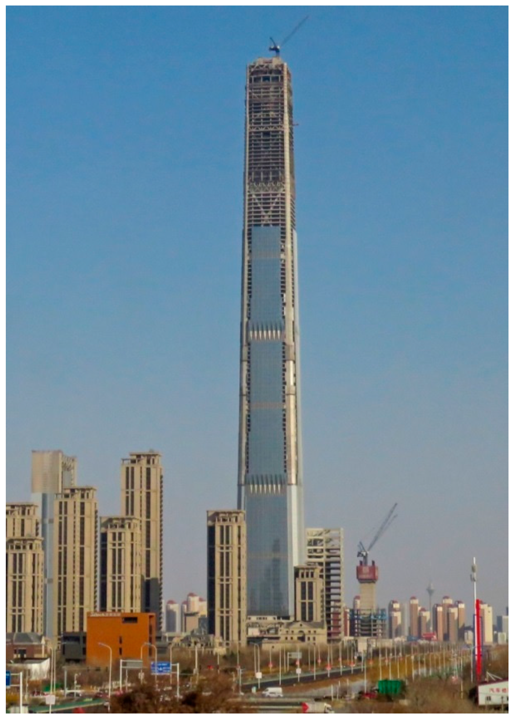
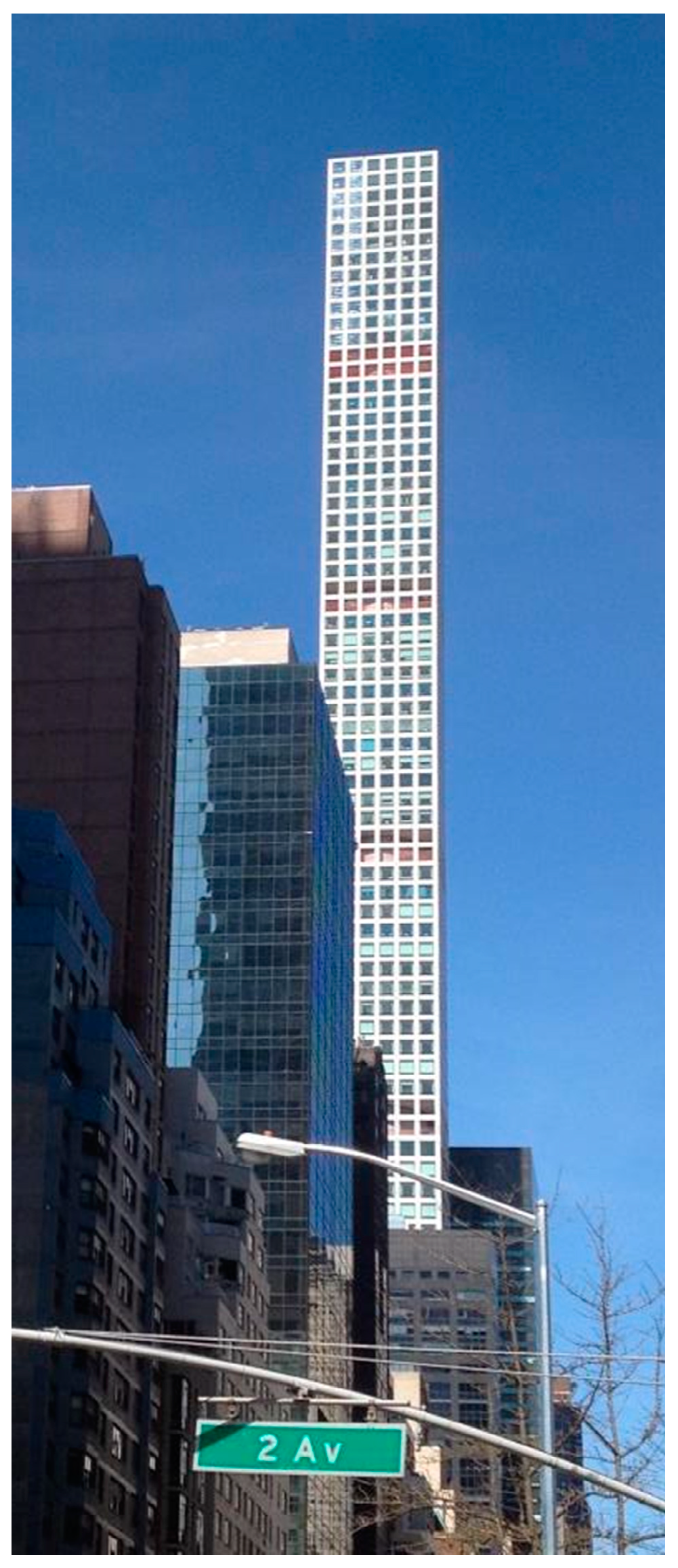
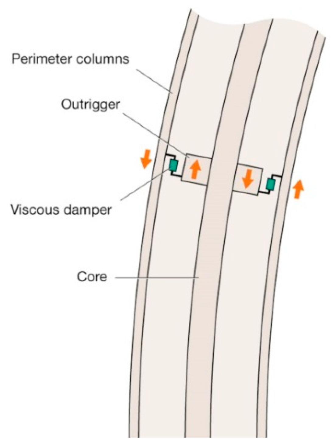
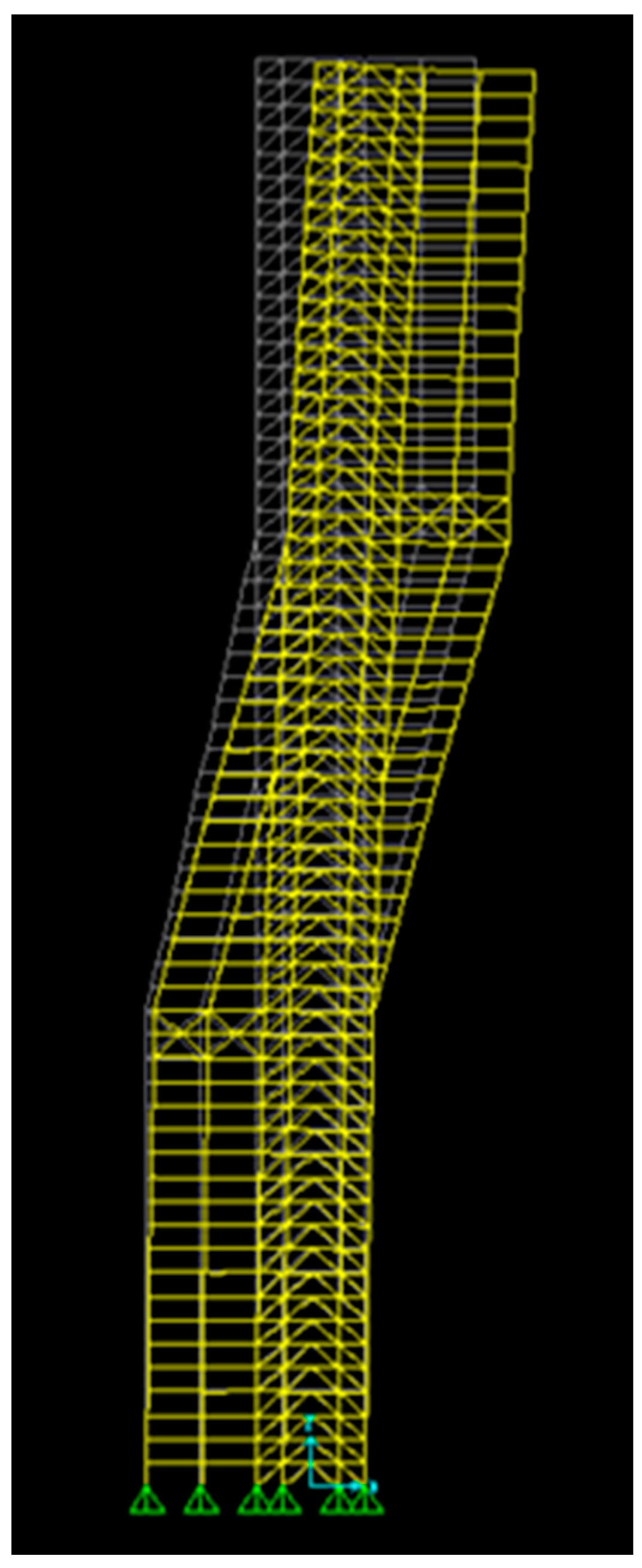
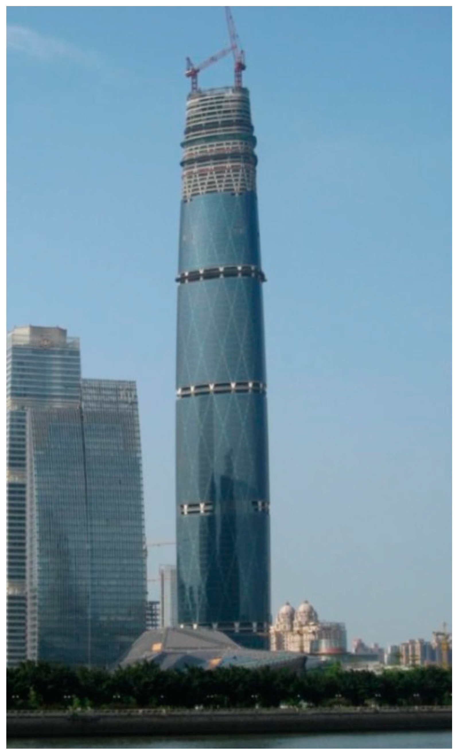
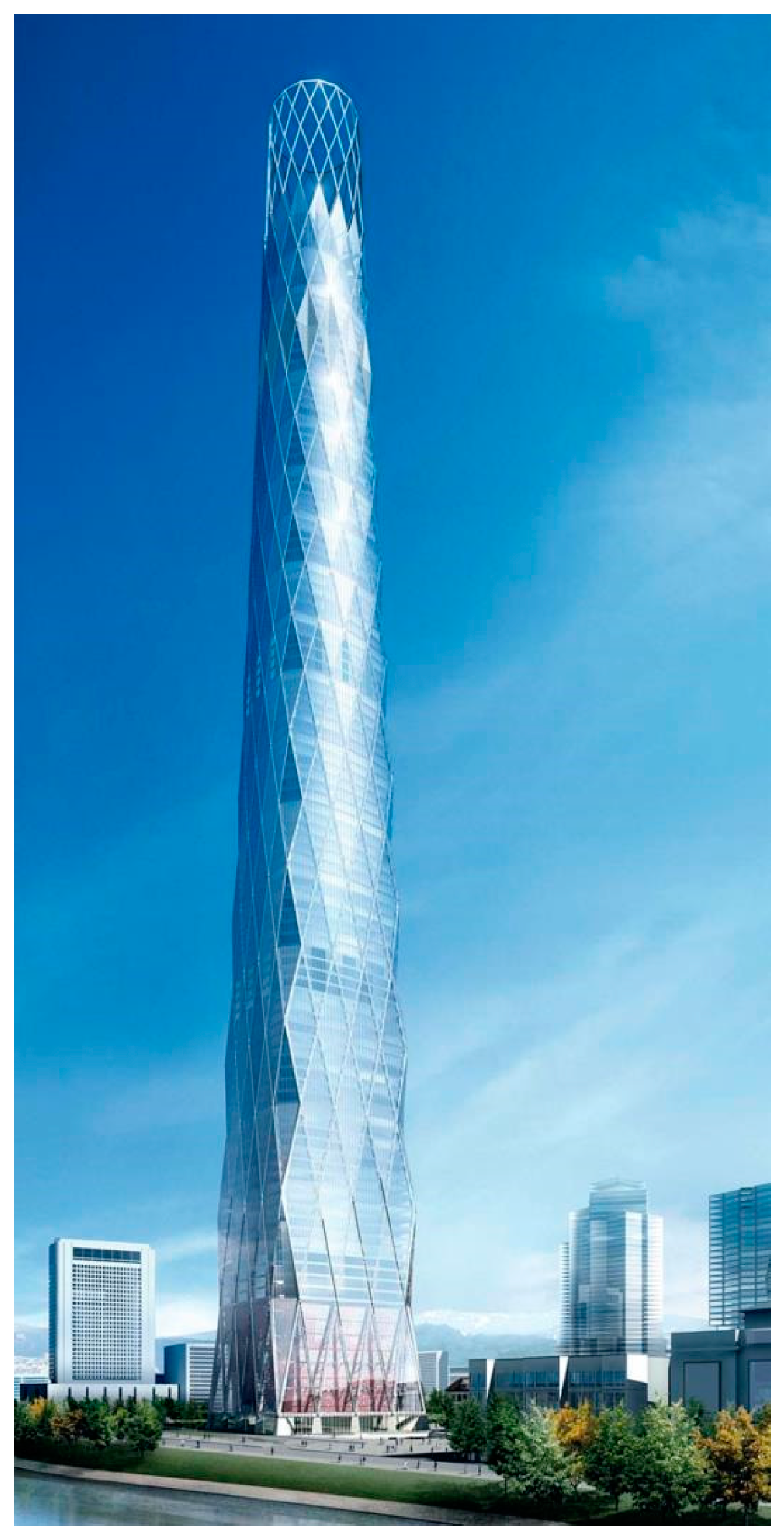
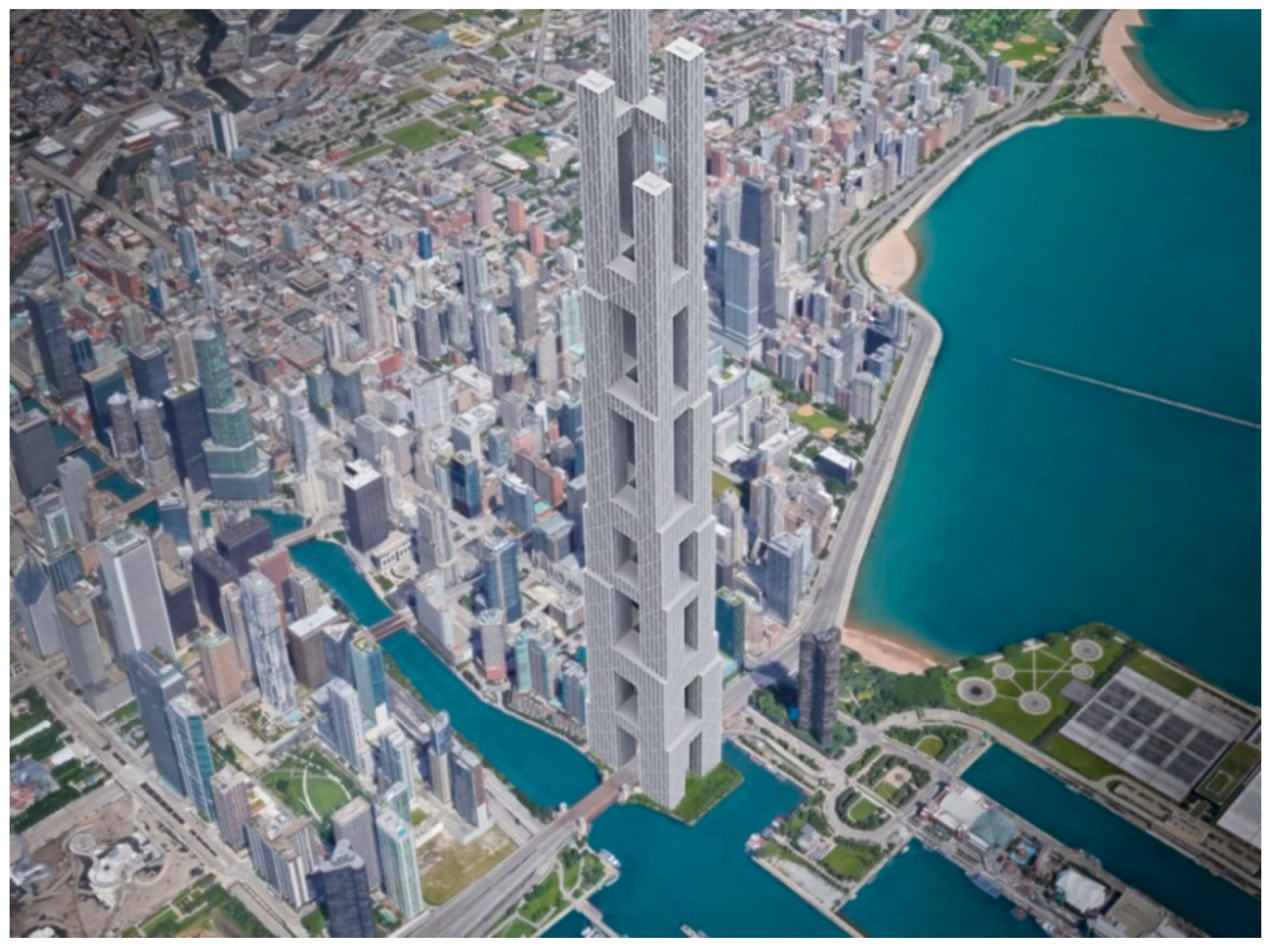
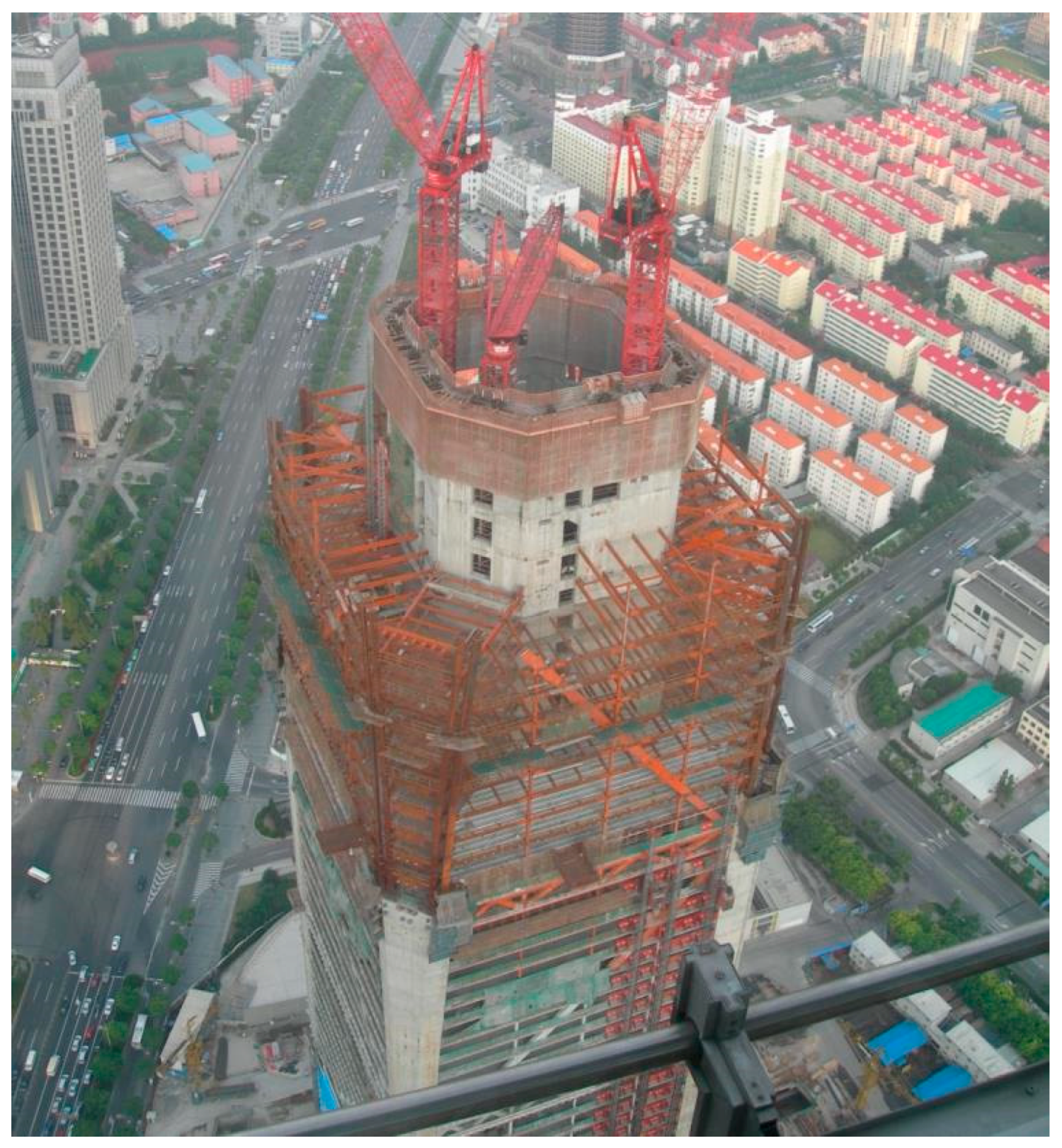
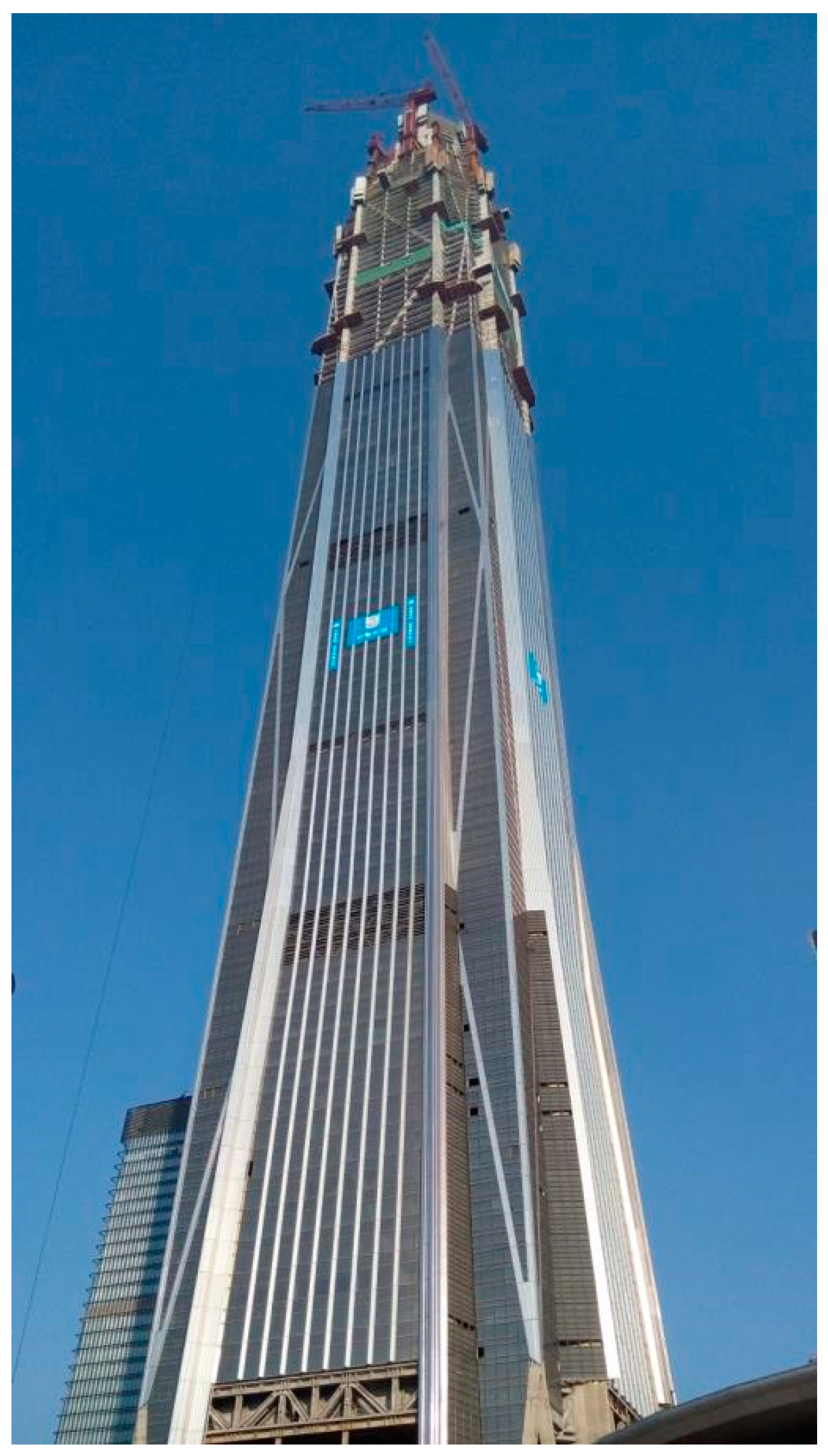
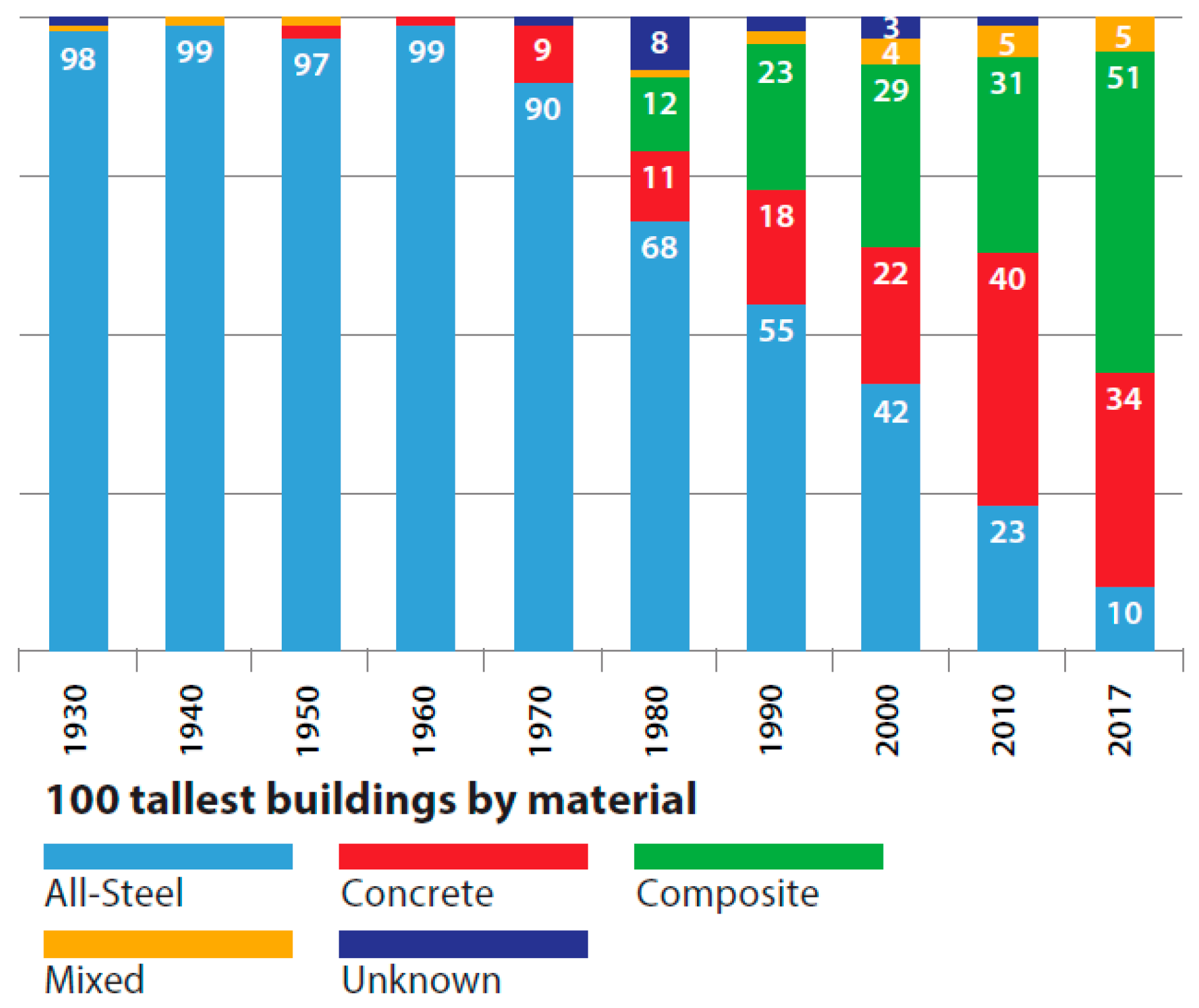
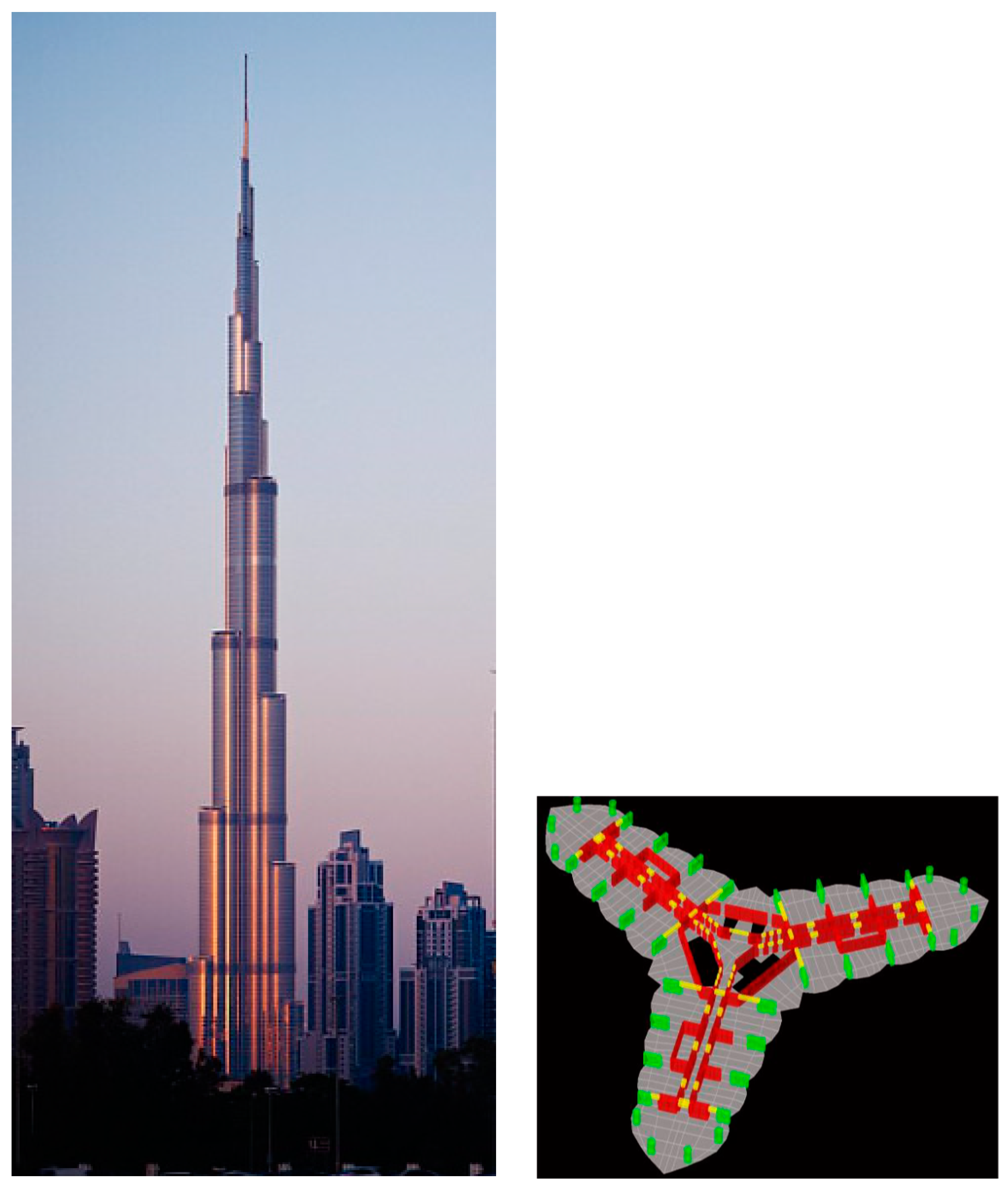
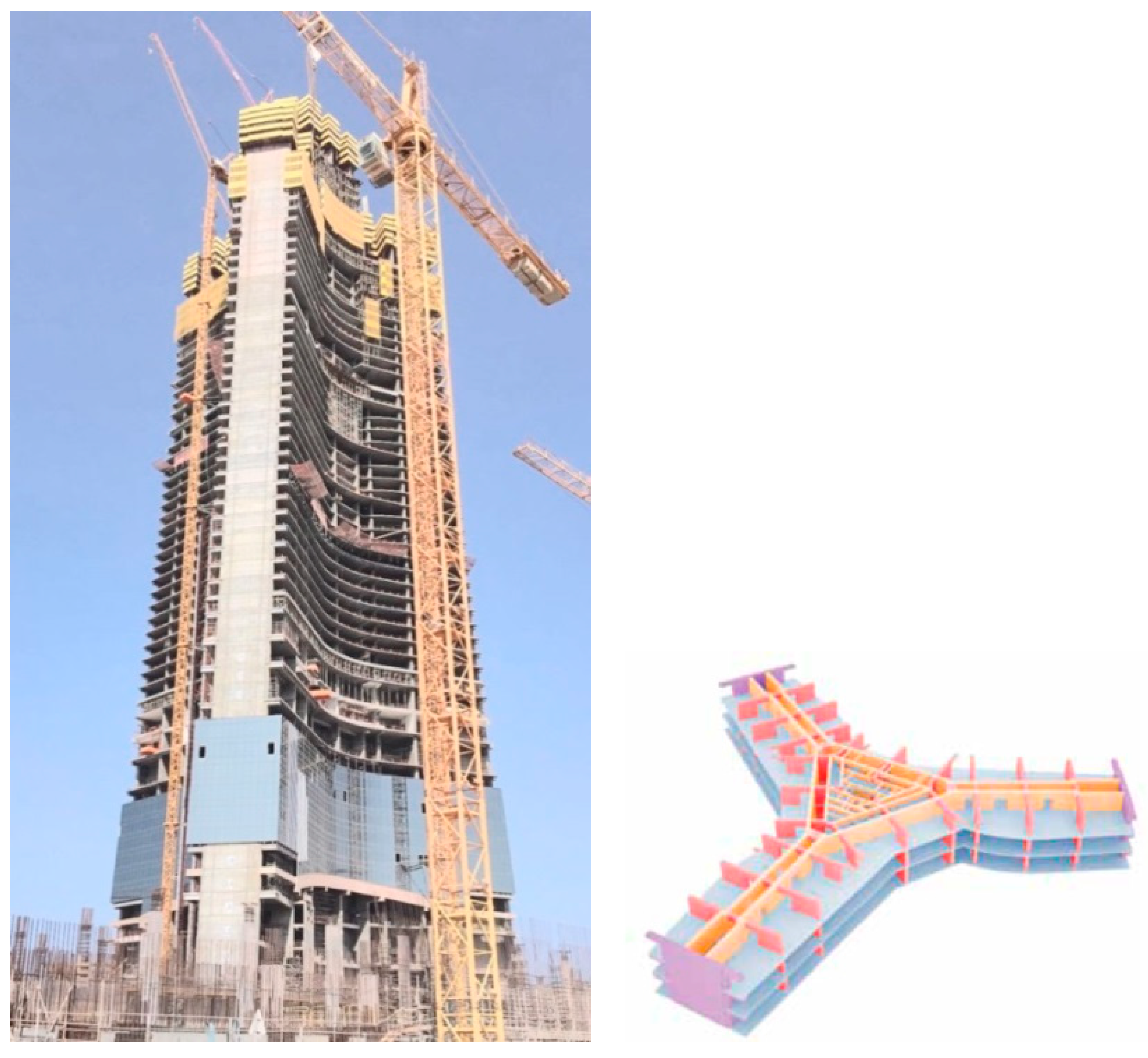
Table 1.
Interior Structures.
| Category | Sub- Category | Material/ Configuration | Efficient Height Limit | Advantages | Disadvantages | Building Examples |
|---|---|---|---|---|---|---|
| Rigid Frame | _ | Steel | 30 | Provides flexibility in floor planning. Fast construction. | Expensive moment connections. Expensive fire proofing. | 860 & 880 Lake Shore Drive Apartments (1951, Chicago, 26 stories, 82 m), BMA Tower (1961, Kansas City, 19 stories, 85 m), One Woodward Avenue (1963, Detroit, 28 stories, 131 m), Tokyo Marine Building (1990, Osaka, 27 stories, 118 m) |
| Concrete | 20 | Provides flexibility in floor planning. Easily moldable. | Expensive formwork. Slow construction. | Ingalls Building (1903, Cincinnati, 16 stories, 65 m); Numerous buildings under 20 stories. | ||
| Braced Hinged Frame | _ | Steel Shear Trusses + Steel Hinged Frames | 20 | Efficiently resist lateral loads by axial forces in the shear truss members. Allows shallower beams compared with the rigid frames without diagonals. | Interior planning limitations due to diagonals in the shear trusses. Expensive diagonal connections. | Numerous buildings under 20 stories. |
| Shear Wall- Hinged Frame | _ | Concrete Shear Wall + Steel Hinged Frames | 40 | Effectively resists lateral shear by concrete shear walls. | Interior planning limitations due to shear walls. | 77 West Wacker Drive (1992, Chicago, 49 stories, 204 m), Casselden Place (1992, Melbourne, 43 stories, 166 m) |
| Staggered Truss | _ | Steel | 40 | Efficiently resists lateral loads typically with column-free ground floor. Fast construction. Low floor-to-floor height reducing the total height of the building and hence reducing unit cost of steel. | Significant interior planning limitation caused by story-height trusses. Weak in the long direction. | Taj Mahal Hotel (1990, Atlantic City, 42 stories, 131 m), Planet Hollywood Las Vegas (2000, Las Vegas, 39 stories, 119 m), The Godfrey (2014, Chicago, 16 stories, 56 m) |
| Shear Wall (Shear Truss)- Frame Interaction | Braced Rigid Frame | Steel Shear Trusses + Steel Rigid Frames | 50 | Effectively resists lateral loads by producing shear truss - frame interaction system. | Interior planning limitations due to shear trusses | Sanwa Bank (1973, Tokyo, 25 stories, 100 m), Osaka World Trade Center (1995, Osaka, 55 stories, 256 m) |
| Shear Wall/ Rigid Frame | Concrete (or Composite) Shear Wall/Core + Steel Rigid Frames | 70 | Effectively resists lateral loads by producing shear wall-frame interaction system. | Interior planning limitations due to shear walls | First City Tower (1984, Houston, 47 stories, 202 m) | |
| Concrete Shear Wall/Core + Concrete Frames | 70 | “ | “ | Cook County Administration Building (1964, Chicago, 38 stories, 145 m), 311 South Wacker Drive (1990, Chicago, 65 stories, 293 m) | ||
| Core- Outrigger | w/Belt Trusses or Belt Wall (w/ Occasional Virtual Outriggers) | Concrete or Steel or Composite; Core + Outriggers (or Virtual Outrigger) + Belt Trusses or Belt Walls + Perimeter Columns | 80 | Effectively resists overturning moments by perimeter columns connected to the core with outriggers through belt trusses or belt walls. Could be modified to virtual outrigger system by eliminating outriggers and stiffening floors instead to prevent the outrigger- interfered floors. | Outriggers are obstructive inside the floor interfering with occupiable or rentable space thereby usually limiting their placement in mechanical and/or refuge floors. | 140 William Street, formerly known as BHP House (1972, Melbourne, 41 stories, 153 m), U.S. Bank Center, formerly known as First Wisconsin Center (1973, Milwaukee, 42 stories, 183 m), Tower Palace Three (Virtual outrigger system, 1994, Seoul, 73 stories, 264 m) |
| w/Mega- columns (w/ or w/o Belt Trusses or Belt Walls) | Concrete or Steel or Composite; Core + Outrigger + (Belt Trusses or Belt Wall) + Perimeter Megacolumns | 150 | Effectively resists overturning moments by perimeter megacolumns connected to the core with outriggers. Offers the architect more flexibility to articulate the unobstructive façade compared to tube type structures of similar height range. | “ | Jin Mao Tower (1999, Shanghai, 88 stories, 421 m), Taipei 101 (2004, Taipei, 101 stories, 508 m), Shanghai Tower (2015, Shanghai, 128 stories, 632 m), Guangzhou CTF Finance Centre (2016, Guangzhou, 111 stories, 530 m), Lotte World Tower (2017, Seoul, 123 stories, 555 m) | |
| Buttressed Core | _ | Concrete Core + Shear Walls Extending from and Bolstering the Core (+Fin Walls and/or Outriggers to further Stiffen the System) | 200 | Effectively resist lateral loads. Resolves the potential problem of too deep interior spaces for extremely tall buildings with large structural depths required against lateral loads. | Substantial limitations in space use due to the difficulty in creating large open space. | Burj Khalifa (2010, Dubai, 163 stories, 828 m), Wuhan Greenland Center, under construction (Wuhan, 126 stories, 636 m), Jeddah Tower, under construction (Jeddah, 167 stories, 1000+ m) |
Note: “ indicates Same as above.
Table 2.
Exterior Structures.
| Category | Sub- Category | Material/ Configuration | Efficient Height Limit | Advantages | Disadvantages | Building Examples |
|---|---|---|---|---|---|---|
| Framed Tube | _ | Steel | 80 | Efficiently resists lateral loads by locating lateral load resisting systems at the building perimeter. Creates least interference with interior space planning. | Shear lag hinders efficient tubular behavior. Narrow column spacing obstructs the view. | One & Two World Trade Centers, demolished (1972 & 1973, New York, 110 stories, 417 m & 415 m, respectively), Aon Center (1973, Chicago, 83 stories, 346 m) |
| Concrete | 70 | “ | “ | The Plaza on Dewitt, formerly known as Dewitt-Chestnut Apartments (1966, Chicago, 43 stories, 116 m), Water Tower Place (1976, Chicago, 74 stories, 262 m) | ||
| Braced Tube | w/Interior Columns | Steel | 110 | Efficiently resists lateral loads by axial forces in the braced tube members. Wider column spacing compared with framed tubes. Reduced shear lag. | Bracings obstruct the view. | 875 North Michigan Ave, formerly known as John Hancock Center (1969, Chicago, 100 stories, 344 m), First International Building (1974, Dallas, 56 stories, 216 m) |
| Concrete | 100 | “ | “ | 780 Third Avenue (1983, New York, 49 stories, 174 m), Onterie Center (1986, Chicago, 58 stories, 174 m) | ||
| w/o Interior Columns | Steel or Composite | 150 | Can be taller than conventional braced tubes with interior columns due to reduced uplift forces. | Requires very long span floor structures which must span the entire building width. | No built example yet. | |
| Braced Megatube | Composite | 170 | More efficiently resist overturning moment by corner megacolumns than conventional braced tubes. Perimeter gravity columns between the corner megacolumns can easily be designed with progressive collapse- preventing mechanism. | Bracings obstruct the view. | Goldin Finance 117, under construction (Tianjin, 128 stories, 597 m), Citic Tower, formerly known as China Zun Tower, under construction (Beijing, 108 stories, 528 m), Erewhon Center, unbuilt (Chicago, 207 stories, 841 m) | |
| Bundled Tube | _ | Steel | 110 | Reduces shear lag compared to framed tubes. | May cause overall interior planning limitations due to intermediate interior column lines. | Willis Tower, formerly known as Sears Tower (1974, Chicago, 108 stories, 442 m) |
| Concrete | 110 | “ | “ | One Magnificent Mile (1983, Chicago, 57 stories, 205 m), Carnegie Hall Tower (1991, New York, 60 stories, 231 m) | ||
| Diagrid | Uniform- Angle Diagrid | Steel | 100 | Efficiently resists lateral loads by axial forces in the diagrid members. | Complicated joints. Many diagonals could be obstructive. | 30 St. Mary Axe (2004, London, 41 stories, 180 m), Hearst Tower (2006, New York, 46 stories, 182 m), Tornado Tower (2008, Doha, 51 stories, 195 m) |
| Concrete | 80 | “ | Expensive formwork. Slow construction. | O-14 Building (2010, Dubai, 24 stories, 106 m), Doha Tower (2012, Doha, 46 Stories, 238 m) | ||
| Composite | 110 | “ | Slow construction. | Guangzhou International Finance Center (2010, Guangzhou, 103 stories, 439 m) | ||
| Varying- Angle Diagrid | Steel or Composite | 130 | More efficiently carry lateral loads than the uniform angle diagrids for taller and slenderer buildings. | Construction can be more costly than uniform-angle diagrids. | Lotte Super Tower, unbuilt (Seoul, 112 stories, 555 m) | |
| Tube-in-Tube | _ | Ext. Tube (Steel, Concrete or Composite) + Int. Core Tube (Steel, Concrete or Composite) | 90–150 per different tube combo | Effectively resists lateral loads by two layers of tubes. | Interior planning limitations due to interior core tube. | One Shell Plaza (1970, Houston, 52 stories, 218 m), 181 West Madison (1990, Chicago, 50 stories, 207 m), 432 Park Avenue (2015, New York, 85 stories, 426 m) |
| Space Truss | _ | Composite | 150 | Efficiently resists lateral loads by axial forces in the space truss members. | Bracings obstruct the view. | Bank of China (1990, Hong Kong, 72 stories, 367 m) |
| Superframe | Stand-alone | Steel | 170 | Efficiently resists lateral loads by the versatile superframe configurations. | Building form depends to a great degree on the structural system. | Chicago World Trade Center, unbuilt (Chicago, 168 stories, 690 m estimated.) |
| Concrete | 100 | “ | “ | Parque Central Towers I & II (Caracas, 56 stories, 225 m) | ||
| Conjoined Towers | Composite | 250+ | Could efficiently produce extremely tall building complex. Multiple emergency egress alternatives. | Requires very large sites. | No built example yet. |
Note: “ indicates Same as above.
© 2018 by the authors. Licensee MDPI, Basel, Switzerland. This article is an open access article distributed under the terms and conditions of the Creative Commons Attribution (CC BY) license (http://creativecommons.org/licenses/by/4.0/).
Share and Cite
MDPI and ACS Style
Ali, M.M.; Moon, K.S. Advances in Structural Systems for Tall Buildings: Emerging Developments for Contemporary Urban Giants. Buildings 2018, 8, 104. https://doi.org/10.3390/buildings8080104
AMA Style
Ali MM, Moon KS. Advances in Structural Systems for Tall Buildings: Emerging Developments for Contemporary Urban Giants. Buildings. 2018; 8(8):104. https://doi.org/10.3390/buildings8080104
Chicago/Turabian StyleAli, Mir M., and Kyoung Sun Moon. 2018. "Advances in Structural Systems for Tall Buildings: Emerging Developments for Contemporary Urban Giants" Buildings 8, no. 8: 104. https://doi.org/10.3390/buildings8080104
Note that from the first issue of 2016, this journal uses article numbers instead of page numbers. See further details here.