Development of an Innovative Modular Foam-Filled Panelized System for Rapidly Assembled Postdisaster Housing


Centre for Infrastructure Engineering, Western Sydney University, Kingswood, NSW 2747, Australia
*
Author to whom correspondence should be addressed.
Buildings 2018, 8(8), 97; https://doi.org/10.3390/buildings8080097
Submission received: 21 June 2018
/
Revised: 16 July 2018
/
Accepted: 28 July 2018
/
Published: 30 July 2018
(This article belongs to the Special Issue Modern Prefabricated Buildings)
Abstract
:In this paper, the development process of a deployable modular sandwich panelized system for rapid-assembly building construction is presented, and its structural performance under some different action effects is investigated. This system, which includes an innovative sandwich panel and its integrated connections, can be used as structural walls and floors in quickly-assembled postdisaster housing, as well as load-bearing panels for prefabricated modular construction and semipermanent buildings. Panels and connections are composed of a pneumatic fabric formwork, and two 3D high-density polyethylene (HDPE) sheets as the skins, filled with high-density rigid polyurethane (PU) foam as the core. HDPE sheets manufactured with a studded surface considerably enhance stress distribution, buckling performance, and delamination strength of the sandwich panel under various loading conditions. The load-carrying behavior of the system in accordance with some American Society for Testing and Materials (ASTM) standards is presented here. The results show the system satisfies the codes’ criteria regarding semipermanent housing.
1. Introduction
Natural disasters and emergencies can devastate the communities they hit, and the speed of a response can be crucially important. Crisis management after natural and non-natural disasters, such as earthquakes, floods, droughts, bushfires, refugees, raids, and even wars is one of the significant concerns of governments, where fast decision-making is an essential element of an effective crisis management system. When a large number of houses have suffered damages and become unusable, causing a high number of homeless people, rapid housing-reconstruction programs play a decisive role in disaster recovery and providing temporary housing is a crucial step of these programs. Experts estimate that, on average, it can take 5 to 10 [1,2] years for communities to recover from the effects of a major seismic event, which highlights the severity of the disaster and the importance of rapidly assembled buildings as an effective postdisaster housing system. In addition to residential accommodation, rapid-assembly buildings can be employed in several other applications, such as field hospitals, storehouses, and other temporary and semipermanent facilities. Some rapidly assembled systems have the potential to be used as temporary structures as well as provide long-term serviceability. Abulnour [3] defined temporary dwellings as a step toward permanent houses in a disaster recovery and reconstruction plan, and classified them into two distinct categories: (i) Temporary shelter, used to incubate people immediately after a disaster; and (ii) temporary housing, allowing the return to normal daily activities, e.g., work, school, cooking at home, and shopping.
Mobile and rapidly assembled structures play a major role in postdisaster management through building temporary accommodation and shelters. These types of structures are also of primary importance in many military and civilian service applications and are widely used for rescue and maintenance services. Air-liftable origami-inspired deployable systems, pliable structural systems with rigid couplings for parallel leaf-springs, scissor systems, elastic grid shell systems, and structural panels are some popular types of mobile and rapidly assembled structures [4]. Some successful attempts on employing paper tube arches for temporary structures have also been discussed by Preston and Bank [5].
A wise selection of rapid-assembly building systems has an impact on their performance in an effective crisis management system. For instance, while use of big precast structural elements is very common for postdisaster housing, as the dimension of precast elements increases, some significant construction problems will appear in transportation and erection phases. A temporary accommodation building can be any class of building as defined under the National Construction Code (NCC) [6]: Class 1b (boarding house, guest house, hostel, or the like), class 2 (residential units), or class 3 (motel) building, depending on its configuration [7]. Among the existing systems, air-liftable origami-inspired deployable systems, pliable structural systems with rigid couplings for parallel leaf-springs, scissor systems [8], elastic grid shell systems [9], and structural panels are some popular types of mobile and rapidly assembled structures [10,11]. However, most of these rapidly assembled structural systems suffer from low tolerance in the making and erection phases and need skilled labors for installation that will result in an increase in total construction costs and lower efficiency.
Lightweight structural panels are one of the most popular types of mobile and rapidly-assembled structures. Rapidly assembled panels are a form of modular construction, commonly used in residential buildings as well as industrial structures [12,13,14]. A wide range of these panels is made from new lightweight components such as foams. Many types of foams are on the market and polyurethane (PU) foams are the most popular types [15]. Low self-weight and relatively high stiffness and durability have increased the demand for this type of composite structures [16]. Foam-filled sandwich construction, characterized by two relatively thin and stiff faces and a relatively thick and lightweight foam-core, is becoming an interesting solution for prefabricated building wall and floor systems.
With regard to the literature, a wide range of studies on the foam-filled composite panels are on those made of PU foam-core [17]. The results of these studies indicate that the stiffness and strength of a majority of conventional foam-filled sandwich panels hardly meet the structural requirements for use in building floors or walls, at least for standard spans and loads, mainly due to different failure modes, such as delamination of the skins from the core, buckling or wrinkling of the compression skin, flatwise crushing of the core, or rupture of the tension skin. The main weaknesses of these panels stem from the low stiffness and strength of the core, and the skin’s susceptibility to delamination and buckling, owing to the local mismatch in stiffness and the lack of reinforcements bridging the core and the skins [18]. The use of stitches for connecting the two side skins [19] or use of reinforcing ribs [20] are two popular strengthening techniques being employed for improving the mechanical performance of standard sandwich panels. Despite their very competitive costs, conventional foam-filled sandwich panels are susceptible to some different failure modes. Delamination of the skins from the core, buckling or wrinkling of the compression skin, flatwise crushing of the core, and rupture of the tension skin are some of the very common types of failure.
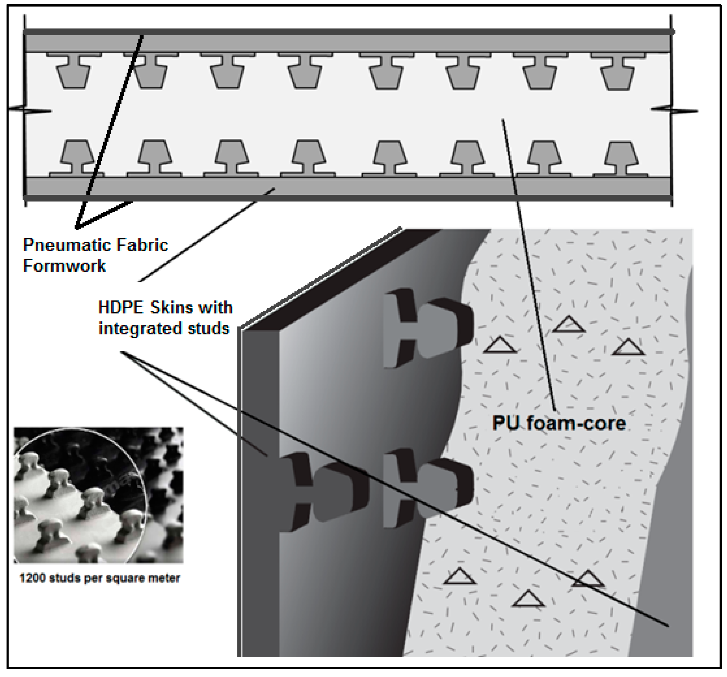
In this study, in order to enhance the properties of the foam-filled sandwich panels with regard to such failure modes for application in semi-temporary housing, a new sandwich system is proposed, in which 3D high-density polyethylene (HDPE) sheets with 2 mm thickness are used as the skins, and high-density PU foam is used as the core, as illustrated in Figure 1, with a total thickness of 100 mm. The system is cast in a pneumatic fabric formwork, which is used to accelerate installation and simplify the transposition process. Using the HDPE sheets, manufactured with approximately 1200 studs per square meter, higher pullout, and delamination strength, as well as better stress distribution and buckling performance can be achieved. The studs also improve the resistance of the face sheets and foam-core from debonding and increasing the interface strength between the foam-core and the face sheets.
The fabrication of these sandwich panels takes place in a single step. Therefore, the face sheets and foam-core are integrated into one construction in the fabric formwork. Rapid assembly, lightweight and easy transportation, durability, and a wide range of applications are some merits of this new design. Given that the introduction of a new design typically brings new challenges to designers to utilize the new properties of the materials and geometry, the main goal of this research work is to investigate some structural properties of the newly-developed sandwich system.
2. Materials and Methods
To evaluate basic material properties, in addition to using manufacturers’ data, some experimental tests were performed.
2.1. Foam-Core
Rigid foam systems are energy-efficient, versatile, high-performance systems, where liquid components are mixed together and expand and harden on curing. Rigid PU foam is one of the most efficient, high-performance insulation materials, enabling very effective energy savings with minimal occupation of space. A 100 mm thick layer of rigid PU provides a U-value of 0.04, which demonstrates high insulation performance of PU foam [21]. U-values measure how effective a material is an insulator. The lower the U-value is, the better the material is as a heat insulator.
The popular type of PU foam being used for thermal insulation, refrigeration, and water heater systems is made of a 100:100–110 weight ratio mixture of AUSTHANE POLYOL AUW763 and AUSTHANE MDI [22]. This foam is formulated using a zero Ozone Depletion Potential (ODP), zero Global Warming Potential (GWP), and Volatile Organic Compound (VOC) exempt blowing agents. In this study, high-density rigid PU foam with a density of 192 kg/m3 was selected for the core material according to the results of the preliminary finite element models. Table 1 and Figure 2 show the PU foam’s manufacturing and mechanical properties, provided by the manufacturer and validated in the laboratory according to the ASTM 1730 [23] standard specification for rigid foam for use in structural sandwich panel cores. It also meets the thermal conductivity, dimensional stability, and flame resistance requirements of ASTM E1730 [23]. In Table 1, “cream time” is a measure of the beginning of the foam reaction, characterized by a change in the liquid’s color as it begins to rise; “gel time” is the time when the foam has developed enough gel strength to be dimensionally stable; “track free time” is the time between the beginning of the foam pour and the point at which the outer skin of the foam loses its stickiness; and “free rise density” is the weight per unit volume of the foam that can be free rise or packed into a mold. The compressive force is to be applied parallel to the rise direction of the foam, and the compressive strength is determined in accordance with Procedure A of Test Method D1621, or by Test Method C165. The tensile force is to be applied parallel to the rise direction of the foam, and the tensile strength is determined in accordance with Test Method D1623. Shear force is applied perpendicular to the rise direction of the foam, and shear strength was determined in accordance with Test Method C273/C273M.
The yielding behavior can be explained by the buckling of the foam’s internal walls. Scanning Electron Microscopic (SEM, JEOL, Sydney, Australia) images, provided before and after compression test, substantiate such behavior. A long and rather flat plateau was followed. Then, a densification (hardening) region was created by gradual stress increase when the cell walls were stacked prior to final densification. In this range of loading, no visible signs of failure were observed. Residual displacement of the collapsed foam, however, occurs once the unloading stage was complete.
2.2. Fabric Formwork
For the selection of a formwork system, some criteria are usually taken into account: Quality (strength, rigidity, position, and dimensions); safety (both of workers and the concrete structure); efficiency (in operation, handling, erection and dismantling, and number of repetitions); and economy (life cycle cost to be consistent with quality and safety). Fabric formworks offer lower weight (approximately 1/300th that of a conventional rigid form), lower material cost, lower labor cost (no cost of stripping, placing, erection, and waterproofing), and better constructability (adaptable to uneven ground conditions, easier infill protection, and stakeless system). These make the use of fabric a viable option, especially for rapid-assembly construction [24].
Although fabrics have been used as formwork for many years [25], thanks to recent advances in the textile material science, durable and low-cost fabrics are becoming increasingly available for construction purposes. Using fabric formwork as a mold in concrete structure, it is possible to cast architecturally interesting, structurally optimized nonprismatic structures that use up to 40% less concrete in comparison with an equivalent prismatic section [24], offering potentially significant embodied energy savings [26], and, subsequently, a striking reduction in CO2 emissions [27] can be achieved.
There are two general types of fabric formworks: Slack-sheet mold and energized (tensioned) formwork sheets [28]. Each type of fabric distributes force slightly differently depending on the material it is made of and the nature of its internal structures. This study will focus on pneumatic fabric formworks, in which pneumatic force is used for the erection of the flexible fabric formwork. The critical aspect of fabric formwork for achieving desirable performance is the selection of the fabric itself. Although a wide range of woven fabrics can be used as formwork for fabric formwork, tensile strengths in both warp and weft directions must be sufficient to hold the infill material (which is PU in this research) and a low creep modulus is desirable to limit formwork deformations during casting and curing/hardening.
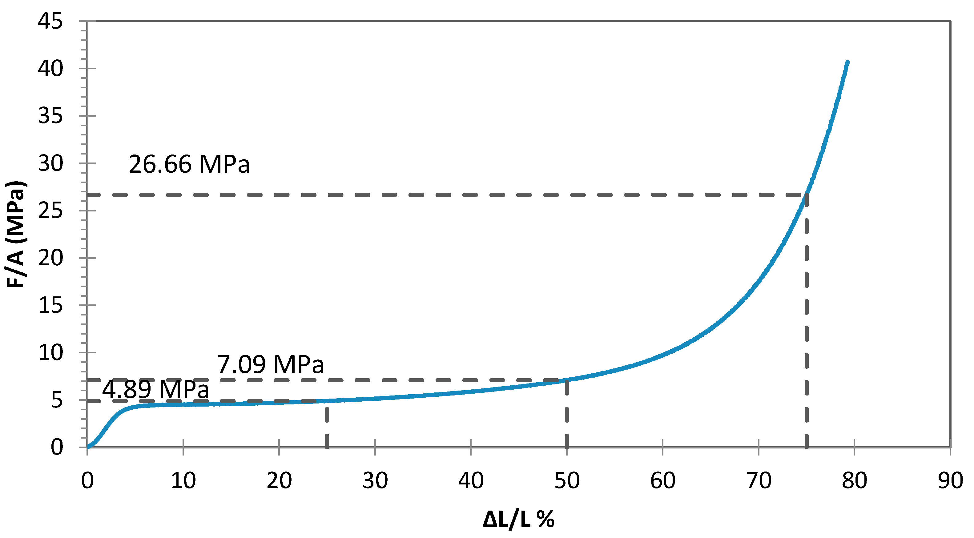
For the selection of the fabric, criteria such as aesthetics, permeability, sewability or weldability, relative cost, durability, and strength were considered [29]. Conducting some experimental tests to determine the selection indicators for criteria like durability and strength for each candidate, we selected Barrateen as the most suitable pneumatic formwork candidate for foam-filled structural composite panels. Barrateen fabric is an HDPE-coated unbalance woven textile. The coating material is low-density polyethylene and well inflatable. In addition, its tensile strengths in the warp and weft directions are not the same. The result of tensile tests on 10 cm wide and 20 cm long specimens according to D5034–09 [30] showed that the module of elasticity of the principal direction is higher, but, in strain about 270%, it can have a sudden brittle rupture (Figure 3). The test is designed for determining the breaking strength and elongation of textile fabrics, and is applicable to woven, nonwoven, and felted fabrics. A series of weldability tests were also conducted on the fabric; the tensile-bearing capacity of heat-welded connections can reach up to 13% of the average strength of the material. In addition, the maximum strain was measured as 90% at the failure point.
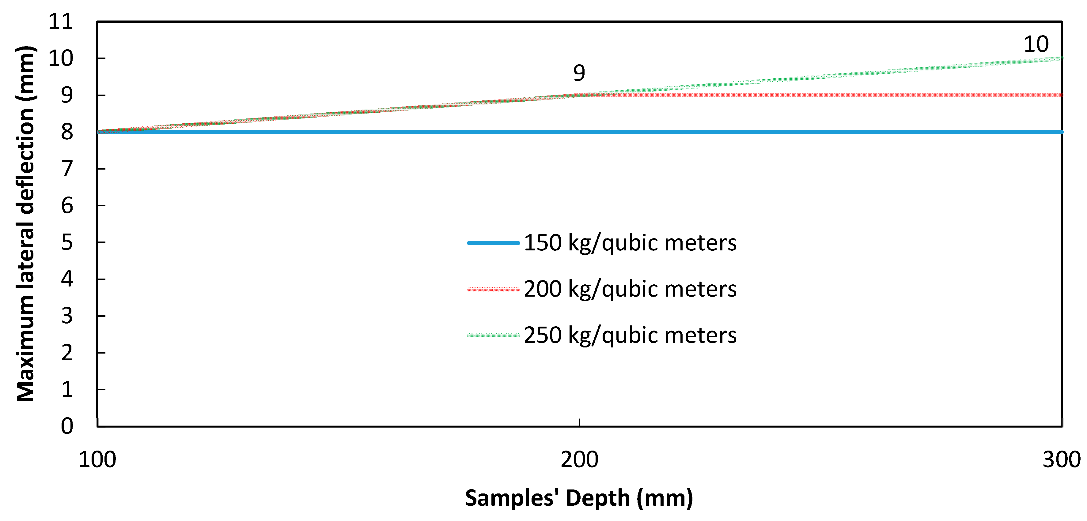
With regard to the structural performance of the fabric formwork, some experimental tests were conducted. Formwork should be designed for the ultimate as well as serviceability limit states. Low-yield stress and plastic viscosity of filling material increase the lateral pressure on the forms to a degree as high as the hydrostatic pressure. That is, formwork pressure exists as long as filling material is in a plastic state, and its rate of decay is related to the rate of the stiffening of filling material [31]. Figure 4 depicts the effects of formwork thickness and foam density on the maximum lateral deflection of the fabric formwork. It shows higher thickness will result in higher effects of density of the maximum lateral deflection.
2.3. Skin Sheets
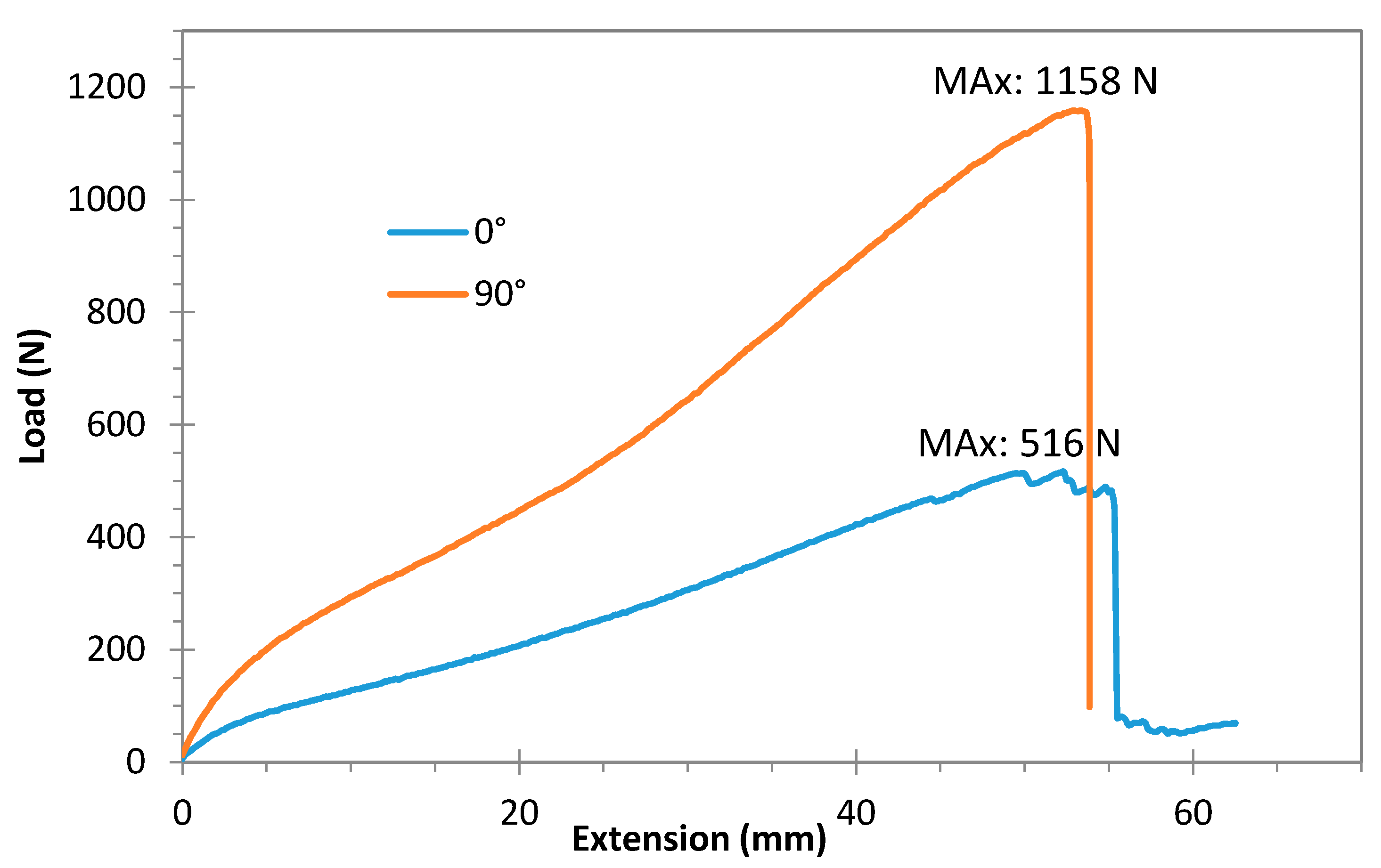
The face sheets of the sandwich panels are made of 3D HDPE sheets primarily produced as a concrete embedment liner to provide protection from mechanical damage and a corrosive and erosive environment. In addition to resistance to chemical and environmental threats, its relatively high strength, and, in particular, its 3D studded face with approximately 1200 studs per square meter, can effectively contribute to the sandwich composites’ structural performance by providing high pullout strength, minimum lateral movement of the skin, and stronger bonding. Four different thicknesses of the sheets were initially investigated (2 mm, 3 mm, 4 mm, and 5 mm), and, at the end, the sheets with 2 mm tackiness were selected for the sandwich composite. Figure 5 shows mechanical properties of the selected sheet provided by the manufacturer and validated by experimental tests in the laboratory, in accordance with the ASTM D5199, ASTM D1505, and ASTM D6693 provisions [32] at a loading rate of 5 mm/min. In order to identify the structural behavior of the skin, inplane tensile tests were conducted on two principal perpendicular directions (lengthwise and crosswise) of the HDPE sheets, using a universal hydraulic testing machine, according to the ASTM D6693 standard [32]. Figure 5 shows the coupon test results.
3. Edgewise and Flatwise Compressive Behavior
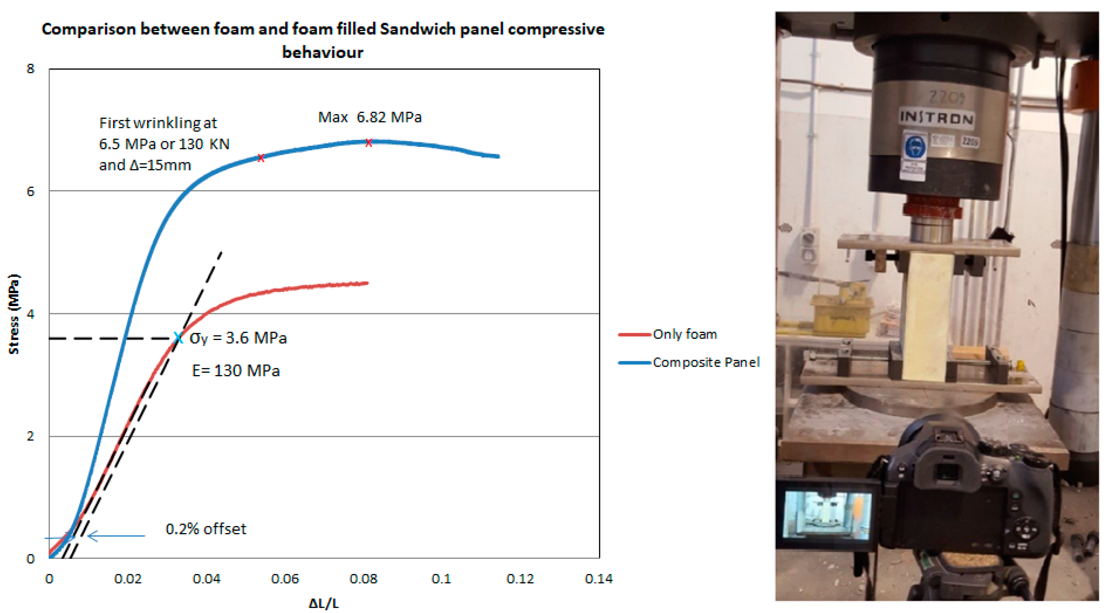
Edgewise compressive strength of sandwich construction is important as it provides the basis for the assessment of load-carrying capacity [33]. The compressive properties of the sandwich composite along the direction parallel to the plane of the sandwich face skin were evaluated through edgewise compression tests on 100 mm × 200 mm × 300 mm samples using a test rig (universal testing machine) in accordance with the ASTM C364 standard [34]. This test method consists of subjecting a sandwich panel to monotonically increasing compressive force parallel to the plane of its faces. The force is transmitted to the panel through either clamped or bonded end supports. Stress and strength are reported in terms of the nominal cross-sectional area of the two face sheets, rather than total sandwich panel thickness, although alternate stress calculations may be optionally specified.
For design purposes, the nonlinear behavior of the stress–strain relationship can be approximated by two linear behaviors with different stiffness. The initial portion can be used to determine the initial elastic modulus using regression analysis of the data up to 2% strain. Due to the significant nonlinear behavior observed beyond the strain level of 2%, the second slope, conservatively representing the reduced elastic modulus can be determined approximately based on the data measured between strains of 4% up to failure strain. These two calculated slopes are extended between 2% and 4% strain until they intersect each other in order to obtain the full approximation of the compressive edgewise behavior (Figure 6). Specific geometric factors that affect edgewise compressive strength of sandwich panels include face-sheet fiber waviness, core cell geometry (shape, density, orientation), core thickness, and specimen shape (L/W ratio).
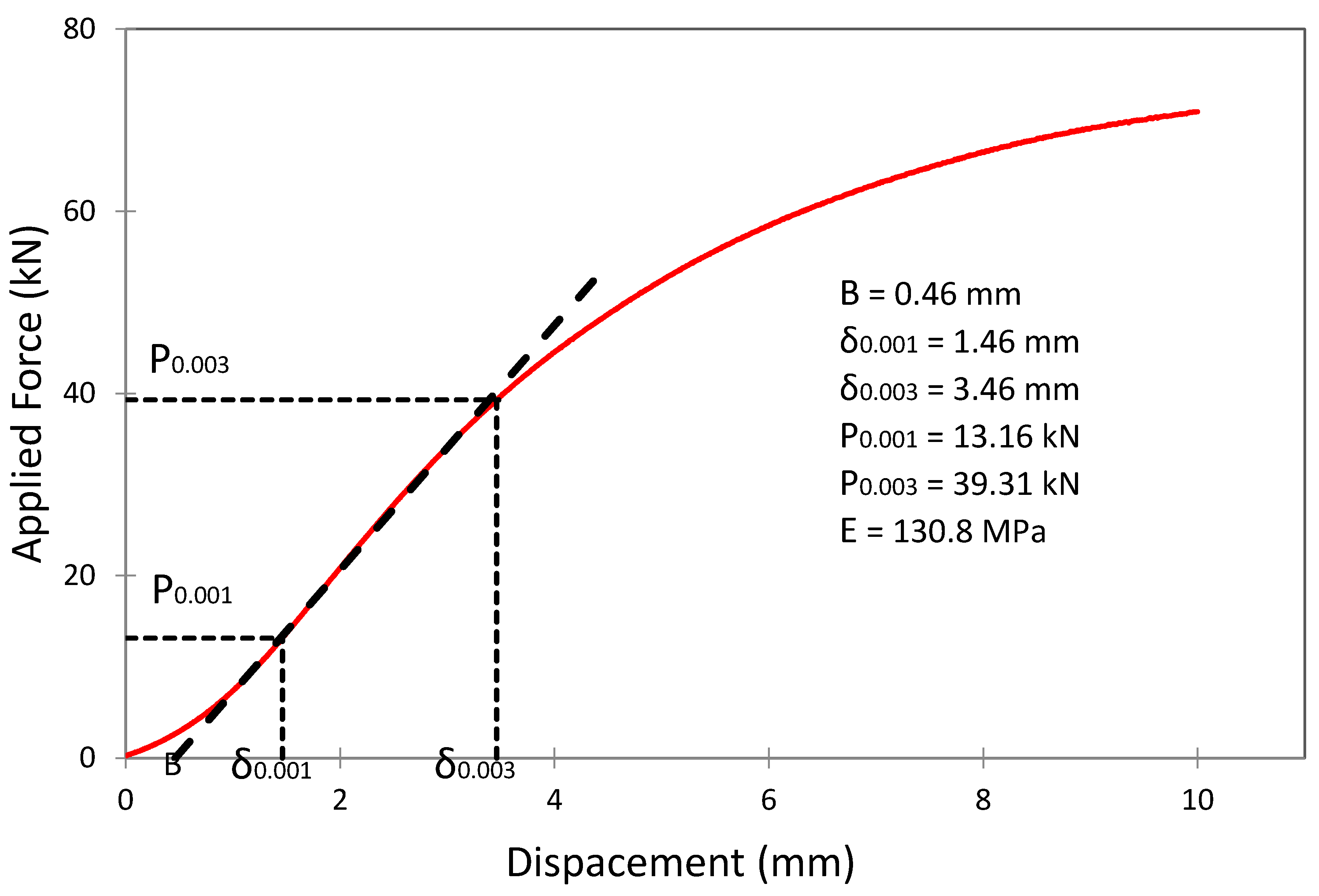
The compressive strength of the composite was also assessed through the flatwise compressive tests [35,36] of small sandwich cubes. Four specimens were tested to determine flatwise compressive strength and elastic modulus for the sandwich core’s structural design properties, using a universal testing machine and following the ASTM C365. Deformation data are obtained and, from a complete force versus deformation curve, it is possible to compute the compressive stress at any applied force (such as compressive stress at proportional limit force or compressive strength at the maximum force) and to compute the effective modulus of the core. Flatwise compressive tests were performed until the load–displacement curve indicated a collapsed structure, i.e., with significantly high deformation of specimens. The results, shown in Figure 7, indicate that the flatwise compressive behavior of the specimens is governed by rigid foam behavior, and the composite specimens show similar behavior to the foam specimens. That is, experiment results confirmed that, although a separation between the core and the skin is observed at the failure load, the possible local ruptures in the foam, due to the increased stress on the studs’ tips, do not influence the flatwise compressive behavior of the sandwich composite panel.
In Figure 7, E is the flatwise compressive modulus, P0.001 and P0.003 are forces, carried by test specimens at 0.1 % and 0.2% linear variable differential transformer (LVDT) deflection, respectively, B is the corrected zero displacement point (δ = 0.000) from which all displacements must be measured, and δs are corresponding LVDT deflections.
4. Flexural and Shear Behavior
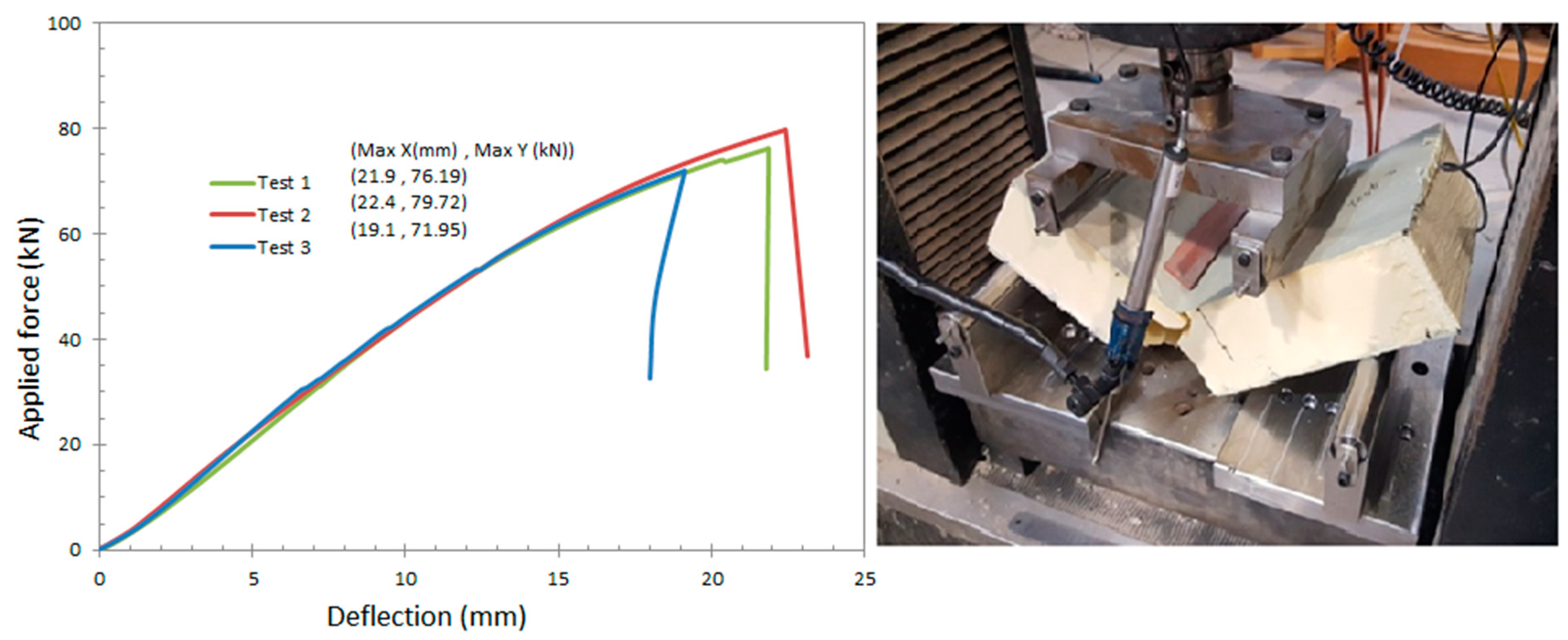
The flexural stiffness of sandwich beams/panels, which can be calculated using First-order Shear Deformation Theory (FSDT) [37,38,39,40], is used to estimate the shear stiffness of each sandwich beam type by fitting the results collected from four-point flexural tests. A perfect bond must be assumed to exist between the core and the facings. The bending stiffness can be computed accounting for the deflection components that are associated with bending and shear deformations [41,42]. This study examined the core shear properties of introduced PU infill-foam composite panels subjected to flexure in such a manner that the applied moments produce curvature of the sandwich facing planes. Also, in this regard, core shear ultimate stress, facing bending stress, transverse shear rigidity and core shear modulus of introduced sandwich panels are calculated based on ASTM C393/C393M [43] and ASTM D7250/D7250M [22] using six medium-scale sandwich specimens with 45 cm length, 20 cm width, and 10 cm as total thickness of composite section. This test method consists of subjecting a beam of sandwich construction to a bending moment normal to the plane of the sandwich. Forces versus deflection measurements are recorded. The applied force versus crosshead displacement and midspan deflection are shown in Figure 8, and transverse shear rigidity calculated based on ten load-deflection selective steps is shown in Table 2.
Effects of Cold Joints
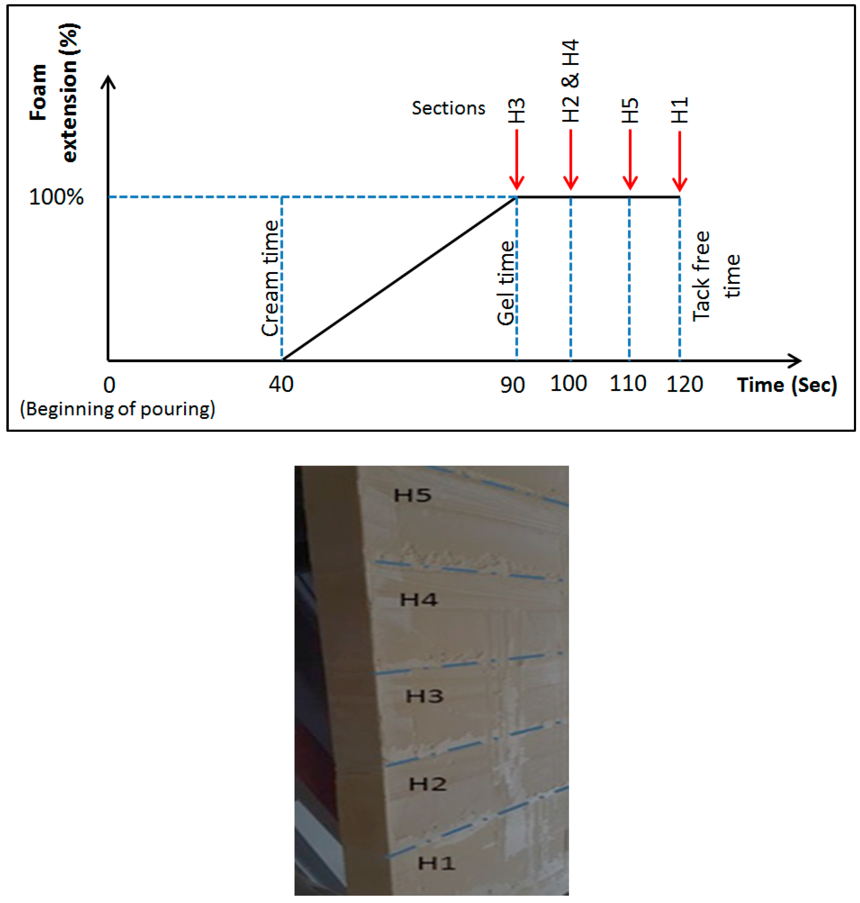
One of the most important construction problems of foam-made panels is cold joints, which are also known as seams. When the placing of foam in the panels is delayed or interrupted for some reasons, the foam that has already been placed starts to condense, producing a kind of construction joint (seam), called a cold joint, between it and newly placed foam. A seam is a plane under mixed materials, or a fold that is developed within the rising foam mass, which appears as a line on the foam surface or section [22]. Such joints between new and old portions of foam that are formed when the new foam is placed adjacent to the foam that has hardened or has started to harden, may have negative effects on the strength of rigid foam panel. Hence, attention must be paid to the position and direction of the joints, and the effects on structural behavior. For experimental investigation, three series of bending tests were carried out on two types of panelized specimens. Two types of 1500 × 1000 × 100 mm3 rigid PU panels were used: Type S (seamless) and type TS (with transverse seams) specimens, as shown in Figure 9. The expansion rate of this type of foam is 3.0, and the average weight of both types of panels is 29.0 kg.
A comparison between the results of the tests shows that casting at the end of gel time, instead of the end of tack free time, resulted in an 80% increase in the tensile strength of the seams. Also, casting at about 20 s before the end of tack free time (120th s), increased the tensile strength of the seams by 60%. The seamed section exhibited about 33.1% of the maximum tensile strength of an intact section. In addition, seamless panels showed a larger deflection capacity—20% more than that of TS panels.
5. Integrated Connections
Connections represent major challenges in the design of composite structures, mainly because they entail discontinuities in the geometry of the structure and material properties, and introduce high local stress concentrations. Despite some constructability complications, integrated connections could be a reliable solution. For the composite sections in this study, the connections between the panels are constructed by continued foam casting to achieve better integrity. The primary function of these connections is to guarantee the transfer of lateral (seismic and wind) loads between the composite panels, as well as between panels and roof in rapid-assembly postdisaster buildings. In addition, this connection accounts for restricting the rotation, i.e., the maximum deflections along the span. This is a significant factor because, in practice, the maximum allowable deformation is usually the governing factor in the design of lightweight composite sandwich panels.
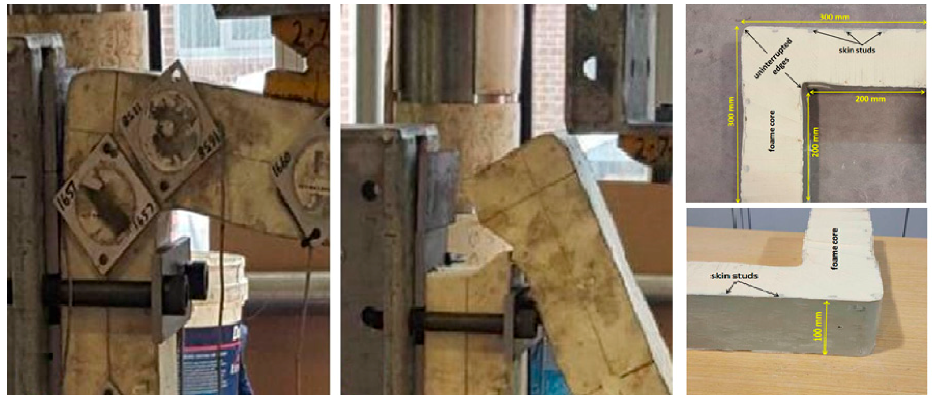
For the experimental investigation, six L-shape specimens, representing the connections between adjacent sandwich panels, are tested. In order to better study the composite performance and compare the results with noncomposite behavior, three of the specimens were made of composite sections, while three of them were foam-only sections; all of them were manufactured by a one-shot casting method in wooden formworks and were cut out of actual adjacent sandwich panels. The composite connections comprised of 2 mm thick 3D HDPE face sheets enclosing a 96 mm thick core of rigid PU foam. The test specimens were supported in a cantilever configuration test rig, and a point load was applied at 40 mm of the free edge, as illustrated in Figure 10.
As presented in Table 3, the overall mechanical response, stress distributions, failure modes, moment resistance, initial rotational stiffness, and rotational capacity of the connections were studied. The experimental test results indicated that in composite sections the bending ultimate strength increases by 25% compared to foam-only connections. The composite connections also show 2.2% greater rigidity and an increased rotational stiffness of 85%. With regard to the relative ultimate cantilever deflection, i.e., bending stiffness, composite connections presented a better performance by 12% in comparison with foam-only connections.
6. Concluding Remarks
A new foam-filled sandwich panel and its integrated connections were developed at the Centre for Infrastructure Engineering of Western Sydney University, as a rapid-assembly system for postdisaster housing and semipermanent accommodations. It is composed of 3D HDPE sheet skins with 2 mm thickness, and high-density PU foam-core with a total thickness as 100 mm, incorporated into a pneumatic fabric formwork. This paper investigated the structural performance of the panel and integrated connections with respect to the material properties, edgewise and flatwise compressive behavior, flexural and shear behavior, and the effect of cold joints (seams). The findings for each criterion indicate that the system fully complies with the relevant standards for semipermanent and temporary accommodations, and meets their requirements for postdisaster housing. In this regard, the following conclusions are achieved:
The used rigid foam is in accordance with ASTM E1730 Type 4, for which carrying out a thermal conductivity test is not required. A 100 mm thick layer of rigid PU provides a U-value of 0.04, which demonstrates high insulation performance of PU foam.
Barrateen was selected from the mentioned list of seven potential candidates as the best pneumatic formwork candidate for foam-filled structural composite panels. The type of lateral pressure of foam on this fabric formwork with thickness of 100 mm is hydrostatic.
The failure mode of specimens under the edgewise compression was local buckling (wrinkling) of the HDPE sheets between two edge studs, resulting in a local delamination and debonding between the face and core.
Results indicate that under flexure, the foam-core and skins displacement are in sync, which demonstrate well-integrated and ductile behavior of the introduced composite panel.
Further research on the constructional and architectural aspects, such as the integration of windows and doors, and onsite foam-casting methods are in progress.
Author Contributions
The paper, which is a part of S.N.’s PhD research project, was written through contributions of all authors. The experimental and numerical parts were carried out by S.N., under the B.S. and PS supervision. M.G. had contribution to the data collection and consulting.
Funding
This research received no external funding
Conflicts of Interest
The authors declare no conflict of interest.
References
- Goodyear, R.K.; Fabian, A. Housing in Auckland: Trends in Housing from the Census of Population and Dwellings 1991 to 2013; Statistics New Zealand: Wellington, New Zealand, 2014. [Google Scholar]
- Goodyear, R. Housing in Greater Christchurch after the Earthquakes: Trends in Housing from the Census of Population and Dwellings 1991–2013; Statistics New Zealand: Wellington, New Zealand, 2014. [Google Scholar]
- Abulnour, A.H. The post-disaster temporary dwelling: Fundamentals of provision, design and construction. HBRC J. 2014, 10, 10–24. [Google Scholar] [CrossRef]
- De Temmerman, N.; Brebbia, C.A. (Eds.) Mobile and Rapidly Assembled Structures IV; WIT Press: Ashurst, UK, 2014. [Google Scholar]
- Preston, S.J.; Bank, L.C. Portals to an architecture: Design of a temporary structure with paper tube arches. Constr. Build. Mater. 2012, 30, 657–666. [Google Scholar] [CrossRef]
- Australian Building Codes Board. National Construction Code Series/Australian Building Codes Board; Australian Building Codes Board: Canberra, Australia, 2011. [Google Scholar]
- Australian Building Codes Board. Temporary Structures Standard; Australian Building Codes Board: Canberra, Australia, 2015. [Google Scholar]
- Mira, L.A.; Thrall, A.P.; De Temmerman, N. Deployable scissor arch for transitional shelters. Autom. Constr. 2014, 43, 123–131. [Google Scholar] [CrossRef]
- Bouhaya, L.; Baverel, O.; Caron, J.-F. Optimization of gridshell bar orientation using a simplified genetic approach. Struct. Multidiscip. Optim. 2014, 50, 839–848. [Google Scholar] [CrossRef] [Green Version]
- Thrall, A.; Quaglia, C. Accordion shelters: A historical review of origami-like deployable shelters developed by the US military. Eng. Struct. 2014, 59, 686–692. [Google Scholar] [CrossRef]
- Sharafi, P.; Mortazavi, M.; Samali, B.; Ronagh, H. Interlocking system for enhancing the integrity of multi-storey modular buildings. Autom. Constr. 2018, 85, 263–272. [Google Scholar] [CrossRef]
- Sharafi, P.; Rashidi, M.; Mortazavi, M.; Samali, B.; Ronagh, H. Identification of Factors and Multi-Criteria Decision Analysis of the Level of Modularization in Building Construction. ASCE J. Archit. Eng. 2018, 24. [Google Scholar] [CrossRef]
- Sharafi, P.; Samali, B.; Ronagh, H.; Ghodrat, M. Automated spatial design of multi-story modular buildings using a unified matrix method. Autom. Constr. 2017, 82, 31–42. [Google Scholar] [CrossRef]
- Defonseka, C. Practical Guide to Flexible Polyurethane Foams; Smithers Rapra Technology: Shawbury, UK, 2013. [Google Scholar]
- Sharafi, P.; Teh, L.H.; Hadi, M.N.S. Conceptual design optimization of rectilinear building frames: A knapsack problem approach. Eng. Optim. 2015, 47, 1303–1323. [Google Scholar] [CrossRef]
- Allen, H.G.; Neal, B.G. Analysis and Design of Structural Sandwich Panels: The Commonwealth and International Library: Structures and Solid Body Mechanics Division; Elsevier Science: London, UK, 2013. [Google Scholar]
- Correia, J.R.; Garrido, M.; Gonilha, J.A.; Branco, F.A.; Reis, L.G. GFRP sandwich panels with PU foam and PP honeycomb cores for civil engineering structural applications: Effects of introducing strengthening ribs. Int. J. Struct. Integr. 2012, 3, 127–147. [Google Scholar] [CrossRef]
- Potluri, P.; Kusak, E.; Reddy, T.Y. Novel stitch-bonded sandwich composite structures. Compos. Struct. 2003, 59, 251–259. [Google Scholar] [CrossRef]
- Dawood, M.; Taylor, E.; Rizkalla, S. Two-way bending behavior of 3-D GFRP sandwich panels with through-thickness fiber insertions. Compos. Struct. 2010, 92, 950–963. [Google Scholar] [CrossRef]
- Company, D.P. How to Reduce Energy Costs in Your Building; Diane Publishing Company: Collingdale, PA, USA, 1983. [Google Scholar]
- Nemati, S.; Sharafi, P.; Samali, B.; Aliabadizadeh, Y.; Saadati, S. Non-reinforced foam filled modules for rapidly assembled post disaster housing. Int. J. GEOMATE 2018, 14, 151–161. [Google Scholar] [CrossRef]
- ASTM International. Standard Specification for Rigid Foam for Use in Structural Sandwich Panel Cores, ASTM-E1730; ASTM International: West Conshohocken, PA, USA, 2015.
- West, M.; Araya, R. Fabric formwork for concrete structures and architecture. In Proceedings of the International Conference on Textile Composites and Inflatable Structures, Stuttgart, Germany, 5–7 October 2009; CIMNE: Barcelona, Spain; pp. 5–7. [Google Scholar]
- Veenendaal, D.; West, M.; Block, P. History and overview of fabric formwork: Using fabrics for concrete casting. Struct. Concr. 2011, 12, 164–177. [Google Scholar] [CrossRef]
- Orr, M.J.; Darby, A.; Ibell, T.; Evernden, M. Fabric formwork for ultra high performance fibre reinforced concrete structures. In Proceedings of the FIB Symposium: Concrete Structures for Sustainable Community, Stockholm, Sweden, 11–14 June 2012. [Google Scholar]
- Orr, J.J.; Darby, A.P.; Ibell, T.J.; Evernden, M.; Otlet, M. Concrete structures using fabric formwork. Struct. Eng. 2011, 89, 20–26. [Google Scholar]
- West, M. The Fabric Formwork Book: Methods for Building New Architectural and Structural Forms in Concrete; Taylor & Francis: London, UK, 2016. [Google Scholar]
- Nemati, S.; Rashidi, M.; Samali, B. Decision making on the optimised choice of pneumatic formwork textile for foam-filled structural composite panels. Int. J. GEOMATE 2017, 13, 220–228. [Google Scholar] [CrossRef]
- ASTM International. Standard Test Method for Breaking Strength and Elongation of Textile Fabrics (Grab Test); ASTM D5034-09; ASTM International: West Conshohocken, PA, USA, 2017. [Google Scholar]
- McCarthy, M.J.; Dhir, R.K.; Caliskan, S.; Ashraf, M.K. Influence of self-compacting concrete on the lateral pressure on formwork. Proc. Inst. Civ. Eng. Struct. Build. 2012, 165, 127–138. [Google Scholar] [CrossRef]
- ASTM International. Standard Test Method for Determining Tensile Properties of Nonreinforced Polyethylene and Nonreinforced Flexible Polypropylene Geomembranes; ASTM-D6693; ASTM International: West Conshohocken, PA, USA, 2015. [Google Scholar]
- Sharafi, P.; Nemati, S.; Samali, B.; Mousavi, A.; Khakpour, S.; Aliabadizadeh, Y. Edgewise and flatwise compressive behaviour of foam-filled sandwich panels with 3-D high density polyethylene skins. Eng. Solid Mech. 2018, 6, 285–298. [Google Scholar] [CrossRef]
- ASTM International. Standard Test Method for Edgewise Compressive Strength of Sandwich Constructions; ASTM-C364; ASTM International: West Conshohocken, PA, USA, 2016. [Google Scholar]
- Abdi, B.; Azwan, S.; Abdullah, M.R.; Ayob, A.; Yahya, Y.; Xin, L. Flatwise compression and flexural behavior of foam core and polymer pin-reinforced foam core composite sandwich panels. Int. J. Mech. Sci. 2014, 88, 138–144. [Google Scholar] [CrossRef]
- Norouzi, H.; Rostamiyan, Y. Experimental and numerical study of flatwise compression behavior of carbon fiber composite sandwich panels with new lattice cores. Constr. Build. Mater. 2015, 100, 22–30. [Google Scholar] [CrossRef]
- Carlsson, L.A.; Kardomateas, G.A. Structural and Failure Mechanics of Sandwich Composites; Springer: Dordrecht, The Netherlands, 2011; Volume 121. [Google Scholar]
- Kaveh, A.; Sharafi, P. Nodal ordering for bandwidth reduction using ant system algorithm. Eng. Comput. 2009, 26, 313–323. [Google Scholar] [CrossRef]
- Kaveh, A.; Sharafi, P. A simple ant algorithm for profile optimization of sparse matrices. Asian J. Civ. Eng. (Build. Hous.) 2007, 9, 35–46. [Google Scholar]
- Kaveh, A.; Sharafi, P. Charged System Search Algorithm for Minimax and Minisum Facility Layout Problems. Asian J. Civ. Eng. 2011, 12, 703–718. [Google Scholar]
- Hayes, M.D. Structural Analysis of a Pultruded Composite Beam: Shear Stiffness Determination and Strength and Fatigue Life Predictions. Ph.D. Dissertation, Faculty of the Virginia Polytechnic Institute and State University, Blacksburg, VA, USA, November 2003. [Google Scholar]
- Sharafi, P.; Nemati, S.; Samali, B.; Bahmani, A.; Khakpour, S.; Aliabadizadeh, Y. Flexural and shear performance of an innovative foam-filled sandwich panel with 3-D high density polyethylene skins. Eng. Solid Mech. 2018, 6, 113–128. [Google Scholar] [CrossRef]
- ASTM International. Standard Test Method for Core Shear Properties of Sandwich Constructions by Beam Flexure; ASTM-C393/C393M; ASTM International: West Conshohocken, PA, USA, 2011. [Google Scholar]
- ASTM International. Standard Practice for Determining Sandwich Beam Flexural and Shear Stiffness; ASTM-D7250/D7250M; ASTM International: West Conshohocken, PA, USA, 2011. [Google Scholar]
Figure 1.
Sandwich with 3D high-density polyethylene (HDPE) skins, polyurethane (PU) foam-core, and pneumatic formwork.
Figure 1.
Sandwich with 3D high-density polyethylene (HDPE) skins, polyurethane (PU) foam-core, and pneumatic formwork.

Figure 2.
Results of the uniaxial load test on PU foam.

Figure 3.
Barrateen fabric tensile behavior in main and transverse directions.

Figure 4.
Effects of samples’ thickness and foam density on the maximum lateral deflection.

Figure 5.
HDPE tension test results in the lengthwise and crosswise directions.

Figure 6.
Test setup and design elastoplastic diagram of composite panel under edgewise compression, and the determination of module of elasticity
Figure 6.
Test setup and design elastoplastic diagram of composite panel under edgewise compression, and the determination of module of elasticity

Figure 7.
Description of flatwise compressive experiments calculation.

Figure 8.
Four-point quarter-span loading flexural test results.

Figure 9.
Casting schedule of seams at specimens with transverse seams (TS). Locations of transverse seams.
Figure 9.
Casting schedule of seams at specimens with transverse seams (TS). Locations of transverse seams.

Figure 10.
The ultimate deflection and the mechanism of collapse and dimensions of the connection.


Table 1.
Mechanical and manufacturing properties of the selected PU rigid foam.
| Mechanical Properties of the PU Foam | |||
|---|---|---|---|
| Density (kg/m3) | Compressive yield strength (MPa) | Tensile yield strength (MPa) | Shear yield strength (MPa) |
| 192 | 3.51 | 1.896 | 1.034 |
| Manufacturing properties of AUW763 | |||
| Cream time | Gel time | Track free time | Free rise density |
| 35-40 s | 94 ± 4 s | 115 ± 5 s | 280–300 kg/m3 |
Table 2.
The least maximum applied forces and their related midspan deflections.
| Tests | 4-Point Quarter | Span Loading | 3-Point Mid Span | Loading |
|---|---|---|---|---|
| Pmax (kN) | ∆midspan (mm) | Pmax (kN) | ∆midspan (mm) | |
| Specimen 1 | 76.19 | 21.9 | 56.23 | 24.9 |
| Specimen 2 | 79.72 | 22.4 | 52.54 (minimum) | 23.8 |
| Specimen 3 | 71.95 (minimum) | 19.1 | 53.98 | 24.2 |
| Average | 75.95 | 21.1 | 54.25 | 24.3 |
| Standard deviation | 3.89 | 1.8 | 1.86 | 0.56 |
| CV (%) | 5.12 | 8.42 | 3.5 | 2.3 |
Table 3.
Summary of the experimental carried tests for both simple and composite systems.
| Test Details | Ultimate Load (N) | Ultimate Displacement (mm) | Ultimate Rotation (Degree) | |
|---|---|---|---|---|
| Foam-only Specimens | Specimen 1 | 7991 | 42.0 | 5.0 |
| Specimen 2 | 7172 | 44.0 | 6.0 | |
| Specimen 3 | 7870 | 52.0 | 8.0 | |
| Average | 7678 | 46.0 | 6.3 | |
| CV (%) | 5.8 | 11.5 | 1.8 | |
| Composite Specimens | Specimen 1 | 9299 | 44.0 | 4.0 |
| Specimen 2 | 9602 | 41.0 | 6.0 | |
| Specimen 3 | 9926 | 38.0 | 3.0 | |
| Average | 9609 | 41.0 | 4.3 | |
| CV (%) | 3.3 | 7.3 | 1.8 | |
© 2018 by the authors. Licensee MDPI, Basel, Switzerland. This article is an open access article distributed under the terms and conditions of the Creative Commons Attribution (CC BY) license (http://creativecommons.org/licenses/by/4.0/).
Share and Cite
MDPI and ACS Style
Sharafi, P.; Nemati, S.; Samali, B.; Ghodrat, M. Development of an Innovative Modular Foam-Filled Panelized System for Rapidly Assembled Postdisaster Housing. Buildings 2018, 8, 97. https://doi.org/10.3390/buildings8080097
AMA Style
Sharafi P, Nemati S, Samali B, Ghodrat M. Development of an Innovative Modular Foam-Filled Panelized System for Rapidly Assembled Postdisaster Housing. Buildings. 2018; 8(8):97. https://doi.org/10.3390/buildings8080097
Chicago/Turabian StyleSharafi, P., S. Nemati, B. Samali, and M. Ghodrat. 2018. "Development of an Innovative Modular Foam-Filled Panelized System for Rapidly Assembled Postdisaster Housing" Buildings 8, no. 8: 97. https://doi.org/10.3390/buildings8080097
Note that from the first issue of 2016, this journal uses article numbers instead of page numbers. See further details here.