Feasibility Study of Mass-Timber Cores for the UBC Tall Wood Building


Wood Engineering, University of Northern British Columbia, Prince George, BC V2N 4Z9, Canada
*
Author to whom correspondence should be addressed.
Buildings 2018, 8(8), 98; https://doi.org/10.3390/buildings8080098
Submission received: 28 June 2018
/
Revised: 25 July 2018
/
Accepted: 25 July 2018
/
Published: 1 August 2018
(This article belongs to the Special Issue Advances in Mass Timber and Timber Hybrid Lateral Load Resisting Systems)
Abstract
:The UBC Brock Commons building in Vancouver, which comprises of 18 stories and stands 53 m in height, was at the time of completion in 2016 the world’s tallest hybrid wood-based building. The building’s 17 stories of mass-timber superstructure, carrying all gravity loads, rest on a concrete podium with two concrete cores that act as both the wind and seismic lateral load-resisting systems. Whereas the construction of the concrete cores took fourteen weeks in time, the mass-timber superstructure took only ten weeks from initiation to completion. A substantial reduction in the project timeline could have been achieved if mass-timber had been used for the cores, leading to a further reduction of the building’s environmental footprint and potential cost savings. The objective of this research was to evaluate the possibility of designing the UBC Brock Commons building using mass-timber cores. The results from a validated numerical structural model indicate that applying a series of structural adjustments, that is, configuration and thickness of cores, solutions with mass-timber cores can meet the seismic and wind performance criteria as per the current National Building Code of Canada. Specifically, the findings suggest the adoption of laminated-veneer lumber cores with supplementary ‘C-shaped’ walls to reduce torsion and optimize section’s mechanical properties. Furthermore, a life cycle analysis showed the environmental benefit of these all-wood solutions.
1. Introduction
While wood, as the most important renewable structural material, has always been an essential part of the built environment [1], the importance of using sustainable construction materials is increasing with the rising global demand for housing and an increase in the understanding of the impacts our built environment has on climate change. Multiple studies, for example, [2,3], demonstrated the favorable environmental balance when using wood or its engineered wood product derivatives as building material when compared to concrete or steel. As a consequence of the increasing push towards lower carbon footprint buildings, there is a growing effort worldwide to develop solutions for the key strategic market of mid-rise buildings and to prepare solutions for high-rise buildings.
Two recent publications, ‘Technical Guide for the Design and Construction of Tall Wood Buildings in Canada’ [4] and ‘Use of Timber in Tall Multi-Story Buildings’ [5] are testament to the renewed interest in tall timber buildings. This development has also been labelled a ‘Renaissance,’ as the construction of tall (up to nine stories) post and beam timber buildings with exterior by walls made of un-reinforced brick was common practice in North America at the beginning of the 20th century but fell out of favor in the decades that followed [6]. Changes to the building codes around the world, mostly driven large fire disasters, limited the height of timber buildings first to three or then to four stories. Only after decades of research and a comprehensive consultation process were Building Codes changed, first to permit six-story light-frame wood buildings [7] and more recently 12-story mass-timber buildings [8].
During the last few decades, several innovative materials, connectors and systems have been introduced that have contributed to the tall-timber renaissance. At the material level, the introduction of engineered mass-timber products which can be used for floors or walls such as Laminated Veneer Lumber (LVL) and Cross-laminated Timber (CLT) changed the industry significantly [9]. Multiple studies also provided guidance for designing CLT lateral load-resisting systems (LLRS) [10,11,12,13]. At the connector level, Self-tapping screws (STS) and glued-connections [14,15,16] provide alternative methods that go beyond the limitations of traditional dowel-type connectors.
At the system level, novel hybrid solutions such as pre-stressed self-centering systems [17,18,19], steel moment frames with CLT infill panels [20], mass-timber balloon-frames with steel links [21,22], the timber-concrete jointed-frame concept [23] and timber-concrete composite floors [24] or timber-steel hybrid systems [25,26,27] are attracting more attention due to their advantage in solving design problems. Construction typologies with prefabricated elements made of engineered wood products are preferred since the process can be quickly industrialized and the on-site mounting time can be reduced; prefabricated elements can also be equipped with additional layers to complete the building envelope, including services and finishing [28].
Over the last decade, tall-timber buildings have been erected around world; examples include the ‘Stadthaus’, a nine-story residential building completed in 2009 in London, the ‘LifeCycle Tower ONE’, an eight-story building with a concrete central core with glulam columns and hybrid slabs in Dornbirn, Austria, ‘Forte’, a 32 m-tall ten-story CLT building in Melbourne, Australia, with only the first floor and foundation made of concrete, ‘TREET’, a fourteen-story building in Bergen, Norway, with a height of 45 m and the 29 m-tall ‘Wood Innovation and Design Centre’ in Prince-George, Canada [29].
2. UBC Tall Wood Building
2.1. Background
The ‘Tall Wood Building Demonstration Initiative’, launched in 2013 by Natural Resource Canada was implemented ‘To test the use of wood in larger and taller wood buildings’ [28]. A call for expressions of interest to design and construct high-rise wood demonstration projects was posted with ‘The aim to link new scientific advances and data with technical expertise to showcase the application, practicality and environmental benefits of innovative wood-based structural solutions’ [28]. The requirement was to use mass-timber products in structures of at least ten stories tall.
The University of British Columbia was successful with its proposal to design and build a wood-based student residence building, herein referred to as the UBC Tall Wood Building (TWB). The 18-story building has a typical inter-story height of 2.8 m, a total building height of 58.5 m to the top of the elevator parapet, a story floor area of 840 m2 (15 m × 56 m) and provides 404 beds which are distributed as single-bed studios or four-bed units located on floors 2–18. Due to the perceived increased fire risk, marketing a tall wood building to students and their families was seen as a challenge that was mitigated by a targeted media strategy [28].
Upon completion, ‘The project proved to be cost-competitive in the local marketplace, which was largely achieved by an integrated design team, real-time input from trades and structural discipline’ [28]. In an effort to better understand the unique behavior of this building moving forward, the structure is being monitored with accelerometers, moisture meters and string potentiometers [30].
2.2. Building Regulation
The building belongs to Group C (residential) major occupancy which according to the governing British Columbia Building Code [7] could only be of combustible construction if they are no more than six stories and 18 m high and have a maximum area of 1200 m2. For buildings to exceed these constraints, they must be of non-combustible construction, have floor assemblies with a fire-resistance rating (FRR) no less than 2 h, be sprinklered throughout and use load-bearing elements that have a FRR no less than the supported assembly.
Given the code noncompliance, a performance-based approach was followed in the form of a Site-Specific Regulation (SSR) developed by the Authorities Having Jurisdiction (AHJ). In this case, the AHJ was the Province of British Columbia’s Building Standards and Safety Branch (BSSB), authorized under the Building Standards and Safety Act. Obtaining approval was a challenge for this project, specifically considering the tight time-line. Many design decisions were made to keep the project simple and ensure its approval [28]. A key consideration was to get the AHJ involved and communicate the intent of the design solutions. Given the noncompliance with the code, the SSR was developed by the AHJs. The outcome of the SSR was a regulation that is only applicable to the site that is concerned by the project. Therefore, while setting an important precedent, this specific SSR does not allow for future tall wood buildings of similar design to be approved without a new process.
The SSR process involved both a structural review expert panel and a fire safety expert panel. The two panels met twice, with the final presentation being made by the design team in June 2015 to get approval by September 2015. During the structural review, feedback was sought from the expert panels on whether the proposed design was too conservative, thus adding unnecessary cost to the project and which seismic load assumption to apply [28]. To mitigate the fire safety concern, it was decided to fully equip the building with sprinklers, including a reserve water tank to ensure sprinklers will work if the main water line is interrupted. Additionally, all structural timber components were encapsulated in gypsum wall-boards to comply with a 2 h FRR.
2.3. Structural System
A key driver in developing and detailing the design was the use of tested solutions, which were code compliant and/or certified by product approvals. In other words, while the project itself was innovative, its components were designed for simplicity and standard-compliance use. A full-scale two-story mock-up, consisting of a core wall and three-by-three bays, allowed the project team to test the constructability of the system, refine the chosen products and processes and to validate some decisions, for example, the connection details and the construction of the prefabricated envelope panels [31].
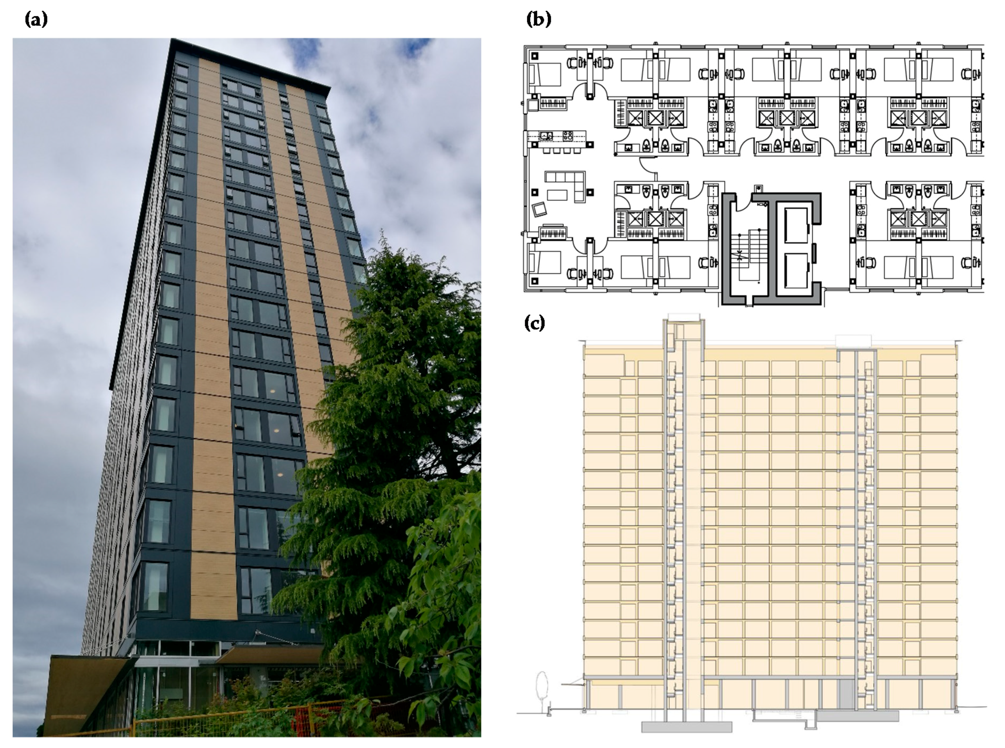
The building’s structural system is a hybrid configuration (Figure 1) and is supported by 2.8 × 2.8 × 0.7 m thick reinforced concrete spread footings. Each core is supported by a 1.5 m raft slab that includes soil anchors and a 250 mm thick wall on a strip footing is located at the perimeter of the building’s foundation. The second floor, also made of concrete, acts as a transfer slab. The building’s superstructure comprises of the concrete podium and cores, the mass timber columns and floors, as well as the steel roof structure. The decision to go to a hybrid structural solution was taken early on in the project and was paramount in setting the direction for the project approval. The concrete podium houses the ground level amenities and provides high clearances and large spans in the public spaces on the first floor of the building. The 2nd floor acts as a transfer slab and takes the gravity load of the 17 stories above and allows the ground level structural grid to be independent from the grid of the wood structure. The 450 mm thick cast-in-place reinforced concrete cores provide the rigidity to support lateral forces on the building as well as the vertical circulation, including the stairs and elevator shafts [28,32].
The primary framing consists of mass-timber columns (Parallam for the highest loaded zones and Glulam for the remainder) and a perimeter beam to support the building envelope. The typical column cross sections are 265 × 265 mm and 265 × 215 mm on the upper levels with the typical structural bay measuring 4 × 2.85 m. Although there were only four different panel lengths, most panels on a single floor were unique due to the configuration of multiple openings. The secondary framing consists of continuous CLT panels, eliminating the need for beams and increasing the speed of erection. One disadvantage of this solution was the fact that the columns had to be braced during construction, as they were free-standing until the top panel was in place [28,32].
The mass timber superstructure resulted in a building that is 7648 tons lighter than an equivalent concrete building, therefore requiring smaller footings and resulting in lower costs. However, in a high seismic zone such as Vancouver, this decrease in mass also resulted in lower resistance to overturning when compared to an equivalent concrete structure [32].
2.4. Connection Design
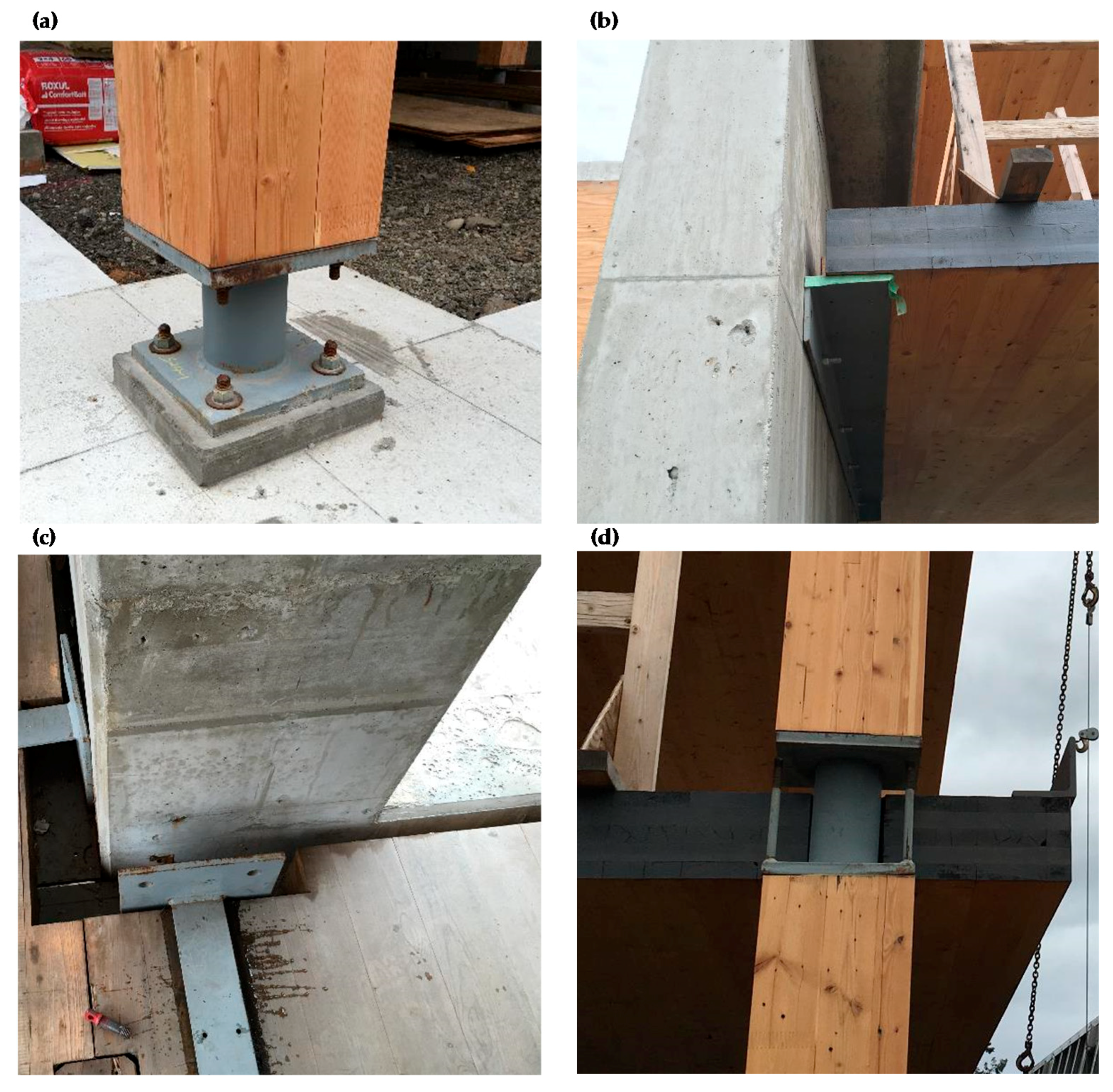
Some of the key challenges in designing the second level slab were the different reactions to lateral loads of the concrete and the wood components, the anchor bolt placement for the columns during construction and the coordination of the electrical and mechanical (e.g., water-lines) installations through the floors. The connections between the concrete slab and the wood columns are shown in Figure 2a. The connections between the CLT floor panels and the concrete core are another important interface, as it needs to account for the vertical shear transfer and the differential settlement between the wood and concrete structure, which was expected to be approx. 50 mm. The solution was a steel ledger angle (203 × 152 × 13 LLH) welded to a 300 mm wide embedded plate cast in the core at every 1500 mm and then screwed to the CLT panels, (see Figure 2b [28,32]). The CLT floor panels were also connected at their edges using 140 mm × 25 mm cross-section plywood splines.
The drag strap to core connection ensures that lateral loads are transferred to the core. The straps are 100 mm wide steel plates which vary in thickness between 6.4 mm and 12.5 mm depending on the floor level of the building and between 1.5 m and 7.2 m in length depending on orientation. The drag straps are welded to faceplates that are anchored to the core, as shown in Figure 2c. The connections between columns and panels represented a challenge as the interface simultaneously had to effectively transfer both the vertical loads as well as support the panel shear loads (column to column and column to panel). These connections also allow the panels to act as a diaphragm to transfer lateral loads to the cores, limit the transmission of vibrations and provide a 2 h FRR. A welded HSS and steel plate assembly, as illustrated in Figure 2d, was chosen since it fulfills all of these requirements. Slightly oversized shims were used as needed to level the assembly and account for differential settlement, due to elastic shortening and shrinkage of the columns; and a 40 mm concrete topping fills the space between the columns and the CLT panels [28,32].
2.5. Objectives
The construction process of the TWB displayed a significant difference in duration between the cores and superstructure. The construction of the cast-in-place reinforced concrete cores took fourteen weeks whereas the mass-timber superstructure, including the envelope, took just ten weeks. The construction of the TWB with mass-timber cores could have further decreased the schedule leading to cost savings and environmental benefits.
Based on this idea, the research team was motivated to investigate the structural feasibility of the TWB with mass-timber cores instead of concrete cores. Specifically, the impact of substituting the core material from concrete to timber on the lateral response of the building was evaluated based on dynamic analyses. As a secondary objective, a life cycle analysis was conducted to evaluate the environmental benefit of these all-wood solutions.
3. Numerical Investigation
3.1. Design Options
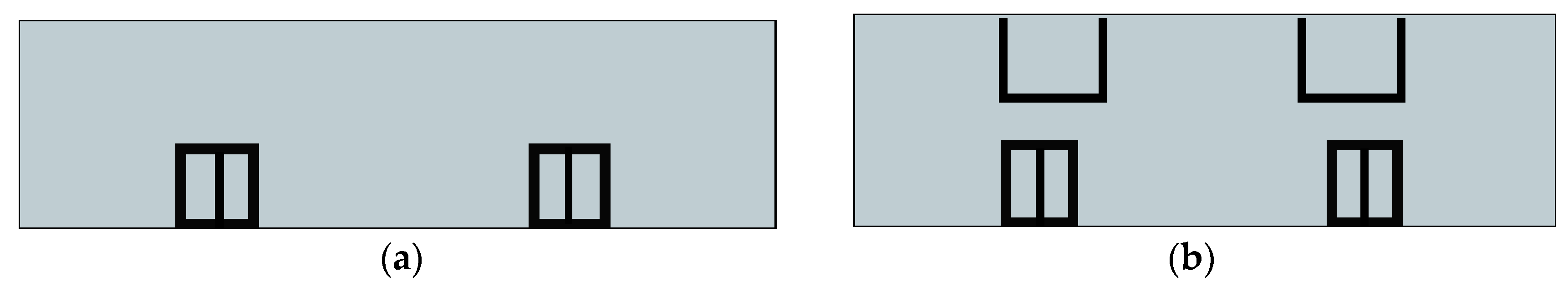
The architectural plan arrangement as shown in Figure 1b and the geometry of the original building were maintained. The LLRS was designed considering two engineered wood products, CLT and LVL. In addition to the original solution with only cores as LLRS, herein layout 1 (Figure 3a), a supplemental option with cores and mirrored ‘C-shaped’ walls, herein layout 2 (Figure 3b), was considered in the analyses in order to provide additional lateral strength and stiffness to the building.
For comparison purposes, the as-built solution with concrete cores has also been included and was labeled D-1. For layout 1, four alternative design solutions were studied: D-2 and D-3 considering CLT cores and D-4 and D-5 with LVL cores. Analogously, for layout 2, in design solutions labeled D-6 and D-7 CLT- and LVL-based LLRS were modeled, respectively.
For D-2 and D-4, the cores were assumed to be monolithic mass-timber walls with completely rigid connections between individual panels. This assumption, however, is unrealistic from a practical point of view, even if using a large number of fasteners with high stiffness; and connection deformability represents a large amount in the deformation of the whole structure [33,34,35]. Therefore, for D-3, D-5, D-6 and D-7, a pragmatic approach was adopted where the stiffness properties of the cores were reduced by 50% to account for the joints distributed along the borders of the timber panels and through the height of the wall. Such an approach is frequently applied in practice for preliminary design without prior knowledge of the exact connector layouts (Personal conversation with Erik Karsh, Principal Equilibrium Consulting, Vancouver, BC, Canada). This simplified assumption of 50% reduction in core stiffness was taken as the lower bound while the monolithic core was taken as an upper bound for this case study on substituting the concrete cores in the TWB with mass-timber.
For D-1, which reflects the actual TWB design, each concrete core was considered as a coupled ductile shear walls system in the X-direction and partially-coupled ductile shear walls system in the Y-direction, the latter to account for large openings. Therefore, ductility, Rd and over-strength, Ro, factors were taken as 3.5 and 1.6 in the X-direction and 3.5 and 1.7 in the Y-direction, respectively, in accordance with the National Building Code of Canada (NBCC) [36]. For solutions D-2 and D-4 which were monolithic and for the remaining solutions D-3 and D-5–D-7, for which details and behavior of the connections had not been established, conservative values of 1.0 and 1.3 were assumed for Rd and Ro, respectively, as recommended by CSA 086-14 [37] for CLT systems other than platform-framing with limited aspect ratios of the panels and specific ductility requirements for the connections.
3.2. Material Parameters
35 MPa concrete [38], 9-ply 315 mm thick E1M5 CLT panels [39] and 445 mm thick LVL panels [40] (five layers of 89 mm) were considered for the cores and additional walls, with mechanical characteristics provided by the manufacturers. Main materials properties considered in this study are reported in Table 1, where E1 and E2 are modulus of elasticity in the 1- and 2-directions, respectively and G23, G13 and G12 are shear modulus respect to the 2–3, 1–3 and 1–2 directions. As a conservative design assumption, E2 of CLT panels was assumed equal to zero to account for the manufacturing process in North America, in which, in forming the CLT panels, boards are not glued at their edges.
3.3. Design Requirements
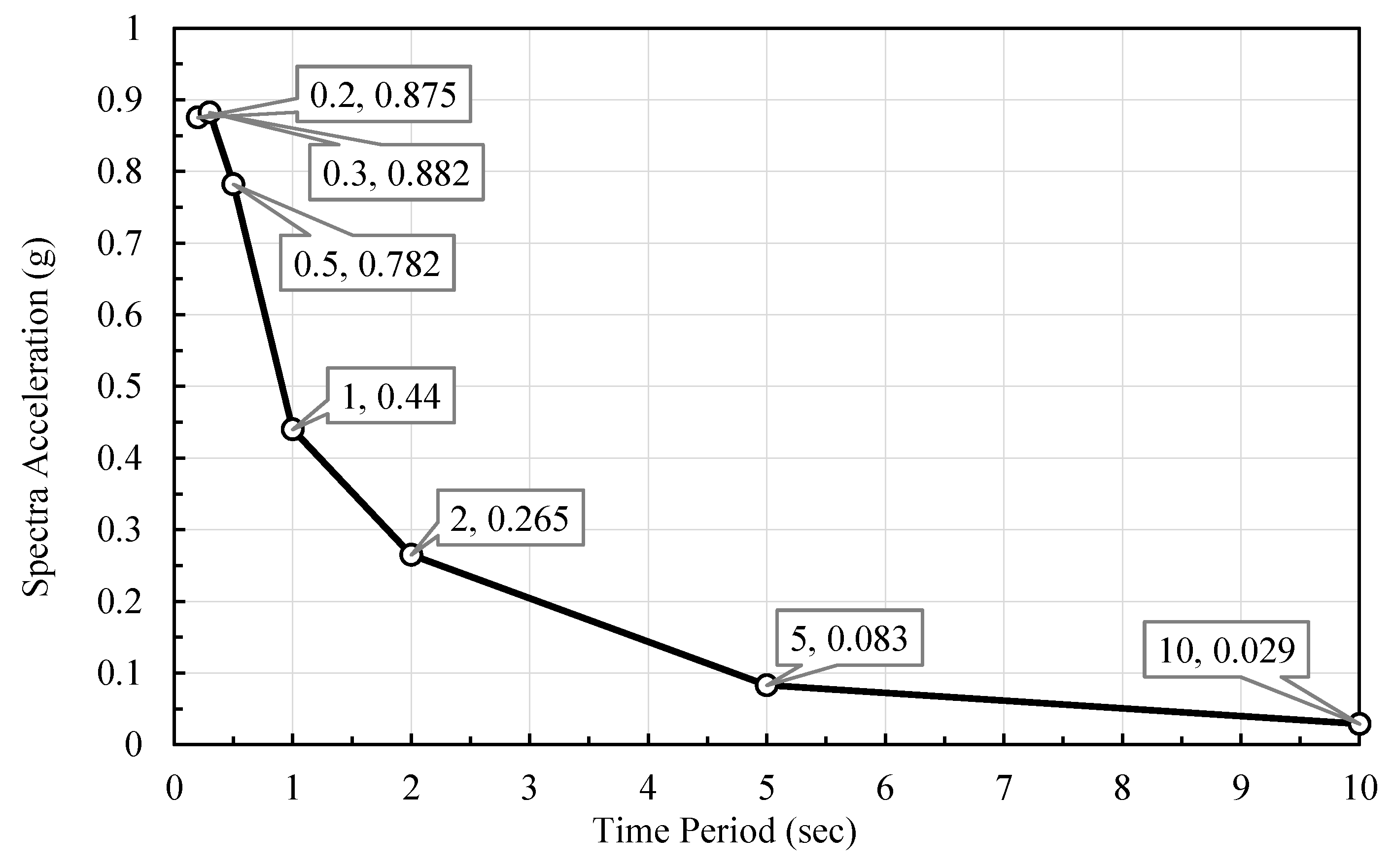
Design options D-1–D-7 were studied considering structural performance as prescribed by NBCC [36]. Inter-story drift limits of 2.5% and 0.2% (1/500) were considered a requirement for seismic and wind design, respectively, with an important factor of 1 associated to the building. To evaluate the seismic load in both directions of the building, the uniform seismic hazard spectrum (UHS) from the Geological Survey of Canada [41] (c.f. Figure 4) was used based on the TWB’s location and assuming site class C. For the wind design, the reference velocity pressure for Vancouver provided in NBCC [36] was considered, along with an important factor of 0.75 and an exposure factor as per open terrain sites.
3.4. Numerical Model
A model was developed using the commercial software RFEM [42] reflecting the original geometry and assumptions adopted by the structural designers of the building [32]. Appropriate boundary conditions and types of elements were used to describe the response of the structural members of the building. Fixed end-node restraints were adopted for concrete columns, slabs and cores, whereas timber elements were assumed pinned at their ends.
Columns were modelled using 1-D linear elements, while slabs and cores were modelled with 2-D plate elements (Figure 5). The material stress-strain law was assumed isotropic linear elastic-plastic for concrete, equivalent isotropic linear elastic for wood in the columns since they were subjected to axial loading only and orthotropic linear elastic for wood in both solutions with CLT and LVL panels. The layered structure of CLT panels was modelled using the RF-laminate add-on module to account for their crossed directions.
3.5. Analysis
Modal Analysis (MA), Linear Dynamic Response Spectrum Analysis (LDRSA) and Dynamic Wind Analysis (DWA) were carried out for design options D1–D7.
The MA was executed to determine the natural mode shapes and free vibration frequencies of the building at different variations of the LLRS. Seismic mass used in determining mode shapes considered a load combination of 1.0·Dead + 0.5·Live + 0.25·Snow. The same load combination was used to evaluate the initial stiffness of the structure when the induced axial forces in all the structural members were also considered in the model. To limit computation times, only the first ten modes of vibrations were assessed and used in the analyses.
The LDRSA were performed using the UHS response spectra as defined in Figure 4. Equivalent loads were generated based on each mode of vibration. The resulting loads were applied to the diaphragms assuming a ±0.1D eccentricity as per NBCC [36], where D represented the plan dimension of the building perpendicular to the direction of acting load. The complete quadratic combination of the resulting modes of vibration with a 5% damping ratio was used to assess the final lateral loading of the building. Base shear and lateral deflection expressed in terms of inter-story drift values were derived for each of the design options from D-1 to D-7.
The DWA was executed following the procedure set out in the NBCC [36]. Windward, leeward and side pressures were applied to each floor, with the analysis considering the wind acting separately along each principal horizontal axis of the building. The pressure was considered as a uniform line load acting along the perimeter of any given floor, with only the main combination that included 100% of the wind load acting on the building being considered in the analyses.
4. Results and Discussion
4.1. Dynamic Elastic Behavior
The results of the MA are expressed in the form of periods and mass-participation ratios given in respect to the total seismic mass. Specifically, Table 2 reports the 1st (T1), 2nd (T2) and 3rd (T3) periods of vibration of the relative mode as they correspond to the translational modes along the X-direction, Y-direction and torsional mode, respectively. The sum of the mass-participation ratios considering the first ten modes of vibration for both the X-(∑mx) and Y-direction (∑my) are also included as well as the first three periods of vibration calculated by the designers of the TWB (D-1*) (Personal conversation with Robert Jackson, Project Engineer Fast + Epp, Vancouver, BC, Canada). Figure 6 illustrates the first three modes shapes exemplarily for the design D-1 with the first mode being translational in X-direction, the second mode translational in Y-direction and the third mode torsional, confirming the impact of the stiffness eccentricity on the behaviour of the LLRS.
4.2. Lateral Response
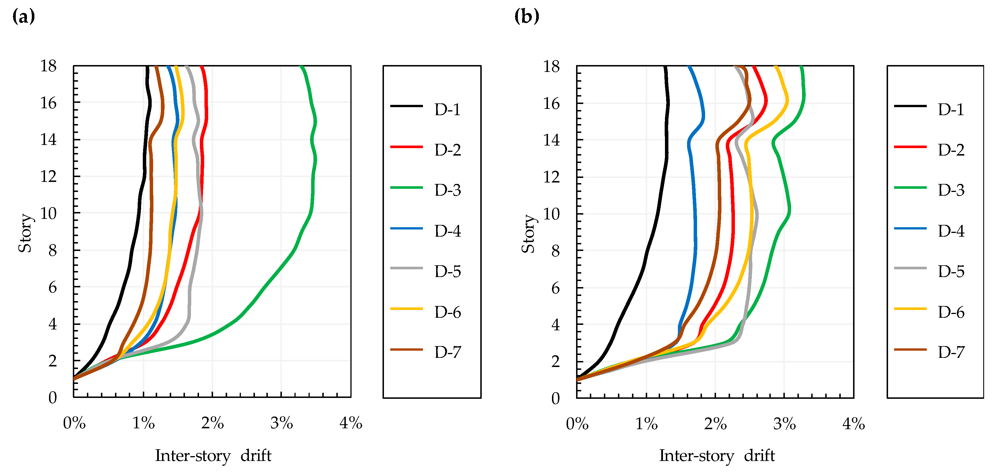
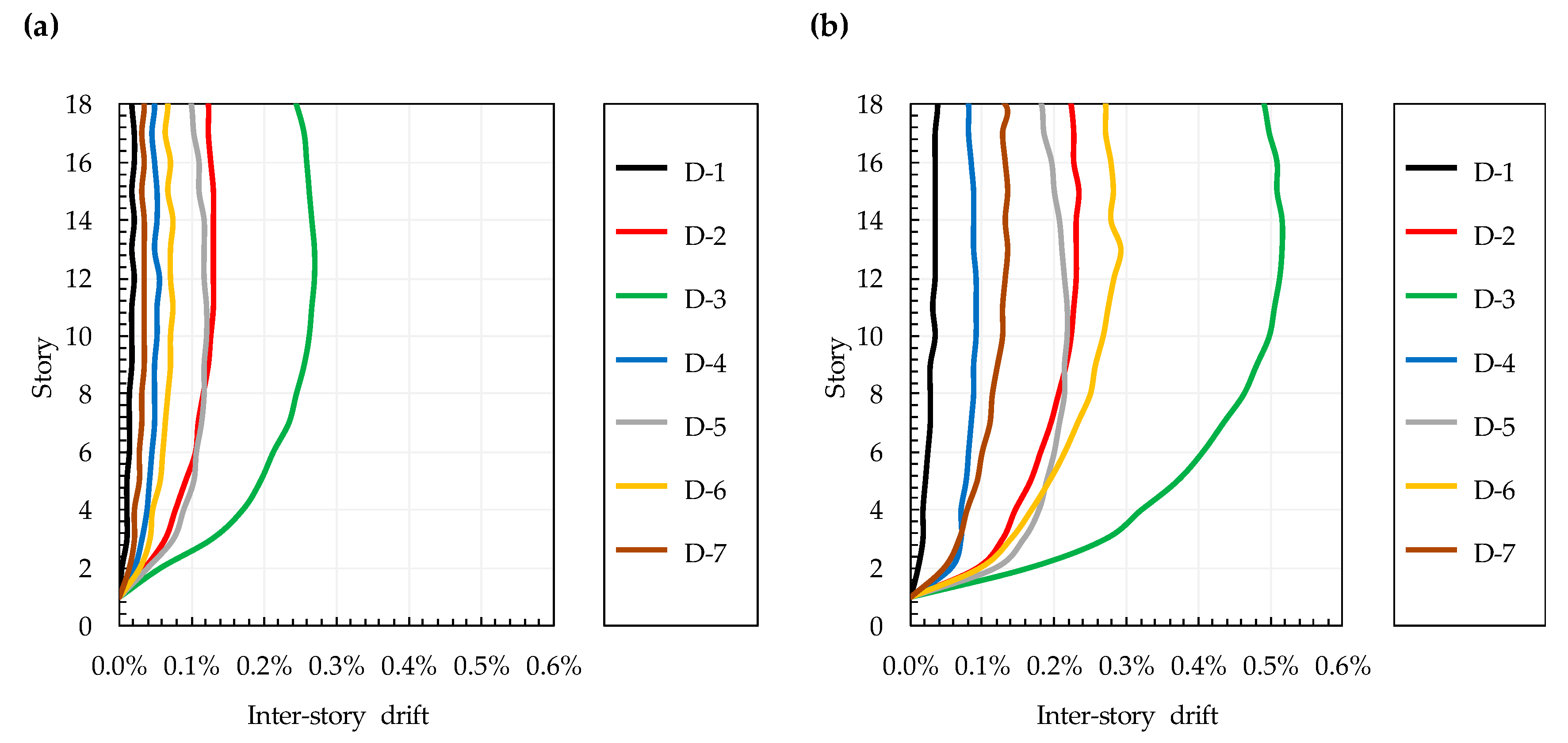
Results from the LDRSA, listed in Table 3, are expressed in terms of base shear (Vb,X and Vb,Y), elastic values and design values within brackets and maximum inter-story drift values (θmax,X and θmax,Y). The inter-story drift profiles for both the X- and Y-directions under seismic loads are shown in Figure 7. The resulting base shear and inter-story drift under winds loads are included in Table 4, while Figure 8 shows the matching inter-store drift profiles for the X- and Y-directions.
4.3. Discussion
A satisfactory match between the building’s first, second and third periods of vibration obtained by the designers of the TWB (D-1*) and from the MA using the numerical model presented herein (D-1) was found, see Table 2. Therefore, the numerical model developed herein was considered acceptable for the scope of this work.
From the MA, except for D-5 in the Y-direction, the results did not satisfy the 90% modal participation rate requirement of NBCC [36]. However, the modal mass participation rate in case of timber-based LLRS (D-2–D-7) ranged between 83% and 89% and only option D-1 with concrete LLRS was observed particularly distant from the 90% limit with ∑mx = 77% and ∑my = 61% mass participations. Therefore, the analysis did not consider all significant modes of vibration. However, as per the stated objective of this study, the results were used for comparative purposes only. The difficulty in reaching the limit considering the first ten modes provided a rough measure of the structural irregularity in elevation. An improvement was shown by adopting timber-based LLRS instead of concrete, demonstrated by comparing D-1 with the worst case scenario of D-6, with ∑mx = 83% and ∑my = 83% mass participations respectively.
The periods of the building for the CLT LLRS solutions D-2, D-3 and D-6 increased to values beyond 2 s, in some cases significantly larger than those of D-1. Periods also diverged from the target period obtained by dividing the number of stories by ten, which is 1.8 s for the TWB building. With periods as long as 6 s, as per direction X of D-3, high sensibility to wind dynamics, soil-structure interaction and second-order effects are expected, along with other design issues commonly associated with suspension bridges. Besides, with respect to all CLT solutions, independent of the mode and direction of vibration, as well as layout considered, a sensitivity for higher modes and damage under low to moderate earthquakes could be expected. The increase of periods in case of LVL LLRS solutions was also notable, however, peak values were much lower compared to the CLT solutions. The most reasonable increases of T1, T2 and T3 compared to D-1 were observed for D-7 with 40%, 73% and 77%, respectively.
The replacement in the LLRS of concrete with mass-timber increased the lateral flexibility of the building, which, together with the associated decreased of mass, reduced the acceleration induced by earthquakes. As a result, there was a reduction of the elastic base shear, particularly evident in D-3 which had 32% reduction with respect to D-1. Despite this advantage, due to the conservative approach adopted for the reduction factors Ro and Rd, the design base shear was found on average twice as high than that of the concrete system leading to the need for stronger base anchorages.
From the maximum inter-story drift in both directions, the change from concrete to timber LLRS increased the lateral deflection of the building, especially along the Y-direction where the large core openings significantly reduced the stiffness of the structure. Examining the maximum seismic inter-story drifts compared to the original design option D-1, the average increase was 76% and 104%, for the X- and Y-direction, respectively. Focusing on CLT LLRS, little benefit was observed by changing the layout, for example, comparing D-3 with D-6, which gave θmax of 3.2% and 2.9%, respectively. Besides, the CLT panels used were already the thickest commercially available in Canada. These findings suggest that additional shear walls are needed when CLT is to be used as core material for a tall building.
LVL LLRS provided a more suitable response since panels with higher in-plane stiffness are available. Only D-4 and D-7 provided code compliance; in the best-case scenario, D-4, structural performance was found comparable to that of D-1. Similar to the CLT models, however, the adoption of additional ‘C-shaped’ walls only led to small improvements of the building performance; in fact, moving from D-5 to D-7 only decreased maximum seismic inter-story drifts from 2.6% to 2.5%. As a result, to reduce the drift caused by earthquakes, the adoption of additional walls proved ineffective to reduce inter-story drift, however torsional sensitivity of the building when loaded in the X-direction was significantly reduced. This benefit was partially off-set by the increase in stiffness which led to an increase in the attracted forces into the LLRS walls.
Dynamic effects of wind assessed by DWA were particularly high in case of mass-timber LLRS, which was caused by the increased in flexibility. In fact, even though the wind exposed are in X-direction of the building is small, a significant increase of the base shear was observed (on average 26% higher than the concrete option D-1). Furthermore, timber-based solutions resulted in base shear 9% and 50% larger than D-1 in the best and worst case scenario, D-7 and D-3, respectively. Higher wind loads on the building induced by the flexibility of the timber systems were confirmed when compared to the static procedure, applicable in case of design option D-1. However, despite the difference between the X- and Y-direction induced by the surface area, the elastic base shear caused by wind resulted in one order of magnitude below that required under seismic load.
The analysis of the inter-story drifts caused by wind, which should be below 0.2% to ensure serviceability, was consistent with the seismic analyses, having exceeded the limit in the Y direction in all cases with CLT LLRS but showed acceptable results for LVL design options D-4 and D-7. The addition of ‘C-shaped’ walls as per layout 2 demonstrated to be very advantageous, in contrast to what was observed under seismic loads. Comparing D-3 with D-6 and D-5 with D-7, the drift in the Y-direction passed from 0.52% to 0.32% and from 0.22% to 0.14%, respectively. Similarly, a consistent reduction in the X-direction was observed with values up to 19% less in layout 2 compared to layout 1. Design option D-7 was confirmed to be the preferred and code-compliant solution.
5. Life Cycle Analyses
5.1. Methods
A life-cycle assessment (LCA) analysis was conducted on the design options with mass-timber cores and additional ‘C-shaped’ shear walls (c.f. Figure 3b) and the original concrete building (D-1). The environmental impact used the LCA software ‘Athena Impact Estimator for Buildings’ [43], which provides an inventory of common construction assemblies and materials as well as their associated environmental impacts. The software also considers the location of the construction by applying local energy grids to energy use and transportation methods and distances [43].
Several LCA approaches can be considered, with ‘Cradle-to-Gate’ or ‘Cradle-to-Grave’ the two most commonly used. The activities in a ‘Cradle-to-Gate’ assessment include production processes (material manufacturing including resource extraction and recycled content) and construction processes (installation; transportation) [43]. In addition, a ‘Cradle-to-Grave’ assessment includes the impacts that occur after the building’s service life is complete, such as the effects of material recovery, recycling and carbon sequestration.
The environmental impact categories analyzed were those included in LEED v4 building LCA [44]: (i) global warming potential; (ii) stratospheric ozone depletion; (iii) acidification of land and water; (iv) eutrophication; and (v) depletion of non-renewable energy resources. The material quantities for each layout are input as separate projects and the program outputs the comparisons of environmental impact categories. The material quantities were determined from the individual numerical models. For the existing building, the core caps and staircases were constructed from 200 mm thick concrete, however, for the mass-timber layouts, these were replaced with 169 mm thick CLT panels. The amount of reinforcing steel in the concrete was approximated using assumptions of 2% and 1% for the reinforcement in the walls and slabs, respectively, leading to approximately 28 m3 of steel with a mass of 218 tons. The material quantities used are listed in Table 5.
5.2. Results and Discussion
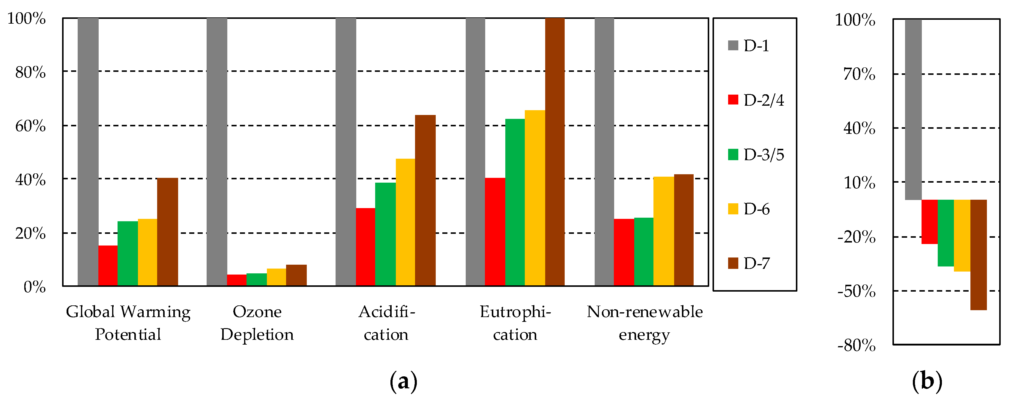
The Cradle-to-Gate environmental impacts for each category are illustrated in Figure 8a and quantities are given in an equivalent unit. For example, kilograms of carbon dioxide are used as an equivalent unit to measure global warming potential. Figure 9 shows the difference in impacts for each building design using the existing building (D-1) as a baseline with 100% for all categories.
When analyzing the environmental impact of timber, including the effects that occur beyond the building life have a significant impact on the global warming potential. This is because wood sequesters carbon from the atmosphere [45] and effect which is taken into consideration at the end of its useful life in the building. Figure 8b shows that the global warming potential for the mass-timber design is negative, that is, using mass-timber reverses the effects of global warming due to carbon sequestration. For the concrete design, however, including the impacts beyond the building life increases the global warming potential. The Cradle-to-Grave impact assessment causes no significant change in the other four impact categories.
Analyzing the results from Athena Impact Estimator for Buildings it is evident that the use of mass-timber cores in place of concrete has significant environmental benefits for the UBC TWB. Regarding the Cradle-to-Gate impacts, the concrete core building has the highest impact in all but one category when compared to the mass-timber layouts. Design D-3 with LVL walls has a 3% higher eutrophication potential when compared to D-1 with concrete, however, it is significantly lower in all other impact categories. For the mass-timber layouts, the more material used, the higher the environmental impact of the building. Conversely, when looking at the effects beyond the building life (Cradle-to-Grave assessment) the larger volume of timber corresponds with a decrease in global warming potential due to the carbon sequestration of the wood.
6. Conclusions
The objective of this work was to investigate the feasibility of using mass-timber cores (designed in CLT and LVL) and an option with additional ‘C-shaped’ mass-timber walls to replace the concrete cores of the UBC Tall Wood Building. Based on the Finite Element, Modal, Linear Dynamic Response Spectrum, and Dynamic Wind as well as Life Cycle Analyses, it can be concluded that:
- The side position of the cores induced a notable torsional component on the lateral response of the building, particularly evident in the case of mass-timber cores. The findings suggest the inclusion of additional shear walls to help reduce plan torsional sensitivity;
- Only design options D-4 and D-7 with LVL walls met all NBCC lateral design requirements; however, only the solution with additional ‘C-shaped’ walls appears feasible since it is unrealistic for timber panels to use completely rigid joints to build monolithic cores as assumed for D-4;
- The LVL design D-5, which had the stiffness of cores reduced by 50% to account for the joints between panels as per the authors simplified preliminary design assumption, exhibited seismic and wind performance close to code limits of 2.5% and 0.2%, respectively;
- Even for a model assuming monolithic cores, it seems unreasonable to pursue the solution with CLT for the TWB with the original layout. This recommendation is also conditioned by the commercially available CLT panel thickness, currently limited to 315 mm in Canada;
- The LCA demonstrated that the use of a mass-timber LLRS for the UBC TWB would have significant environmental benefits in regard to the impact categories recognized by LEED v4;
- Future research should investigate (i) the stiffness and capacity of horizontal and vertical connections for CLT and LVL cores; (ii) the impact of adding un-bonded post-tensioned cables; and (iii) the behavior of balloon-framed CLT/LVL systems to provide Ro and Rd factors;
- With such further research, code provisions and design rules could be developed to increase the use of mass-timber as lateral load-resisting systems.
Author Contributions
T.C. developed the numerical models and conducted the lateral load and life cycle analyses. T.T. provided the background information on the Tall Wood Building and supervised the project. C.L. and A.I. supported the project throughout. The paper was jointly written by all co-authors.
Funding
This research was supported by the British Columbia Innovation Council through funding to the BC Leadership Chair in Tall Wood and Hybrid Structures Engineering.
Conflicts of Interest
The authors declare no conflict of interest.
References
- Foliente, G. History of timber construction. In Wood Structures: A Global Forum on the Treatment, Conservation and Repair of Cultural Heritage; Kelley, S., Loferski, J., Salenikovich, A., Stern, E., Eds.; ASTM International: West Conshohocken, PA, USA, 2000; pp. 3–22. [Google Scholar]
- Buchanan, A.H.; John, S.; Love, S. LCA and carbon footprint of multi-story timber buildings compared with steel and concrete buildings. N. Z. J. For. 2013, 57, 9–18. [Google Scholar]
- De Wolf, C.; Pomponi, F.; Moncaster, A. Measuring embodied carbon dioxide equivalent of buildings: A review and critique of current industry practice. Energy Build. 2017, 140, 68–80. [Google Scholar] [CrossRef]
- Karacabeyli, E.; Lum, C. Technical Guide for the Design and Construction of Tall Wood Buildings in Canada; Special Publication SP-55E; FPInnovations: Vancouver, BC, Canada, 2014. [Google Scholar]
- Smith, I.; Frangi, A. Use of Timber in Tall Multi-Story Buildings; Structural Engineering Document 13 (SED13); International Association for Bridge and Structural Engineering (IABSE): Zurich, Switzerland, 2014; ISBN 978-3-85748-132-1. [Google Scholar]
- Green, M.; Karsh, J.E. Tall Wood-The Case for Tall Wood Buildings, 2nd ed.; Wood Enterprise Coalition: Vancouver, BC, Canada, 2018. [Google Scholar]
- National Research Council of Canada (NRCC). British Columbia Building Code; NRCC: Victoria, BC, Canada, 2012; ISBN 978-0-7726-6593-5. [Google Scholar]
- Jeske, J.; Esposito, D. Reference Guide: Mid-Rise Wood Construction in the Ontario Building Code Report; Report No. 2150027.00; Hershfield, M., Ed.; Ontario Wood WORKS: North Bay, ON, Canada, 2015. [Google Scholar]
- Brandner, R.; Flatscher, G.; Ringhofer, A.; Schickhofer, G.; Thiel, A. Cross laminated timber (CLT): Overview and development. Eur. J. Wood Wood Prod. 2016, 74, 331–351. [Google Scholar] [CrossRef]
- Ceccotti, A.; Sandhaas, C.; Okabe, M.; Yasumura, M.; Minowa, C.; Kawai, N. SOFIE project—3D shaking table test on a seven-story full-scale cross-laminated timber building. Earthq. Eng. Struct. Dyn. 2013, 42, 2003–2021. [Google Scholar] [CrossRef]
- Gavric, I.; Fragiacomo, M.; Ceccotti, A. Cyclic behavior of CLT wall systems: Experimental tests and analytical prediction models. J. Struct. Eng. 2015, 141, 04015034. [Google Scholar] [CrossRef]
- Pei, S.; van de Lindt, J.W.; Popovski, M.; Berman, J.W.; Dolan, J.D.; Ricles, J.M.; Sause, R.; Blomgren, H.; Rammer, D.R. Cross laminated timber for seismic regions: Progress and challenges for research and implementation. J. Struct. Eng. 2016, 142, E2514001. [Google Scholar] [CrossRef]
- Shahnewaz, M.; Tannert, T.; Alam, M.S.; Popovski, M. In-plane stiffness of cross-laminated timber panels with openings. Struct. Eng. Int. 2017, 27, 217–223. [Google Scholar] [CrossRef]
- Dietsch, P.; Brandner, R. Self-tapping screws and threaded rods as reinforcement for structural timber elements—A state-of-the-art report. Constr. Build. Mater. 2015, 97, 78–89. [Google Scholar] [CrossRef]
- Hossain, A.; Danzig, I.; Tannert, T. Cross-laminated timber shear connection with innovative self-tapping screw assemblies. J. Struct. Eng. 2016, 142, 04016099. [Google Scholar] [CrossRef]
- Hossain, A.; Popovski, M.; Tannert, T. Cross-laminated timber connections assembled with a combination of screws in withdrawal and screws in shear. Eng. Struct. 2018, 168, 1–11. [Google Scholar] [CrossRef]
- Newcombe, M.P.; Pampanin, S.; Buchanan, A.; Palermo, A. Section analysis and cyclic behavior of post-tensioned jointed ductile connections for multi-story timber buildings. J. Earthq. Eng. 2008, 12, 83–110. [Google Scholar] [CrossRef]
- Iqbal, A.; Pampanin, S.; Buchanan, A.H. Seismic performance of full-scale post-tensioned timber beam-column connections. J. Earthq. Eng. 2016, 20, 383–405. [Google Scholar] [CrossRef]
- Ganey, R.; Berman, J.; Akbas, T.; Loftus, S.; Dolan, J.D.; Sause, R.; Ricles, J.; Pei, S.; van de Lindt, J.; Blomgren, H.E. Experimental investigation of self-centering cross-laminated timber walls. J. Struct. Eng. 2017, 143, 04017135. [Google Scholar] [CrossRef]
- Tesfamariam, S.; Stiemer, S.F.; Dickof, C.; Bezabeh, M.A. Seismic vulnerability assessment of hybrid steel-timber structure: Steel moment resisting frames with CLT infill. J. Earthq. Eng. 2014, 18, 929–944. [Google Scholar] [CrossRef]
- Zhang, X.; Fairhurst, M.; Tannert, T. Ductility estimation for a novel timber–steel hybrid system. J. Struct. Eng. 2016, 142, E4015001. [Google Scholar] [CrossRef]
- Zhang, X.; Riasat, A.; Bhat, P.; Popovski, M.; Tannert, T. Seismic performance of embedded steel beam connection in cross-laminated timber panels for tall-wood hybrid system. Can. J. Civ. Eng. 2017, 44, 611–618. [Google Scholar] [CrossRef] [Green Version]
- Skidmore, Owings & Merrill (SOM), LLP. Timber Tower Research Project; Final Report; SOM: Chicago, IL, USA, 2013; Available online: http://www.som.com (accessed on 20 June 2018).
- Dias, A.; Skinner, J.; Crews, K.; Tannert, T. Timber-concrete-composites increasing the use of timber in construction. Eur. J. Wood Wood Prod. 2016, 74, 443–451. [Google Scholar] [CrossRef]
- Skidmore, Owings & Merrill (SOM), LLP. AISC Steel & Timber Research for High-Rise Residential Buildings; Final Report; SOM: Chicago, IL, USA, 2017; Available online: http://www.som.com (accessed on 20 June 2018).
- Loss, C.; Frangi, A. Experimental investigation on in-plane stiffness and strength of innovative steel-timber hybrid floor diaphragms. J. Eng. Struct. 2017, 138, 229–244. [Google Scholar] [CrossRef]
- Loss, C.; Rossi, S.; Tannert, T. In-plane stiffness of hybrid steel-cross-laminated timber floor diaphragms. J. Struct. Eng. 2018, 144, 04018128. [Google Scholar] [CrossRef]
- Poirier, E.; Moudgil, M.; Fallahi, A.; Staub-French, S.; Tannert, T. Design and construction of a 53 meter tall timber building at the university of British Columbia. In Proceedings of the World Conference on Timber Engineering (WCTE2016), Vienna, Austria, 22–25 August 2016. [Google Scholar]
- Malo, K.A.; Abrahamsen, R.B.; Bjertnæs, M.A. Some structural design issues of the 14-story timber framed building “Treet” in Norway. Eur. J. Wood Wood Prod. 2016, 74, 407–424. [Google Scholar] [CrossRef]
- Tannert, T.; Moudgil, M. Structural design, approval and monitoring of UBC Tall Wood Building. In Proceedings of the ASCE Structures Congress, Denver, CO, USA, 6–8 April 2017. [Google Scholar]
- Bergen, N. Case study of UBC Brock Commons—Construction details and methods. In Proceedings of the World Conference on Timber Engineering (WCTE2016), Vienna, Austria, 22–25 August 2016. [Google Scholar]
- Fast, P.; Gafner, B.; Jackson, R.; Li, J. Case study: An 18 story tall mass timber hybrid student residence at the University of British Columbia, Vancouver. In Proceedings of the World Conference on Timber Engineering (WCTE2016), Vienna, Austria, 22–25 August 2016. [Google Scholar]
- Flatscher, G.; Schickhofer, G. Displacement-based determination of laterally loaded cross laminated timber (CLT) wall systems. In Proceedings of the International Network on Timber Engineering Research (INTER2016), Graz, Austria, 16–19 August 2016. [Google Scholar]
- Polastri, A.; Loss, C.; Pozza, L.; Smith, I. CLT buildings laterally braced with core and perimeter walls. In Proceedings of the World Conference on Timber Engineering (WCTE2016), Vienna, Austria, 22–25 August 2016. [Google Scholar]
- Izzi, M.; Polastri, A.; Fragiacomo, M. Investigating the hysteretic behavior of Cross-Laminated Timber wall systems due to connections. J. Struct. Eng. 2018, 144. [Google Scholar] [CrossRef]
- National Research Council of Canada (NRCC). National Building Code of Canada 2015; NRCC: Ottawa, ON, Canada, 2015; Volume 1, p. 708; Volume 2, p. 696. [Google Scholar]
- Canadian Standards Association (CSA). CSA-O86-2016 Engineering Design in Wood; 2016 update to the 2014 standard edition; CSA Group: Mississauga, ON, Canada, 2016. [Google Scholar]
- Canadian Standards Association (CSA). A23.3-14 Design of Concrete Structures; CSA Group: Ottawa, ON, Canada, 2014. [Google Scholar]
- Crosslam® CLT-Technical Design Guide. Available online: http://www.structurlam.com/ (accessed on 20 June 2018).
- Canadian Construction and Materials Centre (CCMC). Evaluation Report CCMC 11518-R: LP-Solid Start LVL. 2015. Available online: https://lpcorp.com (accessed on 20 June 2018).
- Natural Resources Canada (NRC). Determine 2015 National Building Code of Canada Seismic Hazard Values; NRC: Ottawa, ON, Canada; Available online: http://www.earthquakescanada.nrcan.gc.ca/ (accessed on 30 October 2017).
- Dlubal. Structural Engineering Software for Analysis and Design; RFEM Version 5.11; Dlubal Software, Inc.: Philadelphia, PA, USA, 2017. [Google Scholar]
- Athena Institute. Athena Impact Estimator for Buildings Version 5.2.0119; Athena Sustainable Materials Institute: Ottawa, ON, Canada, 2017. [Google Scholar]
- LEED Canada for New Construction and Major Renovations 2009: Rating System. Available online: https://www.cagbc.org (accessed on 20 June 2018).
- Skog, K.E.; Nicholson, G.A. Carbon Cycling through wood products: The role of wood and paper products in carbon sequestration. For. Prod. J. 1998, 48, 75–83. [Google Scholar]
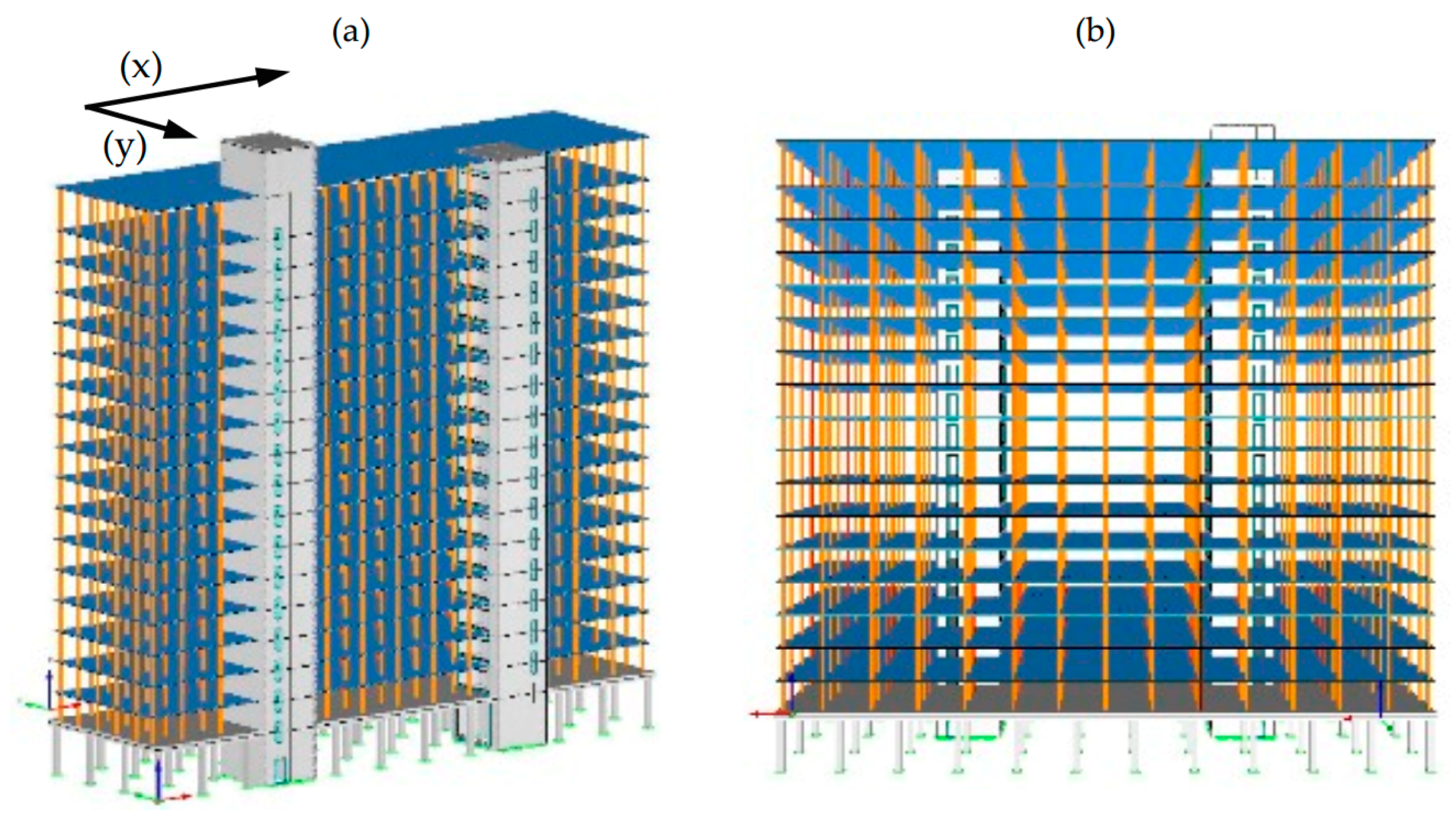
Figure 1.
TWB: (a) building, (b) typical floor plan (partial section) and (c) longitudinal section (courtesy Acton Ostry Architects Inc., Vancouver, BC, Canada).
Figure 1.
TWB: (a) building, (b) typical floor plan (partial section) and (c) longitudinal section (courtesy Acton Ostry Architects Inc., Vancouver, BC, Canada).

Figure 2.
Joints: (a) Column-to-slab connections, (b) ledgers for floors, (c) steel drag strap connections for floors and (d) vertical connections for columns.
Figure 2.
Joints: (a) Column-to-slab connections, (b) ledgers for floors, (c) steel drag strap connections for floors and (d) vertical connections for columns.

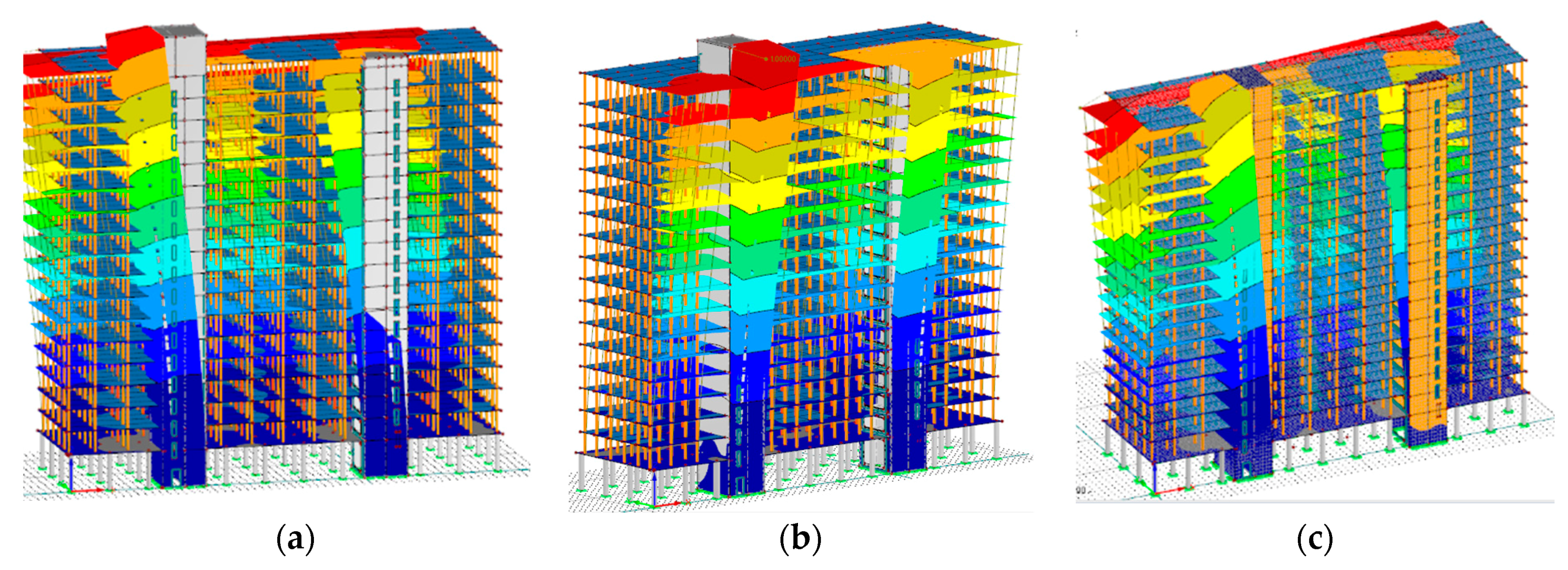
Figure 3.
LLRS layouts for numerical models: (a) cores as in original building for designs D-2–D-5; (b) cores and additional C-shaped walls for design D-6–D-7.
Figure 3.
LLRS layouts for numerical models: (a) cores as in original building for designs D-2–D-5; (b) cores and additional C-shaped walls for design D-6–D-7.

Figure 4.
UHS for Vancouver based on TWB’s location.

Figure 5.
Numerical Model of the UBC TWB: (a) isometric view and (b) front view.

Figure 6.
Mode shapes of TWB (a) 1st: translation in X-direction; (b) 2nd: translation in X-direction; (c) 3rd torsion.
Figure 6.
Mode shapes of TWB (a) 1st: translation in X-direction; (b) 2nd: translation in X-direction; (c) 3rd torsion.

Figure 7.
Inter-story drift profile for the X-direction (a) and Y-direction (b) under seismic loads.
Figure 7.
Inter-story drift profile for the X-direction (a) and Y-direction (b) under seismic loads.

Figure 8.
Inter-story drift profile for the X-direction (a) and Y-direction (b) under wind loads.

Figure 9.
LCA: (a) ‘Cradle-to-Gate’ impact categories and (b) total global warming potential.


| Property | Concrete | CLT | LVL |
|---|---|---|---|
| E1 | 26,540 | 12,400 (0°-layers) 9500 (90°-layers) | 13,800 |
| G23 | 11,058 | 78 (0°-layers); 59 (90°-layers) | 55 |
| G12, G13 | 775 (0°-layers); 594 (90°-layers) | 550 |
Table 2.
Results from modal analyses.
| Design | T1 (s) | T2 (s) | T3 (s) | ∑mx (%) | ∑my (%) |
|---|---|---|---|---|---|
| D-1* | 2.0 | 1.7 | 1.4 | n/a | n/a |
| D-1 | 2.0 | 1.5 | 1.3 | 77 | 61 |
| D-2 | 4.3 | 3.0 | 2.8 | 87 | 84 |
| D-3 | 6.1 | 4.3 | 4.3 | 89 | 89 |
| D-4 | 3.0 | 2.1 | 2.0 | 87 | 86 |
| D-5 | 4.3 | 3.1 | 3.0 | 89 | 90 |
| D-6 | 3.9 | 3.5 | 3.1 | 83 | 83 |
| D-7 | 2.8 | 2.6 | 2.3 | 84 | 84 |
Table 3.
Results from response spectrum analysis.
| Design | Vb,X (kN) | Vb,Y (kN) | θmax,X (%) | θmax,Y (%) |
|---|---|---|---|---|
| D-1 | 34,285 (6122) | 36,847 (7184) | 1.1 | 1.3 |
| D-2 | 20,882 (19,322) | 30,209 (23,238) | 1.9 | 2.7 |
| D-3 | 22,662 (19,322) | 25,118 (19,322) | 3.5 | 3.3 |
| D-4 | 28,617 (22,013) | 34,624 (26,634) | 1.5 | 1.8 |
| D-5 | 21,405 (19,931) | 30,870 (23,746) | 1.8 | 2.6 |
| D-6 | 25,056 (19,743) | 27,752 (21,348) | 1.6 | 3.0 |
| D-7 | 30,682 (23,602) | 33,829 (26,022) | 1.3 | 2.5 |
Table 4.
Results from the dynamic wind analysis.
| Design | Vb,X (kN) | Vb,Y (kN) | θmax,X (%) | θmax,Y (%) |
|---|---|---|---|---|
| D-1 | 615 | 2319 | 0.02 | 0.04 |
| D-2 | 804 | 2856 | 0.13 | 0.23 |
| D-3 | 925 | 3286 | 0.27 | 0.52 |
| D-4 | 699 | 2538 | 0.06 | 0.09 |
| D-5 | 808 | 2867 | 0.12 | 0.22 |
| D-6 | 747 | 2633 | 0.07 | 0.32 |
| D-7 | 668 | 2412 | 0.04 | 0.14 |
Table 5.
Material quantities considered for LCA.
| Design | Cores | Caps + Stairs | ||
|---|---|---|---|---|
| Material | Volume (m3) | Material | Volume (m3) | |
| D-1 | Concrete | 1314 | Concrete | 147 |
| D-2 | CLT | 928 | CLT | 116 |
| D-4 | LVL | 1311 | CLT | 116 |
| D-6 | CLT | 1583 | CLT | 116 |
| D-7 | LVL | 2236 | CLT | 116 |
© 2018 by the authors. Licensee MDPI, Basel, Switzerland. This article is an open access article distributed under the terms and conditions of the Creative Commons Attribution (CC BY) license (http://creativecommons.org/licenses/by/4.0/).
Share and Cite
MDPI and ACS Style
Connolly, T.; Loss, C.; Iqbal, A.; Tannert, T. Feasibility Study of Mass-Timber Cores for the UBC Tall Wood Building. Buildings 2018, 8, 98. https://doi.org/10.3390/buildings8080098
AMA Style
Connolly T, Loss C, Iqbal A, Tannert T. Feasibility Study of Mass-Timber Cores for the UBC Tall Wood Building. Buildings. 2018; 8(8):98. https://doi.org/10.3390/buildings8080098
Chicago/Turabian StyleConnolly, Thomas, Cristiano Loss, Asif Iqbal, and Thomas Tannert. 2018. "Feasibility Study of Mass-Timber Cores for the UBC Tall Wood Building" Buildings 8, no. 8: 98. https://doi.org/10.3390/buildings8080098
Note that from the first issue of 2016, this journal uses article numbers instead of page numbers. See further details here.