Optimal Passive Dynamics for Physical Interaction: Catching a Mass

Abstract
:1. Introduction

2. Background
3. Problem Domain

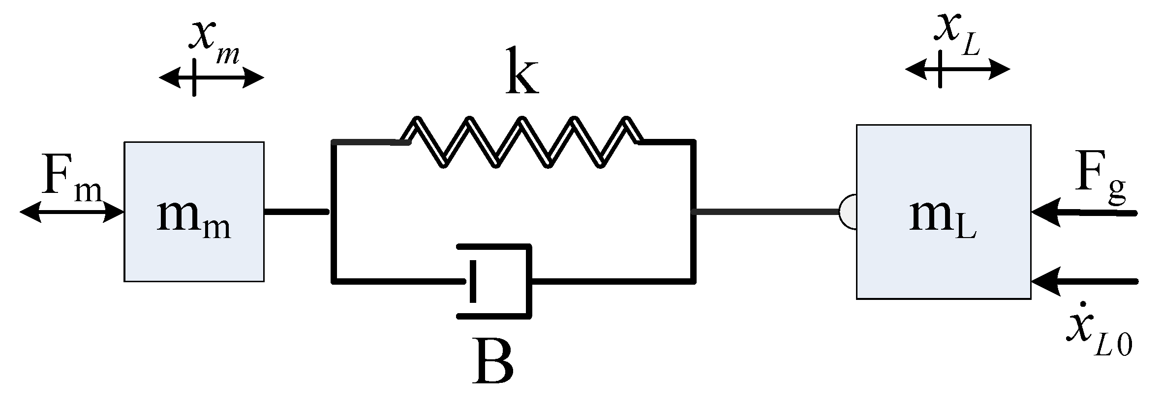
| Symbol | Description | Unit |
|---|---|---|
| Load position | m | |
| Motor position | m | |
| Rigid body motion of two masses | m | |
| Relative motion of two masses | m | |
| k | Spring constant | |
| B | Damping constant | |
| g | Acceleration of gravity | |
| Motor/transmission mass | ||
| Load mass | ||
| Motor force | N | |
| Motor force limit | N | |
| Force due to gravity | N | |
| Force caused by the dynamic elements | N | |
| Load initial velocity |
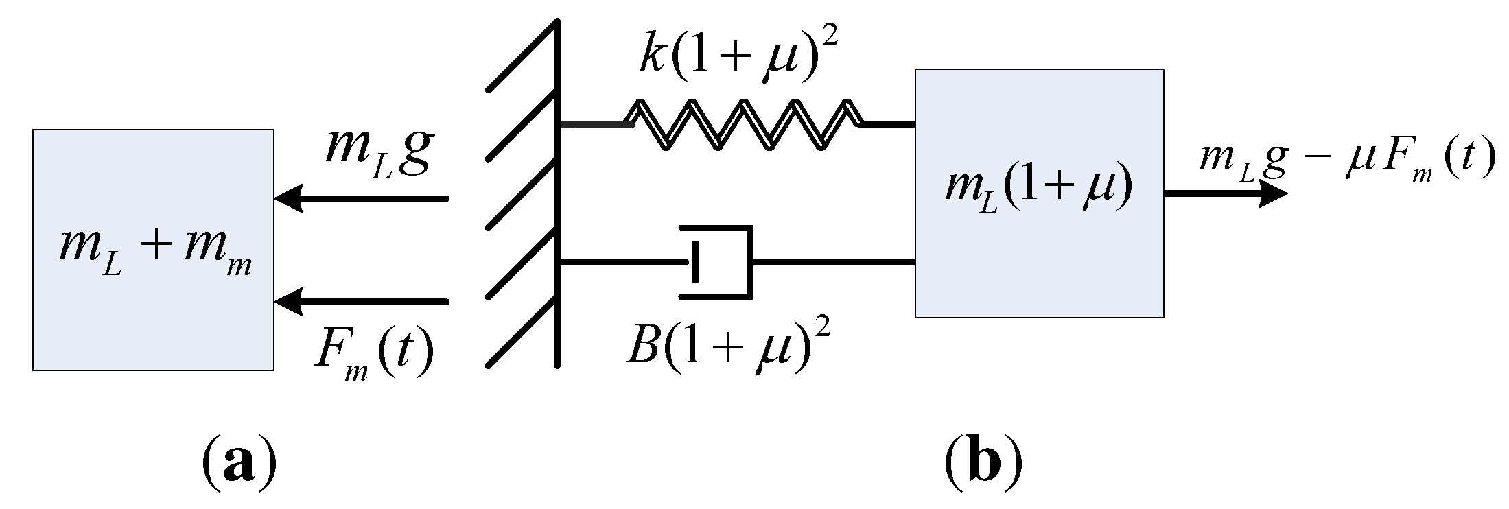
4. System Model
5. Controller


6. Undamped Actuator: Analytical Derivation

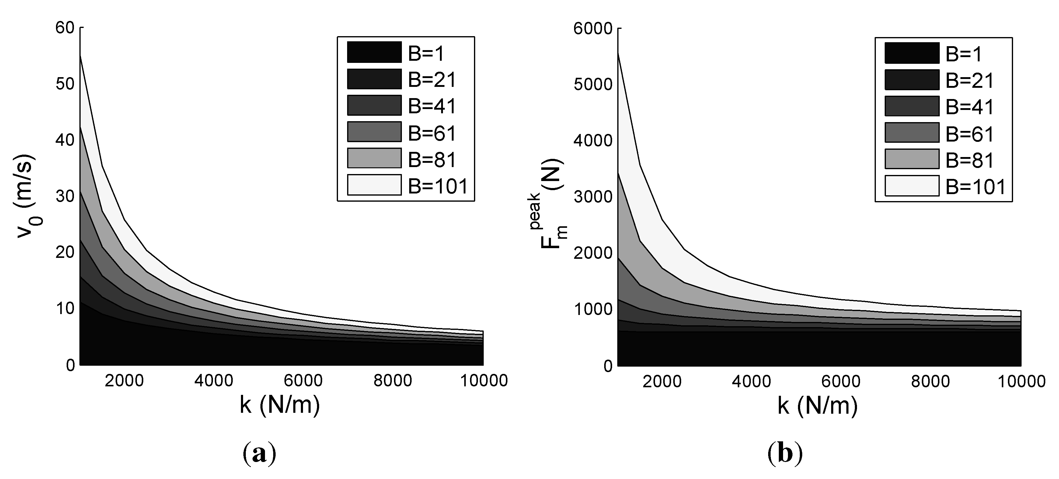
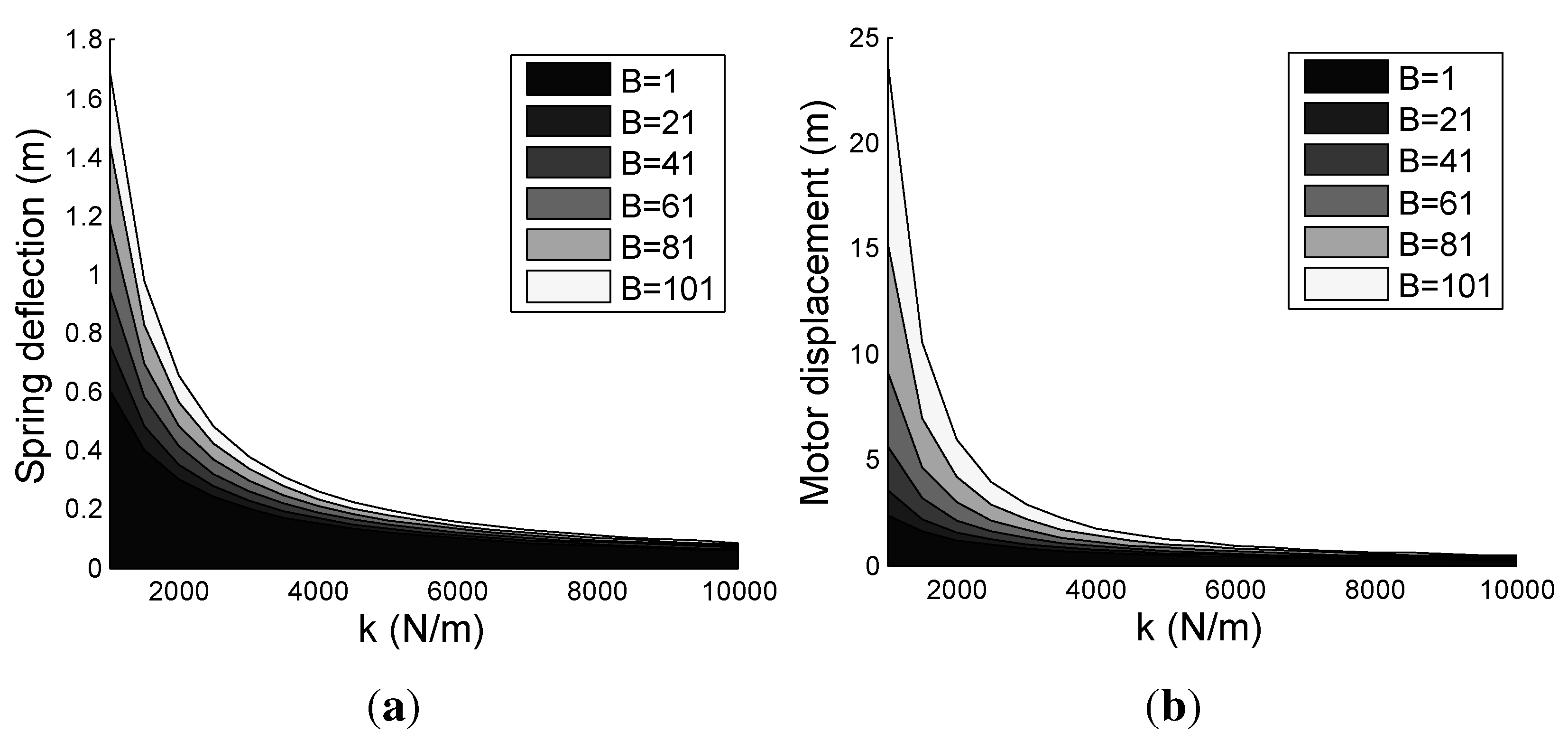
7. Results

8. Conclusions and Future Work
References
- Barteit, D.; Frank, H.; Kupzog, F. Accurate Prediction of Interception Positions for Catching Thrown Objects in Production Systems. In Proceedings of the 6th IEEE Internacional Conference on Industrial Informatics, Daejeon, Korea, 13–16 July 2008; pp. 893–898.
- Kemper, K.; Koepl, D.; Hurst, J. Optimal Passive Dynamics for Torque/Force Control. In Proceedings of IEEE International Conference on the Robotics and Automation (ICRA), Anchorage, AK, USA, 3–8 May 2010; pp. 2149–2154.
- Cavagna, G.A. Elastic bounce of the body. J. Appl. Physiol. 1970, 29, 279–282. [Google Scholar] [PubMed]
- Full, R.J.; Farley, C.T. Musculoskeletal Dynamics in Rhythmic Systems-A Comparative Approach to Legged Locomotion. In Biomechanics and Neural Control of Posture and Movement; Winters, J.M., Crago, P.E., Eds.; Springer-Verlag: New York, NY, USA, 2000. [Google Scholar]
- McMahon, T.A. The role of compliance in mammalian running gaits. J. Exp. Biol. 1985, 115, 263–282. [Google Scholar] [PubMed]
- Hurst, J.W.; Rizzi, A.A. Series compliance for an efficient running gait: Lessons learned from the ECD leg. IEEE Robot. Autom. Mag. 2008, 15, 42–51. [Google Scholar] [CrossRef]
- Raibert, M. Legged Robots that Balance; MIT Press: Cambridge, MA, USA, 1986. [Google Scholar]
- Hurst, J.W. The electric cable differential leg: A novel design approach for walking and running. Int. J. Humanoid Robot. 2011, 8, 301–321. [Google Scholar] [CrossRef]
- Grimes, J.; Hurst, J. The Design of ATRIAS 1.0 a Unique Monopod, Hopping Robot. In Proceedings of the International Conference on Climbing and Walking Robots (CLAWAR), Baltimore, MD, USA, 23–26 July 2012.
- An, C.; Hollerbach, J. Dynamic Stability Issues in Force Control of Manipulators. In Proceedings of IEEE International Conference on the Robotics and Automation, Raleigh, NC, 30 March–3 April 1987; Volume 4, pp. 890–896.
- Bauml, B.; Wimbock, T.; Hirzinger, G. Kinematically Optimal Catching a Flying Ball with a Hand-Arm-System. In Proceedings of IEEE/RSJ International Conference on Intelligent Robots and Systems (IROS), Taipei, Taiwan, 18–22 October 2010; pp. 2592–2599.
- Haddadin, S.; Albu-Schaffer, A.; de Luca, A.; Hirzinger, G. Collision Detection and Reaction: A Contribution to Safe Physical Human-Robot Interaction. In Proceedings of IEEE/RSJ International Conference on Intelligent Robots and Systems (IROS), Nice, France, 22–26 September 2008; pp. 3356–3363.
- Schutter, J.D. A Study of Active Compliant Motion Control Methods for Rigid Manipulators Based on a Generic Control Scheme. In Proceedings of the IEEE International Conference on Robotics and Automation, Raleigh, NC, 30 March–3 April 1987; pp. 1060–1065.
- Whitney, D.E. Force feedback control of manipulator fine motions. J. Dyn. Syst. Meas. Control 1977, 99, 91–97. [Google Scholar] [CrossRef]
- Haddadin, S.; Mansfeld, N.; Albu-Schaffer, A. Rigid vs. Elastic Actuation: Requirements and Performance. In Proceedings of IEEE/RSJ International Conference on Intelligent Robots and Systems (IROS), Vilamoura-Algarve, Portugal, 7–11 October 2012; pp. 5097–5104.
- Braun, D.; Howard, M.; Vijayakumar, S. Optimal Variable Stiffness Control: Formulation and Application To Explosive Movement Tasks. Auton. Robot. 2012, 33, 237–253. [Google Scholar] [CrossRef]
- Garabini, M.; Passaglia, A.; Belo, F.; Salaris, P.; Bicchi, A. Optimality Principles in Stiffness Control: The VSA Kick. In Proceedings of IEEE International Conference on Robotics and Automation (ICRA), Saint Paul, MI, USA, 14–18 May 2012; pp. 3341–3346.
- Pratt, G.A.; Williamson, M.M. Series Elastic Actuators. In Proceedings of the IEEE International Conference on Intelligent Robots and Systems, Pittsburgh, PA, USA, 5–9 August 1995; Volume 1, pp. 399–406.
- Robinson, D.W. Design and Analysis of Series Elasticity in Closed-Loop Actuator Force Control. Ph.D. Thesis, Massachusetts Institute of Technology, Cambridge, MA, USA, June 2000. [Google Scholar]
- Sensinger, J.; Weir, R. User-modulated impedance control of a prosthetic elbow in unconstrained, perturbed motion. IEEE Trans. Biomed. Eng. 2008, 55, 1043–1055. [Google Scholar] [CrossRef] [PubMed]
- Wyeth, G. Demonstrating the Safety and Performance of a Velocity Sourced Series Elastic Actuator. In Proceedings of IEEE International Conference on Robotics and Automation (ICRA), Pasadena, CA, USA, 19–23 May 2008; pp. 3642–3647.
- Edsinger-Gonzales, A.; Weber, J. Domo: A Force Sensing Humanoid Robot for Manipulation Research. In Proceedings of 4th IEEE/RAS International Conference on the Humanoid Robots, Santa Monica, CA, USA, 10–12 November 2004; Volume 1, pp. 273–291.
- Sensinger, J.; Weir, R. Improved torque fidelity in harmonic drive sensors through the union of two existing strategies. IEEE/ASME Trans. Mechatron. 2006, 11, 457–461. [Google Scholar] [CrossRef]
- Tsagarakis, N.; Laffranchi, M.; Vanderborght, B.; Caldwell, D. A Compact Soft Actuator Unit for Small Scale Human Friendly Robots. In Proceedings of IEEE International Conference on Robotics and Automation (ICRA), Kobe, Japan, 12–17 May 2009; pp. 4356–4362.
- Buerger, S.; Hogan, N. Complementary stability and loop shaping for improved human ndash: Robot interaction. IEEE Trans. Robot. 2007, 23, 232–244. [Google Scholar] [CrossRef]
- Hurst, J.W.; Hobbelen, D.; Rizzi, A.A. Series Elastic Actuation: Potential and Pitfalls. In Proceedings of the IROS Workshop, Edmonton, Canada, 2–6 August 2005.
© 2013 by the authors; licensee MDPI, Basel, Switzerland. This article is an open access article distributed under the terms and conditions of the Creative Commons Attribution license (http://creativecommons.org/licenses/by/3.0/).
Share and Cite
Kemper, K.; Vejdani, H.R.; Piercy, B.; Hurst, J. Optimal Passive Dynamics for Physical Interaction: Catching a Mass. Actuators 2013, 2, 45-58. https://doi.org/10.3390/act2020045
Kemper K, Vejdani HR, Piercy B, Hurst J. Optimal Passive Dynamics for Physical Interaction: Catching a Mass. Actuators. 2013; 2(2):45-58. https://doi.org/10.3390/act2020045
Chicago/Turabian StyleKemper, Kevin, Hamid Reza Vejdani, Brent Piercy, and Jonathan Hurst. 2013. "Optimal Passive Dynamics for Physical Interaction: Catching a Mass" Actuators 2, no. 2: 45-58. https://doi.org/10.3390/act2020045