A Mechanical Musculo-Skeletal System for a Human-Shaped Robot Arm

Department of Mechanical Engineering, Tokai University, 4-1-1 Kitakaname, Hiratsuka, Kanagawa 259-1292, Japan
Actuators 2014, 3(2), 124-141; https://doi.org/10.3390/act3020124
Submission received: 20 December 2013
/
Revised: 12 May 2014
/
Accepted: 13 May 2014
/
Published: 17 June 2014
(This article belongs to the Special Issue Soft Actuators)
Abstract
:This paper presents a mechanical system with a similar configuration to a human musculo-skeletal system for use in anthropomorphic robots or as artificial limbs for disabled persons. First, a mechanical module called ANLES (Actuator with Non-Linear Elasticity System) is introduced. There are two types of ANLES: the linear-type ANLES and rotary-type ANLES. They can be used as a voluntary muscle in a wide-range of musculo-skeletal structures in which at least double actuators work in an antagonistic setup via some elastic elements. Next, an application of the two types of ANLES to a two-degree-of-freedom (DOF) manipulator that has a similar configuration to the human elbow joint is shown. The experimental results of the joint stiffness and joint angle control elucidate that the developed mechanism effectively regulates joint stiffness in the same way as a musculo-skeletal system.

1. Introduction
Dexterous behaviors of human articulations are mostly due to the adjustability of their stiffness in response to external interferences. The musculo-skeletal system of human articulations is able to regulate stiffness prior to the actual performance of a task without using exteroceptive force or tactile feedback. The key mechanism for regulating stiffness is an antagonistic structure of the musculo-skeletal system: one agonist and its antagonist muscles counteractively drive one articulation. Simultaneous stretching/relaxing of both muscles increase/decrease the stiffness of articulations.
A non-linear elasticity of individual muscles is prerequisite for the agonist-antagonist alignment to regulate stiffness. Some amount of the rotation of an articulation requires a respectively small torque under an equilibrium state of low stretching of both muscles. On the other hand, an equilibrium state under high stretching requires a respectively large torque to provide the same rotational angle. Therefore, stiffness is regulated according to the magnitude of the stretching of both muscles. It is obvious that linear elasticity does not provide such a stiffness change because a derivative of the linear elasticity with respect to joint rotation, which is only stiffness, is constant.
A vast amount of physiological studies have elucidated that skeletal muscles have such a non-linear elasticity as that mentioned above [1,2,3,4].
Some studies for investigating the stiffness of human arms elucidate that the stiffness ellipsoid of the arm’s endpoint is adjustable in its volume by stretching muscles [5], but its shape is roughly determined by the arm’s posture [6].
Some studies in the field of robotics deal with the antagonistic control of joints [7,8,9,10,11,12] and have noted the importance of the non-linear characteristics of elastic elements to control the stiffness of joints [9,10,11], but there have been few papers that proposed a control method of stiffness from the practical point of view, although some theoretical approaches for stiffness control have provided valuable insight [11,13,14].
This study assumes artificial joints that are controlled by at least two actuator units having a similar elastic characteristic to human voluntary muscles, called antagonistically driven joints (ADJ).
There have been some approaches composing ADJ using linear actuators that work like muscles. The most successful approach developed so far are approaches using the McKibben-type pneumatic actuator [15,16]. Although pneumatic rubber actuators inherently have non-linear elasticity, there are some drawbacks, such as the difficulty of designing non-linear elasticity, heat sensitivity, and the large volume of the apparatus necessary for supplying compressed air. The “pleated pneumatic artificial muscle” (PPAM) [17] is an approach to overcome some problems that pneumatic actuators have had, such as a short lifespan and large hysteresis in force/contract relations.
There have been some other recent approaches to develop a non-linear elastic module used to control the stiffness of ADJ [18,19,20,21] that have presented ingenious mechanical devices to design a non-linear elasticity.
Recent ardency for developing ADJ, introduced above, suggests the importance of ADJ and the potential of practical application in the near future. Because a forthcoming “Personal Care Robot” will need to be inherently safe when it interacts with external objects, especially with the human body [22], it requires mechanical resiliency and adaptability rather than a feedback control system that artificially provides them with sensor information. Our study is one approach in the research stream mentioned above to compose ADJ.
Recently, various types of mechanisms classified as variable stiffness actuators (VSAs) have been proposed [23,24,25,26,27,28,29], of which a pioneering work, known as the MIA (mechanical impedance adjuster), has been developed by Morita and Sugano [30]. The VSA approach aims to endow robots with an intrinsically safe property for use in a human-robot interactive environment. The VSA is an actuator unit that has an adjustable elastic element between the rotary joint and rotary actuator, or has a mechanism to regulate the elasticity of the elastic element. Therefore, the VSA does not aim to compose an ADJ Also, it will be explained that the VSA developed so far is rather difficult to incorporate into a joint that has multiple rotary axes similar to a wrist joint or a hip joint because of its structural nature as a rotary actuator, although there has been a design proposition to implement the VSA into a three-degree-of-freedom (DOF) joint [31].
This paper proposes an alternative mechanism of an artificial muscle to comprise the ADJ. The mechanism has a similar concept to [20,21] in the sense of yielding a non-linear elasticity by converting the force generated by a normal linear spring into a transmission process [32,33,34]. This study aims to develop an intrinsically safe device equal to the VSA approach. In our past study, we developed a muscle-like actuator: the Actuator with a Non-Linear Elasticity System (ANLES). The basic idea of the ANLES was proposed in [32] with experimental results using a simple one-DOF joint controlled by a pair of prototypical ANLESes. A linear actuator based on the ANLES, called l-ANLES, was introduced in [33] to control a joint with multiple DOFs like a wrist joint with multiplel-ANLESes. Subsequently, a rotary-type ANLES, called r-ANLES, was introduced in [34] to control the pronation/supination of a wrist joint. However, the application presented in [33,34] was very limited in the range of joint rotation and the size of the joint. Therefore, this paper presents another application of ANLES into an upper-arm that requires a wide range of joint rotation and countermeasures for the weight itself.
In the following section, two types of ANLESes are introduced: the linear type ANLES (l-ANLES) and the rotary type ANLES (r-ANLES). Both ANLESes are used as voluntary muscles to control a joint in an antagonistic setup as a musculo-skeletal system. The third section shows an application of both types of ANLES into a two-DOF manipulator that has a configuration similar to the human elbow joint. The flexion/extension of the elbow joint is controlled by a pair of l-ANLES, while the lateral/medial rotation of the upper-arm is controlled by a pair of r-ANLES. This paper also shows a weight compensation mechanism for cancelling the weight of the forearm and the end-effector. The last section is devoted to some conclusive remarks.
2. Actuator with Non-Linear Elasticity System
ANLES has been developed for the control of ADJ in our studies [31,32,33], working like a voluntary muscle in a musculo-skeletal system of human articulation. Therefore, a pair of ANLESes is used to control one rotary axis. There are two types of mechanical configurations in the AN LES: the linear-type ANLES (l-ANLES) and the rotary-type ANLES (r-ANLES), as explained individually below.
2.1. Structure and Design of l-ANLES
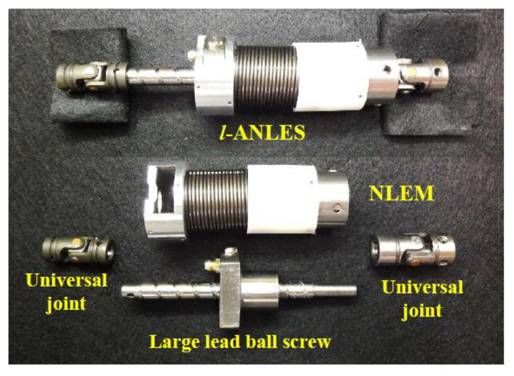
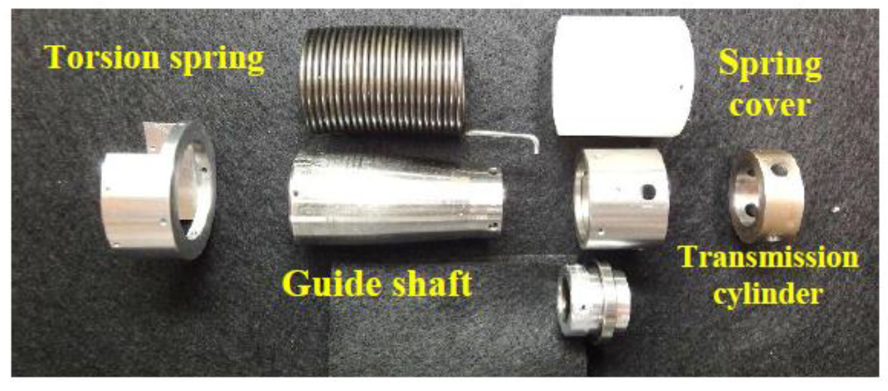
Figure 1 shows the structural parts and the assembled appearance of l-ANLES, consisting of a large lead ball screw and the Non-Linear Elasticity Module (NLEM). The NLEM consists of a guide-shaft, a torsion-spring and a transmission cylinder, as shown in Figure 2. The torque generated by the DC-motor rotates the ball screw rod that brings about the rotation or translation of the guide shaft that covers the ball screw nut. Rotation of the guide-shaft induces twisting of the torsion-spring. The diameter of the guide shaft smoothly thins down along the rotation axis so that the torsion-spring twists around the guide shaft from the edge of the wide diameter, yielding a non-linear elasticity as described below. The l-ANLES needs to transform the rotational motion to the translational motion, and vice versa, with minimum transmission loss. We therefore placed a large lead ball screw (10 mm diameter of the rod with a 10 mm lead) into the guide-shaft as shown in Figure 1.
Figure 1.
Assembled view and main parts of linear type Actuator with Non-Linear Elasticity System (l-ANLES).
Figure 1.
Assembled view and main parts of linear type Actuator with Non-Linear Elasticity System (l-ANLES).

Figure 2.
Non-Linear Elasticity Module (NLEM).

2.2. Structure and Design of r-ANLES
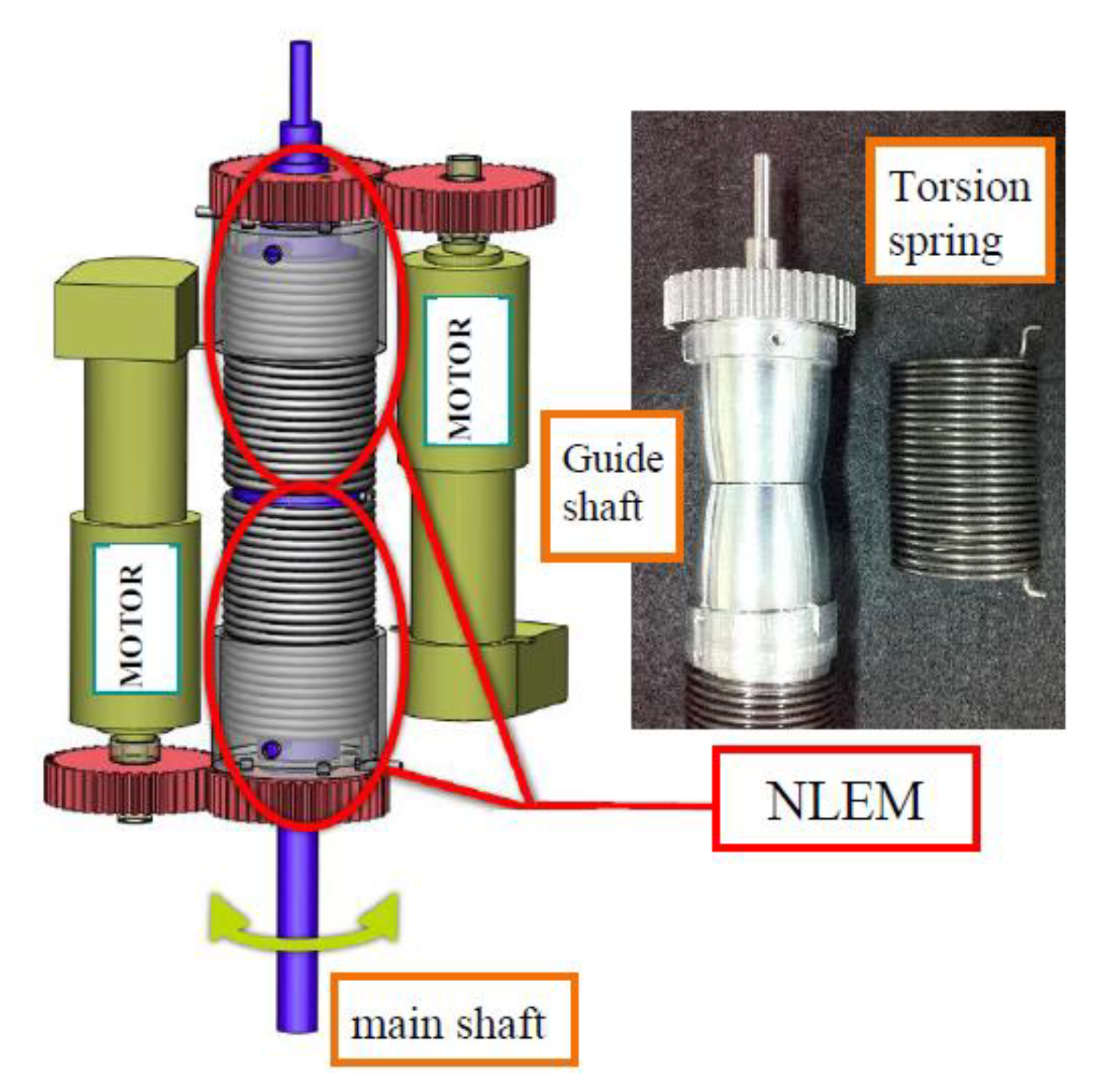
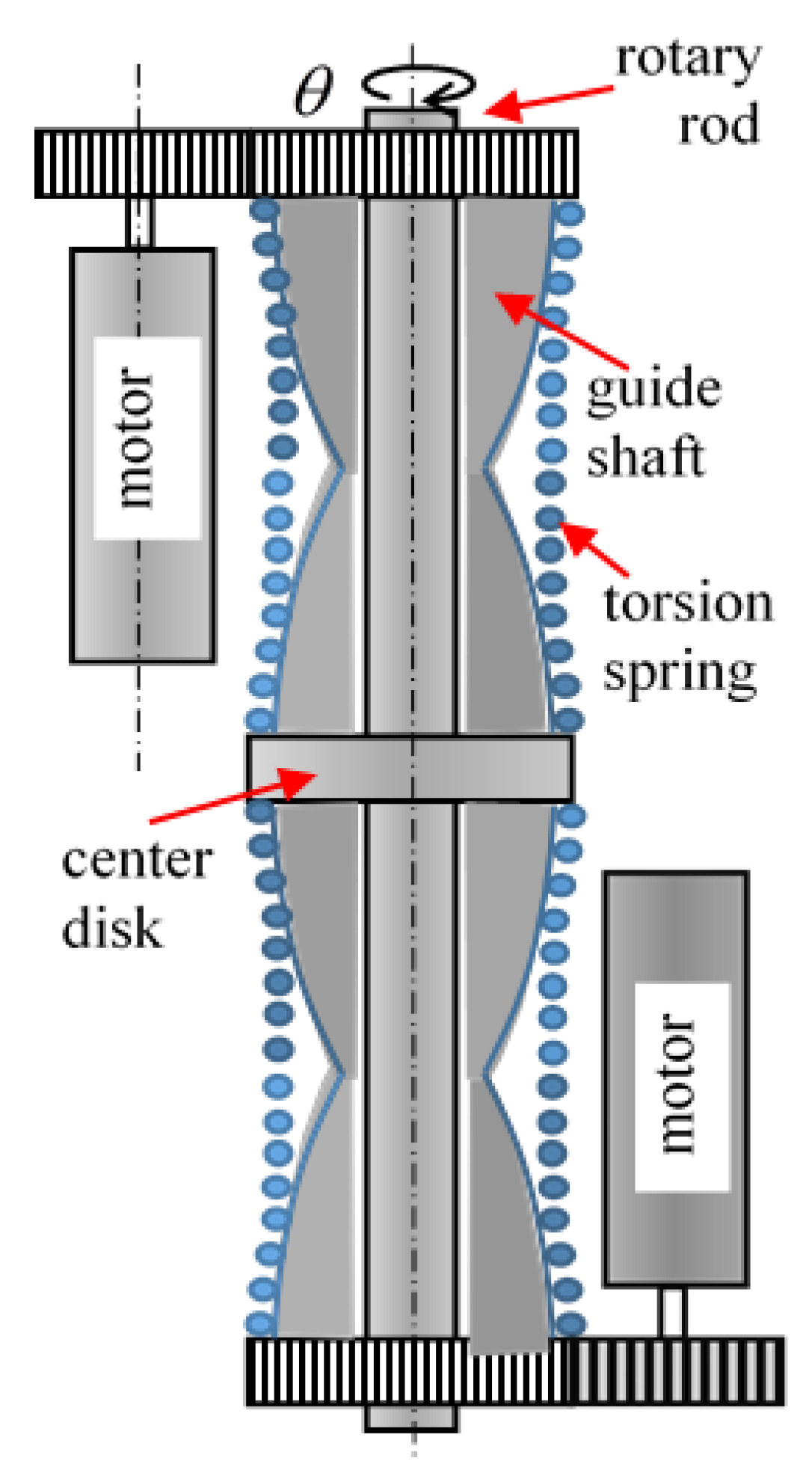
In r-ANLES, a pair of guide-shafts and torsion springs is allocated counteractively along the main shaft as shown in Figure 3. The torsion springs are twisted by the individual DC motor via the gear and wrap around the guide shaft. Therefore, it is apprehended that the r-ANLES is identical to the l-ANLES but lacked a transformation process between rotation and translation.
Figure 3.
Rotary type ANLES (r-ANLES).

As can be easily understood in the case of the r-ANLES, two motor rotations in opposite directions rotate the main shaft (Figure 3) with no twisted springs if the motors turn at precisely the same speed. Conversely, two motor rotations in an identical direction cause the springs to twist around the guide shafts with no rotation of the main shaft while strengthening its stiffness.
The same is equally true for l-ANLES.
2.3. Design of Non-Linear Elasticity
The non-linear elasticity of l-ANLES and r-ANLES can be rigorously designed by designing the shape of the guide shaft.
where, lr(x) is the developed length of the spring wire (the length of the spring wire in part of the axial portion of L − x in Figure 4) that actually works as a spring at location x. E is the modulus of the longitudinal elasticity and I is the second moment of the area of the torsion spring wire. Equation (1) leads the spring coefficient as a function of x,
∆Ta(x) = ﴾EI/lr(x)﴿∆ϕ
K(x) = ∆T(x)/∆ϕ = EI/lr(x)
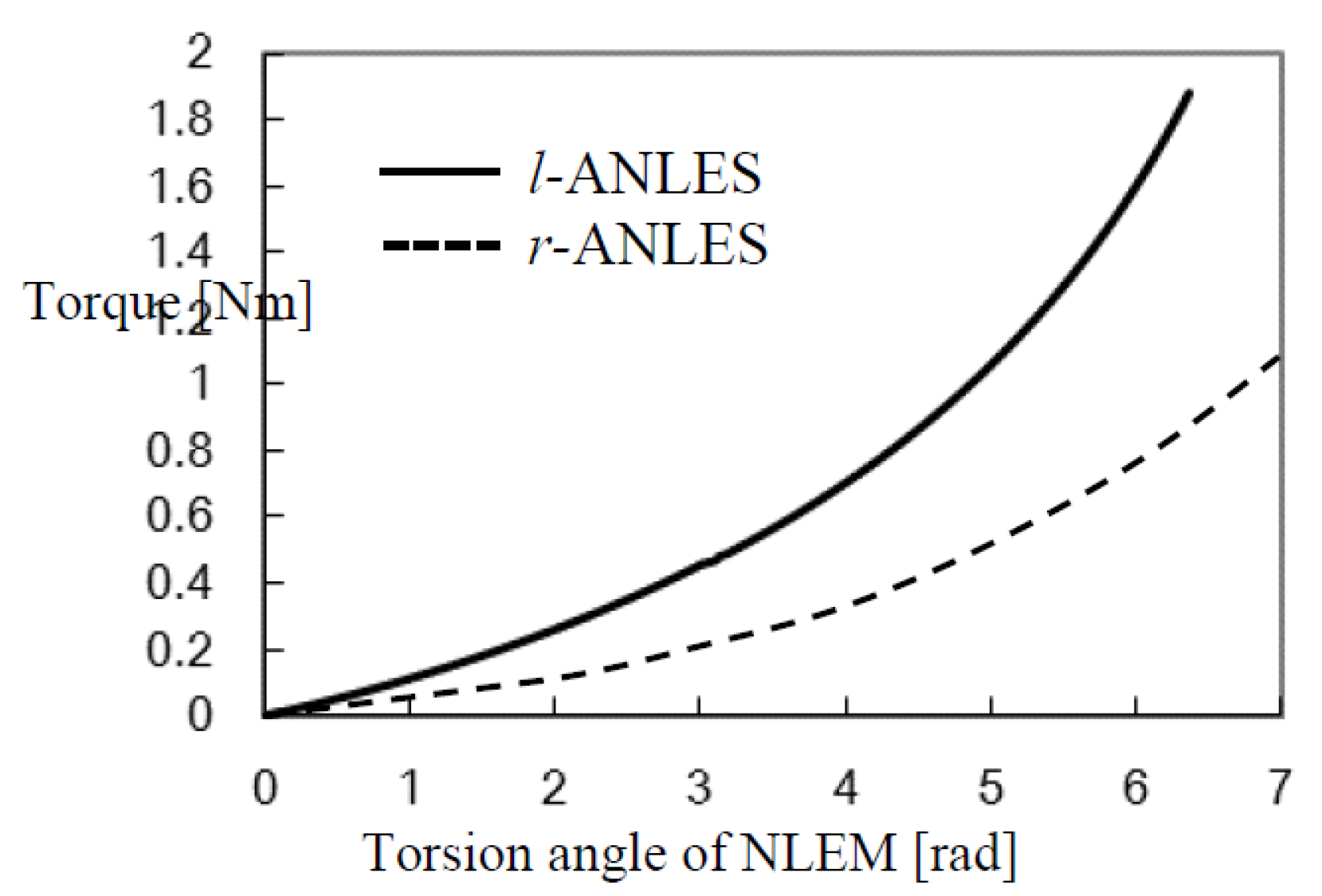
Through this equation, one can obtain the relation between the torsion angle ϕ(x) and the torque Ta(x) Hence, Ta(x) and K(x) may be denoted by Ta(ϕ) and, K(ϕ) respectively, in lieu of using the intermediate parameter x. Now we have a design-ability to obtain the function Ta(ϕ) by designing r(x), the radial function along the axis. Details of how to calculate Ta(ϕ) are described in Appendix A. Figure 5 shows the non-linear elasticity of the l-ANLES and the r-ANLES, which are designed according to required stiffness characteristics.
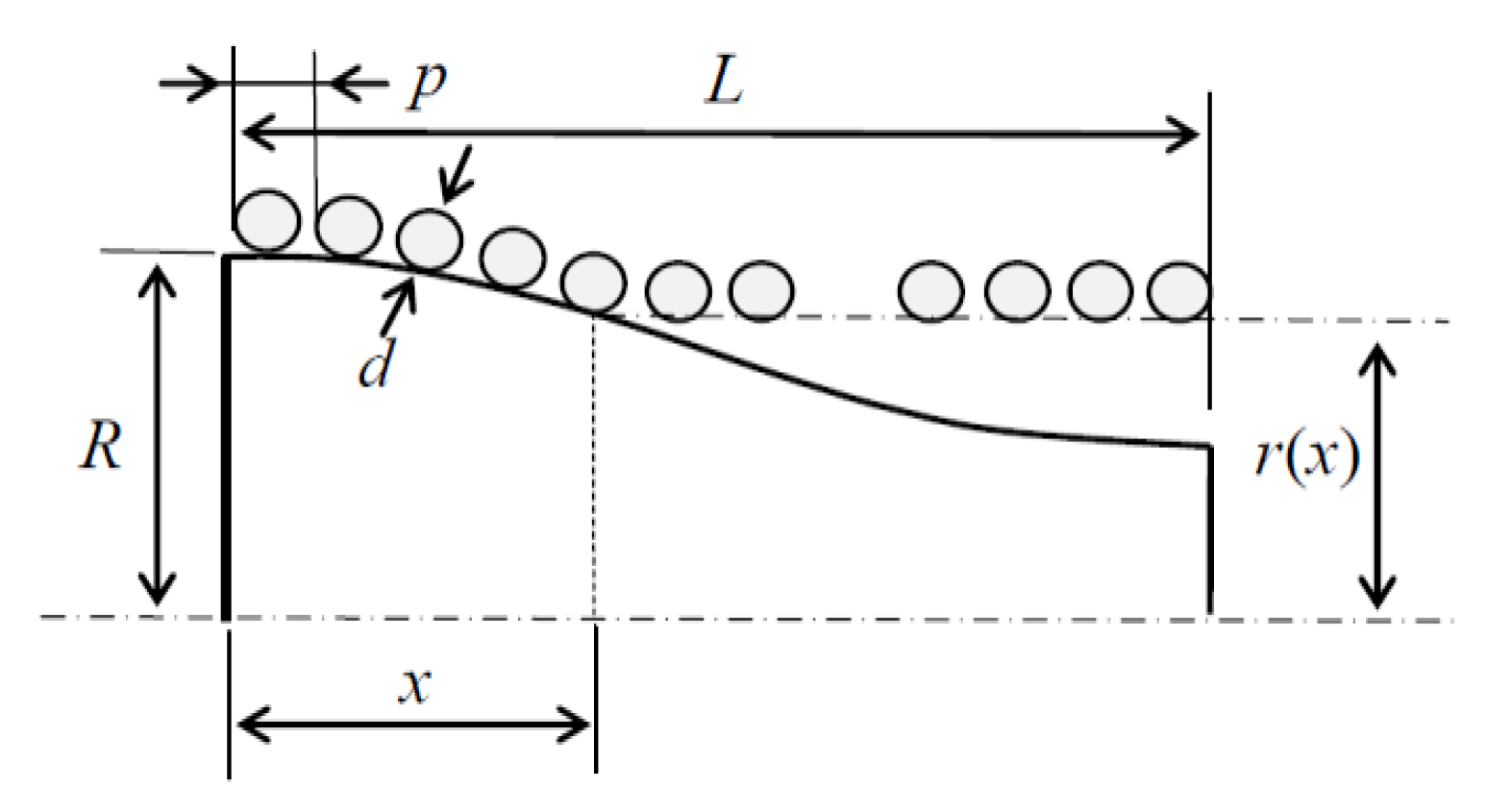
Figure 4.
Model of the guide-shaft.

Figure 5.
Non-linear elasticity of ANLES designed for elbow joint.

2.4. Stiffness of Rotary Joint
A. The case of l-ANLES
l-ANLES exerts a force vector that is also a function of the torsion angle of the spring such as,
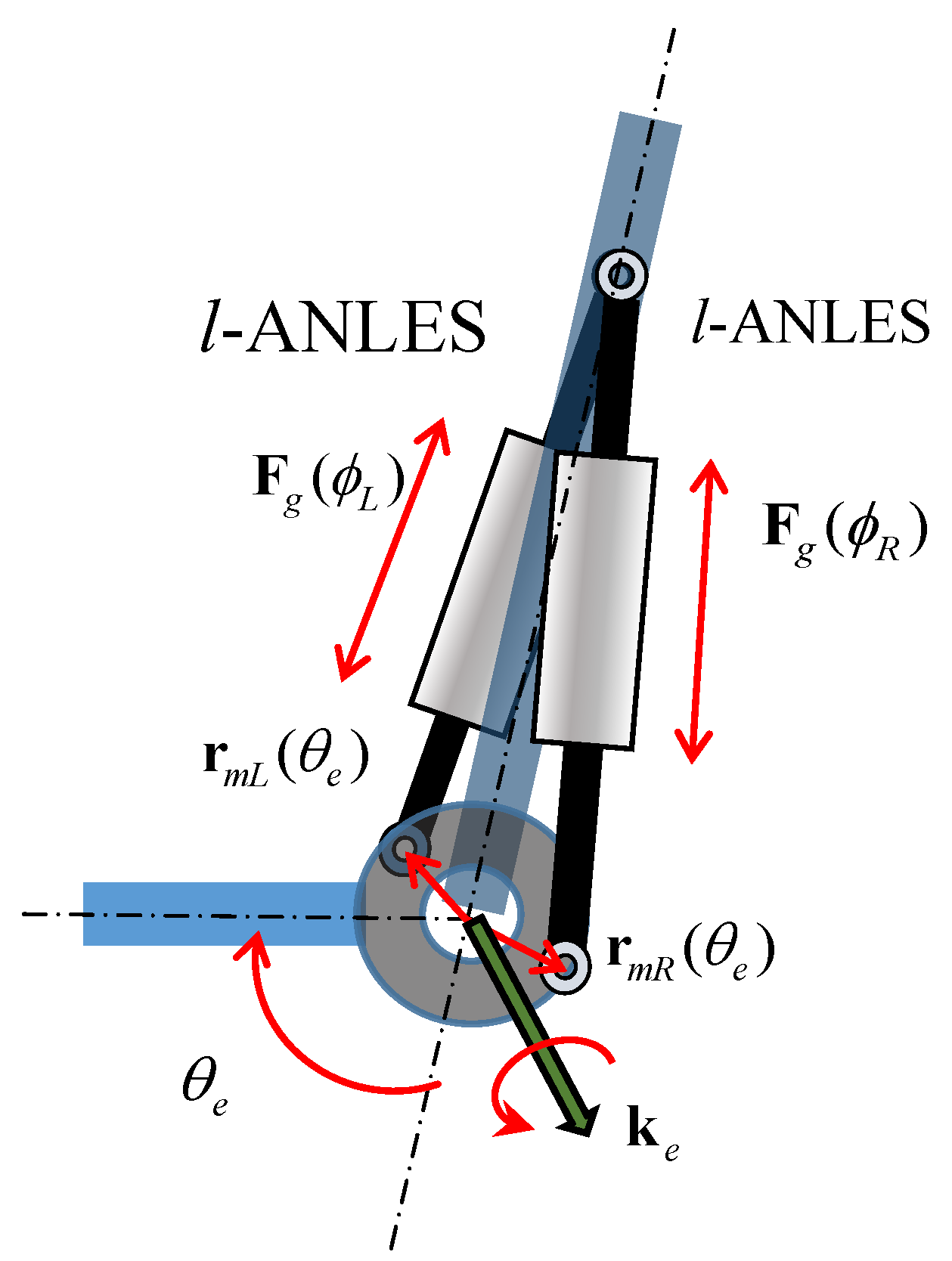
where, ld is the lead of the large lead ball screw (see Figure 1). ul(θe) is a unit vector along the rod axis of the l-ANLES, which depends on the joint angle θe A pair of l-ANLESes exerts forces individually that counteractively affect a rotary joint axis as a torque as follows,
where ke is a unit vector of the rotary joint and rmR(θe) and rmL(θe) are moment arm vectors from the rotary axis to force vectors of l-ANLES, which are functions of the joint angle θe (see Figure 6). Tg is a torque due to a whole gravitational effect and Text is a torque generated by contact with external objects. In Equation (4) Text is not considered because the aim is to develop a robotic joint in which stiffness can be set regardless of external forces or load torques on the joint.
Fl(ϕ) ≡ (2π/ld)Ta(ϕ)ul(θ)
Te = ke·﴾rmR(θe) × FlR(ϕR) − rmL(θe) × FlL(ϕl) ﴿ − Tg − Text
= (2π/ld)ke·(Ta(ϕR)rmR(θe) × ulR(θe) − Ta(ϕL)rmL(θe) × ulL(θe) ﴿ − Tg − Text
Figure 6.
A rotary joint controlled by a pair of l-ANLESes.

Let us consider an equilibrium state, in which the gravitational torque is compensated by the torques due to the l-ANLES.
Denoting
![Actuators 03 00124 i001]() where
where ![Actuators 03 00124 i002]() and
and ![Actuators 03 00124 i003]() are torsion angles of the l-ANLESes provided by the individual motors and ∆ϕR = ϕR −
are torsion angles of the l-ANLESes provided by the individual motors and ∆ϕR = ϕR − ![Actuators 03 00124 i002]() , ∆ϕL = ϕL −
, ∆ϕL = ϕL − ![Actuators 03 00124 i003]()

 and
and  are torsion angles of the l-ANLESes provided by the individual motors and ∆ϕR = ϕR − , ∆ϕL = ϕL −
 Assuming,
![Actuators 03 00124 i004]() an equilibrium state is produced as
an equilibrium state is produced as
![Actuators 03 00124 i005]() where ki (θe) = (2π/ld)ke·rmi(θe) × uli(θe), (i = R, or L)
where ki (θe) = (2π/ld)ke·rmi(θe) × uli(θe), (i = R, or L)


The stiffness of the rotary joint is defined as,
Se ≡ αTe/αθe [Nm/rad]
If we consider changing the joint stiffness under a constant joint angle ![Actuators 03 00124 i006]() , kR(
, kR( ![Actuators 03 00124 i006]() ) and kL(
) and kL( ![Actuators 03 00124 i006]() ) become constants. Therefore,
) become constants. Therefore,
![Actuators 03 00124 i007]()
 , kR( ) and kL( ) become constants. Therefore,

Since we can expect ![Actuators 03 00124 i008]() to always have opposite signs in a counteractive configuration, as shown in Figure 6, we can calculate the absolute value of Se as,
to always have opposite signs in a counteractive configuration, as shown in Figure 6, we can calculate the absolute value of Se as,
![Actuators 03 00124 i009]() where
where ![Actuators 03 00124 i010]() are positive constant values under a constant joint angle
are positive constant values under a constant joint angle ![Actuators 03 00124 i006]() Equation (9) suggests that the joint stiffness can be adjusted by setting
Equation (9) suggests that the joint stiffness can be adjusted by setting ![Actuators 03 00124 i002]() and
and ![Actuators 03 00124 i003]() under holding Equation (6), and that the non-linearity of Ta(ϕ) is indispensable for the joint stiffness to be varied, because if Ta(ϕ) is linear with respect to ϕ, ∂Ta(ϕ)/∂ϕ takes a constant value, which means the stiffness Se is also constant regardless of ϕ.
under holding Equation (6), and that the non-linearity of Ta(ϕ) is indispensable for the joint stiffness to be varied, because if Ta(ϕ) is linear with respect to ϕ, ∂Ta(ϕ)/∂ϕ takes a constant value, which means the stiffness Se is also constant regardless of ϕ. ![Actuators 03 00124 i002]() and
and ![Actuators 03 00124 i003]() will be subject to gravitational effects as described above, which might narrow the adjustable range of stiffness. A weight compensator introduced in the upper arm, described in the following section, will alleviate this problem.
will be subject to gravitational effects as described above, which might narrow the adjustable range of stiffness. A weight compensator introduced in the upper arm, described in the following section, will alleviate this problem.
 to always have opposite signs in a counteractive configuration, as shown in Figure 6, we can calculate the absolute value of Se as,

 are positive constant values under a constant joint angle Equation (9) suggests that the joint stiffness can be adjusted by setting and under holding Equation (6), and that the non-linearity of Ta(ϕ) is indispensable for the joint stiffness to be varied, because if Ta(ϕ) is linear with respect to ϕ, ∂Ta(ϕ)/∂ϕ takes a constant value, which means the stiffness Se is also constant regardless of ϕ. and will be subject to gravitational effects as described above, which might narrow the adjustable range of stiffness. A weight compensator introduced in the upper arm, described in the following section, will alleviate this problem.
B. The case of r-ANLES
Stiffness regulation in the case of r-ANLES is simple. Figure 7 shows a configuration of a pair of r-ANLESes to control the rotation and stiffness of a rotary rod. The motors rotate guide shafts via gears, which twist torsion springs. One end of the springs is connected to the center disk that rotates together with the rotary rod. Therefore torques generated by the torsion springs are directly transmitted to the rotary rod. Torque loaded to the rotary rod is,
where, Ta(ϕU) and Ta(ϕL) are torques generated by upper-side and lower side r-ANLESes respectively. If we can neglect the gravitational effect, torsion angles ϕU and ϕL actually take the same value in an equilibrium state. Therefore, let us denote ϕU = ϕL = ϕe
Te = Ta(ϕU) − Ta(ϕL)
The stiffness around the rotary joint is then calculated by,
![Actuators 03 00124 i011]() where θ is the rotation angle of the rotary rod and α is a transmission ratio between θ and the torsion angle of r-ANLES ϕ (for the configuration shown in Figure 7, α = 1).
where θ is the rotation angle of the rotary rod and α is a transmission ratio between θ and the torsion angle of r-ANLES ϕ (for the configuration shown in Figure 7, α = 1).

Figure 7.
Rotary joint controlled by a pair of r-ANLES.

3. Two-DOF Upper Arm
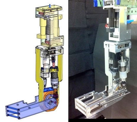
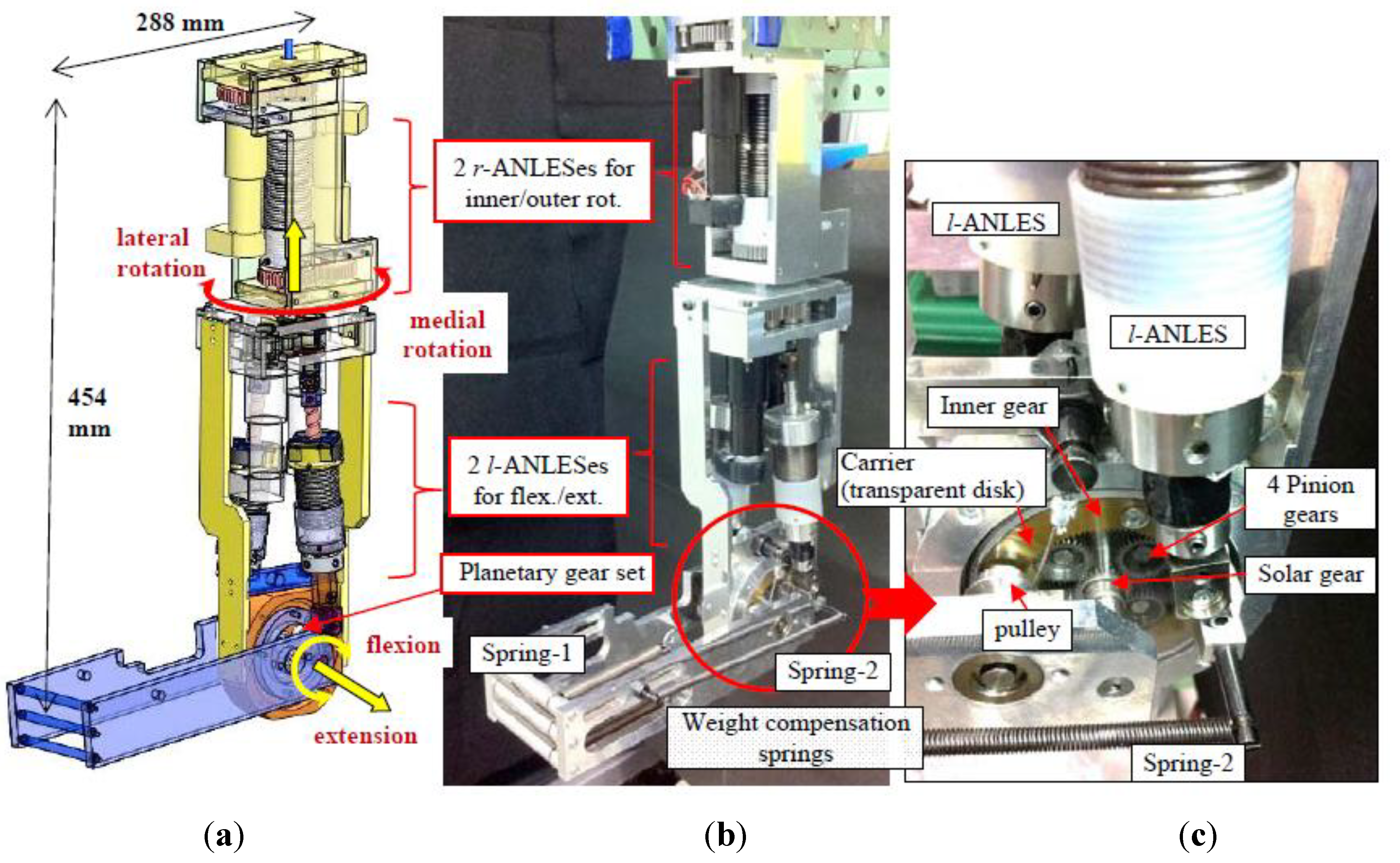
Figure 8a shows the structure of the upper limb. It has two DOFs: the flexion/extension of the elbow and the lateral/medial rotation of the upper arm. A pair of l-ANLESes controls the flexion/extension of the elbow. The lateral/medial rotation is controlled by a pair of r-ANLESes. Figure 8b shows the assembled view of the arm. The weight is about 6 kg. Table 1 shows the specifications of the motors and the spring used in the ANLESes.
It is possible to use r-ANLESes for driving the flexion/extension by using bevel gears to change the rotary axes of the r-ANLESes. This requires a robust housing to sustain the axis rods and the bevel gears at both sides of the elbow joint, which might cause an increase in the weight and the moment of the arm’s inertia.

| axis | Flexion/Extension | Lateral/Medial Rotation | ||
|---|---|---|---|---|
| Actuator ( Motor ) | Maxon RE25 × 2 Blushless DC 20 W Stall torque 250 mNm | Faulhaber 3257 × 2 Blushless DC 80 W Stall torque 540 mNm | ||
| Reduction gear ratio | 132 | 134 | ||
| Sensor (Rotary Encoder) | Maxon HEDS 5540 × 2 | Faulhaber IE2-16 × 2 | ||
| spring | modulus of longitudinal elasticity | 1.86 × 10⁵ [N/mm2] | ||
| Wire diameter | 1.9 mm | 4.0 mm | ||
| Coil diameter | 32.7 mm | 36 mm | ||
| Number of coiling | 24 | 15 | ||
| pitch | 2.0 mm | 4.2 mm | ||
Figure 8.
(a). Structure of the two- degree-of-freedom (DOF) upper arm; (b). Assembled view of the two-DOF upper arm; (c). Assembled view of the elbow joint part.
Figure 8.
(a). Structure of the two- degree-of-freedom (DOF) upper arm; (b). Assembled view of the two-DOF upper arm; (c). Assembled view of the elbow joint part.

3.1. Elbow Joint
The elbow joint mainly consists of a planetary gear set (PGS) (see Figure 8c). The inner gear of the PGS is connected to the upper arm and the solar gear is connected to the forearm. Two carriers are equipped at both sides of the PGS, which support the four rotary axes of the pinion gears. Each carrier is connected to the l-ANLES, on which connecting points are located so that two l-ANLESes work counteractively, as shown in Figure 8a,b. The rotation of the motor of l-ANLES in one side in the opposite direction to that of the motor in other side brings about prismatic motions of two ball screw rods in mutually opposite directions, providing a rotation of the carrier (transparent disks shown in Figure 8c) of at most 52 deg. However, it is transmitted to the solar gear’s rotation (and, therefore, the forearm’s rotation) about three times larger due to the speed-up ratio of the PGS (teeth number of the inner gear/teeth number of the solar gear), resulting in about a 160-degree rotation of the elbow joint, which is almost equal to the rotation range of a human elbow (approximately 140° [35]). The rotation of the l-ANLES motors by the same angle in the same direction provides the same amount of traction force of the ball screw rods, which induces the same amount of torque in the opposite direction of the elbow joint because of the antagonistic configuration of the two l-ANLESes. Therefore, they counterbalance without the elbow joint’s rotation. However, concomitantly, the torsion spring of each l-ANLES wraps around the guide shaft by the motor rotation, which augments the stiffness of the elbow joint, as verified in the experiments described below.
3.2. Lateral/Medial Rotation of the Upper Arm
A pair of r-ANLESes controls the lateral/medial rotation of the upper arm (see Figure 3, Figure 8a,b). The rotations of the r-ANLES motors in mutually opposite directions bring about the lateral/medial rotation of the arm, of which the rotation angle is not limited unless the motion of the forearm or the upper arm is not hampered by obstacles. The rotations in the same direction twist the two torsion springs in mutually opposite directions, enhancing the stiffness around the lateral/medial axis, as verified by the experiments described below.
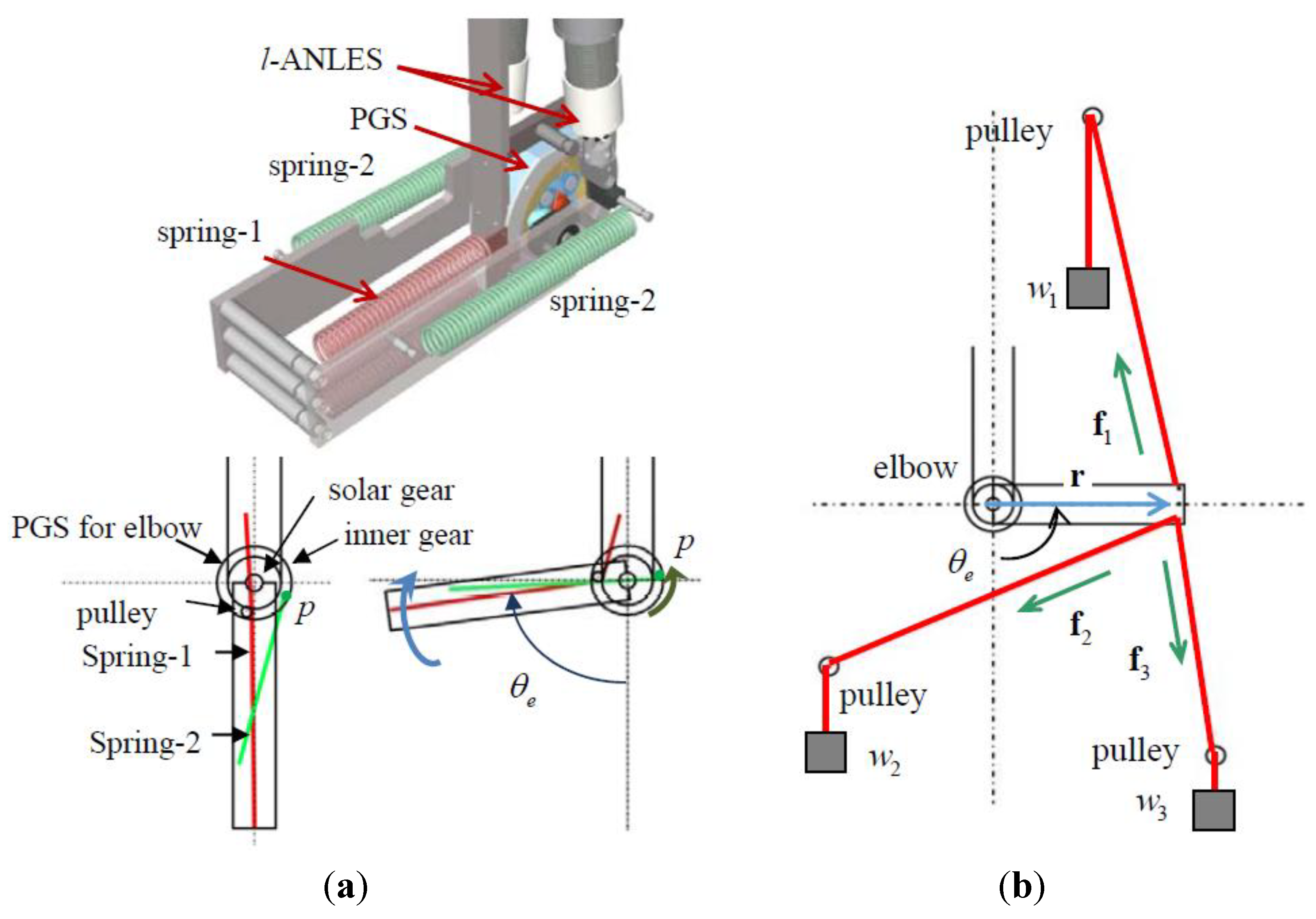
3.3 Weight Compensator
The weight of the forearm is compensated by the weight compensation springs shown in Figure 8a and Figure 8b. The weight compensation is indispensable because if it is absent, l-ANLESes have to sustain all of the forearm weight. This requires some pre-torsion of the springs of the l-ANLES, the amount of which depends on the elbow angle. Therefore, a lack of the weight compensator will deteriorate the controllability of the joint stiffness by l-ANLES.
Figure 9a shows the spring alignment. Spring-1 is connected between the upper arm and the forearm via the pulley as shown in Figure 8b,c. Spring-2 is connected between the forearm and the inner gear of the PGS as also shown in Figure 8b,c. A successful aspect of this weight compensation mechanism resides in the fact that the inner gear rotates in the opposite direction to the solar gear’s rotation (therefore, the forearm’s rotation). Hence, the connecting point p at the inner gear of Spring-2 transfers, as shown in Figure 9a, so that it passes to the axis of the elbow joint, which changes the sign of the loaded torque due to Spring-2.
Figure 9b shows the experimental apparatus to the load torque that is necessary for the elbow joint to take a specified angle. Three weights pull the distal end of the forearm via wires and pulleys to give an appropriate torque about the elbow joint in any joint angle. Procedures of the experiments are as follows.
- (1)
- The weights w1, w2 and w3 are adjusted so that the elbow joint takes a specified joint angle θe that is measured by the optical encoder attached to the rotary axis of the elbow joint.
- (2)
- Then, the torque loaded around the elbow joint is measured bywhere, r = [rx ry]T is a vector from the elbow joint to the distal end of the forearm, and fi = [fix fiy]T, (i = 1,2,3) is force vectors generated by the weights.τe = rx(f1y + f2y +f3y) − ry(f1x + f2x + f3x)
Figure 9.
(a) Placement of the weight compensation springs. (b) Experimental apparatus for the weight compensator.
Figure 9.
(a) Placement of the weight compensation springs. (b) Experimental apparatus for the weight compensator.

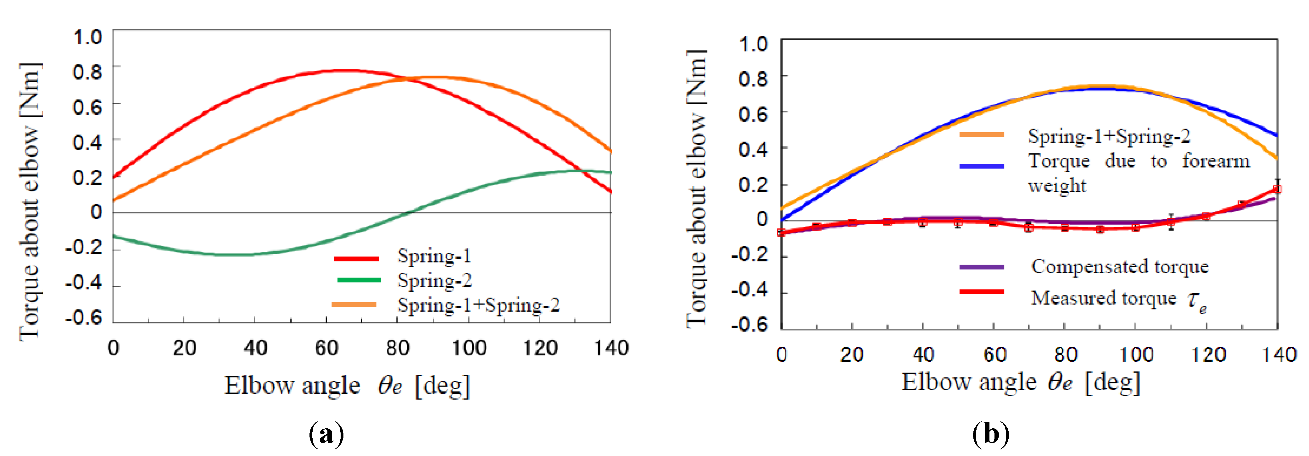
Figure 10.
Theoretical and Experimental result of weight compensation of the forearm. (a) Torques at the elbow joint due to springs; (b) Torques at the elbow joint due to springs, forearm weight and their compensating weights.
Figure 10.
Theoretical and Experimental result of weight compensation of the forearm. (a) Torques at the elbow joint due to springs; (b) Torques at the elbow joint due to springs, forearm weight and their compensating weights.

As shown in Figure 10a, the torque exerted by Spring-2 changes from a negative value to a positive one as the elbow flexes, since Spring-2 crosses over the elbow axis due to the rotation of the inner gear. Hence, the resultant torque of Spring-1 and Spring-2 effectively compensates the torque due to the forearm weight, as shown with the line labeled “Compensated torque” in Figure 10b. The compensated torque takes a nearly zero value throughout the whole range of the elbow angle, which is verified by measuring the torque of the elbow joint as shown in Figure 10b. Figure 10b also shows error bars of the data variation of five trials of identical experiments, but they are less visible because of such good repeatability of the experiments.
Figure 10b also shows that the torque due to the weight of the forearm is not entirely compensated, especially in the ranges of the elbow joint angle less than 20° and more than 120°. These residual torques are loaded on a l-ANLES and required some pre-torsion of the torsion spring of the l-ANLES to hold the specified elbow joint angle. However, it does not harm the performance of the arm as a whole because the value of the non-compensated torque is so small, and because it would be uncommon for the arm to do dexterous jobs requiring stiffness regulation in such ranges of the elbow joint angles.
The lateral/medial joint has not yet been equipped with a weight compensator, which will be required when the arm is connected to a shoulder joint of which the rotation will engender a torque due to gravitational force around the lateral/medial joint of the arm. This will also require a change in the weight compensation around the elbow joint according to the shoulder joint angles.
3.4. Stiffness Control of the Flexion/Extension Axis and the Lateral/Medial Rotation Axis
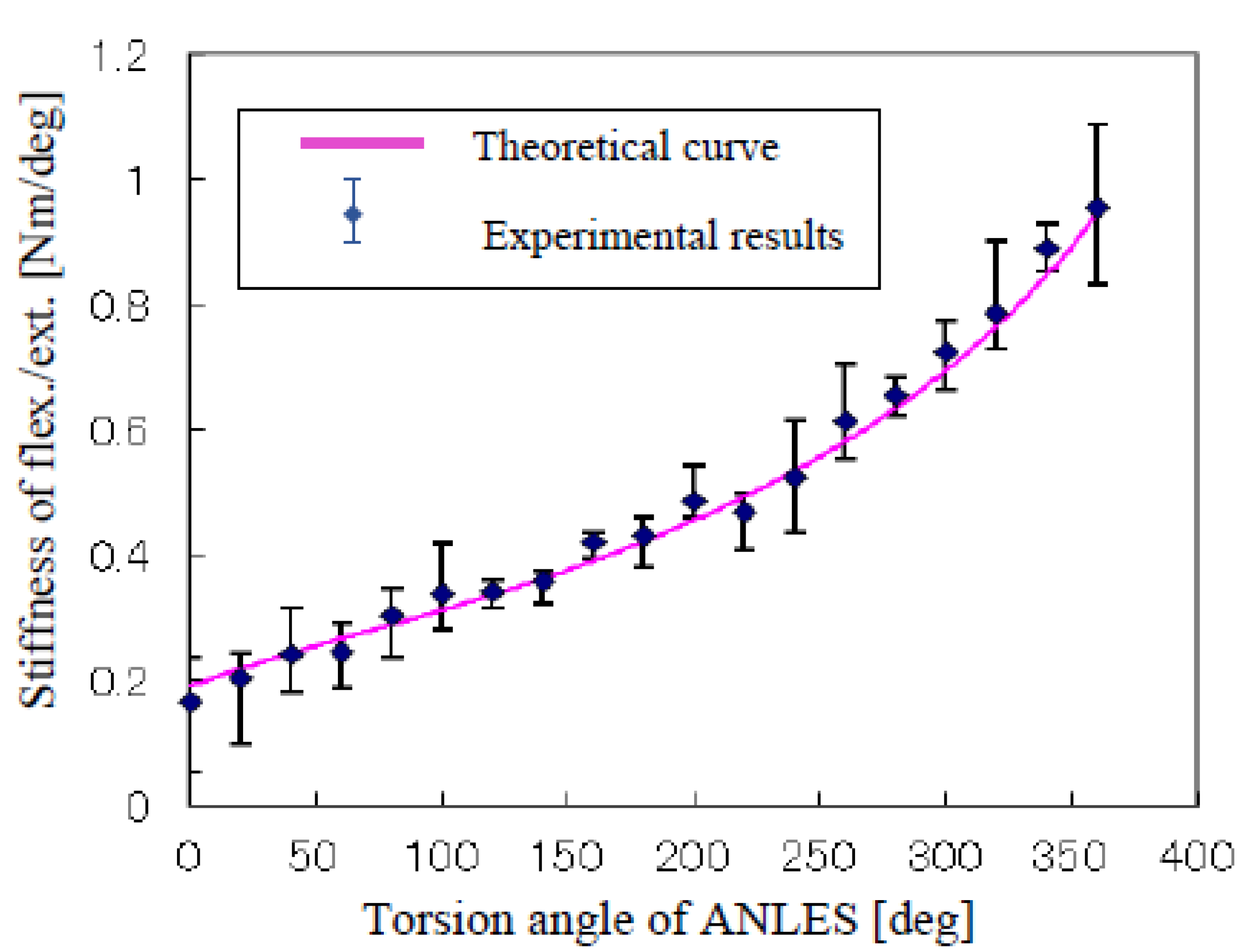
The stiffness of the flexion/extension axis of the elbow joint and the lateral/medial rotation axis of the upper arm can be controlled in an antagonistic action of a pair of l-ANLESes and r-ANLESes, respectively. The same amount of twisting of the torsion springs in both ANLESes changes the stiffness of the joint. Figure 11 and Figure 12 show the results of the experimental measurement of the stiffness accompanied by a theoretical curve. “Torsion angle of ANLES” in the horizontal axis refers to the same amount of rotation angle of the motors of a pair of ANLESes rotating the guide-shafts.
The experimental procedures are as follows:
- (1)
- The non-linear elasticity of the ANLES obeys the one shown in Figure 5.
- (2)
- Two motors of the l-ANLESes are rotated so that the elbow angle reaches 90° and two motors of the r-ANLESes are rotated so that the lateral/medial rotation angle reaches 0 deg. The motors of the l-ANLESes and r-ANLESes are controlled by a normal PID controller.
- (3)
- In the above state, the torsion angles of both l-ANLESes and r-ANLESes are almost zero because the pre-torsion of ANLESes to sustain the forearm weight is not needed due to the weight compensator.
- (4)
- The motors of the l-ANLESes or the r-ANLESes are rotated by the same angle to give the torsion springs of the l-ANLESes or the r-ANLESes the same amount of torsion angle in order to increase the stiffness of the elbow or the lateral/medial joint.
- (5)
- A weight W was loaded at the forearm tip downward in the case of the elbow joint, or horizontally in the case of the lateral/medial rotation axis. The weight was adjusted to attain a 5-degree rotation of the joint that is measured by the optical encoder and displayed on the computer screen in each setting of the torsion angle of ANLESes. Then, the stiffness is obtained as: (Nm/rad) with the forearm length l.
The load torque is hardly changed by the 5-degree rotation of the joints (only 0.4% reduction). This reduction is completely decreased when a smaller rotation angle is given. However, the load torque becomes closer to the friction torque of the joints if a smaller rotation angle is given, bringing about a wide variation of stiffness data.
Figure 11.
Stiffness about flexion/extension of the elbow joint.

Figure 12.
Stiffness about the lateral/medial rotation of the upper-arm.
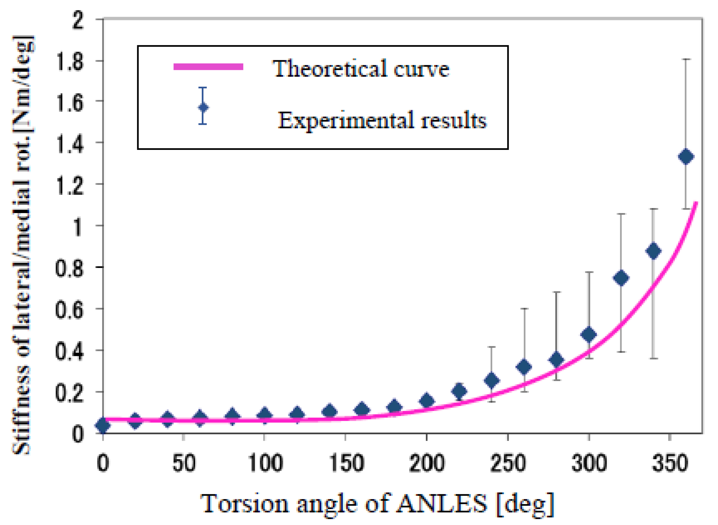
We achieved the same experimental results five times according to the procedure described above. The error bars in Figure 11 and Figure 12 show their data variation, as well as the measured stiffness, which shows much variation as the torsion angle of ANLESes increases. This is due to friction yielding between the torsion spring and the guide-shaft of ANLESes. When the spring is twisted and coiled on the guide-shaft, the spring wire has to be moved slightly on the guide-shaft because the pitch narrows.
The result shown in Figure 11 and Figure 12 elucidates the validity of our theory since the experimental data coincided well with the theoretical curve. The cause of the experimental data being a little higher than the theoretical curve is due to the friction that emerged during torque transmission with gears or bearings.
4. Conclusions
In this paper, a two-DOF upper arm with a musculo-skeletal structure is introduced, in which the ANLES works as a voluntary muscle. Two types of ANLESes are used for controlling the joint angle and joint stiffness in the flexion/extension of the elbow joint and lateral/medial flexion of the upper arm: the linear type ANLES (l-ANLES) and the rotary type ANLES (r-ANLES), respectively. Combined with our previous study in which two types of ANLES were used in a wrist joint [31,32,33], the present study clarifies that ANLES can be used as actuators in a wide range of robots driven on the basis of antagonistic actuations.
Advantages of using ANLES are as follows:
- (1)
- The magnitude and the adjustable range of joint stiffness can be precisely designed by designing the shape of the guide-shaft.
- (2)
- No particular kind of non-linear elastic elements are necessary to construct the ANLES.
We are now constructing a two-DOF shoulder joint that is also driven by ANLESes and plan to combine the upper arm to constitute a four-DOF arm. Subsequently, we plan to combine the four-DOF arm with the three-DOF wrist joint that has been completed to construction [34], which will provide a seven-DOF manipulator controlled in an antagonistic manner similar to the human upper extremity.
Acknowledgments
The authors thank the Japan Society for the Promotion of Science, via Grants-in-Aid for Scientific Research: No. 18560258 “Stiffness control of an antagonistically driven joint using the actuator with non-linear elasticity” for their support in the pursuance of this work.
Conflicts of Interest
The author declares no conflict of interest.
Appendix A
Let us assume that the spring is twisted and wraps on the guide shaft from the left edge to the position x along the guide shaft axis (see Figure 4). The developed length of the spring portion that wraps on the guide shaft by the axial location x: la(x) is calculated as,
![Actuators 03 00124 i012]() where, r(x) is a radius of the spring at x with r(0)=R, which is designed as a differentiable function about x. p(x) is the pitch of the spring that is getting to shorten as the twisting advances. Therefore it is also a function of x. The coiling number n(x) in
where, r(x) is a radius of the spring at x with r(0)=R, which is designed as a differentiable function about x. p(x) is the pitch of the spring that is getting to shorten as the twisting advances. Therefore it is also a function of x. The coiling number n(x) in
![Actuators 03 00124 i013]() where, lT is a total developed length of the spring. Hence the pitch when the spring wraps by position x is calculated as,
where, lT is a total developed length of the spring. Hence the pitch when the spring wraps by position x is calculated as,
![Actuators 03 00124 i014]()


Differentiating (A-1) with respect to x, we have,
![Actuators 03 00124 i015]()

Substituting p(x) that is obtained from algebraic operation of (A-3)
dla(x)/dx = ﴾lT − la(x) ﴿/(L − x)
Solving (A-5) with an initial value: la(0) = 0, we have
la(x) = (lT / L)x
Surprisingly, la is linear with respect to x and does not depend on r(x).
d la(x) is also related to the wrapping angle of the spring η(x) is,
![Actuators 03 00124 i016]()

The wrapping angle means a winding angle of the spring portion that wraps on the guide shaft by the axial location x. (A-7) leads,
![Actuators 03 00124 i017]()

Substituting dla(x)/dx = lT / L that is obtained from (A-6), we have,
![Actuators 03 00124 i018]()

Substituting p(x) that is obtained from (A-3) and integrating (A-9) with an initial condition η(0) = 0, we have η(x).
Then the torsion angle ϕ(x) is obtained by a difference between η(x) and the winding angle in the state of the spring not wrapping on the guide-shaft,
ϕ(x) = η(x) − 2πx/p(0)
Additional torque necessary to twist dϕ(x) from a current torsion angle ϕ(x) is inversely proportional to the expansion length of the spring lT − la(x) as follows;
![Actuators 03 00124 i019]() where, E is the modulus of longitudinal elasticity and I is the second moment of area of the torsion spring wire. Substituting ϕ(x) from (A-9) we have,
where, E is the modulus of longitudinal elasticity and I is the second moment of area of the torsion spring wire. Substituting ϕ(x) from (A-9) we have,
![Actuators 03 00124 i020]()


Integrating (A-12) with Ta(0) = 0 and combined with the result of (A-10) we have Ta(ϕ) without using an intermediate variable x.
References
- Shadmehe, R.; Arbib, M.A. A mathematical analysis of the force-stiffness characteristics of muscles in control of a single joint system. Biol. Cybern. 1992, 66, 463–477. [Google Scholar] [CrossRef]
- Matthews, P.B.C. The dependence of tension upon extension in the stretch reflex of the soleus muscle of the decerebrated cat. J. Physiol. 1959, 147, 521–546. [Google Scholar]
- Fel’dman, A.G. Functional tuning of the neurons system with control of movement or maintenance of a steady posture. Biofizika 1966, 11, 498–508. [Google Scholar]
- Hoffer, J.A.; Andrearsen, S. Regulation of soleus muscle stiffness in premammiliary cats. J. Neurophysiol. 1981, 45, 267–285. [Google Scholar]
- Dolan, J.M.; Friedman, M.B.; Nagurka, M.L. Dynamic and Loaded Impedance of Human Arm Posture. IEEE Trans. Syst. Man Cybern. 1993, 23, 698–709. [Google Scholar] [CrossRef]
- Mussa-Ivaldi, N.H.; Bizzi, E. Neural, Mechanical, and Geometrical Factors Subserving Arm Posture in Humans. J. Neurosci. 1985, 5, 2732–2743. [Google Scholar]
- Jocobsen, S.C.; Wood, J.E.; Knutti, D.F.; Biggers, K.B. The UTAH/M.I.T. Dexterous Hand: Work in Progress. Int. J. Rob. Res. 1984, 3, 21–51. [Google Scholar] [CrossRef]
- Jacobsen, S.C.; Ko, H.; Inversen, E.K.; Davis, C.C. Antagonistic Control of a Tendon Driven Manipulator. In Proceedings of the 1989 IEEE International Conference on Robotics and Automation, Scottsdale, AZ, USA, 14–19 May 1989.
- Laurin-Kovitz, K.F.; Colgate, J.E.; Carnes, S.D.R. Design of Components for Programmable Passive Impedance. In Proceedings of the 1991 IEEE International Conference on Robotics and Automation, Sacramento, CA, USA, 9–11 April 1991.
- Yi, B.J.; Freeman, R.A. Geometric Characteristics of Antagonistic Stiffness In Redundantly Actuated Mechanisms. In Proceedings of the 1993 IEEE International Conference on Robotics and Automation, Atlanta, GA, USA, 2–6 May 1993.
- Kobayasi, H.; Hyoudou, K.; Ogane, D. On Tendon-Driven Robotics Mechanisms with Redundant Tendons. Int. J. Rob. Res. 1998, 17, 561–571. [Google Scholar] [CrossRef]
- Lee, Y.T.; Choi, H.R.; Chung, W.K.; Youm, Y. Stiffness Control of a Coupled Tendon-Driven Robot Hand. IEEE Contr. Syst. Mag. 1994, 14, 10–19. [Google Scholar]
- Yi, B.J.; Freeman, R.A. Synthesis of Actively Adjustable Springs by Antagonistic Redundant Actuation. J. Dyn. Syst. Meas. Contr. 1992, 114, 454–461. [Google Scholar] [CrossRef]
- Chen, S.F.; Kao, I. Conservative Congruence Transformation for Joint and Cartesian Stiffness Matrices of Robotic Hands and Fingers. Int. J. Rob. Res. 2000, 19, 835–847. [Google Scholar] [CrossRef]
- Tondu, B.; Lopez, P.M. Modeling and Control of McKibben Artificial Muscle Robot Actuators. IEEE Contr. Syst. Mag. 2000, 20, 15–28. [Google Scholar] [CrossRef]
- Tondu, B.; Ippolito, S.; Guiochet, J.; Daidie, A. A Seven-degrees-of-Freedom Robot-arm Driven by Pneumatic Artificial Muscles for Humanoid Robots. Int. J. Robot. Res. 2005, 24, 257–274. [Google Scholar] [CrossRef]
- Verrelst, B.; Van Ham, R.; Vanderborght, B.; Daerden, F.; Lefeber, D.; Vermeulen, J. The Pneumatic Biped “Lucy” Actuated with Pleated Pneumatic Artificial Muscles. Autonom. Rob. 2005, 18, 201–213. [Google Scholar] [CrossRef]
- Koganezawa, K.; Watanabe, Y.; Shimizu, N. Antagonistic Muscle-Like Actuator and Its Application to Multi-DOF Forearm Prosthesis. Adv. Rob. 1999, 12, 771–789. [Google Scholar] [CrossRef]
- Migliore, S.A.; Brown, E.A.; DeWeerth, S.P. Biologically Inspired Joint Stiffness Control. In Proceedings of the 2005 IEEE International Conference on Robotics and Automation, Barcelona, Spain, 18–22 April 2005; pp. 4508–4517.
- Tonietii, G.; Schiavi, R.; Bicchi, A. Design and Control of a Variable Stiffness Actuator for Safe and Fast Physical Human/Robot Interaction. In Proceedings of the 2005 IEEE International Conference on Robotics and Automation, Barcelona, Spain, 18–22 April 2005; pp. 526–531.
- Schiavi, R.; Grioli, G.; Sen, S.; Bicchi, A. VSA-II: A Novel Prototype of Variable Stiffness Actuator for Safe and Performing Robots Interacting with Humans. In Proceedings of the 2008 IEEE International Conference on Robotics and Automation, Pasadena, CA, USA, 19–23 May 2008; pp. 2171–2176.
- Wolf, S.; Hirzinger, G. A New Variable Stiffness Design: Matching Requirements of the Next Robot Generation. In Proceedings of the IEEE International Conference on Robotics and Automation, Pasadena, CA, USA, 19–23 May, 2008; pp. 1741–1746.
- Haddadin, S.; Albu-Schaffer, A.; Hirzinger, G. The Role of the Robot Mass and Velocity in Physical Human-Robot Interaction-Part 2: Constrained Blunt Impacts. In Proceedings of the IEEE International Conference on Robotics and Automation (ICRA2008), Pasadena, CA, USA, 19–23 May 2008; p. 1339.
- Ham, R.; Sugar, T.G.; Vanderborght, B.; Hollander, K.W.; Lefeber, D. Compliant Actuator Design. IEEE Rob. Autom. Mag. 2009, 16, 81–94. [Google Scholar] [CrossRef]
- Ham, V.; Vanderborght, B.; Van Damme, M.; Verrelst, B.; Lefeber, D. MACCEPA, the Mechanically Adjustable Compliance and Controllable Equilibrium Position Actuator: Design and Implementation in a Biped Robot. Rob. Autonom. Syst. 2007, 55, 761–768. [Google Scholar] [CrossRef]
- Schiavi, R.; Grioli, G.; Sen, S.; Bicchi, A. VSA-II: A Novel Prototype of Variable Stiffness Actuator for Safe and Performing Robots Interacting with Humans. In Proceedings of the IEEE International Conference on Robotics and Automation, Pasadena, CA, USA, 19–23 May 2008; pp. 2171–2176.
- Wolf, S.; Hirzinger, G. A New Variable Stiffness Design: Matching Requirements of the Next Robot Generation. Proceedings of the 2008 IEEE International Conference on Robotics and Automation 1741–1746.
- Byeong-Sang, K.; Song, J. Hybrid Dual Actuator Unit: A Design of a Variable Stiffness Actuator Based on an Adjustable Moment Arm Mechanism. Proceedings of the 2010 IEEE International Conference on Robotics and Automation 1655–1660.
- Vanderborght, B.; Albu-Schaeffer, A.; Bicchi, A.; Caldwell, D.; Tsagarakis, N.; Van Damme, M.; Lefeber, D.; Van Ham, R.; Burdet, E.; Carloni, R.; et al. Variable Impedance Actuators: A Review. Rob. Autonom. Syst. 2013, 61, 1601–1614. [Google Scholar] [CrossRef]
- Morita, T.; Sugano, S. Design and Development of a New Robot Joint Using a Mechanical Impedance Adjuster. In Proceedings of the IEEE International Conference on Robotics and Automation, Nagoya, Japan, 21–27 May 1995; pp. 2469–2475.
- Van Ham, R.; Van Damme, M.; Verrelst, B.; Vanderbought, B.; Lefeber, D. MACCEPA, The Mechanically Adjustable Compliance and Controllable Equilibrium Position Actuator: A 3DOF Joint with Two Independent Compliances. Int. Appl. Mech. 2007, 43, 467–474. [Google Scholar] [CrossRef]
- Koganezawa, K. Mechanical Stiffness Control for Antagonistically Driven Joints. In Proceedings of the IEEE/RSJ International Conference on Intelligent Robots & Systems (IROS 2005), Edmonton, Canada, 2–6 August 2005; pp. 2512–2519.
- Koganezawa, K.; Yamashita, H. Stiffness Control of Multi-DOF Joint. In Proceedings of the 2009 IEEE/RSJ International Conference on Intelligent Robots and Systems (IROS 2009), St.Louis, USA, 11–15 October 2009; pp. 363–370.
- Koganezawa, K.; Takami, G.; Watanabe, M. Antagonistic Control of Multi-DOF Joint. In Proceedings of the 2012 IEEE/RSJ International Conference on Intelligent Robots and Systems (IROS 2012), Vilamoura, Portugal, 7–12, October 2012; pp. 2895–2900.
- Watkins, J. Structure and Function of the Musculoskeletal System; Human Kinetics: Champaign, IL, USA, 1999; p. 186. [Google Scholar]
© 2014 by the authors; licensee MDPI, Basel, Switzerland. This article is an open access article distributed under the terms and conditions of the Creative Commons Attribution license (http://creativecommons.org/licenses/by/3.0/).
Share and Cite
MDPI and ACS Style
Koganezawa, K. A Mechanical Musculo-Skeletal System for a Human-Shaped Robot Arm. Actuators 2014, 3, 124-141. https://doi.org/10.3390/act3020124
AMA Style
Koganezawa K. A Mechanical Musculo-Skeletal System for a Human-Shaped Robot Arm. Actuators. 2014; 3(2):124-141. https://doi.org/10.3390/act3020124
Chicago/Turabian StyleKoganezawa, Koichi. 2014. "A Mechanical Musculo-Skeletal System for a Human-Shaped Robot Arm" Actuators 3, no. 2: 124-141. https://doi.org/10.3390/act3020124