Article

Robust and Accurate Closed-Loop Control of McKibben Artificial Muscle Contraction with a Linear Single Integral Action

1
Institut National de Sciences Appliquées, University of Toulouse, Campus de Rangueil, 31077 Toulouse, France
2
LAAS/CNRS, 7 avenue du Colonel Roche, 31400 Toulouse, France 
Actuators 2014, 3(2), 142-161; https://doi.org/10.3390/act3020142
Submission received: 27 March 2014 / Revised: 26 May 2014 / Accepted: 28 May 2014 / Published: 17 June 2014
(This article belongs to the Special Issue Soft Actuators)

Abstract

:
We analyze the possibility of taking advantage of artificial muscle’s own stiffness and damping, and substituting it for a classic proportional-integral-derivative controller (PID) controller an I controller. The advantages are that there would only be one parameter to tune and no need for a dynamic model. A stability analysis is proposed from a simple phenomenological artificial muscle model. Step and sinus-wave tracking responses performed with pneumatic McKibben muscles are reported showing the practical efficiency of the method to combine accuracy and load robustness. In the particular case of the McKibben artificial muscle technology, we suggest that the dynamic performances in stability and load robustness would result from the textile nature of its braided sleeve and its internal friction which do not obey Coulomb’s third law, as verified by preliminary reported original friction experiments. Comparisons are reported between three kinds of braided sleeves made of rayon yarns, plastic, and thin metal wires, whose similar closed-loop dynamic performances are highlighted. It is also experimentally shown that a sleeve braided with thin metal wires can give high accuracy performance, in step as in tracking response. This would be due to a low static friction coefficient combined with a kinetic friction exponentially increasing with speed in accordance with hydrodynamic lubrication theory applied to textile physics.

1. Introduction

Artificial muscles are a special class of soft actuators thus named because they behave in a phenomenological—as opposed to anatomical—manner and, to some extent, behave like skeletal muscle. This means that, independently of its anatomical structure, the artificial muscle is entirely characterized by its so-called tension-length and tension-velocity curves which play the role of reference models for defining a rectilinear artificial muscle. We will consider in this article the case of rectilinear artificial muscles and, especially, one of its best-known realizations, the pneumatic McKibben artificial muscle. In a general manner, rectilinear fluidic artificial muscles are very promising for actuating soft robots or exoskeletons, but their highly nonlinear character makes their control particularly difficult. From the time the “rubber actuator” appeared in its renewed version designed by the Japanese tire manufacturer Bridgestone, multiple attempts have been made to control robots actuated by McKibben artificial muscles, by means of neural network control [1,2,3], fuzzy logic-based control [4,5], adaptive control [6,7], sliding mode control [8,9,10,11], or nonlinear model-based control [12,13]. Although relevant results were reported, these generally complex control approaches need to tune a relatively large number of parameters and their performances in a large class of movements is rarely discussed. Recently, Woods et al. [14] proved that it is possible to control a McKibben artificial muscle actuator using a fairly simple method that does not require a system model and nor any tuning of parameters. In a similar spirit, we try to analyze, in the framework of this paper, the relevance of a one-parameter linear integral action for accurately controlling in a closed-loop the contraction of any artificial muscle characterized by its own stiffness and damping. The main idea of our approach is that the natural stiffness and natural damping of any artificial muscle could play the role, in its closed-loop positioning control, of the “P” and “D” actions of a classic proportional-integral-derivative controller (PID). It is worth noting that we will not attempt in this paper, to compare the performances of this I controller with a full three-gain PID controller. It is possible that, in some particular cases, a PI or a PID controller is able to generate a quicker response than the simple proposed I controller, but the primary goal of our work is to highlight the possibility of controlling the artificial muscle with a one-gain I action with robustness properties. Although artificial muscles are nonlinear complex systems, they globally behave like damped “active” springs whose stiffness can be controlled by some variable mimicking of the neural activation. This is the fundamental nonlinear specificity of any artificial muscle, rendering possible the use of a single I action for which it is well known that it cannot be used for closing the loop of a linear actuator. If, as we propose, the P and D actions are now internal to the actuator itself, only an internal I action is necessary to make equal to zero the steady-state error due to friction and gravity. Let us note that, as for a classic PID approach, no dynamic model—generally difficult to obtain in the case of an artificial muscle—is required in this method. It is even expected to manually tune the single integral gain, assuming that increasing it also increases the system quickness as long as stability is verified. Our paper is organized as follows: in section two, we first analyze the relevance and efficiency of this idea in a theoretical way from a rectilinear artificial muscle model for which we simulate its closed-loop control with a single linear integral action (part of this work was already published at the 2013 IEEE Int. Conf. on Mechatronics, in Vicenze, Italy [15], but the present article tries to be more accurate in the closed-loop dynamic analysis including stability conditions and also reports original results for the closed-loop control of McKibben artificial muscles with sheaths made of non-fibrous materials); in section three, we report experimental results performed both in step response and sinus-wave tracking, with various embedded loads, on three prototypes of McKibben muscles with sheaths that are braided with three different materials.

2. Closed-Loop Control of the Contraction of a Typical Rectilinear Artificial Muscle by Means of a Linear Single Integral Action

2.1. A Simple Artificial Muscle Phenomenological Model with a Damping Component

N. Hogan proposed in his seminal 1984 paper [16] a very simple and elegant model of the active tension of the skeletal muscle as a linear relationship with current length muscle, whereby the constant slope is proportional to a normalized control variable u varying between 0 and 1 and representing the neural activation. Let us consider a rectilinear artificial muscle deprived of any passive elongation—which is the case of the McKibben muscle—and let us define its x contraction length as the always positive difference between its initial length l0 and its current length l. If we assume that the artificial muscle x contraction length can vary, independently of u, from 0 to a maximum value denoted xmax at which the contraction force is equal to zero, we can consider, in Hogan’s spirit, the following relationship between the static force Fstat and length x:
Actuators 03 00142 i001
where Fmax represents the maximum isometric muscle force corresponding to a zero-contraction and a unit-normalized control value. However, such a model driving a given inertia is not asymptotically stable: a damping factor is indeed necessary to give stability to the system. Let us call Fdamp(u, x, ) this damping force whose nature depends on the artificial muscle physics. We have now the full artificial muscle model force Fdyn versus length x as follows:
Actuators 03 00142 i002
We assume that the artificial muscle drives a given load M against gravity and that during contraction its own mobile weight is equal to m. We deduce the following dynamic equation of the artificial muscle + load system:
uFmax[1 − (x / xmax)] − Fdamp(u, x, ) − Mg = (M + m)
This equation can be normalized by dividing all terms by Fmax; we deduce the following equation in which rm = mg/Fmax, rM = Mg/Fmax and rdamp = Fdamp/Fmax:
u[1 − (x / xmax)] − rdamprM = (rm + rM)( / g)
In order to simulate the dynamic behavior of this model we must specify the damping force. This can be particularly complex due to the soft character of the artificial muscle and to shape changing of materials during muscle contraction. In the framework of our study, we will consider two simplified models. The first one corresponds to a linear viscous friction force whose constant coefficient will be denoted as fv:
Fdamp() = fv
The second considered friction model is much more original; it was inspired by our own work about McKibben muscle modeling [17], but it is also in accordance with studies specifically dedicated to friction phenomena inside McKibben muscle sleeve [18]. Because we neglect fluidic phenomena occurring inside the devices feeding the McKibben artificial muscle, no specific viscous damping will be directly considered in this model of the McKibben artificial muscle model. However, according to our previous work, complex static and kinetic friction phenomena, depending on the control pressure, sleeve material and sleeve geometry, can explain the typical damping which can be observed in open-loop control of this artificial muscle. We think, moreover, that such damping results from a kinetic friction which does not obey third Coulomb’s law i.e., kinetic friction would not be independent of the sliding speed and even would increase with this speed, as this is observed in textile physics [19]. In the case of our general model, we propose to specify such an original friction model as follows:
Fdamp(u, ) = u(t)sgn()[(FsFk)e / k + Fk]
where Fs represents a constant static friction force and Fk a constant limit-kinetic friction force to which the current friction force asymptotically tends with a speed constant equal to k (see Figure 1c). In the case of a classic mechanism of friction, this speed constant is quite high and the considered bound friction force corresponds to a kinetic friction lower than the static friction. In the case of our textile-inspired friction model, the bound kinetic friction force is considered to be higher than the static one. This proposed nonlinear static-kinetic friction model, however, does not take into account the change of the contact surface during contraction for which no peculiar assumption is made. It is worth noting that this model cannot be considered as an accurate dynamic model of the McKibben artificial pneumatic, due to the fact that the static relationship of Equation (1) is too far away from the real tension-length curve of a McKibben muscle but, we propose that this model is sufficient to put into light the dynamic performances of the artificial muscle contraction resulting from the proposed friction model that we will then check experimentally.

2.2. Closed-Loop Position Control with a Single Integral Action

However linear or nonlinear the damping component may be, this dynamic model is essentially nonlinear due to the presence of the term in “ux.” The fundamental idea of our approach consists of considering this term as a kind of nonlinear proportional action term and to close the positioning loop by a pure integral action term of constant kI parameter. Let us consider a desired xd position (constant or variable). By substituting the corresponding closed-loop u-control into Equation (4) we get:
Actuators 03 00142 i003
Let us derive this equation with respect to time; we get:
Actuators 03 00142 i004
Let us assume that the closed-loop system is stable and that, during contraction, u remains lower than 1 and x lower than xmax: when t tends to infinite, x tends to some x —with all derivatives equal to zero—given by the following equation:
Actuators 03 00142 i005
In order to check the possibility of converging towards the desired xd position and to analyze the performances of the I controller during the transitory state, we simulated first the artificial muscle model with the linear viscous damping in response to a desired position step from zero to xd = 7 cm, while xmax = 10 cm, and a viscous ratio (fv/Fmax) = 0.5 s/m is considered. Moreover, in order to take into account the signal transmission during the initial setting up of the control, a first order (1 − e−t/T) with T = 0.05 s was added to it. We give in Figure 1a the results obtained for a load/maximum force ratio rM = 0.1, while rm = 0.05 and various values of the kI parameter. The system appears to be largely stable—this point will be discussed in next paragraph—with the possibility of empirically determining some “optimal” value combining no overshooting with quickness; thus kI = 10 m−1·s−1 appears to be a good compromise. In Figure 1b, we analyze the effect of load variation for this imposed kI parameter: response time and overshooting depend on the load, but no instability appeared. We then tried to simulate the same step-position closed-loop response with our nonlinear kinetic friction model for which the following parameters were considered: Fs/Fmax = 0.1, Fk/Fmax = 0.7 and k = 0.15 m/s—these values were inspired by our previous work [9]. Due to the highly nonlinear character of the corresponding differential equation to be solved, we generally were not able, by means of the software Matlab and its ordinary differential equation (ODE) libraries, to get the convergence towards the desired position. Figure 1d is presented as a non-fully successful attempt to simulate the considered problem with kI = 10 m−1·s−1 with a time scale corresponding to the best obtained result for a reasonable computing time. The result reported in Figure 1d does not mean that the simulated system cannot converge towards the desired position but, after having tested the different Matlab ODE libraries without finding the good software solution, we did not try looking for a more sophisticated differential simulation method; it was preferred concentrating on experimental testing. However, beyond these difficulties for simulating our closed-loop controller in every situation, three main points, according to research, are highlighted by simulation that we will attempt to verify in further reported experiments: stability, absence of overshooting and relatively close response times in a large range of loads.
Figure 1. Simulation of the closed-loop control of the muscle model with a constant gain kI single integral action for a 7 cm-position step, (a) Effect of kI variation in the case of the linear viscous friction model; (b) Effect of load variation in the linear viscous friction case for kI = 10 m−1·s−1; (c) Nonlinear kinetic friction model inspired by textile-physics and (d) Attempt to simulate the nonlinear kinetic friction case—kI = 10 m−1·s−1 (see text).
Actuators 03 00142 g001

2.3. Closed-Loop Stability Analysis

In order to better understand closed-loop stability, we propose applying to our nonlinear system a classic linearization around the desired position considered a system’s equilibrium point. We will limit, in a first step, our analysis to the linear viscous friction case. From Equation (3) we derive:
Actuators 03 00142 i006
Let us define the state variables as follows: x1 = , x2 = and x3 = xxd. As a consequence, the linearization will be realized around a zero-equilibrium point x1d = x2d = x3d = 0 in such a way that x1 = x1d + ε1, x2 = x2d + ε2, x3 = x3d + ε3. Let us define the following integral term Int(x3):
Actuators 03 00142 i007
From Equation (10), the following state representation is deduced in which the term in Actuators 03 00142 i008 corresponding to a Actuators 03 00142 i009 term was neglected:
Actuators 03 00142 i010
In a classic way, we can deduce the matrix relationship Actuators 03 00142 i011 in which ε = [ε1 ε2 ε3]T and the characteristic polynomial corresponding to det(JλI3) = 0 where I3 is the 3 × 3 unit matrix and λ a complex variable. We get:
Actuators 03 00142 i012
Analyzing the system stability from this equation has, however, a meaning only if all coefficients are constant. This can be made from a simple physical interpretation of Int(x3): let us assume that the system transitory state takes a finite amount of time to put the system from its initial position to the neighborhood of xd with the ε -accuracy, and that this time is long enough for its change resulting from the ε –vector to be negligible. In this case we can write:
Int(x3) ≈ ud / kI
where ud is the unique closed-loop control value corresponding to the equilibrium xd position and given by:
Actuators 03 00142 i013
By reporting Equations (14) and (15) into (13), we get:
Actuators 03 00142 i014
It is now possible to apply the classic Routh–Hurwitz stability criterion peculiar to a third order system in the form λ3 + 2 + + C = 0: the system is stable if and only if A > 0, B > 0, C > 0 and AB > C. In our case, these conditions can be gathered in the following relationship:
Actuators 03 00142 i015
Two important facts can be deduced from this stability condition: the higher the load M is, the more stable the system is; the closer the desired position is to xmax, the more stable the system is. If we apply this formula to the numerical values used in previous simulations, a limit kI value of about 363 m−1·s−1 is deduced; in fact, this parameter induces some intermediate x values exceeding the maximum of 10 cm, leading to saturation of the muscle contraction position, which is not taken into account in our model. Moreover, it is also possible to underestimate this stability condition to get one kI-parameter-bound value which is now independent on load and desired position. On the one hand, we can write (xmaxxd) < xmax and, on the other hand, we can consider that m < M i.e., the mobile muscle mass is low and so (1 + m/M) < 2; as a consequence, we derive the following expression of kI bound parameter now independent on load and desired position:
Actuators 03 00142 i016
Its value, in the case of our simulations, is equal to about 24.5 m−1·s−1 and is still greater than the chosen value of 10 associated to a load Mg equal to 10% the maximum force.
Is it possible to apply such analysis to our nonlinear kinetic friction model? We believe it is if we assume that, when the system is removed from its equilibrium position, its restoring velocity can be considered to be constant and equal to the initial slope of the kinetic friction versus speed relationship i.e., in accordance with our previously introduced notations:
Actuators 03 00142 i017
where ud is now the control value corresponding to the following equilibrium positioning equation:
Actuators 03 00142 i018
By using this new expression of ud in Equation (13) and substituting the initial slope of Equation (19) for fv, we get the following stability condition for kI parameter:
Actuators 03 00142 i019
As stated earlier, increasing load or desired position can determine stability, but also make a large difference (FkFs). This is particularly well realized in the case of the double helix braided sleeve used in McKibben artificial muscle technology. from From Equation (21), a bound-value independent of load and desired position can be made if we assume that (xmaxxd) < xmax and m < M; we get the following bound expression for kI:
Actuators 03 00142 i020
which is equal to about to 9.8 m−1·s−1 in the case of numerical values used for our simulation, very close to the empirically chosen 10 m−1·s−1. Although questionable due to its very simplifying assumptions, this stability analysis suggests that a closed-loop stable control by means of a single linear integral action is feasible for the McKibben muscle without adding any supplementary damping devices, as experimentally confirmed in further reported experiments.

3. Application to a Closed-Loop Robust and Accurate Control of Pneumatic McKibben Artificial Muscle Contraction

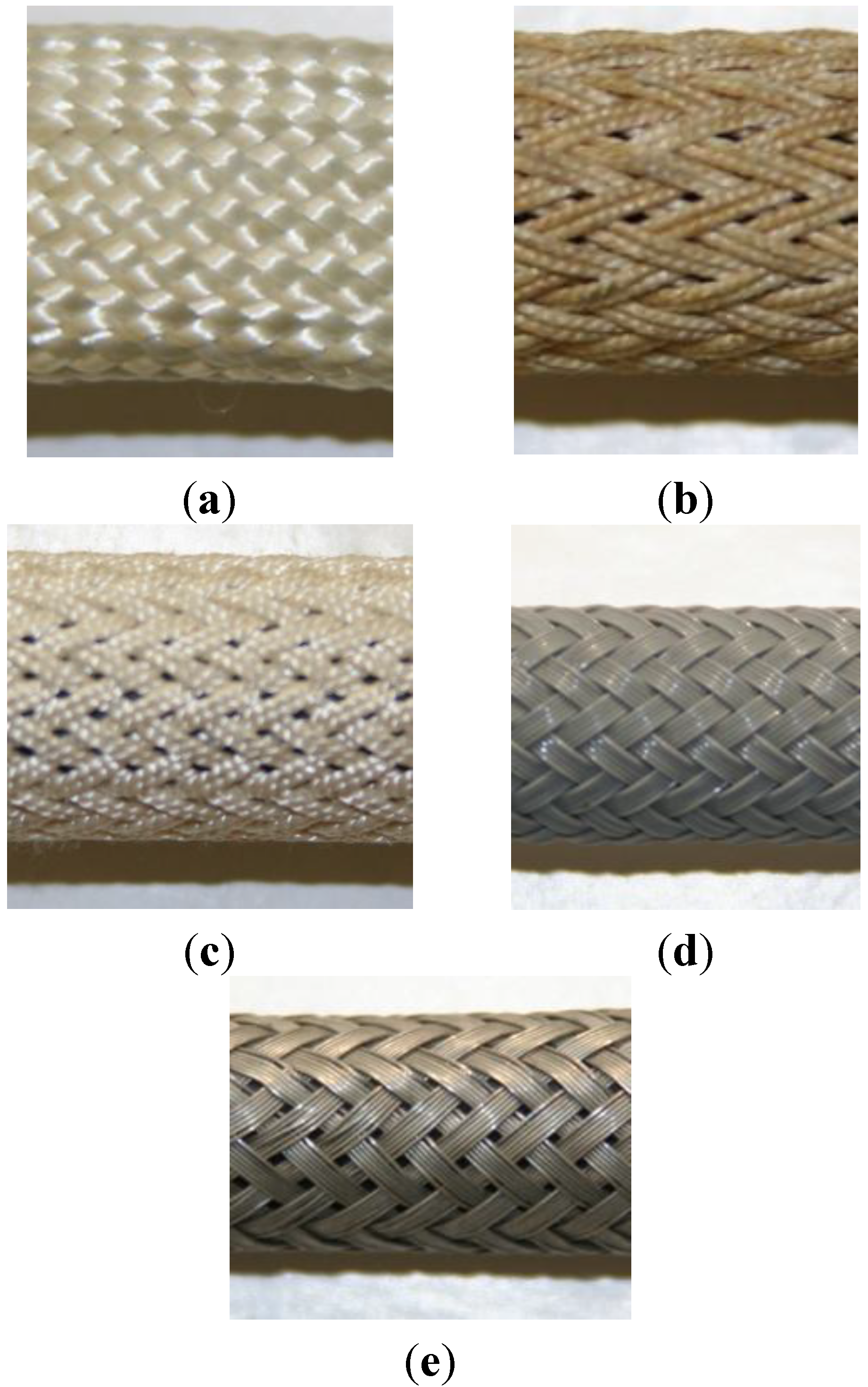
We consider three prototypes of McKibben pneumatic artificial muscle, hand-made at the laboratory, with braided sleeves made of three different materials: the first one, inspired by the historical version of the McKibben muscle, the sleeve is braided with cotton (Figure 2a) and its renewed, also textile version by Bridgestone (Figure 2b) is made of twisted rayon yarns (Figure 2c); the second one is made of thin plastic wires (Figure 2d), as this is sometimes done by McKibben muscle designers; the third one uses a material never before tested, to the best of our knowledge, for McKibben muscle design—thin metal wires (Figure 2e). These three McKibben muscles illustrate the various material possibilities for braiding McKibben muscles, from a fibrous textile material to a flexible metallic one.
Figure 2. Various braided sleeves of the pneumatic McKibben artificial muscle, (a) Historical McKibben muscle made of thin cotton yarns; (b) Bridgestone’s “rubbertuator” made of rayon yarns and (c) actual similar McKibben artificial muscle used by the authors; (d) Prototype made of braided thin plastic wires; (e) Prototype made of braided thin metal wires.
Actuators 03 00142 g002
We give in Table 1 the main estimated geometric characteristics, the estimated maximum force and maximum contraction ratio for each of the three considered prototypes. In the case of the prototype made of rayon yarns, an initial braid angle of about 23° was chosen; its initial active length—i.e., the length of the artificial muscle without its metal tips—was chosen equal to about 36 cm in order to get a maximum contraction ratio of about 10 cm in working [1–5 bar] pressure range and its initial muscle radius was specified in order that the artificial muscle generates a maximum contraction force at 5 bar close to 100 daN. But, because the two last prototypes were made with recovery materials, we were not able to select geometric parameters similar to these of the first prototype. It was, however, possible to derive benefit from industrial standardization to make two identical artificial muscles with an initial braid angle estimated to about 30° which, combined with a relatively weak initial radius, limited the maximum contraction force to about 30 daN. It is only due to a lack of materials in these preliminary experiments that we chose a length of about 32 cm for these prototypes with a plastic and metal sleeve.
Table 1. Main characteristics of the three considered McKibben artificial muscle prototypes.
Initial Length (cm)Initial Radius (mm)Initial Braid Angle (deg)Max. Force (daN) (at 5 Bar)Max. % Contraction (at 5 Bar)
Rayon yarns368231050.35
Plastic wires32630300.35
Metal wires32630300.35
We discussed in Section 1 original assumptions relative to frictional properties inside the McKibben braided sleeve. We propose in the next subsection a preliminary experimental study devoted to partially justifying these assumptions. Due to our actual limitations for testing plastic and metal-braided materials in similar conditions to these, we decided to limit this study to the rayon sleeve.

3.1. Experimental Friction Analysis of a McKibben Muscle Sleeve made of Rayon Yarns

Experimental studies in friction coefficient for fibers and yarns are generally performed with specific apparatus [
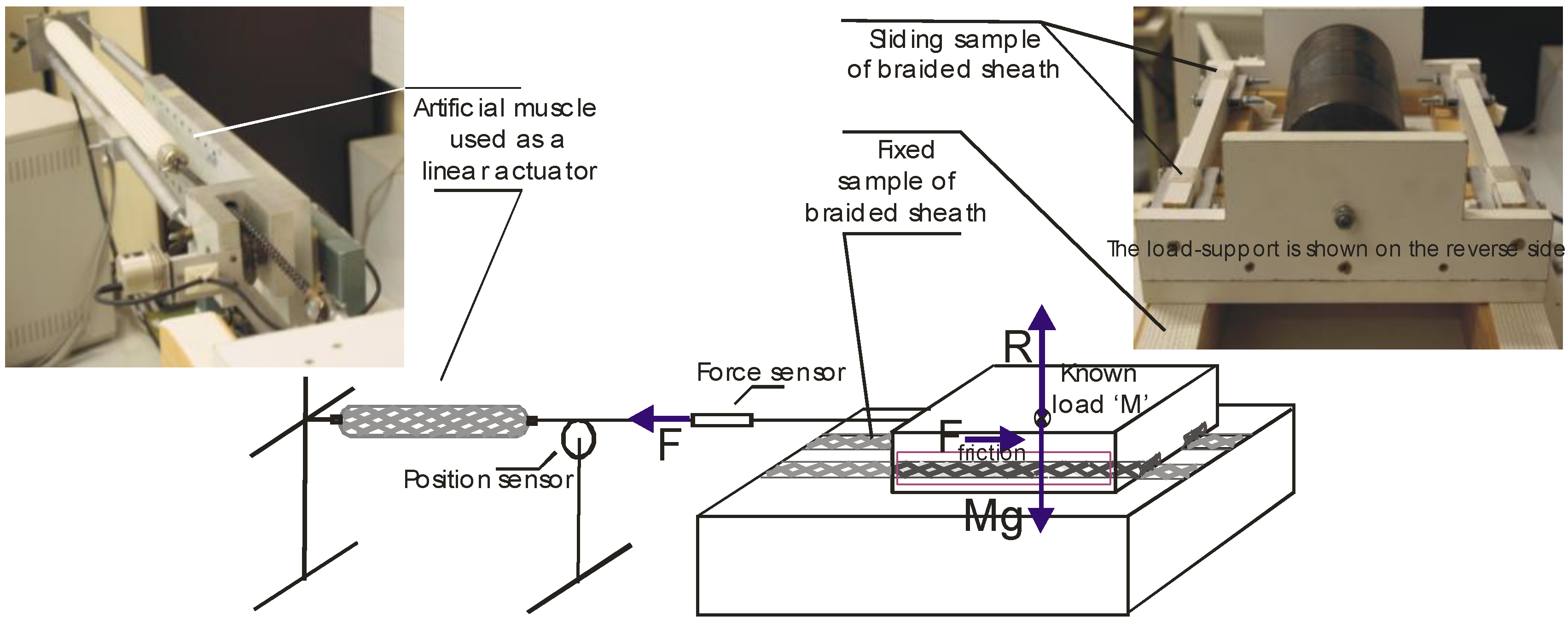
20]. We did not try to use this kind of device because our goal was not to derive the kinetic friction coefficient yarn on yarn, but to estimate the friction inside the braided sleeve during contraction of the artificial muscle. We developed the original experimental setup shown in Figure 3: a large sample of flattened braided sheath was attached to a fixed support, while a similar one was attached to a mobile support with a load of about 40 kg; an approximately 1 m long and powerful active McKibben muscle was used to drive this heavy mobile support by means of various step or constant slope input signals; current force and position were recorded during contraction.
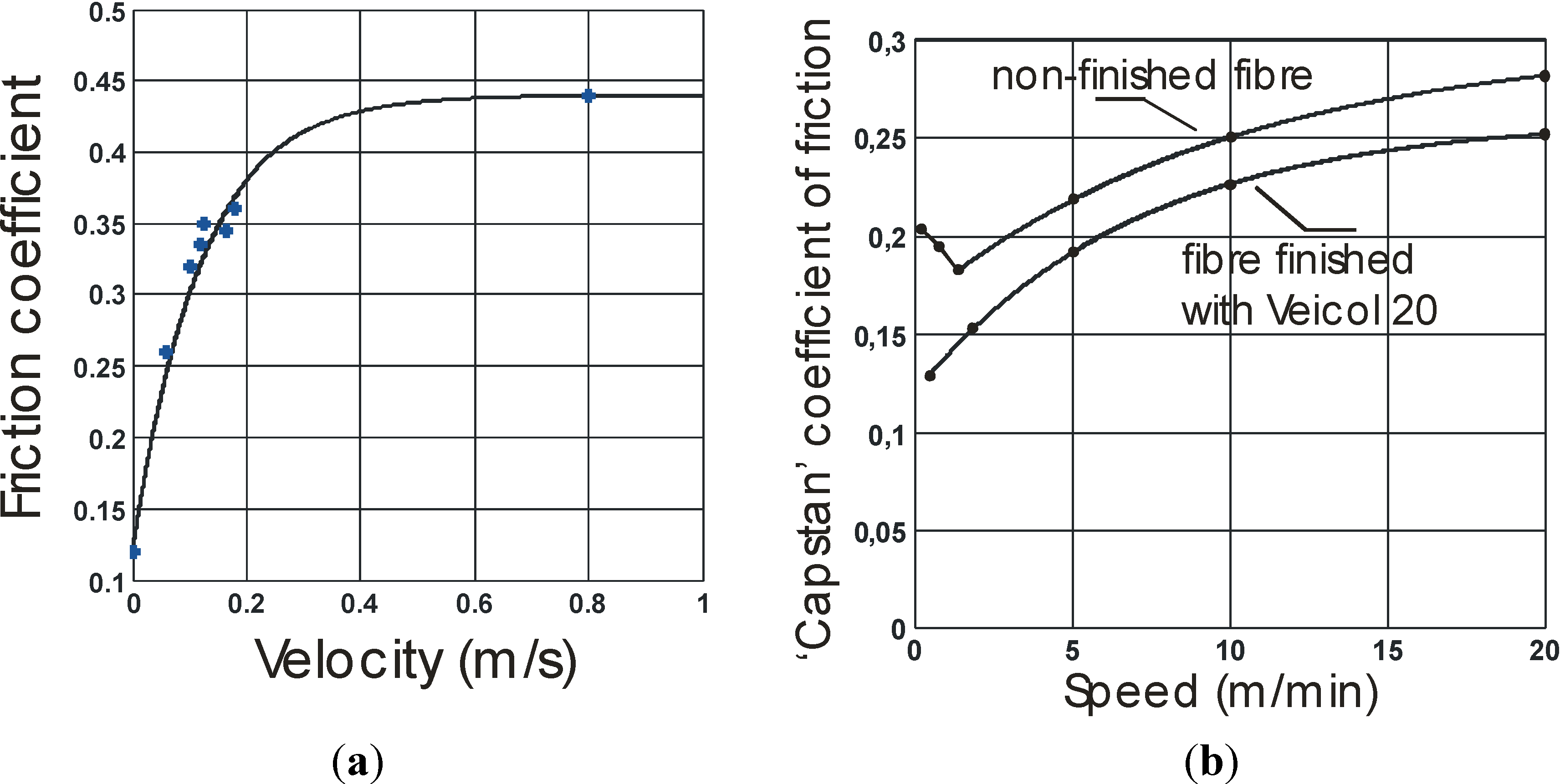
The following principle was considered: if during contraction it is possible to exhibit almost constant velocity portions, the recorded artificial muscle force is a direct estimate of the kinetic friction force corresponding to this velocity, since the inertia force is then negligible. Because the load is accurately known, the kinetic friction coefficient can be estimated for different speed values. We give in Figure 4a the set of experimental points obtained in this way and its approximation by an exponential law similar to this considered in Section 2. By comparison with a classical result from textile engineering literature, shown in Figure 4b, we get very close speed constants—the k of our theoretical model—a little higher than 0.1 m/s but different ratios of bound-kinetic friction coefficient over static one: while it is equal to about 2 in the case of Figure 4b for the sample with finishing agent, it is equal to about 3.7 in the case of our experimental curve of Figure 4a. Such a difference could be explained by the twisted character (see Figure 2c) of the selected yarns, but also by the fact that friction occurs between yarns put in different directions imposed by the double helix structure of the sheath. Moreover, and although experimental proofs are still missing, this is an interesting fact: although a ratio higher than this is generally given in classic textile engineering data, this ratio is still lower than the one we empirically considered to accurately estimate a full dynamic model of the McKibben muscle contraction: in our 2000 study [9], a similar ratio of 7 was used to be in accordance with the damped character of a prototype whose sleeve was braided with the same rayon-twisted yarns. This could suggest that the double helix structure—yarns alternatively sliding above and below their neighbors—would amplify the “textile character” of the friction phenomena inside the sleeve by increasing the ratio bound-kinetic friction coefficient over static friction coefficient. Furthermore, as previously analyzed in our paragraph devoted to stability analysis, a large value of this ratio combined with a relatively high speed constant are two stability factors for our single integral action-based closed-loop controller.
Figure 3. Experimental apparatus used to estimate the kinetic friction of a flattened sample of our rayon braided sleeve sliding over itself.
Actuators 03 00142 g003
Figure 4. Experimental estimation of the kinetic friction coefficient of our flattened rayon sheath sliding over itself (a) and comparison with a typical curve showing the kinetic friction coefficient variation for a rayon staple fiber sliding over a cylindrical array of similar fibers (redrawn from [19] with data from [21]).
Actuators 03 00142 g004

3.2. Experimental Closed-Loop Positioning Control of McKibben Artificial Muscle Contraction with a Single Integral Action

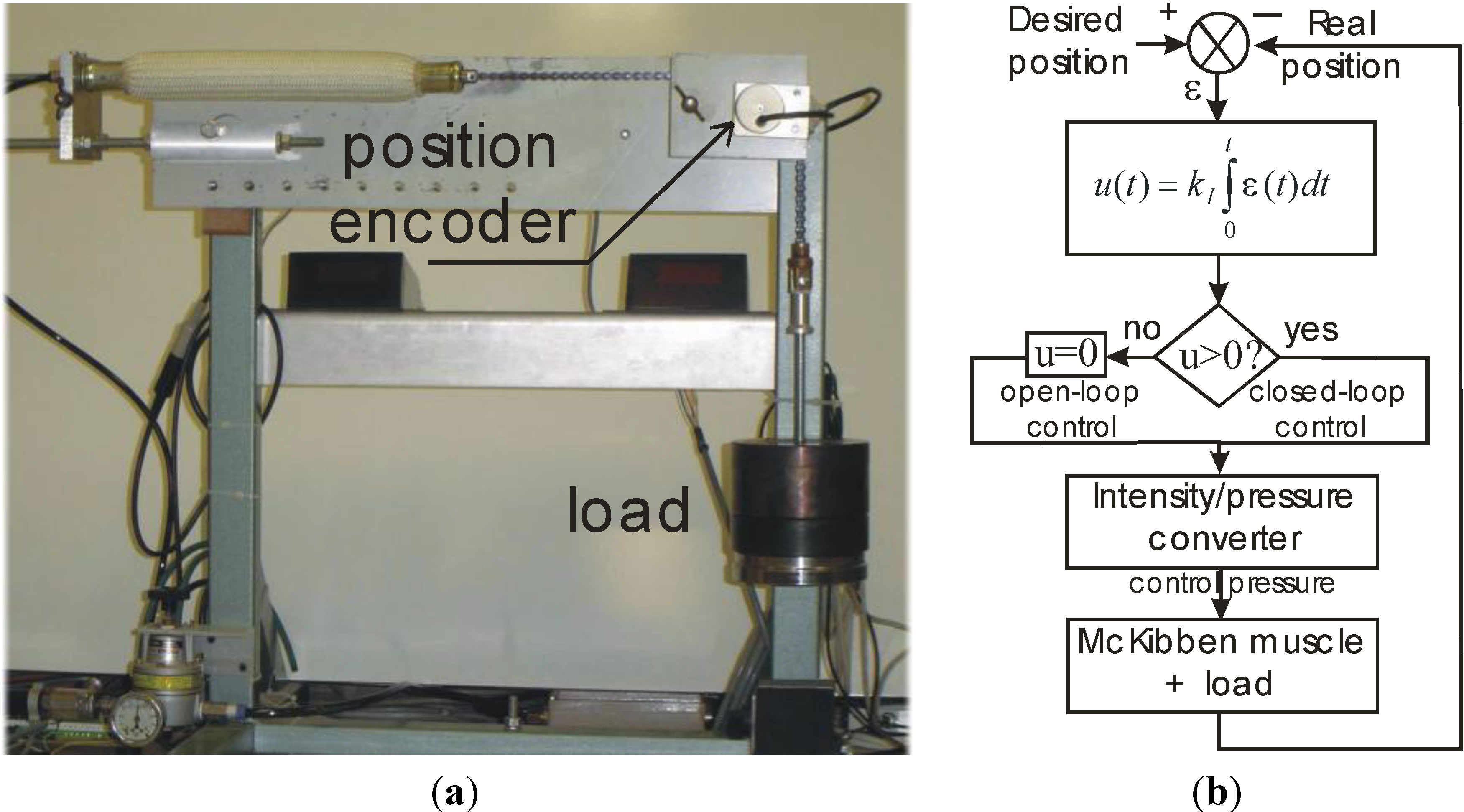
The relevance and efficiency of our proposed controller was experimentally tested on the setup shown in Figure 5a: the pressure inside the artificial muscle between 0 and 5 bar is generated by means of a Samson Intensity/Pressure converter—details about the role of this system in the McKibben muscle working and its dynamic behavior can be found in our previous study [9] and references therein—current muscle position is recorded by means of a highly accurate Heinheman optical rotation encoder; various weights can be loaded at the end of a chain driven by the artificial muscle thanks to a pulley on an axis which is fixed to the position encoder. It is important, on the one hand, to note that the real dynamic behavior of the Intensity/Pressure converter is much more complex than the simple linear first-order system considered in the simulation reported in Section 2. This is due to the fact that the artificial muscle’s internal volume to be filled at a given pressure varies during contraction; nonetheless, we trusted the I controller to make transparent for the user the nonlinear behavior of this actuator chain component. On the other hand, we must keep in mind that, in accordance with the theoretical artificial muscle model considered earlier, a fluidic McKibben muscle is a single-effect actuator with a contraction controlled by a pressure value—in a 0–5 bar range—corresponding to a positive current value of the Intensity/Pressure converter—in a 2–20 mA range—as illustrated in Figure 5b. As a consequence, a negative control value, as in the case of a negative desired position step, generates a zero control corresponding physically to an open-loop de-swelling of the artificial muscle. The closed-loop control only becomes active again beyond the lower step level, as will be illustrated in further experiments.
Figure 5. Experimental setup for testing the closed-loop positioning controller of the three considered McKibben pneumatic artificial muscles driving various loads (a) and block scheme emphasizing the single-effect character of the McKibben pneumatic artificial muscle (b)—see text.
Actuators 03 00142 g005
This is the reason why, in further reported step responses of experimental curves (see Figure 6, Figure 7 and Figure 8) our closed-loop controller—as will be the case for any other closed-loop controller—is unable to control the failing edge of the step. Only two antagonistic artificial muscles can define a double-effect actuator, but this will be not considered in the frame of this study.
Two kinds of signals were considered for testing static and dynamic accuracy of our McKibben muscle prototypes: step signals and sinus-wave signals. In both cases, the desired position is defined as an x position of the artificial muscle which must belong to the range [0, xmax], where 0 corresponds to the initial muscle state i.e., no contraction while 
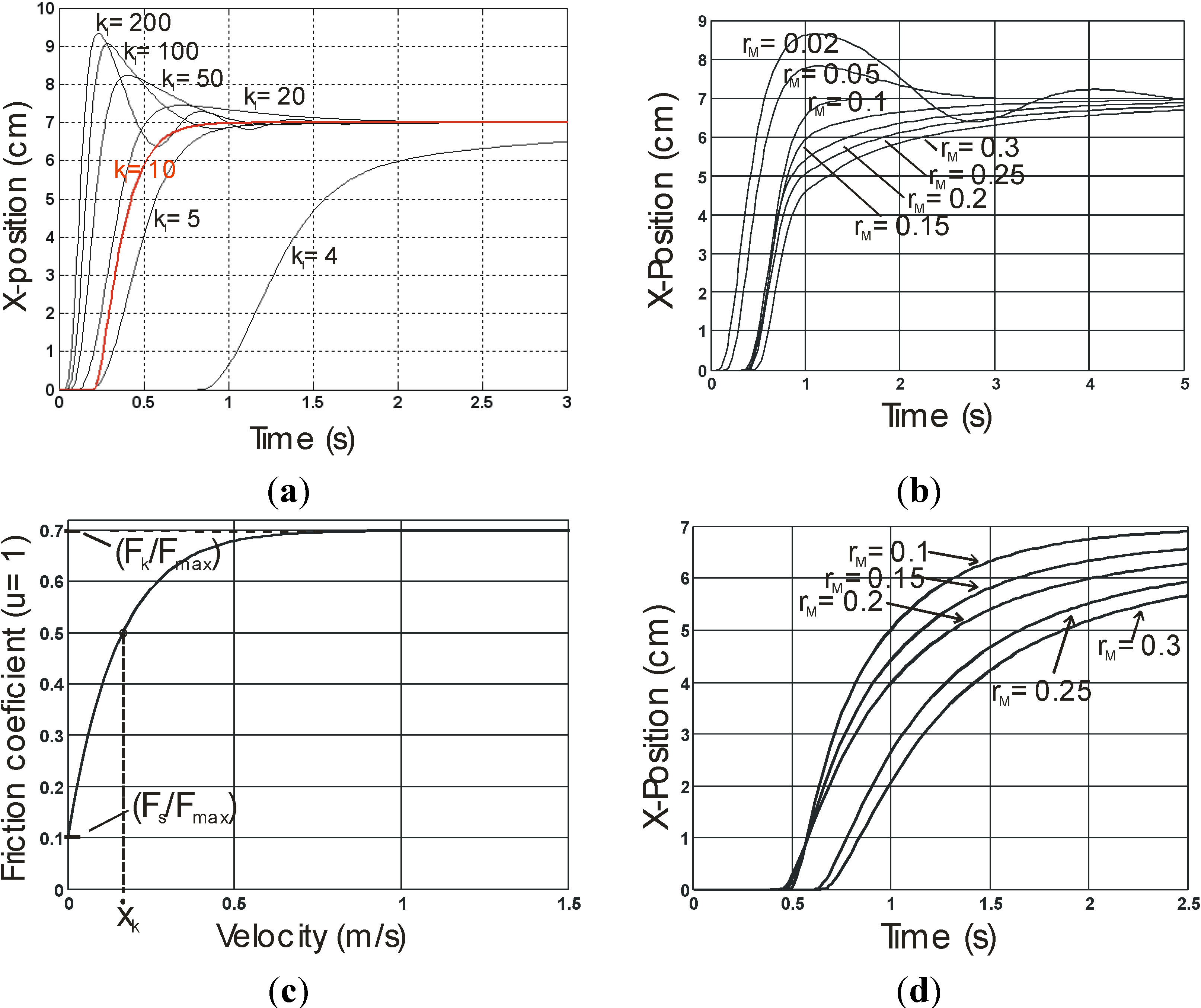
xmax corresponds to the fully contracted state of the muscle. In the case of a step signal, the desired step position was defined between a lower bound and an upper bound. Because the first prototype made of rayon yarns is relatively long and can generate a relatively high power, we decided to distinguish a “short” step with x varying from 4 to 7 cm from a “long” step with x varying from 2 to 9 cm, giving us the possibility to test load robustness with weights varying between 1 and 15 kg. It was important to test these two kinds of steps due to the nonlinear character of the artificial muscle whose dynamic behavior is not a priori independent on the step ”length.” Moreover, let us remark that with a Fmax estimated to 105 daN (see Table 1), the considered range of loads corresponds, with the notation used in section 2, to a range rM equal to about [0.01, 0.15]. In the case of the two other less powerful plastic and metal wire prototypes, we limited our analysis to a single case of a step from 1 to 5 cm making it possible to test load robustness with weights from 0.2 to 2 kg. We give in 
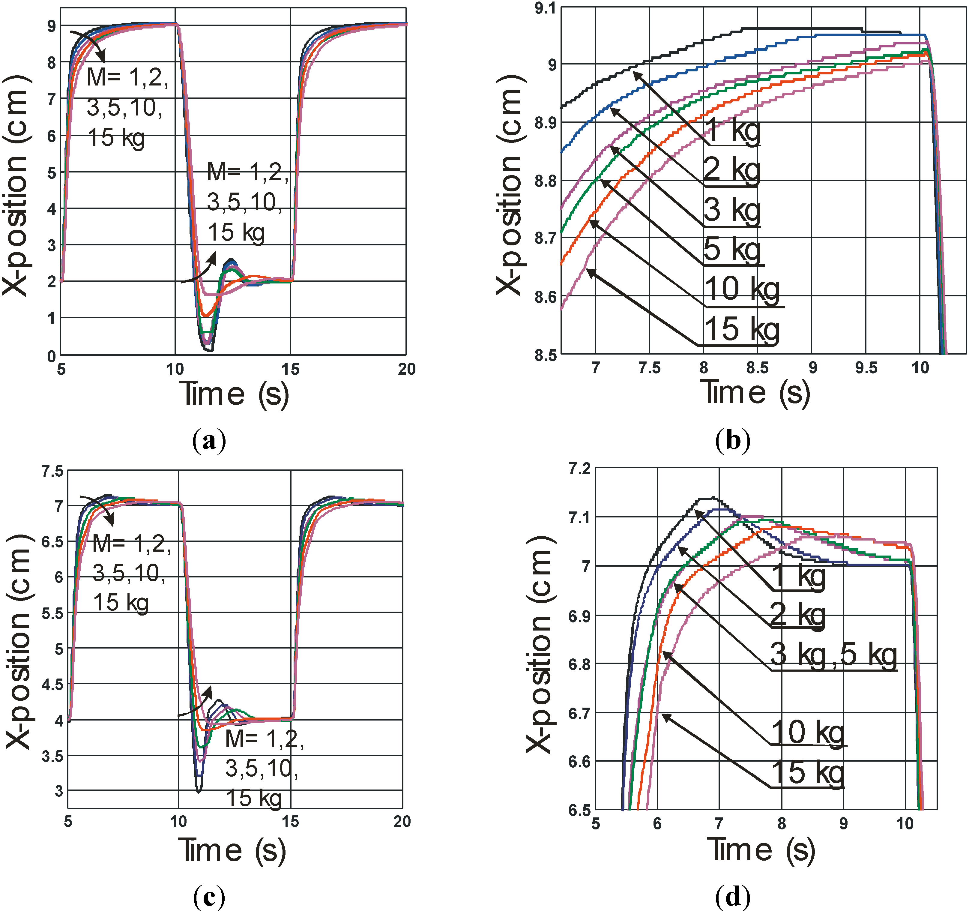
Figure 6 the experimental results obtained with our rayon McKibben muscle performing its “long” and “short” steps with a load range varying from 1 kg to 15 kg. It is worth noting that a standard kI equal to 0.0075 bar.m−1·s−1 was considered in all reported experiments. Moreover, we give in Figure 6b,d a close-up of the convergence towards the desired position in order to estimate the steady-state error when load is varying. A first point can be remarked: as predicted by our theoretical analysis, for a kI value tuned at weak load, the system’s stability is kept for any higher load, even when the controller becomes active again after the open-loop descending step phase. Moreover, in accordance with simulations, the artificial muscle contraction appears to be relatively robust to large load variations with a quasi-absence of overshooting and a response-time—estimated, for example, to 95% of the desired steady-state value—increasing from about 1 s for a weak load to about 2 s for a high load. From Figure 6b,d, a mean absolute accuracy of about 0.5 mm can be estimated, independently of load and step value. If we now consider our two other plastic (
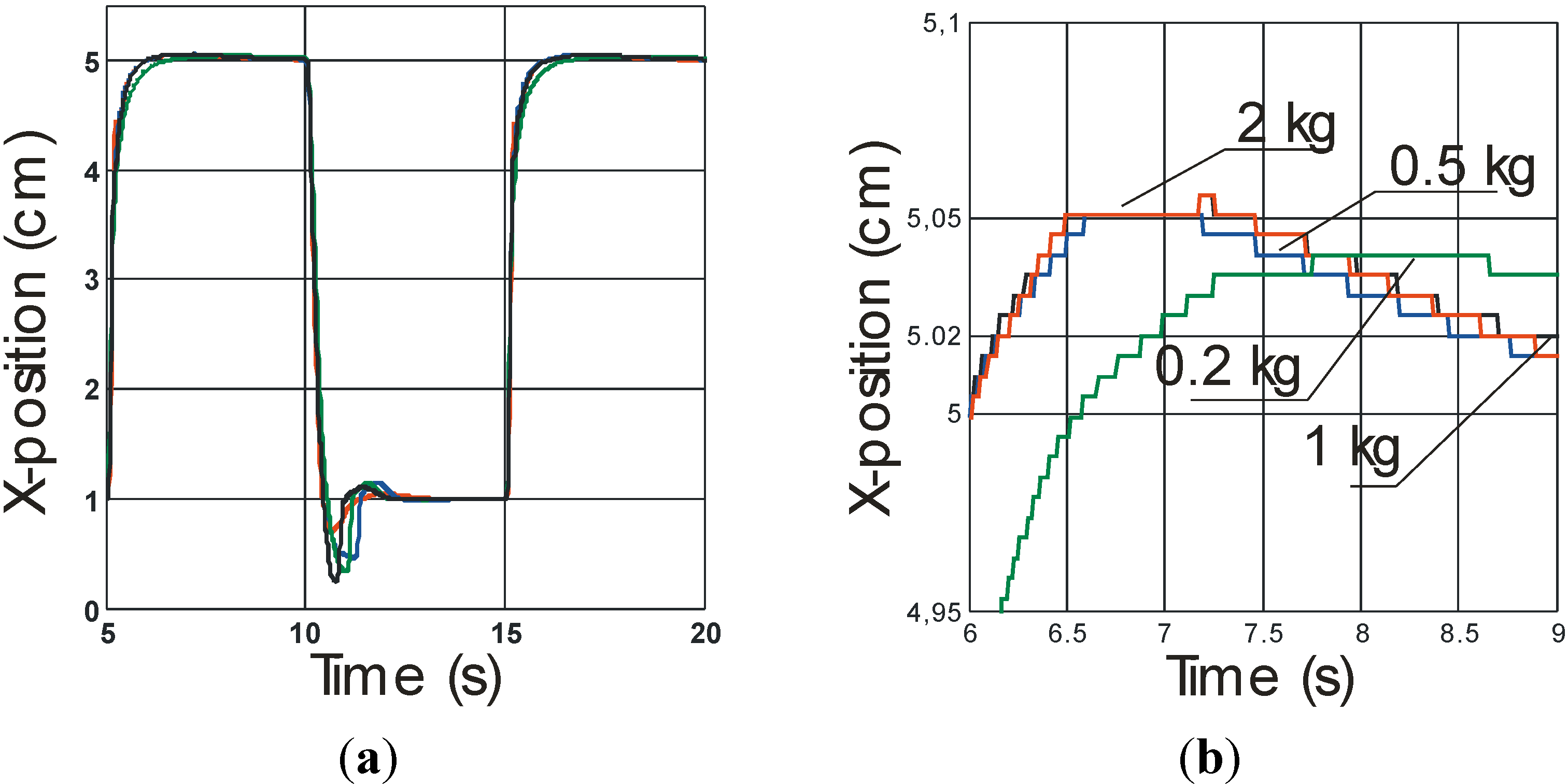
Figure 7) and metal wire (Figure 8) prototypes that we tested in the same experimental conditions of a step between 1 and 5 cm (for both artificial muscles, kI was tuned to 0.04 bar.m−1·s−1), we again highlight the load robustness with a response time of about 1 s, albeit in a tighter load range, due to the weaker artificial muscle power. However, the important point to be emphasized is the impressive accuracy obtained in the case of the artificial metal muscle: an accuracy of 1/10 mm can be read on Figure 8b.
Figure 6. Step responses performed by our rayon yarns McKibben muscle driving various loads: “long” (a)—respectively “short” (c)—step with close-up of final convergence (b)—respectively (d).
Actuators 03 00142 g006
Figure 7. Step responses performed by our plastic wire McKibben muscle driving various loads (a) and (b) Close-up of final convergence towards the desired position.
Actuators 03 00142 g007
Figure 8. Step responses performed by our metal McKibben muscle driving various loads (a) and (b) Close-up of the convergence towards the final desired position.
Actuators 03 00142 g008
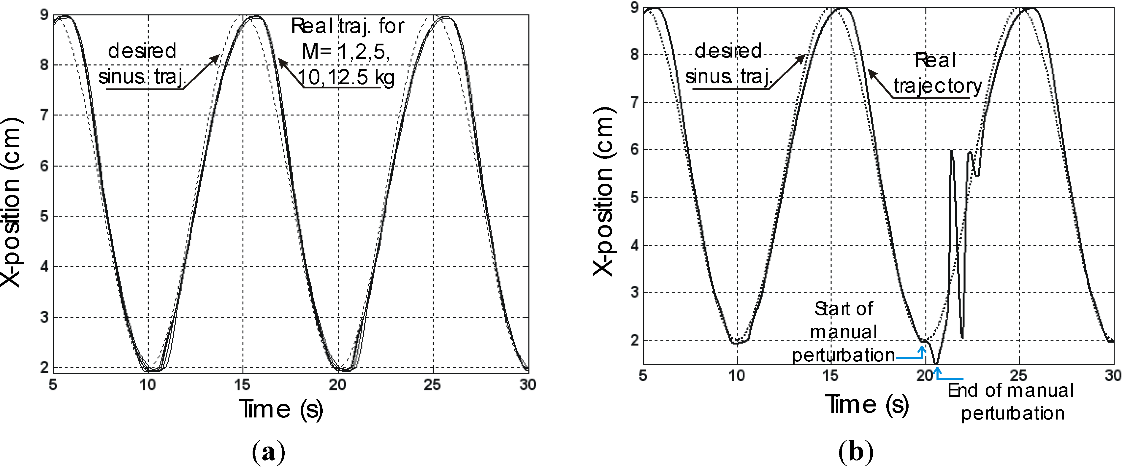
If we now consider the case of a sinus-wave tracking, with the value of kI retuned, we find again the same load robustness, particularly well illustrated in the case of our rayon yarn-braided prototype (kI was equal to 0.015 bar·m−1·s−1 for all loads), as shown in Figure 9a in the case of an imposed frequency equal to 0.1 Hz with embedded loads varying between 1 and 12.5 kg: the tracking position error appears to be independent on a load with a maximum value occurring at the change of direction, estimated to a little less than 1 cm.
Figure 9. Sinus-wave tracking at a 0.1 Hz operating frequency in the case of the rayon yarn-braided McKibben muscle (a) and (b) Effect of a manual perturbation during closed-loop control movement.
Actuators 03 00142 g009
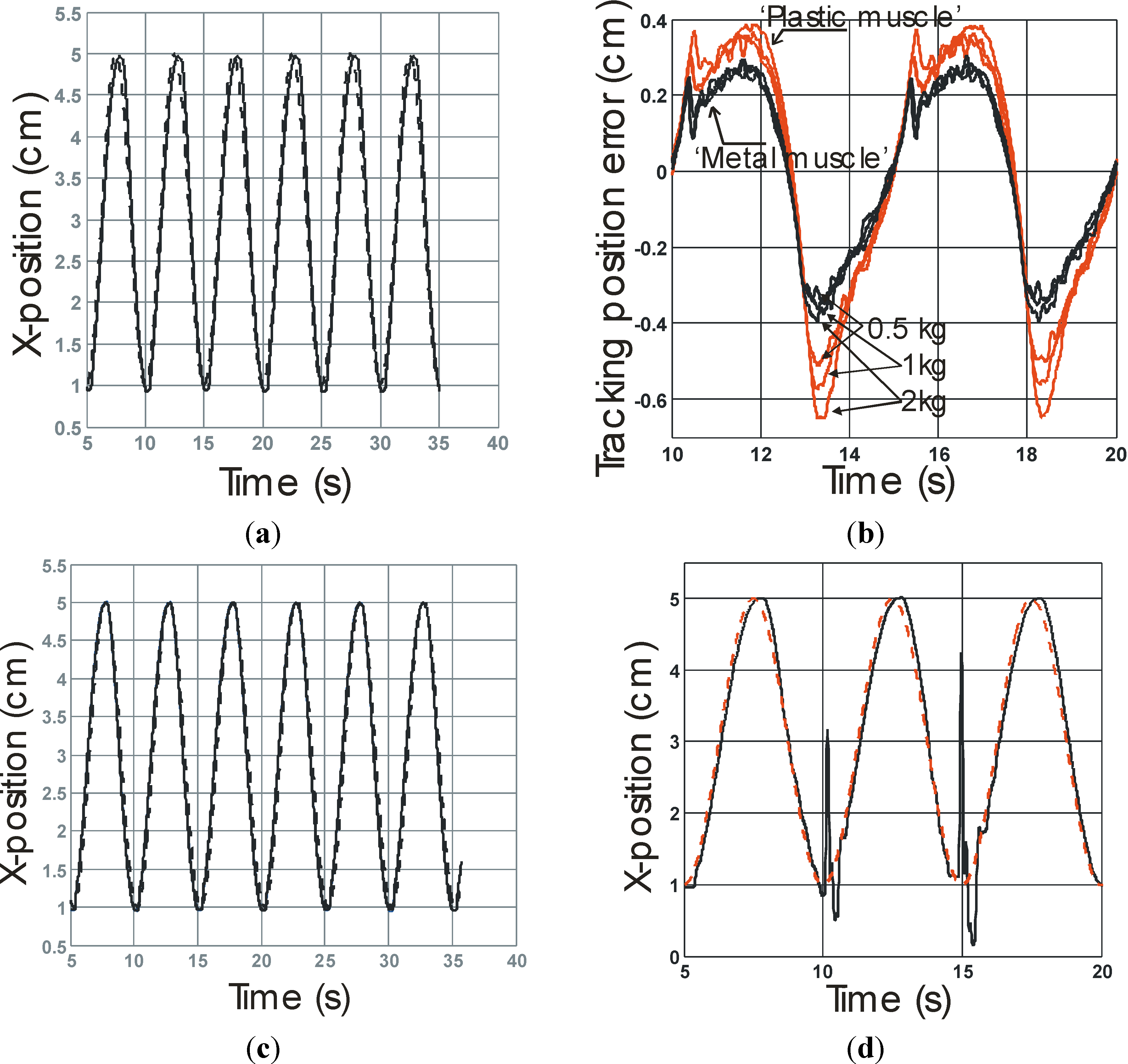
In the case of plastic and metal wire-braided prototypes, we imposed a higher frequency equal to 0.2 Hz. It is noteworthy that the range of working frequencies of a given McKibben pneumatic artificial muscle depends on the dynamic performances of the pneumatic device feeding it as on the artificial muscle volume to be filled. That is the reason why a lower frequency was used for the first muscle whose initial internal volume is about twice this of the two other prototypes. Figure 10a,c report the comparison between the desired sinus-wave and the experimental trajectory for a 1 kg load—for both “plastic” and “metal” artificial muscles, kI was tuned to 0.06 bar.m−1·s−1.
Figure 10. Sinus-wave tracking performed at a 0.2 Hz operating frequency in the case of the plastic and metal wire-braided McKibben muscle, (a) McKibben muscle made of a plastic sheath driving a 1 kg load; (b) McKibben muscle made of a metal sheath driving a 1 kgload; (c) Comparison of tracking position errors for three embedded loads equal to 500 g, 1 kg and 2 kg; (d) Effect of manual perturbations during closed-loop control movement in the case of the metal sheath McKibben muscle.
Actuators 03 00142 g010
We report in Figure 10b the tracking position error during two periods, for the two muscles driving successively three loads respectively equal to 500 g, 1 kg and 2 kg. In every case the tracking position error appears to be less to this estimated in the case of the rayon-braided muscle: it belongs to a range of [−0.7 cm, +0.4 cm] in the case of the “plastic muscle” and to a range of [−0.4 cm, +0.3 cm] in the case of the “metal muscle.” On the one hand, this result suggests that the proposed I controller is adapted to a large range of braided McKibben muscles. On the other hand, it also suggests, beyond the limitations of our study, that specific braided materials could generate weak tracking position error, as this appears to be the case in our prototype braided with thin metal wires.
We also tested the ability of the controller to reject a manual perturbation: during the sinus-wave tracking, the operator manually caught the load and released it after some seconds. It can be checked in Figure 9b and Figure 10d that the system remains stable—experiment is not reported in the case of the plastic sleeve McKibben muscle but similar results were obtained—and that the real trajectory rapidly converges again on the desired one. It is worth noting that the manual perturbation is never made in a similar way at each time and so its amplitude as its duration are not the same in reported experiments but the idea in doing that is to emphasize the compliant character of the closed-loop control particularly in response to a human interaction. It can be noted that, beyond the various considered experimental conditions, the perturbation seems better damped in the case of the rayon yarn-braided muscle than in the two other cases: this could be explained by the fact that kinetic friction and, as a consequence, damping is more pronounced in the case of this prototype in comparison with the two other considered ones.
The observed similarities in step and sinus-wave responses, as the reported differences in steady state accuracy and oscillations during perturbation rejection suggest that the three considered McKibben artificial muscles follow the same damping model with different parameters. Due to the good accordance between simulated and experimental step responses in all cases, we are led to consider that the assumed nonlinear damping model would be common to the three prototypes. This is, however, a surprising conclusion because if it is expected in the case of the sheath made of rayon yarns, it is more questionable in the non-fibrous case of plastic and metal-wire sheaths. A classic explanation given in textile technology is that the increase of kinetic friction with speed emphasizes the fundamental role of the lubrication agents during sliding. At high speeds and low loads, lubrication is partly hydrodynamic and, as written by Hansen and Tabor in their analysis of hydrodynamic factors in the friction of fibers and yarns [22]: ‘It is well known that in hydrodynamic lubrication the velocity has exactly the same effect as the viscosity of the lubricant: that is, if the velocity is increased by a factor 2, the frictional behavior is exactly the same as if the velocity had been kept constant and the viscosity has been increased by a factor 2, (assuming that no other changes have been made in the system)”. Our experimental results suggest that such hydrodynamic lubrication effect would be active in the case of a McKibben muscle sheath, whatever the material yarns or thin wires are made of. Such an assumption has to be verified by an accurate analysis of friction inside the artificial muscle braided sheath that has as of yet, to the best of our knowledge, never been undertaken. Beyond this missing understanding of friction phenomena at work during McKibben muscle contraction, a very amazing conclusion can be drawn from our experimental results: a McKibben muscle braided with thin metallic wires would give, in a closed-loop, better static and dynamic performances. Especially our prototype with our closed-loop I controller exhibits a static accuracy of about 1/10 mm, which is unexpected for a “soft actuator” associated with a very good load robustness inside the tested range.

4. Conclusions

We would like to finally highlight a double conclusion: first general a one and a then one more specifically devoted to McKibben artificial muscle technology. In a general way, we considered in this paper any rectilinear artificial muscle as being an original actuator characterized by its own stiffness proportional to control variable and an associated damping component which gives to the artificial muscle its open-loop stability. As a consequence, we suggested that a simple I controller would be relevant to control its positioning in closed-loop instead of the classic PID, with the following advantages: (1) there is no need for a dynamic model of the artificial muscle to look for high static and dynamic accuracies which are often problematic in soft actuator control; and (2) there is only a single parameter to tune which can eventually be adapted to tasks with specific compliance requirements. Although our stability analysis has to be improved, it appeared in good accordance with our experimental results. We believe that this I controller could be efficiently applied to a large class of artificial muscles if a damping component, whatever its nature, exists.
Our I controller has proved to be particularly efficient in the case of the tested pneumatic McKibben muscles. During our experiments made with three prototypes respectively braided with rayon yarns, plastic wires and metal wires, a surprising result occurred: by using thin metal wires, a static accuracy of about 1/10 mm was obtained without losing load robustness and stable perturbation rejection. Good tracking performance is also obtained with this prototype. Further experiments in friction will try to better analyze how a non-fibrous material used to braid a typical McKibben muscle sheath can behave like a textile material with damping performances apparently well more adapted to an accurate, quick and robust closed-loop control.
The simulation as experimental reported results are, however, limited to a closed-loop control of the artificial muscle contraction. A further step would be to apply this approach to a pair of antagonistic artificial muscles in order to check if similar accuracy and load robustness performances can be obtained with a “double effect”—positive and negative rotation—artificial muscle actuator.

Acknowledgments

I thank sincerely the three reviewers for their very pertinent remarks that helped this article become clearer and more precise.

Conflicts of Interest

The author declare no conflict of interest.

References

  1. Hesselroth, T.; Sarkar, P.; van der Smagt, P.; Schulten, K. Neural Network Control of a Pneumatic Robot Arm. IEEE Trans. Syst. Man Cybern. 1994, 24, 28–37. [Google Scholar] [CrossRef]
  2. Tian, S.; Ding, G.; Yan, D.; Lin, L.; Shi, M. Nonlinear Controlling of Artificial Muscle System with Neural Networks. In Proceedings of the 2004 IEEE International Conference on Robotics and Biomimetics, Shengyang, China, 22–26 August 2004; pp. 56–59.
  3. Thanh, TU.D.C.; Ahn, K.K. Nonlinear PID Control to Improve the Control Performance of 2 Axes Pneumatic Artificial Muscle manipulator Using Neural Network. Mechatronics 2006, 16, 577–587. [Google Scholar] [CrossRef]
  4. Thongchai, S.; Goldfarb, M.; Sarkar, N.; Kawamura, K. A Frequency Modeling Method of Rubbertuators for Control Application in an IMA Framework. In Proceedings of the 2001 Conference on American Control, Arlington, VA, USA, 25–27 June 2001.
  5. Ahn, H.P.H.; Ahn, K.K. Hybrid Control of a Pneumatic Artificial Muscle (PAM) Using an Inverse NARX Fuzzy Model. Eng. Appl. Artif. Intell. 2011, 24, 697–776. [Google Scholar] [CrossRef]
  6. Caldwell, D.G.; Medrano-Cerda, G.A.; Goodwin, M. Control of Pneumatic Muscle Actuators. IEEE Control Syst. Mag. 1995, 15, 40–48. [Google Scholar] [CrossRef]
  7. Zhu, X.; Tao, G.; Yao, B.; Cao, J. Adaptive Robust Posture Control of a Parallel Manipulator Driven by Pneumatic Muscles. Automatica 2008, 44, 2248–2257. [Google Scholar] [CrossRef]
  8. Cai, D.; Dai, Y. A sliding Mode Controller for Manipulator Driven by Artificial Muscle Actuators. Electron. Commun. Jpn. 2003, 86, 57–64. [Google Scholar]
  9. Tondu, B.; Lopez, P. Modeling and Control of McKibben Artificial Muscle Robot Actuators. IEEE Control Syst. Mag. 2000, 20, 15–38. [Google Scholar] [CrossRef]
  10. Braikia, K.; Chettouh, M.; Tondu, B.; Acco, P.; Hamerlain, M. Improved Control Strategy of 2-Sliding Controls Applied to a Flexible Robot Arm. Adv. Robot. 2011, 25, 1515–1538. [Google Scholar] [CrossRef]
  11. Jouppila, V.T.; Gadsden, S.A.; Bone, G.M.; Ellman, A.U.; Habibi, S.R. Sliding Mode Control of a Pneumatic Muscle Actuator System with a PWM Strategy. Int. J. Fluid Power 2014, 15, 19–31. [Google Scholar] [CrossRef]
  12. Minh, T.V.; Tjahjowidodo, T.; Ramon, H.; van Brussel, H. Control of Pneumatic Artificial Muscle (PAM) with Model-based Hysteresis Compensation. In Proceedings of the IEEE/Adv. International Conference on Mechatronics, Singapore, 14–17 July 2009; pp. 1082–1087.
  13. Xiangrong, S. Nonlinear Model-based Control of Pneumatic Artificial Servo Systems. Control Eng. Practice 2010, 18, 311–317. [Google Scholar] [CrossRef]
  14. Woods, B.K.S.; Choi, Y.T.; Kothera, C.S.; Wereley, N.M. Control System Development for Pneumatic Artificial Muscle-Driven Active Rotor Systems. AIAA J. Guidance Control Dyn. 2013, 36, 1177–1185. [Google Scholar] [CrossRef]
  15. Tondu, B. Closed-Loop Position Control of Artificial Muscles with a Single Integral Action. In Proceedings of the IEEE International Conference on Mechatronics (ICM-2013), Vicence, Italy, 27 February 2013–1 March 2013.
  16. Hogan, N. Adaptive Control of Mechanical Impedance by Coactivation of Antagonist Muscles. IEEE Trans. Autom. Control 1984, AC-29, 681–689. [Google Scholar] [CrossRef]
  17. Tondu, B. Modelling of the McKibben Artificial Muscle: A Review. J. Intell. Mater. Syst. Struct. 2012, 23, 225–253. [Google Scholar] [CrossRef]
  18. Davis, S.; Caldwell, D.G. Braid Effects on Contractile Range and Friction Modeling in Pneumatic Muscle Actuators. Int. J. Robot. Res. 2006, 25, 359–360. [Google Scholar] [CrossRef]
  19. Tabor, D. Chap. 3 Mechanism of Lubrification. In Friction in Textiles; Butterworths Scientific Publications: London, UK, 1959; pp. 54–76. [Google Scholar]
  20. Mieszkis, K.W. Chap. 10 Measurement of Friction of Yarns and Fibres. In Friction in Textiles; Butterworths Scientific Publications: London, UK, 1959; pp. 165–207. [Google Scholar]
  21. Röder, H.L. Measurements of the Influence of Finishing Agents on the Friction of Fibres. J. Text. Inst. 1953, 44, T247–T265. [Google Scholar] [CrossRef]
  22. Hansen, W.V.; Tabor, D. Hydrodynamic Factors in the Friction of Fibers and Yarns. Text. Res. J. 1957, 27, 300–306. [Google Scholar]

