Article

Control of a Heavy-Lift Robotic Manipulator with Pneumatic Artificial Muscles

by
Ryan M. Robinson
1,
Curt S. Kothera
2 and
Norman M. Wereley
1,*
1
Department of Aerospace Engineering, University of Maryland, College Park, MD 20742, USA
2
InnoVital Systems Inc., Beltsville, MD 20705, USA
*
Author to whom correspondence should be addressed.
Actuators 2014, 3(2), 41-65; https://doi.org/10.3390/act3020041
Submission received: 4 November 2013 / Revised: 5 April 2014 / Accepted: 10 April 2014 / Published: 24 April 2014
(This article belongs to the Special Issue Soft Actuators)

Abstract

:
Lightweight, compliant actuators are particularly desirable in robotic systems intended for interaction with humans. Pneumatic artificial muscles (PAMs) exhibit these characteristics and are capable of higher specific work than comparably-sized hydraulic actuators and electric motors. The objective of this work is to develop a control algorithm that can smoothly and accurately track the desired motions of a manipulator actuated by pneumatic artificial muscles. The manipulator is intended for lifting humans in nursing assistance or casualty extraction scenarios; hence, the control strategy must be capable of responding to large variations in payload over a large range of motion. The present work first investigates the feasibility of two output feedback controllers (proportional-integral-derivative and fuzzy logic), but due to the limitations of pure output feedback control, a model-based feedforward controller is developed and combined with output feedback to achieve improved closed-loop performance. The model upon which the controller is based incorporates the internal airflow dynamics, the physical parameters of the pneumatic muscles and the manipulator dynamics. Simulations were performed in order to validate the control algorithms, guide controller design and predict optimal gains. Using real-time interface software and hardware, the controllers were implemented and experimentally tested on the manipulator, demonstrating the improved capability.

Graphical Abstract

1. Introduction

Commercial and domestic applications for mobile robots continue to expand into areas that require human-robot interaction. Often, the design objectives considered in mobile robotic applications are low weight, high range of motion, high torque and low power. However, interaction with humans warrants additional safety measures, including compliant manipulation. This requirement is problematic for many conventional actuators, which typically use high stiffness to achieve high performance, thereby increasing inertia and leading to large impact forces upon collision [1].
One type of actuator that can satisfy these competing requirements is the pneumatic artificial muscle (PAM). PAMs are extremely lightweight, compliant and capable of higher specific work than comparably-sized hydraulic actuators and electric motors [2]. They are typically composed of a helically braided sleeve surrounding an elastomeric bladder and are held together by end fittings. Pressurization of the soft bladder inflates the muscle and causes the stiff braid fibers to reorient, generating a contractile stroke and pulling force similar to human muscle. Also known as McKibben actuators, PAMs were initially developed as orthotic devices for polio patients [3]. Similar applications have dominated the field over the years, with PAM-powered devices for orthotics and rehabilitation [4,5,6] and biologically-inspired humanoid robotic devices [7,8]. Looking to other applications, these actuators are particularly desirable in portable robotic systems intended for interaction with humans [1], such as those envisioned for nursing assistance and in casualty extraction. Similar designs with bi-directional capabilities [9] may permit an even greater range of applications.
While being considered in robotics for several decades, work still remains to develop an all-encompassing PAM model formulation. Many modeling approaches exist, including energy balance [10], force balance [11] and finite elasticity theory [12], but precise modeling of the nonlinear behavior has proven difficult. Moreover, scalability to different sizes, length-to-diameter ratios and bladder thickness-to-diameter ratios have seen limited success. Direction-dependent hysteresis, caused by the interaction between the bladder and braid, can be approximated using the empirical Preisach model [13] or by modeling braid-bladder and inter-braid contact [14], but hysteresis is difficult to predict a priori for different materials and geometries. Modeling error is compounded farther in PAM systems when considerations for the flow and compressibility of air are included, making precise control difficult. Control is especially difficult for a PAM-based manipulator, with payload weights ranging from zero to several times the mass of the manipulator itself.
Past efforts to control pneumatic artificial muscles span a wide range of established techniques. Caldwell et al. [15] used adaptive control based on model estimation, demonstrating accuracy for lightweight payloads (0.325 kg (0.7 lb)) over 9 deg of arm rotation. However, it is important that manipulators intended to lift humans can handle payloads exceeding their own weight and can operate over a much larger range of motion. Ahn and Nguyen [16] developed an intelligent switching algorithm using a learning vector quantization neural network for various payloads, showing experimental data for step inputs. This controller requires “training” the neural network for an extended amount of time before the system could reliably lift different payloads. Wu et al. [17] developed a self-tuning fuzzy proportional-integral-derivative (PID) controller for a hand exoskeleton actuated by PAMs. The experiments showed undesired oscillation about the reference trajectory, though there was a time-varying disturbance, due to human input. Yeh et al. [18] designed an optimal controller using loop transfer recovery (LTR) for a leg exoskeleton, which was deemed successful, but limited to only 15 deg of rotation. Beyl et al. [19] developed a PAM-actuated gait rehabilitation robot, which demonstrated good performance and allowed for knee flexion angles of up to 90 deg.
When manipulator joint trajectories require high speed and acceleration, the tracking capabilities of pure feedback control are degraded [20]. Moreover, over-simplified computed torque controllers or adaptive controllers with slow parameter updating may not have the capability to track fast nonlinear dynamics. To address this problem, several approaches to PAM-based control have incorporated highly detailed models of the system. Zhu et al. [21] designed an adaptive robust controller for a parallel manipulator with only a few degrees of movement, incorporating a model of the flow dynamics and valve. Ganguly et al. [22] introduced static and dynamic empirical models of PAM actuation and valve characteristics in a model-based PID controller for a rotary joint. The adoption of feedforward compensation was shown to improve system response in the work by Nho and Meckl [23], who demonstrated neuro-fuzzy and inverse dynamics feedforward control on a two-link manipulator. Fateh and Izadbakhsh [24] employed a hybrid computed torque approach to a two-link manipulator and found that feedforward control reduces tracking error. These model-based feedforward strategies influenced the design of the control system in the present study.
Control studies on PAM-based systems have often employed sliding mode control, a robust nonlinear control strategy, which drives the dynamics of the system to that of an exponentially stable system [25]. This methodology has been extended to adaptively control robot manipulators [26], improving the response to unmodeled dynamics or payload variations. Many sliding control algorithms have been proven to be globally stable when model errors and system disturbances are bounded [27]. Carbonell et al. [28], Cai and Dai [29] and Lilly [30] performed simulations of PAM-actuated systems using sliding mode controllers. However, these second-order controllers assume that the PAM pressure or force being used as a control input is instantaneous, which cannot be assumed in a practical system with a large PAM volume. Similarly, Nouri et al. [31] designed an adaptive controller with a sliding component, which neglected airflow dynamics for lightweight payloads (0.6 kg (1.3 lb)). Xing et al. [32] applied sliding mode control with a disturbance observer to a PAM in linear motion experiments with a 1-kg (2 lb) load. While the controller showed good performance, airflow dynamics were neglected, and the commanded pressure was assumed to be instantaneous, which is not realistic in more demanding applications. In order to address such problems, Shen [33] designed a model-based sliding mode controller, including a dynamic airflow model, and applied it to a linear table actuated by PAMs. Aschemann and Schindele [34] developed a cascaded sliding mode controller for a high-speed linear axis with a detailed empirical model of valve dynamics for pressure feedback and a model of the linear axis for position feedback. As in other model-based control strategies, these detailed physical models were necessary to achieve satisfactory performance. Tondu et al. [35] applied sliding mode control with twisting and super-twisting algorithms to two degrees-of-freedom of a PAM-based manipulator, noting that the equivalent force control term was not helpful on the link farther from the base because of model uncertainty. Overall, studies that have successfully applied sliding mode control to experimental PAM-actuated systems have used systems with high stiffness, low inertial loads and minimal time delays. However, the robotic arm in the present study, as outlined in the following section, exhibits relatively low stiffness, highly variable inertial loads and substantial time delay. Moreover, sliding mode control can be negatively affected by measurement noise and low-resolution sensors, which are present in the system. The authors intend to investigate the implementation of an adaptive sliding mode controller on a system better suited to this strategy in future work.
While many of these studies have demonstrated smooth and accurate motion, control of a PAM-actuated manipulator with both a high range of motion (90 deg) and high tip payload variations (0 to 45 kg (0 to 100 lb)) has not been attempted. It should be noted that the manipulator arm in question weighs 7 kg (15 lb), several times less than the maximum payload. In previous work, the authors detailed the design and construction of the proof-of-concept manipulator actuated by pneumatic artificial muscles that was intended for interaction with humans [36]. The objective of the present work is to develop a control algorithm for this manipulator that satisfies accuracy and smooth motion requirements. This began first by considering proportional-integral-derivative (PID) and fuzzy logic controllers, but moved toward a model-based feedforward structure to achieve improved performance. In this study, the controllers were simulated and experimentally tested on the manipulator. System performance was evaluated for different trajectories and payloads. Additionally, the effect of varying the gain in the feedforward model was analyzed.

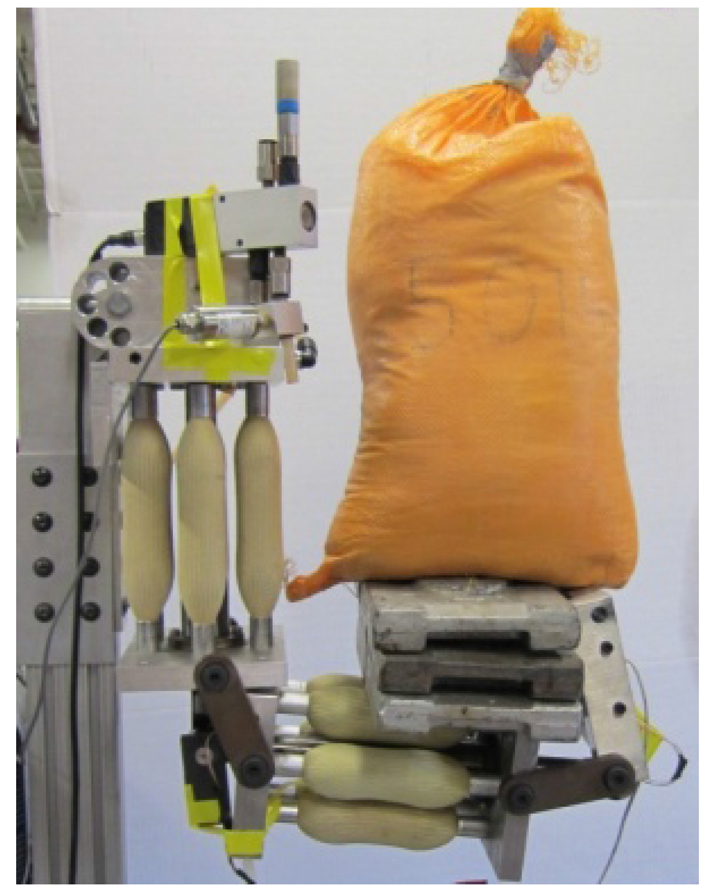
2. PAM-Actuated Robotic Manipulator

2.1. Design and Experimental Setup

The PAM-actuated manipulator was designed and constructed in a previous study [36]. Figure 1 illustrates the components of the actuator system, including a high-pressure air source, pneumatic valves and a manipulator. As illustrated, the actuators provide torque in only the positive direction, and gravity provides a restoring force in the opposing direction. In other words, the system is not operating in an antagonistic configuration. While an antagonistic PAM configuration would allow variable stiffness control [37], the goal of this study was position control; therefore, a unidirectional actuation system was deemed sufficient. The manipulator design includes space for a compression spring to provide antagonistic force; however, a spring was not used in this study. An earlier design study determined that several parallel actuators generated higher specific force and force density than a single large actuator [36]. Figure 2 shows the arm in operation, holding 50 kg (110 lb). Throughout experimentation, angular Hall-effect sensors (Midori Precisions) were attached to each joint to measure rotation angles, which typically varied from 0 to 100 deg. Pressure transducers (Omegadyne Inc.) were attached to incoming air lines to monitor PAM pressure. Each degree-of-freedom can be fed compressed air through a proportional servo-valve (Festo MYPE-type). However, in these experiments, only the elbow joint was actuated. The cross-sectional area of the valve inlet and outlet are a function of the voltage sent from the controller. Hence, the controller was capable of directly manipulating the flow rate of air.
Figure 1. Schematic of the pneumatic artificial muscle (PAM)-actuated manipulator system.
Actuators 03 00041 g001
Figure 2. PAM-actuated joint holding 50 kg (110 lb).
Actuators 03 00041 g002
The sensors and control valves were connected to a dSPACE® real-time interface, which allowed for quick implementation and modification of controllers modeled in Simulink®. In these single degree-of-freedom (SDOF) control experiments, a single-input, single-output (SISO) controller was employed for elbow rotation. Output error between the measured (actual) angle and the reference (desired) angle was used to compute a voltage to the control valve. The pressure supply was set to 0.83 MPa (120 psi).

2.2. System Model

A complete model of the elbow degree-of-freedom consists of three major components: the airflow through the valve, the response of the PAM actuators and the manipulator dynamics. The control valve regulates air pressure in the actuators, which is used to calculate the PAM force. PAM force is then translated to actuator motion. Airflow is regulated by the control voltage to the valve, whose orifice area, A, is a nonlinear function of the control voltage. The orifice area is calculated by interpolating values from a lookup table.
The mass flow rate of air depends on both upstream and downstream pressures, P u s and P d s , and the orifice area:
m ˙ a i r = A C d P u s 2 R T C 1 , P d s P u s < P c r A C d P u s 2 R T C 2 , P d s P u s P c r
The term, C d , is a discharge coefficient capturing the losses in the orifice; P c r = ( 2 / ( γ + 1 ) ) γ / ( γ 1 ) is the critical pressure separating subsonic and supersonic flow, and C 1 and C 2 are given by:
C 1 = γ γ 1 P d s P u s 2 γ P d s P u s γ 1 γ C 2 = 2 γ + 1 1 γ 1 γ γ + 1
where γ is the specific heat ratio of air.
Richer and Hurmuzlu [38] derived an expression for pressure change in a container of changing volume using the ideal gas law, conservation of mass and conservation of energy:
P ˙ = R T V a i r ( α i n m i n α o u t m o u t ) α P V ˙ a i r V a i r
where R is the specific gas constant for air, T is air temperature, V a i r is air volume in the PAMs, α i n = 1 . 4 and α o u t = 1 are the respective specific heat ratios of the gas flow into and out of the PAMs and α = 1 . 2 is the approximate specific heat ratio due to volume change. From this expression of pressure rate, the time-varying pressure inside the PAM actuators can be determined by integration.
Quasi-static PAM actuator models relating force to contracted length and applied pressure can be derived using a number of approaches [39]. Experimental data was found to best match the force balancing method derived initially by Ferraresi et al. [11]. In this model, corrected for the effect of non-constant bladder thickness, PAM force is given by:
F = P 4 π N 2 3 ( L 0 Δ L ) 2 B 2 + P V B L 0 Δ L ( t 0 Δ t ) ( L 0 Δ L ) 2 π ( R 0 Δ R ) 2 N 2 + F L + F T
where L 0 is resting length, Δ L is contraction, V B is bladder volume, B is braid length, N is the number of braid turns around the circumference of the PAM, t 0 is the resting bladder thickness, Δ t is the change in bladder thickness, R 0 is the resting bladder radius and Δ R is the change in radius. The forces, F L and F T , are pressure-independent terms governed by the elasticity of the bladder, E R , and are as follows:
F L = E R V B 1 L 0 1 L 0 Δ L
F T = E R ( L 0 Δ L ) 2 π ( R 0 Δ R ) N 2 [ ( t 0 Δ t ) ( L 0 Δ L ) t 0 L 0 ]
This formulation was found to be accurate for PAMs undergoing contraction, but there is an inherent hysteresis that alters the force-contraction profile in extension. In extension, the resistive force preventing the PAM bladder from expanding increases the PAM force. Furthermore, there is friction both between the braid and bladder and between the braid fibers themselves. This hysteresis is captured in the model by adding empirical constants to the terms:
F 2 = P 4 π N 2 3 ( L 0 Δ L ) 2 B 2 + 0 . 3 P V B L 0 Δ L ( t 0 Δ t ) ( L 0 Δ L ) 2 π ( R 0 Δ R ) 2 N 2 + 0 . 8 F L + 0 . 8 F T
Force from the PAM group is translated into an arm torque, defined as τ = F r e f f cos θ f n P A M , where r e f f is the effective length of the moment arm (nonlinear function of joint angle), θ f is the angle between the stationary upper link and the joint tendon and n P A M is the number of parallel PAMs in the muscle group.
PAM torque is resisted by the weight and inertia of the arm and payload. The arm dynamics for single degree-of-freedom motion are related to PAM torque by:
τ = I z θ d ¨ + m p l d l a r m 2 θ d ¨ + ( m a r m l c , a r m + m p l d l a r m ) g sin θ d
where θ d is the desired angle, I z is the link inertia, m a r m is the arm mass, l c , a r m is the distance between the joint and the link center of mass, m p l d is the payload mass, l a r m is the link length and g is gravitational acceleration. With the previous equation, the joint angle can be determined and continuously monitored by the controller.

3. Control Strategies

3.1. Output Feedback Control

3.1.1. Proportional-Integral-Derivative Control

Proportional-integral-derivative (PID) control is a feedback strategy widely used in industrial applications. The controller input, the voltage to the pneumatic valve, is given by:
u ( t ) = k P e ( t ) + k I e ( ζ ) d ζ + k D e ˙ ( t )
The control signal can be manipulated by three user-defined gains: the proportional gain, k P , integral gain, k I , and derivative gain, k D . Additional improvement was achieved by adding a low-pass filter to the controller output to eliminate high-frequency content and to provide a smoother response, while only slightly increasing total error.

3.1.2. Fuzzy Control

As an alternative to PID control, a fuzzy logic controller was designed and implemented based on the approach described by Passino and Yurkovich [40], which is briefly described in this section. Fuzzy control employs membership functions and a ruleset established by the designer to translate controller inputs into a desired output in a smooth, non-discrete manner. A fuzzy controller categorizes a numerical input value using linguistic variables, such as “positive big” and “negative medium.” Each linguistic variable, i, has its own membership function, μ i ( x ) , which quantifies the “certainty” that the numerical input, x, can be classified as that variable (on a scale from zero to one). Triangular-shaped membership functions are most common and were used here.
In this fuzzy controller, the input variables were angle error and error rate, and the output variable was valve voltage. Each of the inputs was scaled by gains g 1 and g 2 , and the output was scaled by gain h. Note that in this study, the inputs were divided by g 1 and g 2 , meaning that higher values of g 1 and g 2 decrease the system sensitivity. However, the output was multiplied by h; therefore, higher values of h increased the system reaction.
Figure 3 shows the seven membership functions associated with each linguistic variable with unity gains. It is clear from the overlapping membership functions that a numerical input can be categorized as more than one linguistic variable simultaneously. This leads to the “fuzzy” combinations that enable smooth transitions between different outputs.
Figure 3. Fuzzy membership functions for input/output variables.
Actuators 03 00041 g003
Table 1 displays the user-defined ruleset for the fuzzy controller. The control logic combines the linguistic input variables that are given non-zero membership values and prescribes the output based on this ruleset. For example, IF the angle error is “negative small” AND the error rate is “positive small” THEN the output will be “positive small.” However, the membership of a given numerical value is almost always split between two membership functions. To determine the weight given to a particular rule, we define:
μ p , i j = m i n ( μ e i , μ e ˙ , j )
as the “premise” membership to rule i j , where μ e , i and μ e ˙ , j are the membership values of error with respect to membership function i and the error rate with respect to membership function j. Since multiple linguistic variables can be activated, multiple outputs from the ruleset are combined and weighted using the “center of gravity” defuzzification method. This final combination is then multiplied by gain h to produce the total output. It should be noted that, as with PID control, a low-pass filter was added to the output to reduce oscillatory content.
Table 1. Fuzzy ruleset.
Error
Error Rate NBNMNSZOPSPMPB
NBPBPBPMPSZOZONS
NMPBPMPMPSZONSNM
NSPBPMPSZONSNMNB
ZOPBPMPSZONSNMNB
PSPBPMPSZONSNMNB
PMPMPSZONSNMNMNB
PBPSZOZONSNMNBNB

3.2. Model-Based Feedforward Control

Although output feedback controllers, such as PID and fuzzy logic, can be tuned for smooth trajectory following and good disturbance rejection, neither take advantage of the known system dynamics to improve control. Therefore, a model-based feedforward controller was designed and implemented. The system model described in the last section was used previously for control studies [41]. These simulations accurately predicted the dynamic behavior of the arm when subjected to an arbitrary input. Thus, a controller was designed with a feedforward control element based on an inverse system model.

3.2.1. Model-Based Control without Feedback

Figure 4a depicts the structure of the basic model-based feedforward controller. The system contains an inverse model of the arm, pneumatic muscles and airflow dynamics to help negate the nonlinear dynamics of the plant. This feedforward element samples the commanded trajectory and calculates desired PAM pressure at each time interval. If desired pressure is greater than actual pressure, the system exhausts air until it reaches the desired pressure, and vice versa. Note that actual PAM pressure must be known in order to calculate the desired airflow rate in the valve, which could be considered a feedback component within the feedforward controller. Given the desired state of the system, inverse dynamics are used to calculate desired torque using Equation (8), though payload mass must be known a priori to achieve accurate trajectory tracking.
By rearranging the PAM group torque equation, desired force can be determined as:
F d = τ d r e f f cos θ f
Then, desired pressure in each PAM is calculated by rearranging Equation (3) as:
P d = F d n P A M F L F T ( 3 ( L 0 Δ L ) 2 B 2 4 π N 2 + V B L 0 Δ L ( t 0 Δ t ) ( L 0 Δ L ) 2 π ( R 0 Δ R ) 2
(or alternatively, Equation (7) for PAM extension). Simply differentiating desired pressure to find the desired pressure rate does not produce good results, because initial pressure error would not be compensated for and model inaccuracy may cause the error to compound. Therefore, actual PAM pressure P is monitored by the feedforward controller, and pressure error Δ P = P d P is determined. The goal of the controller now is to minimize the pressure error, by proportionally adjusting the desired pressure rate, P ˙ d = k M Δ P , where gain k M is introduced to adjust the speed of convergence of the actual pressure to the desired pressure. Therefore, m ˙ d , the desired mass flow rate of air to the PAM group, is estimated as:
m ˙ d = P ˙ d V + α P V ˙ R T α o u t P ˙ d < 0 P ˙ d V + α P V ˙ R T α i n P ˙ d > 0
From this flow rate, a desired valve orifice area, A d , is calculated by rearranging Equation (1) as:
A d = m ˙ d C d C 1 P u s P d s P u s < P c r m ˙ d C d C 2 P u s P d s P u s P c r
Ideally, the gain would be very high in order to obtain the desired pressure nearly instantaneously, but problems with oscillation and model inaccuracies require that the gain be tuned for an optimal combination of accuracy and smoothness.
Figure 4. Model-based feedforward (a) without output feedback; (b) with PID or fuzzy feedback control.
Actuators 03 00041 g004

3.2.2. Model-Based Control Augmented with Output Feedback

If the joint is following a commanded trajectory with only model-based feedforward control, minor inaccuracies in the model can produce significant steady-state error, and major inaccuracies may lead to instability. Therefore, the model-based feedforward controller can be augmented with a stabilizing feedback controller, such as a PID or fuzzy controller, as illustrated in Figure 4b. A desired joint angle is passed into the model, and the feedback controller in parallel. Their outputs are summed, creating a total control voltage that is sent to the PAM manipulator. The arm dynamics are sensed and used in feedback to ensure that the arm closely follows the trajectory.

4. Control Analysis via Simulation

4.1. PID and Fuzzy Control

The two output feedback control strategies that were implemented on the manipulator use distinct approaches to provide smooth, stable and accurate motion. However, both rely on gain tuning to achieve desired results. This section details the metrics used to evaluate controller performance in trajectory-following exercises as the gains were varied.

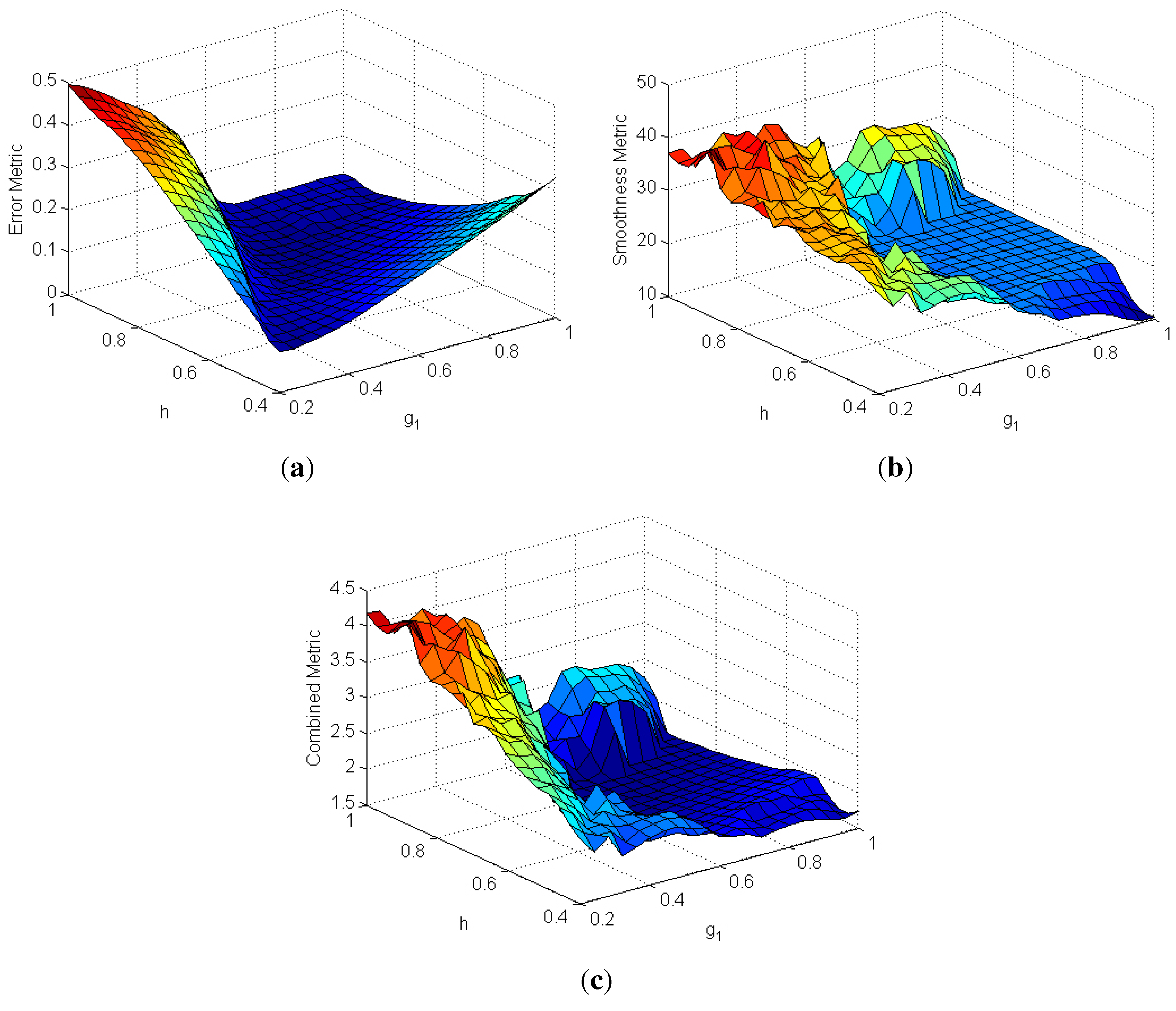
4.1.1. Gain Tuning Metrics

For simulations and experiments, performance metrics were established to ensure that the best set of gains was chosen. The first was an integration of the squared error in angular position as a function of time, giving a total error metric:
ν = 0 T f ( y d y ) 2 d t
where y is the measured joint angle, y d is the desired joint angle and T f is the final time of the test run. Note that the input to the controller is the error signal, e = y d y . While it may seem that this metric is sufficient in tuning the gains, since it minimizes angle deviation, it became quickly apparent that some responses with a lower value of ν also had substantial oscillation about the desired profile, y d . Hence, another error metric was considered to highlight the smoothness of the response. This metric was based on the local curvature of the measured angle:
κ = y ( 1 + y 2 ) 3 / 2
where y is the first time derivative of the measured angle and y is the second time derivative. With the local curvature at each time step, an error metric was computed by integrating κ with respect to time, giving the total curvature:
ω = 0 T f κ d t
This integration provides a single value for comparison, where the response with minimal curvature, or oscillation in the response, is easily identifiable. Having two error metrics now, one based on minimal overall error and one based on minimal oscillation, a combined metric was established drawing on contributions from both individual metrics. Each individual metric was normalized with respect to the minimum value of that metric and weighted with W i as:
J = W ν ν min ν + W ω ω min ω
such that the minimum possible combined value was J = 1 . The weights were chosen as W ν = 0 . 25 and W ω = 0 . 75 to give more precedence to the smoothness of the controlled response than total error, which tended to be undesirably oscillatory alone.

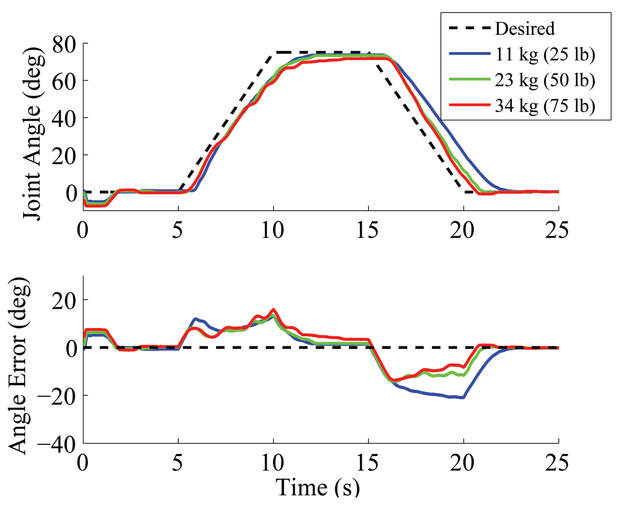
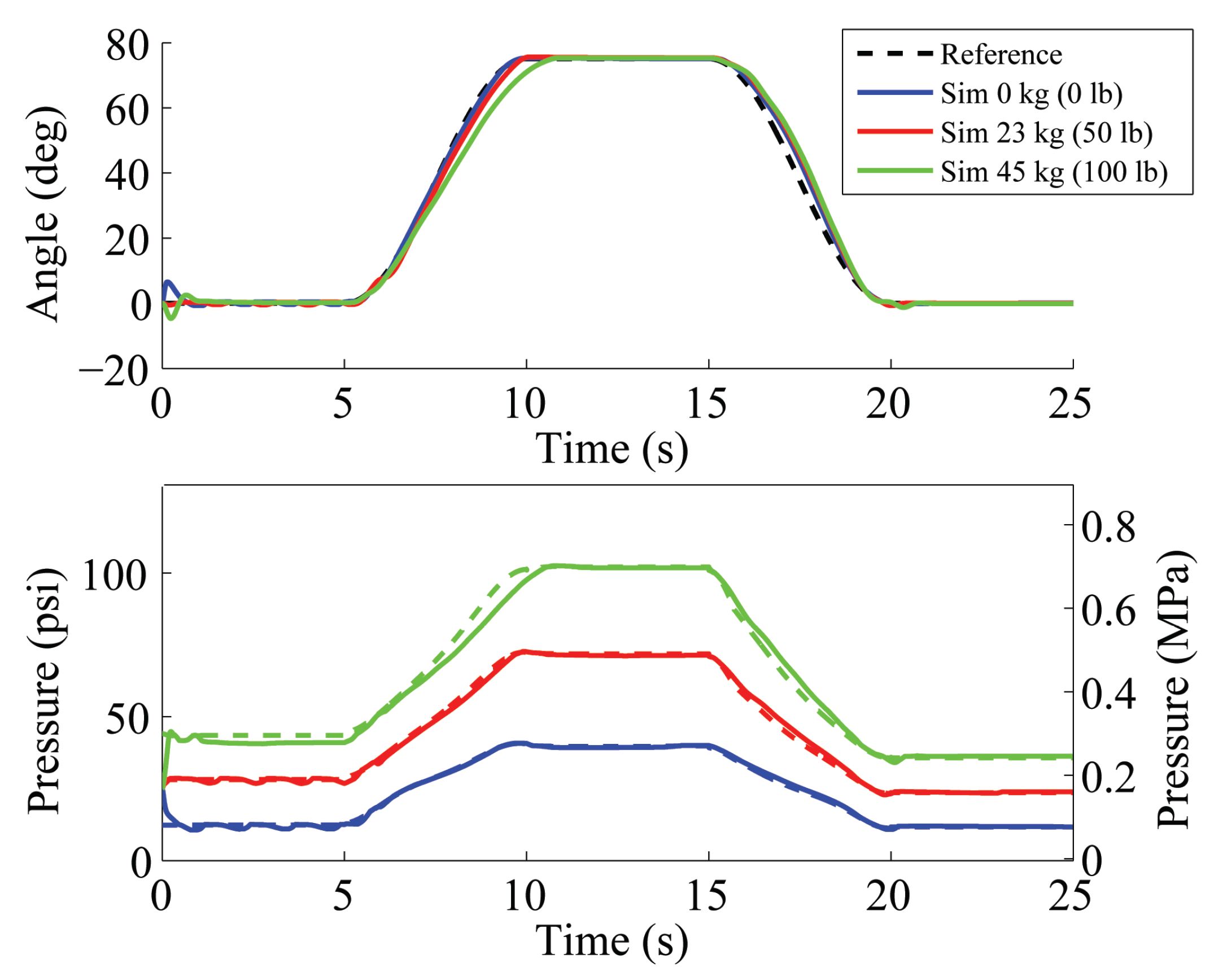
4.1.2. Simulated Trajectory Following

Prior to experimental testing, simulations of the feedback controllers were performed. In each simulation, the elbow joint was commanded to follow a “lift-hold-return” trajectory with 5-s segments; the error and smoothness were monitored, and a combined metric score was calculated. Each of the control gains was varied iteratively, and the set of gains that produced the lowest score was determined to be optimal. Both PID and fuzzy controllers were simulated for various payload weights hung from the tip of the end effector.
Figure 5. Performance metrics as g 1 and h vary ( g 2 = 0 . 6 ) with a 23-kg (50 lb) payload: (a) error metric; (b) smoothness metric; (c) combined metric.
Actuators 03 00041 g005
Figure 5 shows surface contour plots of the performance metrics from fuzzy gain tuning simulations (similar results were also obtained for the PID controller). These plots allow g 1 and h to vary, while g 2 = 0 . 6 is held fixed at the value determined to be optimal for some of the cases. The two individual metrics are shown, along with the combined metric. It is clear that the optimal gain set according to the error metric and smoothness metric are different, producing a combined metric that includes characteristics of both individual metrics and returns a new optimal value ( g 1 = 0 . 45 , h = 0 . 65 ). Note that the area directly surrounding this minimum is smooth and relatively flat, meaning that small deviations from these gains will not cause abrupt changes in behavior. This is important, because a future controller may incorporate gain scheduling in order to account for changes in payload, and as the controller transitions from one set of gains to another, gains may not be at their exact optima at all times.

4.2. Model-Based Control with Output Feedback

Model-based feedforward control was also evaluated in simulation. Some plant parameters (PAM force, friction and arm inertia) were intentionally made slightly different from the controller parameters, so that the model would not match perfectly. Figure 6 shows the trajectory and pressure response for the feedforward controller with fuzzy feedback. It can be seen that both the reference trajectory and pressure are closely followed in all three cases. Control gains are identical for each simulation ( g 1 = 0 . 4 , g 2 = 0 . 3 , h = 0 . 7 , k M = 1 . 0 ). As predicted, larger payloads require higher pressure to achieve the maximum angle. Error during the lift ramp is seen to increase with increasing payload, because the maximum mass flow rate of air decreases as upstream pressure and downstream pressure converge. This effect could be reduced with higher source pressure.
Figure 6. Simulated control, feedforward with fuzzy feedback.
Actuators 03 00041 g006
Figure 7 shows the same trial simulations with PID feedback in place of fuzzy feedback. Again, controller gains are identical for each simulation ( k P = 5 . 0 , k I = 2 . 0 , k D = 0 . 0 , k M = 1 . 0 ). Operation is similar to feedforward control with fuzzy feedback; however, there is slightly increased error in the return stage, which is likely an effect of the integral term delaying a change in direction because of accumulated prior error.
Figure 7. Simulated control, feedforward with PID feedback.
Actuators 03 00041 g007
In both trials, the operation of the model-based controller is smooth and accurate across a large range of payloads and no overshoot is present. The simulations provided a good case for implementation and evaluation on the manipulator hardware.

5. Experimental Evaluation

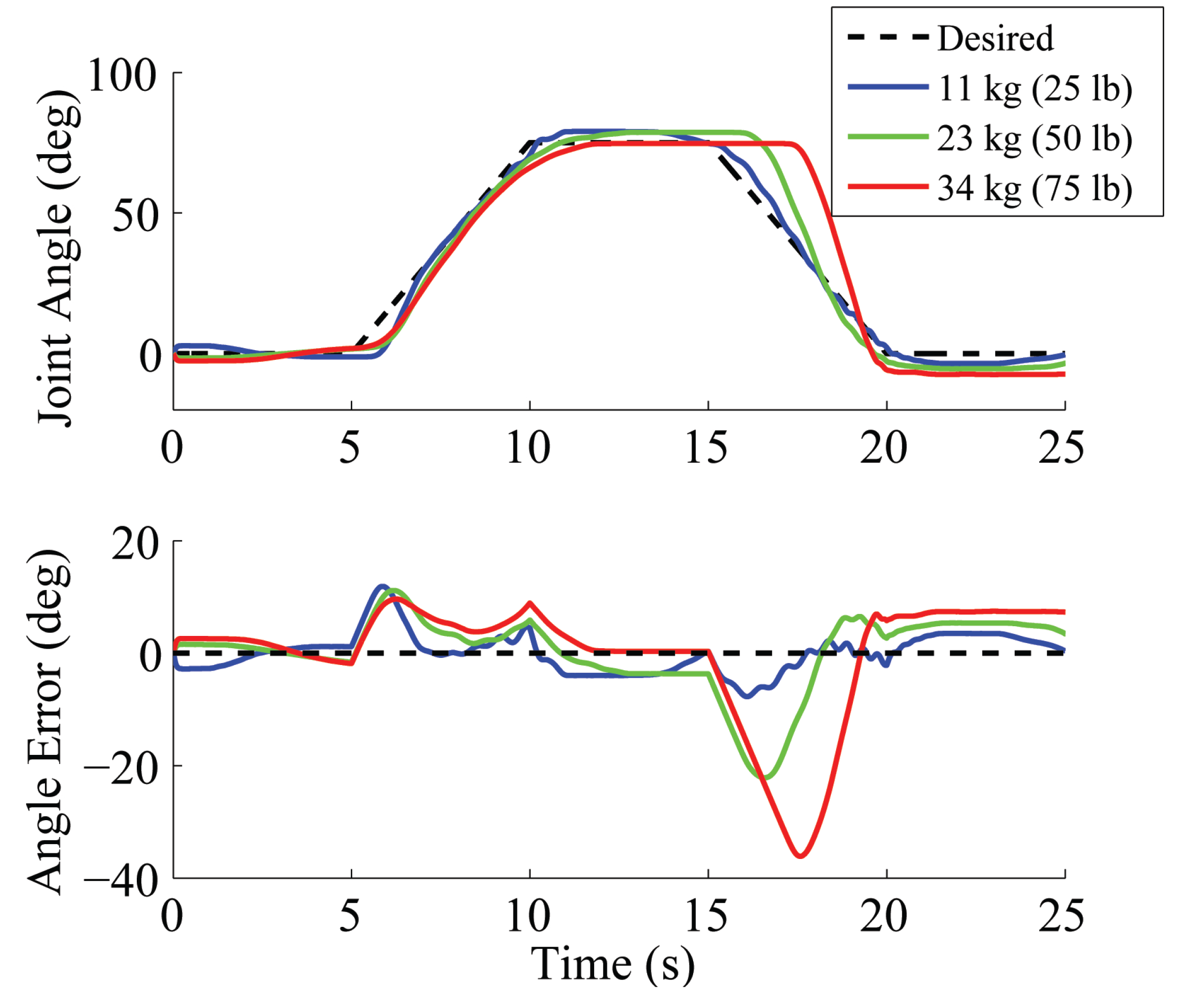
5.1. PID and Fuzzy Control

5.1.1. Experimental Validation

Guided by optimal results from simulation, experimental tests were performed and compared with simulation data. There was generally good correlation between model predictions and experimental measurements, providing validation that the simulation model is sufficient for closed-loop design with the noted PID and fuzzy controllers. Validation of the predicted joint behavior suggested that the simulation model could be extended to other manipulator configurations and control strategies, such as model-based approaches.

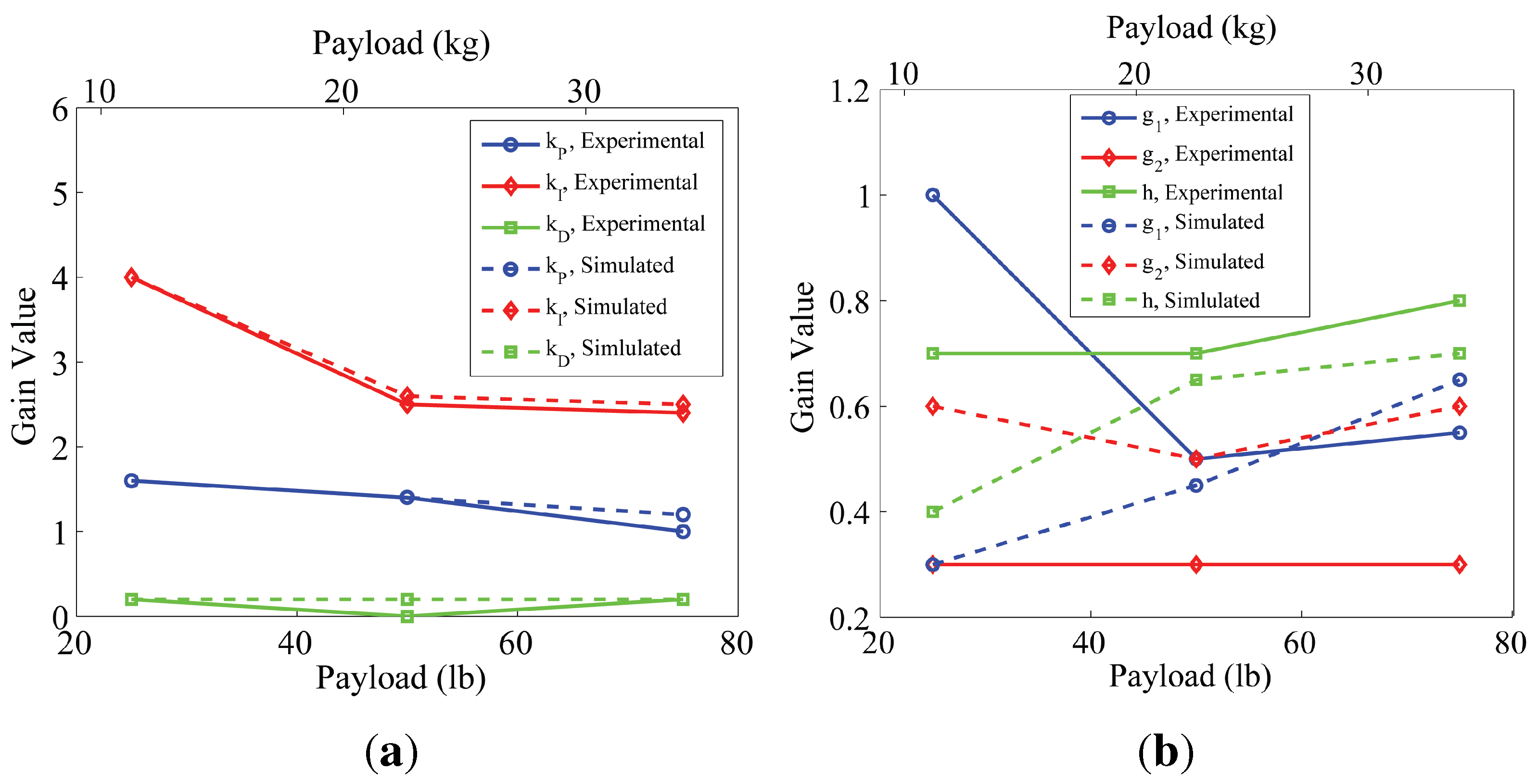
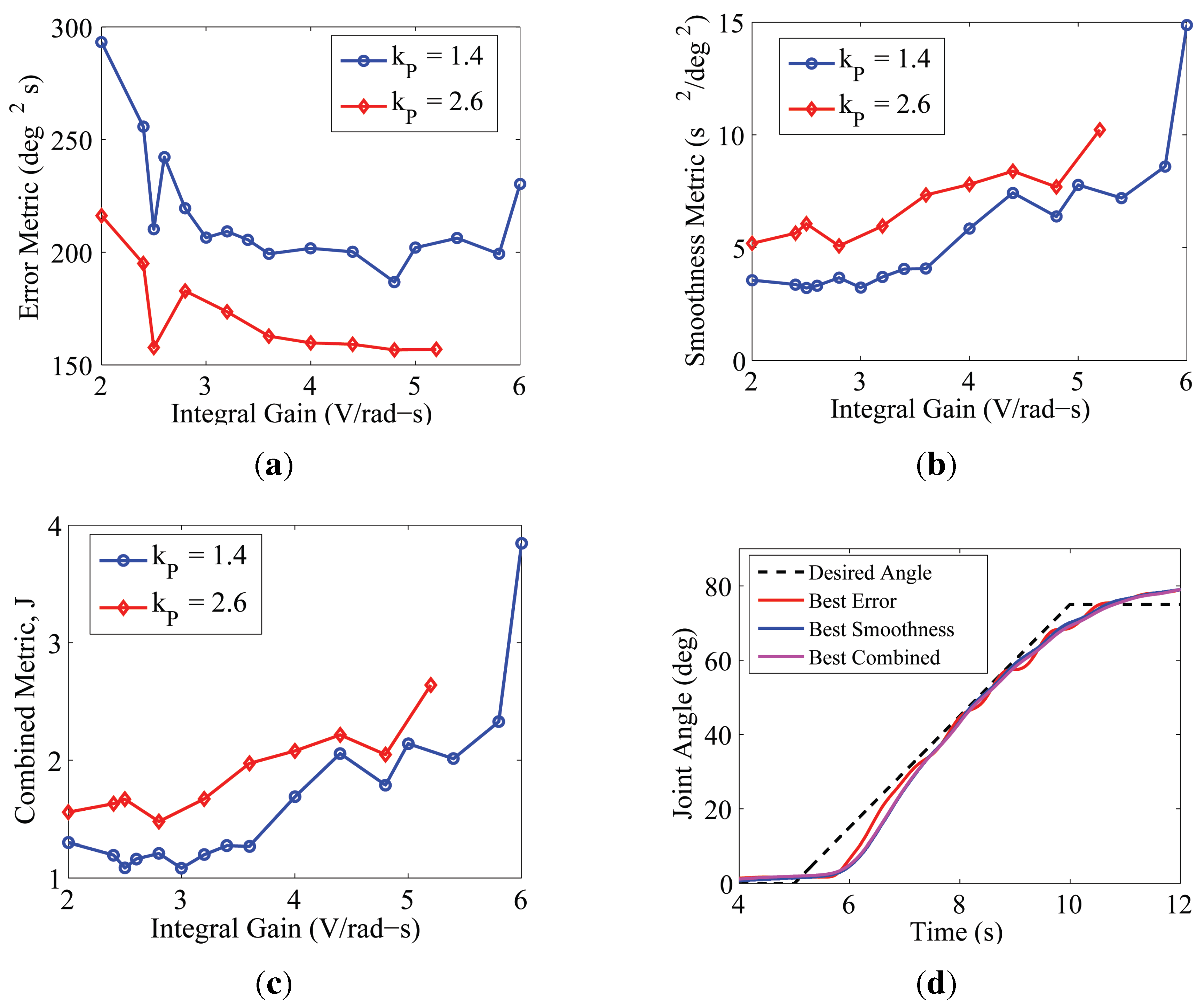
5.1.2. Experimental Gain Tuning

Although simulations with optimal gains showed good correlation with experiments, the differences between the model and actual system indicated that experimental gain tuning could improve performance. Unlike in simulation, evaluating an exhaustive set of gain combinations was not practical, so experimental gain tuning began with the predicted optimal gains and varied these in search of experimental optima. Tuning of the PID controller was performed for three payloads: 11, 23, 34 kg (25, 50, 75 lb). The process began with k P . Next, k I was varied while a highly rated value of k P was held constant. Then, k D was added, and incremental adjustments were made again. Fuzzy controller gains were tuned similarly, in the order of g 1 , h and then g 2 .
Figure 8 shows an example of how the different error metrics guided the selection of different gains as being “optimal” in the experiments. This example is with 23 kg (50 lb) and considers variations in k I with two different values of k P , while k D = 0 . As can be seen for the two individual metrics in Figure 8a,b, each gives a best response (minimum value) with a different value of k P , and that minimum metric value occurs at a different gain value of k I . This is the main purpose for considering the combined (normalized and weighted) metric in Figure 8c. With the weights discussed above, this figure shows that the best overall closed-loop response with respect to these metrics and weights occurs when k P = 1 . 4 and k I = 2 . 5 . To help show the differences in the actual measured time response of the joint rotation angle, Figure 8d has been included, showing the responses with the best gains according to each metric in Figure 8a–c. As seen, “Best Error” follows the “Desired Angle” the closest, but it also has the largest oscillations. “Best Smoothness” and “Best Combined” are much closer to each other, though slightly less accurate than “Best Error,” but both have less oscillatory behavior. This provides an example of the trade-offs considered in tuning the gains.
Figure 8. PID control, integral gain selection with a 23-kg (50 lb) payload: (a) error metric; (b) smoothness metric; (c) combined metric; (d) time response for “best” cases.
Actuators 03 00041 g008
Two data points corresponding to k I = 2 . 5 in Figure 8a seem to be outliers, potentially caused by factors that are specific to this system and the chosen reference trajectory. For instance, this integral gain value could have lead to a buildup of steady-state error that started to rebound just as the reference angle began to increase/decrease, causing the arm to closely follow the reference angle in its upward/downward movement, in effect anticipating system motion and canceling out the time delay. Another possibility is that this specific integral gain value causes the swaying of the payload in a manner that “helps” the controller follow the path. The most obvious outlier ( k P = 2 . 6 , k I = 2 . 5 ) was weeded out because of less impressive performance in terms of the “smoothness metric.” The use of a combined metric helps to reduce anomalies in the data, especially because low error often corresponds to high oscillation. It is possible that the point ( k P = 1 . 4 , k I = 2 . 5 ) would no longer correspond to the optimal set of gains if a different trajectory were chosen, but because it is close to the other local minimum in Figure 8c, ( k P = 1 . 4 , k I = 3 . 0 ), it should be safe to assume good performance for other similar lifting trajectories.
Figure 9 compares the optimal gains determined from simulation and experiment. Figure 9a shows that the PID experimental gains are within a reasonable range of those simulated. The derivative gain is zero or near zero at each payload, and the proportional gain starts just above k P = 1 at 11 kg (25 lb) and decreases with increasing payload. At the minimum payload, the integral gains for both cases are near k I = 4 , but above this payload, there is some deviation, with the experiment showing a downward trend and the simulation showing an upward trend initially before turning downward. Optimal fuzzy control gains are displayed in Figure 9b. The g 1 values and trend from 23 to 34 kg (50 lb to 75 lb) are close, but there is a large difference in the preferred values at 11 kg (25 lb). Both g 2 and h follow experimental trends better, where g 2 stays relatively constant with payload (the values differ up to 2 times), and h shows an increasing trend with payload, with nearly equivalent values at 23 and 34 kg (50 lb and 75 lb). The difference with the small payload may be caused by system parameters involved with the dynamics that were not well-modeled, but were not critical factors at heavy payloads or for PID control. These parameters (damping, friction or payload swinging) are difficult to estimate. The discrepancy in modeling created an optimal region in simulated gain tuning that did not exist for the physical system. Overall, it can be stated that the experimentally determined optimal gains are fairly similar to the optimal gains predicted by the simulation model, though future model refinement may be beneficial.
Figure 9. Experimental vs. simulated optimal gains: (a) PID; (b) fuzzy.
Actuators 03 00041 g009

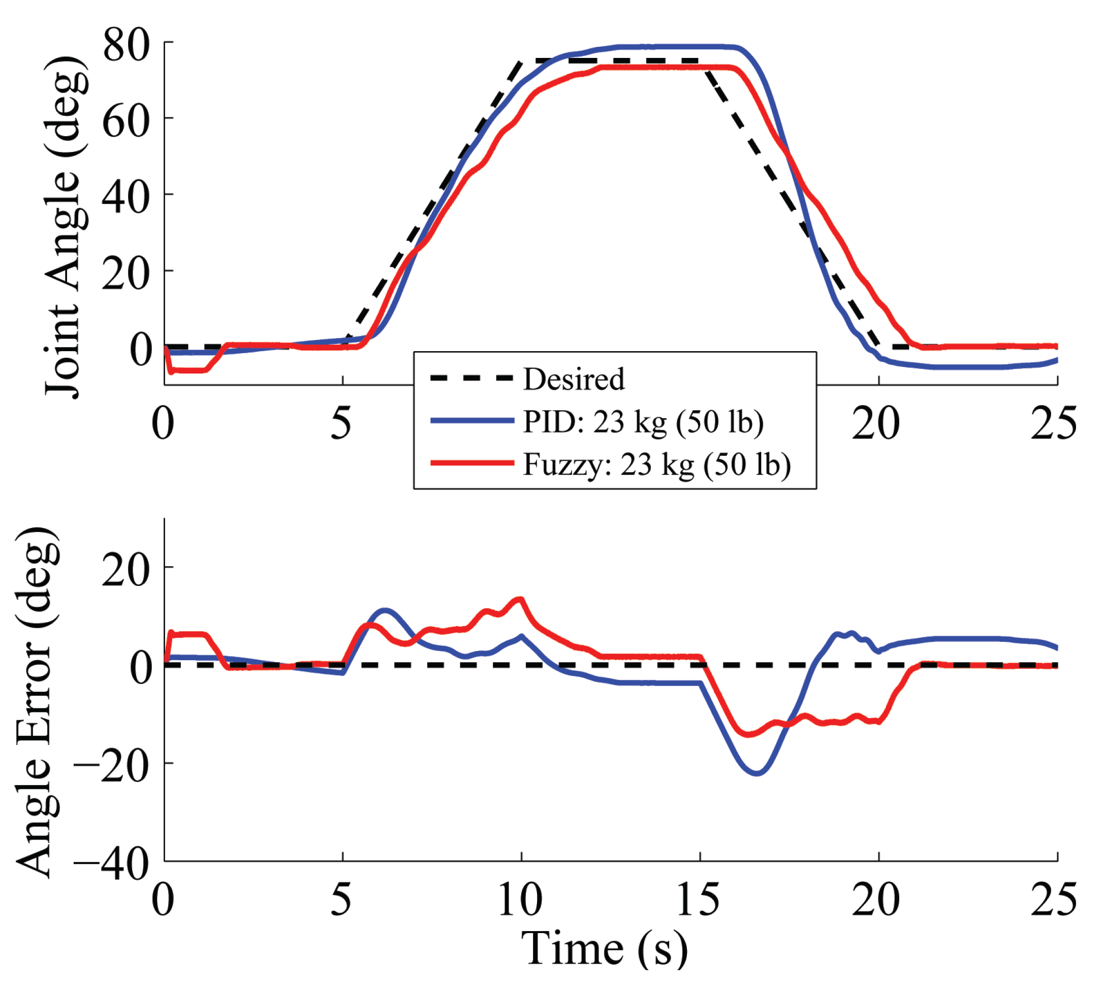
5.1.3. Comparison of Output Feedback Controllers

Figure 10 shows the time histories of lift-hold-return trajectory-following experiments using the experimentally optimized PID gains for three payload weights. In each case, the joint initiated positive rotation with about 1 s of delay and quickly converged to a steady-state during the hold stage. Additional payload prevented contraction until the pressure increased, which slightly added to the delay. Due to the larger weighting on the smoothness metric, oscillations reached acceptable levels, but the total error was slightly larger. The cumulative angle error over the trajectory also increases with payload. Most visible with the PID controller is the undesirably large error in the return stage (arm lowering). With 34 kg (75 lb), this is attributable to integrator windup, when the integral term accumulates a high error, because the arm cannot produce the required torque in this case. Consequently, when the reference changes, the integrator must unwind before the arm can change position. This also causes a considerable overshoot past the rest position when the arm is lowered. This problem could be mitigated by preventing the integral term from increasing over certain bounds. However, an anti-integrator windup will not remove this overshoot phenomenon completely, unless the integral gain is set to zero. Some integral gain is needed to allow PID control to remain smooth, reactive and able to settle to the steady-state. Hence, this is a drawback of the PID control strategy for this system.
Figure 10. PID control with optimized gains.
Actuators 03 00041 g010
Figure 11 displays the results of optimal gains using the fuzzy controller under the same experimental conditions. All three joint angle trajectories are similar in shape, implying minimal change in the lifting behavior with changes in payload weight. There is some undesirable low-frequency oscillation during the lift stage, and the arm, while close, does not quite reach the desired hold angle. There is no overshoot, however, and more gradual movement during the return stage, making the closed-loop tracking appear better overall with the fuzzy controller than the PID controller.
Figure 12 presents a direct comparison of the PID and fuzzy experiments with the 23-kg (50 lb) payload. In lifting the payload, fuzzy control produces more oscillation, but the overshoot seen with the PID controller does not self-correct until after the return stage has begun. The fuzzy controller lags during the lift stage more than with PID, but PID generally reacts more slowly to the return stage (mainly due to integrator windup). The consistent lag of about 0.75 s in each fuzzy control case indicates that introducing a time-shift in the “Desired Angle” to account for the characteristic delay in the system as a type of feedforward correction could decrease error, thereby artificially improving the tracking capability of the manipulator joint. It should also be noted that this type of correction would likely be less beneficial to the PID controller, because it can better track the lift slope, and its major delay is only at the start of the return stage.
Figure 11. Fuzzy control with optimized gains.
Actuators 03 00041 g011
Figure 12. Comparison of optimized experimental PID and fuzzy control, 23-kg (50 lb) payload.
Actuators 03 00041 g012

5.2. Model-Based Control with Output Feedback

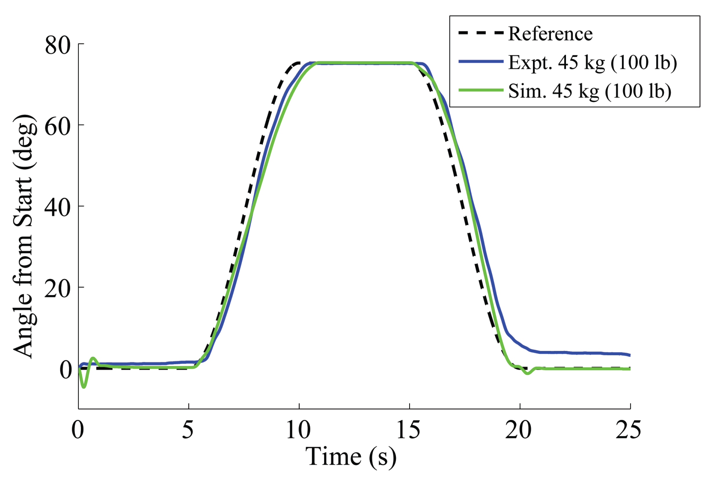
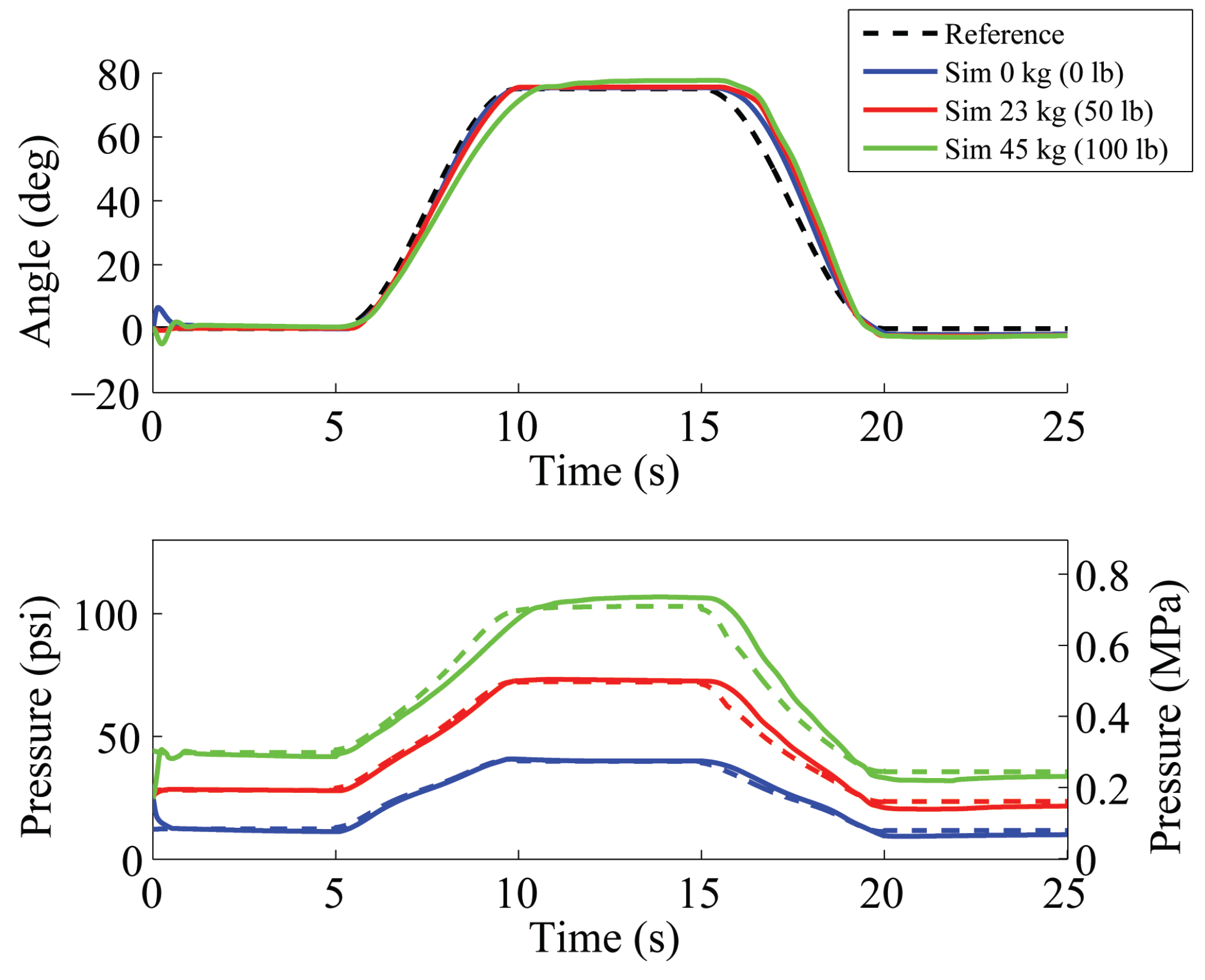
5.2.1. Model Validation

Following successful simulations, the feedforward controller with PID/fuzzy feedback was implemented on the PAM-based manipulator using dSPACE real-time control hardware and software. Figure 13 displays both simulated and experimental results for the same lift-hold-return trajectory with 45 kg (100 lb) and identical system gains ( g 1 = 0 . 4 , g 2 = 0 . 3 , h = 0 . 7 , k M = 0 . 5 ). The only major difference between simulation and experimental results is the final resting angle after the return stage, which maintains a steady-state error even after 5 s in the experiment. The major cause of the discrepancy is that the PAM model is inaccurate at low pressures (<40 psi [0.275 MPa]). Additionally, friction in the joint and hysteresis in the actuators that was not accurately described by the model exaggerate the error.
Figure 13. Simulated and experimental results using feedforward control with fuzzy feedback, 45-kg (100 lb) payload.
Actuators 03 00041 g013

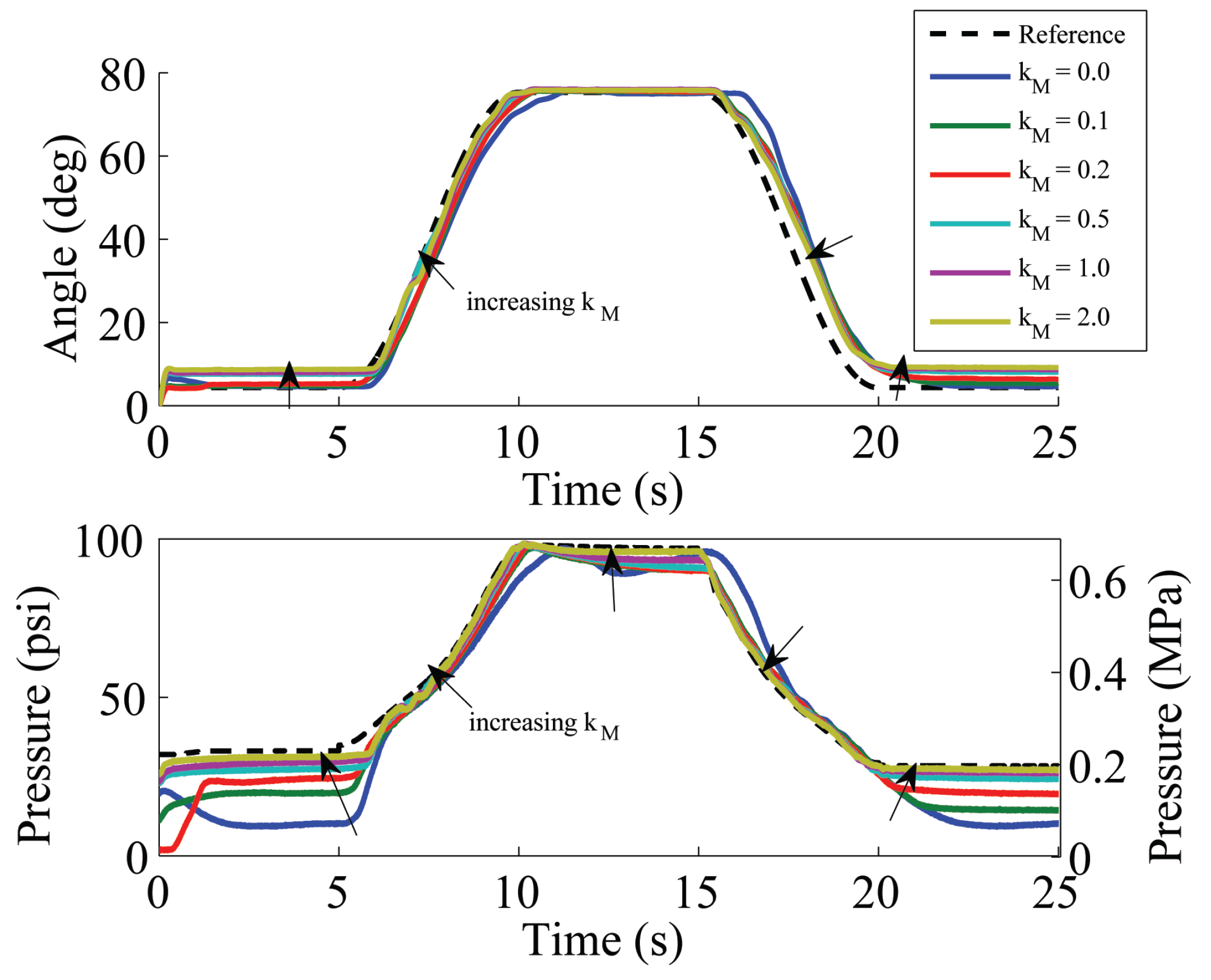
5.2.2. Experimental Analysis of Feedforward Gain

Significant variations in the system response with changing feedforward gain k M warrant a more detailed analysis of this relationship. Figure 14 shows the desired trajectory of several experimental trials varying k M , while the feedback controller gains were fixed ( g 1 = 0 . 45 , g 2 = 0 . 3 , h = 0 . 7 ). With k M = 0 (pure fuzzy feedback), the responsiveness is low, and the lag increases error. However, this case has the lowest steady-state error at the initial/final angle, where the model is inaccurate. In terms of pressure, trials with higher k M follow the predicted pressure (dotted line) more closely. This pressure “trajectory,” representing the model calculation of the needed pressure, is accurate at high pressures, but inaccurate at lower ones. As k M increases, the model aids the system in quickly responding to changes in direction, but the steady-state error at low angles (i.e., low pressures) increases. The optimal gain based on an RMS error over the 25 s interval is k M = 0 . 5 .
Figure 14. Lift-hold-return trajectory while varying model gain k M , 23-kg (50 lb) payload.
Actuators 03 00041 g014

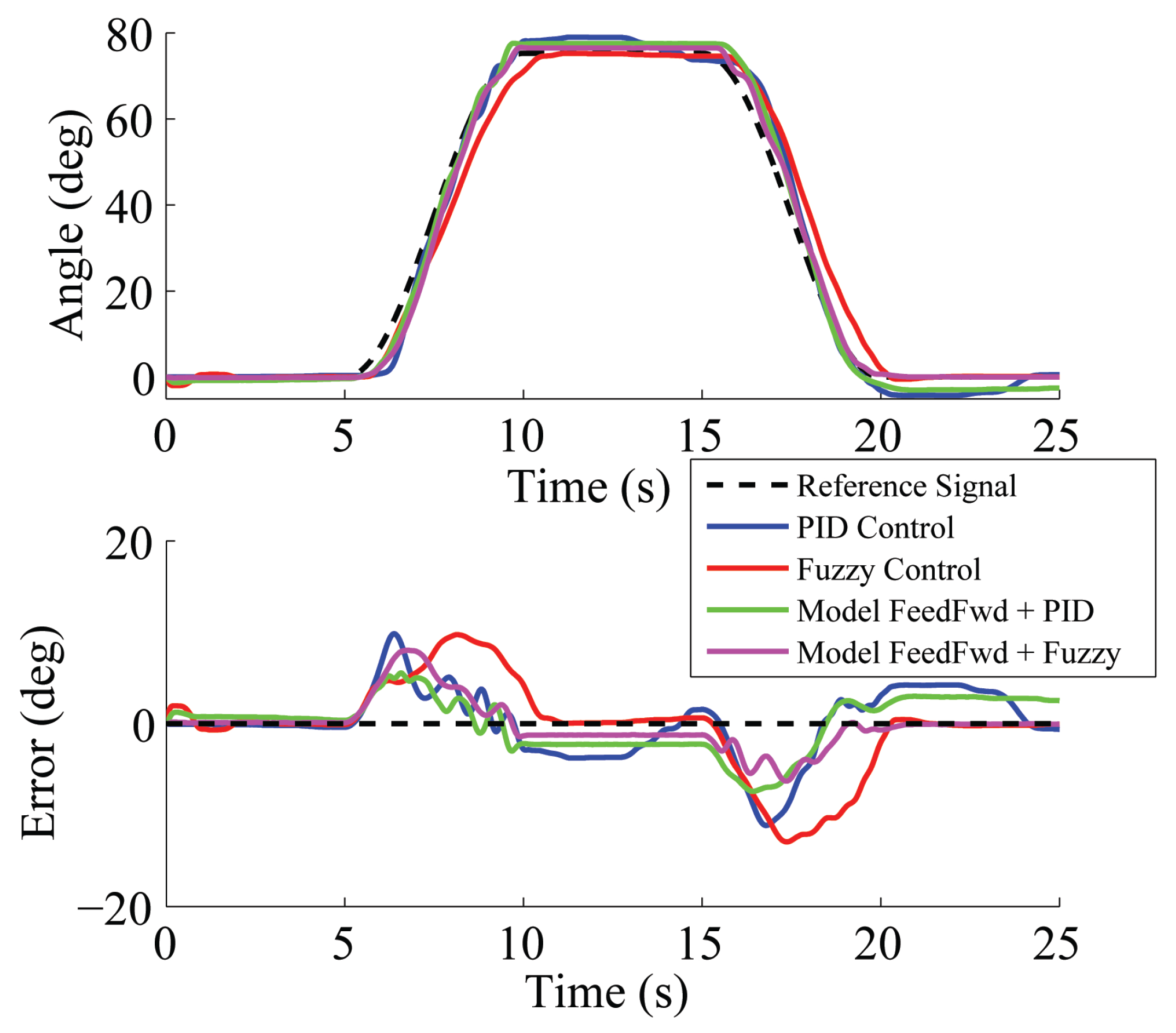
5.3. Discussion of Controllers

Figure 15 compares the response of the four controllers investigated. Two are simple output feedback controllers (PID and fuzzy) and two are model-based feedforward controllers augmented with PID and fuzzy feedback ( k M = 0 . 5 ). It is clear that the feedforward term increases accuracy in all stages of the response. Feedforward with PID control also decreases oscillation in comparison to PID control alone.
Responsiveness to change in direction is also improved with model-based feedforward control. In this manner, the feedforward term is similar to an increase in the feedback gains. Unlike increasing feedback gains, however, the system does not exhibit more oscillation. While there is a large time delay in joint angle, there is significantly less time delay in achieving desired pressure. Therefore, the convergence of actual and predicted pressure occurs smoothly and without overshoot.
Figure 15. Comparison of all four control techniques studied, 11-kg (25 lb) payload.
Actuators 03 00041 g015
A well-known concern with PAM-based systems is undesired energy storage in the form of spring force when the system is deflected from its equilibrium [42,43]. However, the feedforward controller presented in this study is able to respond safely to abrupt changes in deflection and payload. Figure 16 illustrates the angle response to the addition and subsequent removal of a 27 kg (60 lb) payload. The system deflects by about 10 deg, but soon recovers to the desired angle. A video provided as supplemental content shows the elbow joint response to various disturbances, such as payload addition/subtraction and human disturbances.
Figure 16. Elbow angle response to the addition/subtraction of a 27 kg (60 lb) payload, feedforward control with PID feedback. Also, see multimedia video content.
Actuators 03 00041 g016

6. Conclusions

This study investigated the use of several controllers on the elbow joint of a heavy-lift two degree-of-freedom manipulator actuated by pneumatic artificial muscles. Each method was designed, simulated and implemented on experimental hardware. Output feedback (PID and fuzzy) controllers were examined, as well as model-based feedforward controllers augmented with output feedback. A model of the manipulator, actuators and airflow dynamics was developed to enable simulation control studies and gain tuning. Trajectory-following simulations and preliminary gain optimizations were conducted with the system model, where it was determined that a combined performance metric weighing angle error and smoothness was necessary to achieve the desired response.
Using real-time interface software and hardware, the controllers were experimentally tested. Refinement of each technique was performed through an experimental gain tuning procedure, where it was learned that the predicted optimal gains were fairly accurate for PID and fuzzy control. When further tuned experimentally, output feedback controllers demonstrated robustness to variations in payload weight over a large range of motion and were shown to follow basic lift-hold-return trajectories with small oscillation, lag and overshoot. PID control demonstrated higher accuracy and smoothness than fuzzy control during the lifting phase, but was more susceptible to overshoot and lag while holding or lowering the weight. The overall performance with output feedback alone suggested the need for improvement.
To improve closed-loop performance, model-based feedforward control augmented with output feedback was implemented. This approach was shown to produce smooth and precise motions with low error for varying payloads, even without changing control gains. The feedforward gain was also varied to demonstrate its effect on the response, where it was shown that there is an optimal gain setting. There is room for improvement in model accuracy at low pressures, which would allow for higher feedforward gain values and would further improve the tracking ability of this control strategy.
Due to the complicated control structure and the unmodeled or unanticipated dynamics in the system, it is difficult to formally establish the stability of the system. When the open-loop system is in static equilibrium at any point between the joint limits, the system is stable because of the large passive damping component inherent to pneumatic muscles. This damping helps to ensure that PAMs are stable in well-tuned closed-loop feedback systems. However, to guard against potential instability when a controller is employed, one should perform a careful analysis to determine a stable range of control gain values over the known range of payloads.
Future improvements to consider include a dynamic PAM model that better accounts for nonlinearities, such as hysteresis, an adaptive element that responds to abrupt changes in payload in real-time and automated trajectory planning. Another challenge is to extend this system to multiple degrees-of-freedom, where coupling between joints and three-dimensional motion increases the complexity and small model errors may propagate to links farther down the manipulator.

Supplementary Material

Supplementary File 1

Acknowledgments

This work was supported by the U.S. Army Medical Research and Materiel Command under Contract No. W81XWH-10-C-0014 (technical monitor: Gary Gilbert). The views, opinions and/or findings contained in this report are those of the authors and should not be construed as an official Department of the Army position, policy or decision, unless so designated by other documentation.

Author Contributions

This work resulted from a Small Business Innovation Research (SBIR) contract that was a collaboration between industry and academia, wherein Dr. Kothera was the Principal Investigator from the industry prime contractor. Dr. Wereley was the Principal Investigator for the university subcontract, and the work performed by Mr. Robinson was part of his research in pursuit of a doctoral degree, under the advisement of Dr. Wereley. Dr. Kothera established the system requirements and performance metrics, prepared the initial system model, tuned the PID controllers, and implemented the first control system experimentally. Mr. Robinson refined the system model, and designed and implemented the fuzzy controller and model-based controllers in simulation and experiment. Dr. Wereley guided the research throughout and aided the controller selection and analysis. All three authors contributed to the writing and editing of the manuscript, in efforts commensurate with the listed order of authorship.

Conflicts of Interest

The authors declare no conflict of interest.

References

  1. Shin, D.; Sardellitti, I.; Khatib, O. A hybrid actuation approach for human-friendly robot design. In Proceedings of the IEEE International Conference on Robotics and Automation, Pasadena, CA, USA, 19–23 May 2008; pp. 1747–1752.
  2. Klute, G.K.; Czerniecki, J.M.; Hannaford, B. Artificial muscles: Actuators for biorobotic systems. Int. J. Robot. Res. 2002, 21, 295–309. [Google Scholar] [CrossRef]
  3. Schulte, H. The Application of External Power in Prosthetics and Orthotics; Technical Report; National Academy of Sciences: Washington, DC, USA, 1961. [Google Scholar]
  4. Caldwell, D.G.; Tsagarakis, N. Biomimetic actuators in prosthetic and rehabilitation applications. Technol. Health Care 2002, 10, 107–120. [Google Scholar] [PubMed]
  5. Knestel, M.; Hofer, E.P.; Barillas, S.K.; Rupp, R. The artificial muscle as an innovative actuator in rehabilitation robotics. In Proceedings of the 17th IFAC World Congress, Seoul, Korea, 6–11 July 2008; pp. 773–778.
  6. Li, X.; Xia, H.; Guan, T. Development of legs rehabilitation exercise system driven by pneumatic muscle actuator. In Proceedings of the IEEE International Conference on Bioinformatics and Biomedical Engineering, Shanghai, China, 16–18 May 2008; pp. 1309–1311.
  7. Tondu, B.; Ippolito, S.; Guiochet, J.; Daidie, A. A seven-degrees-of-freedom robot-arm driven by pneumatic artificial muscles for humanoid robots. Int. J. Robot. Res. 2005, 24, 257–274. [Google Scholar] [CrossRef]
  8. van der Linde, R. Design, analysis, and control of a low power joint for walking robots, by phasic activation of McKibben muscles. IEEE Trans. Robot. Autom. 1999, 15, 599–604. [Google Scholar] [CrossRef]
  9. Zheng, H.; Shen, X. Double-acting sleeve muscle actuator for bio-robotic systems. Actuators 2013, 2, 129–144. [Google Scholar] [CrossRef] [PubMed]
  10. Klute, G.K.; Hannaford, B. Accounting for elastic energy storage in McKibben artificial muscle actuators. ASME J. Dyn. Syst. Meas. Control 2000, 122, 386–388. [Google Scholar] [CrossRef]
  11. Ferraresi, C.; Franco, W.; Bertetto, A.M. Flexible pneumatic actuators: A comparison between the McKibben and the straight fibres muscles. J. Robot. Mechatron. 2001, 13, 56–63. [Google Scholar]
  12. Shan, Y.; Philen, M.P.; Bakis, C.E.; Wang, K.; Rahn, C.D. Nonlinear-elastic finite axisymmetric deformation of flexible matrix composite membranes under internal pressure and axial force. Compos. Sci. Technol. 2006, 66, 3053–3063. [Google Scholar] [CrossRef]
  13. Van Damme, M.; Beyl, P.; Vanderborght, B.; Van Ham, R.; Vanderniepen, I.; Versluys, R.; Daerden, F.; Lefeber, D. Modeling hysteresis in pleated pneumatic artificial muscles. In Proceedings of the 2008 IEEE Conference on Robotics, Automation and Mechatronics, Chengdu, China, 21–24 September 2008; pp. 471–476.
  14. Davis, S.; Caldwell, D.G. Braid effects on contractile range and friction modeling in pneumatic muscle actuators. Int. J. Robot. Res. 2006, 25, 359–369. [Google Scholar] [CrossRef]
  15. Caldwell, D.; Medrano-Cerda, G.; Goodwin, M. Control of pneumatic muscle actuators. IEEE Control Syst. Mag. 1995, 15, 40–48. [Google Scholar] [CrossRef]
  16. Ahn, K.; Nguyen, H. Intelligent switching control of a pneumatic muscle robot arm using learning vector quantization neural network. Mechatronics 2007, 17, 255–262. [Google Scholar] [CrossRef]
  17. Wu, J.; Huang, J.; Wang, Y.; Xing, K.; Xu, Q. Fuzzy PID control of a wearable rehabilitation robotic hand driven by pneumatic muscles. In Proceedings of the IEEE 2009 International Symposium on Micro-NanoMechatronics and Human Science, Nagoya, Japan, 9–11 November 2009; pp. 408–413.
  18. Yeh, T.J.; Wu, M.J.; Lu, T.J.; Wu, F.K.; Huang, C.R. Control of McKibben pneumatic muscles for a power-assist, lower-limb orthosis. Mechatronics 2010, 20, 686–697. [Google Scholar] [CrossRef]
  19. Beyl, P.; Van Damme, M.; Cherelle, P.; Lefeber, D. Safe and compliant guidance in robot-assisted gait rehabilitation using proxy-based sliding mode control. In Proceedings of the 2009 IEEE International Conference on Rehabilitation Robotics, Kyoto, Japan, 23–26 June 2009; pp. 277–282.
  20. Sciavicco, L.; Sciliano, B. Modeling and Control of Robot Manipulators; Springer: London, UK, 2000. [Google Scholar]
  21. Zhu, X.; Tao, G.; Yao, B.; Cao, J. Adaptive robust posture control of parallel manipulator driven by pneumatic muscles with redundancy. IEEE/ASME Trans. Mechatron. 2008, 13, 441–450. [Google Scholar]
  22. Ganguly, S.; Garg, A.; Pasricha, A.; Dwivedy, S. Control of pneumatic artificial muscle system through experimental modelling. Mechatronics 2012, 22, 1135–1147. [Google Scholar] [CrossRef]
  23. Nho, H.; Meckl, P. Intelligent feedforward control and payload estimation for a two-link robotic manipulator. IEEE/ASME Trans. Mechatron. 2003, 8, 277–283. [Google Scholar] [CrossRef]
  24. Fateh, M.M.; Izadbakhsh, A. Robust control of a high-speed manipulator in state space. Int. J. Aerosp. Mech. Eng. 2007, 1, 38–43. [Google Scholar]
  25. Young, K.; Utkin, V.; Ozguner, U. A control engineer’s guide to sliding mode control. IEEE Trans. Control Syst. Technol. 1999, 7, 328–342. [Google Scholar] [CrossRef]
  26. Slotine, J.J.; Li, W. Applied Nonlinear Control; Prentice Hall: Englewood Cliffs, USA, 1991. [Google Scholar]
  27. Slotine, J.J. On the Adaptive Control of Robot Manipulators. Int. J. Robot. Res. 1987, 6, 49–59. [Google Scholar] [CrossRef]
  28. Carbonell, P.; Jiang, Z.; Repperger, D. Nonlinear control of a pneumatic muscle actuator: backstepping vs. sliding-mode. In Proceedings of the 2001 IEEE International Conference on Control Applications, Mexico City, Mexico, 5–7 September 2001; Volume 2, pp. 167–172.
  29. Cai, D.; Dai, Y. A sliding mode controller for manipulator driven by artificial muscle actuator. Electron. Commun. Jpn. (Part III: Fundam. Electron. Sci.) 2003, 86, 57–64. [Google Scholar] [CrossRef]
  30. Lilly, J.H. Adaptive tracking for pneumatic muscle actuators in bicep and tricep configurations. IEEE Trans. Neural Syst. Rehabil. Eng. 2003, 11, 333–339. [Google Scholar] [CrossRef] [PubMed]
  31. Nouri, A.; Gauvert, C.; Tondu, B.; Lopez, P. Generalized variable structure model reference adaptive control of one-link artificial muscle manipulator in two operating modes. In Proceedings of IEEE International Conference on Systems, Man and Cybernetics, San Antonio, USA, 2–5 October 1994; Volume 2, pp. 1944–1950.
  32. Xing, K.; Xu, Q.; Huang, J.; Wang, Y.; He, J.; Wu, J. Tracking control of pneumatic artificial muscle actuators based on sliding mode and non-linear disturbance observer. IET Control Theory Appl. 2010, 4, 2058–2070. [Google Scholar] [CrossRef]
  33. Shen, X. Nonlinear model-based control of pneumatic artificial muscle servo systems. Control Eng. Pract. 2010, 18, 311–317. [Google Scholar] [CrossRef]
  34. Aschemann, H.; Schindele, D. Sliding-mode control of a igh-speed linear axis driven by pneumatic muscle actuators. IEEE Trans. Ind. Electron. 2008, 55, 3855–3864. [Google Scholar] [CrossRef]
  35. Braikia, K.; Chettouh, M.; Tondu, B.; Acco, P.; Hamerlain, M. Improved control strategy of 2-sliding controls applied to a flexible robot arm. Adv. Robot. 2011, 25, 1515–1538. [Google Scholar] [CrossRef]
  36. Robinson, R.M.; Kothera, C.S.; Woods, B.K.S.; Vocke, R.D.; Wereley, N.M. High specific power actuators for robotic manipulators. J. Intell. Mater. Syst. Struct. 2011, 22, 1501–1511. [Google Scholar] [CrossRef]
  37. Tonietti, G.; Schiavi, R.; Bicchi, A. Design and control of a variable stiffness actuator for safe and fast physical human/robot interaction. In Proceedings of the IEEE International Conference on Robotics and Automation, Barcelona, Spain, 18–22 April 2005; pp. 526–531.
  38. Richer, E.; Hurmuzulu, Y. A high performance pneumatic force actuator system part 1—Nonlinear mathematical model. ASME J. Dyn. Syst. Meas. Control 2001, 122, 416–425. [Google Scholar] [CrossRef]
  39. Kothera, C.S.; Jangid, M.; Sirohi, J.; Wereley, N.M. Experimental characterization and static modeling of McKibben actuators. ASME J. Mech. Des. 2009, 131, 091010. [Google Scholar] [CrossRef]
  40. Passino, K. Fuzzy Control; Addison Wesley Longman: Menlo Park, USA, 1998; pp. 1–492. [Google Scholar]
  41. Robinson, R.M.; Wereley, N.M.; Kothera, C.S. Control of a heavy-lift robotic manipulator with pneumatic artificial muscles. In Proceedings of the AIAA Structures, Structural Dynamics, and Materials Conference, Honolulu, HI, USA, 23–26 April 2012; pp. 1–14.
  42. Van Damme, M.; Beyl, P.; Vanderborght, B.; Versluys, R.; Ham, R.; Vanderniepen, I.; Daerden, F.; Lefeber, D. The safety of a robot actuated by pneumatic muscles—A case study. Int. J. Soc. Robot. 2010, 2, 289–303. [Google Scholar] [CrossRef]
  43. Haddadin, S.; Albu-Schaffer, A.; Eiberger, O.; Hirzinger, G. New insights concerning intrinsic joint elasticity for safety. In Proceedings of the IEEE/RSJ International Conference on Intelligent Robots and Systems, Taipei, Taiwan, 18–22 October 2010; pp. 2181–2187.

