1. Introduction
Active magnetic bearings (AMBs) support a rotating shaft with a magnetic field generated by electromagnets controlled in feedback. The shaft, consequently, is levitated in an air gap and has no physical contacts. This has the advantages of no friction losses, less maintenance, longer life, no need for lubrication, etc. Practical AMB technology has been commercially available for many years. However, the application of AMBs in industry remains limited. This is due, in part, to the lack of familiarity with AMBs among the body of practicing engineers. As a result, end users are reluctant to purchase AMB systems for fear of the consequences of levitation failure, such as damage to the shaft, housing, or process. This work proposes an AMB control method that provides robust levitation recovery in the event of the acute loss of levitation.
In general, there are two types of AMB failures; internal and external faults [
1]. Internal faults are associated with the components of the AMB. An example of an internal fault is a position sensor failure, which would result in a severing of the feedback control loop and loss of levitation. The prevention of internal faults has been addressed by the robustness of individual components and, in certain cases, component redundancy, such as having more magnetic poles than is necessary. There has also been research on proper control of redundant AMB systems that are experiencing component failure [
2]. Conversely, external faults are those that arise from factors outside of the AMB system. For example, a shaft supported on AMBs that processes natural material may encounter an aberration in the material’s consistency, which applies a onetime unsupportable load. Another example of an external fault is a momentary loss of power. In both cases, the components of the AMB system remain intact.
The control solution proposed in the current work addresses the problem of external faults. In the event of an external fault, there is an acute loss of levitation and, although there are no sustained component failures, recovery of levitation may be prevented by two phenomena. First, the fact that the rotor is at a large deflection can drive the control current into the saturation region [
3]. Saturation of control actuation is widely known to have adverse effects on stability. The situation is exacerbated by the coincidence of unbalance forces. Second, shaft contact with the touchdown (TD) bearings while rotating will impart other forces on the rotor and may result in a so-called contact mode of vibration [
4]. TD bearings are usually traditional bearings that are oversized for the shaft and do not touch the shaft during levitation but rather catch the shaft in the event of levitation failure. A contact mode is a non-linear but stable mode of vibration of the rotor in intermittent contact with the TD bearings. Contact modes are sustained by the motor feeding energy into the system. Different types of contact modes are possible, including forward whirl (continuous sliding), backward whirl (continuous rolling), and repeated impact (bouncing in a pattern). Whether and which type of contact mode occurs depends on many factors such as unbalance magnitude and angle, running speed, TD bearing parameters such as stiffness and friction, free rotor natural frequencies, etc. The levitation recovery control method proposed and demonstrated in this work uses the robust control strategy
μ-synthesis, which is model-based. These two phenomena, which may prevent levitation recovery while rotating, are taken into account with the system model such that the synthesized control is able to achieve relevitation.
This development is novel compared to typical robust controllers for AMBs such as
μ-synthesis [
5] and robust
H∞ [
6], which can guarantee stability and performance inside the specified operating region (including deflection, load, rotor speed, etc.), utilizing parametric uncertainties and performance weights cast as physical limits on input and output signals, but have no consideration for stability or performance if that operating region is violated in any way. Once the linear control law is designed, that law is enforced regardless of whether the situation it was synthesized for is actually the case. For a simple example, consider an AMB controller that is designed to support a certain load with deflection limited to 10 µm and current limited to 10 A. Assume that, after robust controller synthesis, the resulting controller has a stiffness of 1 A/µm. If, during an acute levitation failure, the rotor is temporarily at 100 µm deflection, the robust controller will attempt to send 100 A to the AMB coil. This may saturate the current limit of the hardware and the formerly robust system is actually uncontrollable.
Much of the existing body of literature in the area of control for relevitation addresses the synchronous disturbance due to TD bearing contact, e.g., [
7,
8,
9]. Therefore, algorithms similar to those for synchronous unbalance compensation have been developed. Good experimental results have been obtained using these approaches; however, a period of automatic disturbance learning is often required, which diminishes their practicality. There have also been efforts in the area of control of actuated TD bearings towards levitation recovery such as [
10]. More similar to the method proposed in this work is [
11], which implements a switching algorithm for an AMB controller manually tuned for levitation recovery of an industrial system. Levitation fault recovery with differential flatness control using noise filtering and derivative estimation through B-Splines has also been studied [
12], although no TD bearing interaction was considered. That approach naturally lends itself to non-linear systems due to the parameterization afforded by the concept of differential flatness. However, the method proposed in the current study is not directly compared to non-linear control methods. Preliminary results for the current study were presented in [
13].
The paper is structured as follows:
Section 2 covers the materials and methods used to develop and demonstrate the proposed levitation recovery control, including an explanation of
μ-synthesis and its application for levitation recovery, the experimental test rig, crafting of the contact force performance weight, and details of controller synthesis for the test rig. Then,
Section 3 presents results of controller synthesis and experimental implementation of the proposed method on the test rig.
Section 4 gives discussion of the significance of the proposed technique and findings.
2. Materials and Methods
This section covers the materials and methods used in development and experimental demonstration of the proposed AMB levitation recovery technique, starting with a brief explanation of μ-synthesis robust controller design. The application of μ-synthesis to controller design for a typical AMB system under normal operating conditions is discussed. Then, the way that procedure is modified to ensure relevitation in the event of momentary failure is explained. Details of the experimental AMB test rig on which the proposed technique is demonstrated are then presented. TD bearing contact forces are estimated through the tuning of a numerical simulation with a simple TD bearing model to drop test data. The contact forces are used to craft a frequency dependent performance weight for synthesis of the recovery controller. Finally, the remaining details of the controller synthesis for the test rig are reported.
2.1. μ-Synthesis Robust Controller Design for Typical AMB Operation and Levitation Recovery
The controller design strategy μ-synthesis was developed to accommodate a system with structured uncertainties. The controller synthesis is carried out with an uncertain plant model using the concepts of liner fractional transformation (LFT) and the structured singular value μ. These tools allow for consideration of multiple parametric uncertainties at the points where they appear in the model, including the magnitude and type of each uncertainty and therefore any interactions between them. Consequently, a robust closed-loop can be designed which is not overly conservative at the cost of performance.
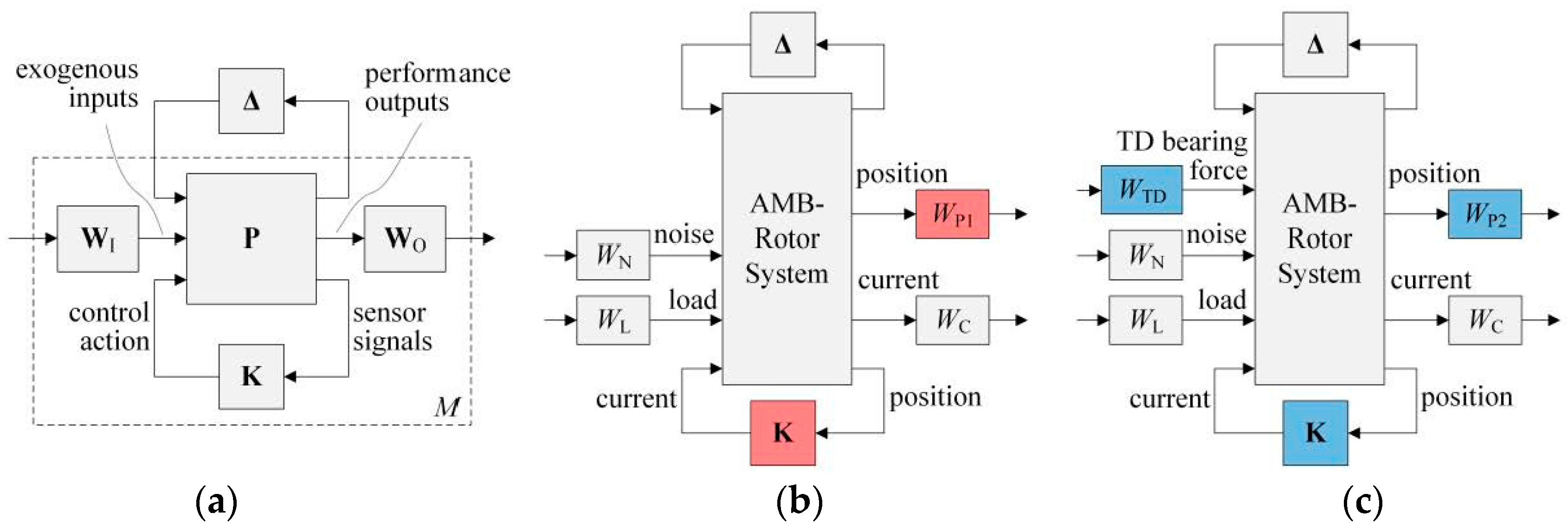
The
μ-synthesis problem formulation for a generalized system is shown in
Figure 1a where
P is the plant,
K is the controller, and
Δ is the uncertain matrix. The structure of matrix
Δ is a result of where each parametric uncertainty occurs in the system model.
The weights
WI and
WO are transfer function matrices that are selected to stipulate the frequency dependent performance from the closed-loop system. The matrix
M is found as the lower LFT,
Fl, of the weighted plant
P′ and the controller.
The
μ-synthesis framework is then cast with the upper LFT of the weighted closed-loop with the uncertainty perturbation, which maps disturbance input
w to performance response
z.
The smallest perturbation matrix Δ, as evaluated with the maximum singular value, which has the defined structure
Δ and which destabilized the system
M, yields the structured singular value
μ.
It is the structured singular value from which μ-synthesis is named.
The controller synthesis procedure seeks to find a controller by iterating to minimize
μ(
M). If the resulting
μ-value is less than unity, it indicates that a greater than allowed uncertainty perturbation is required to destabilize the system. Therefore, the system closed-loop with the synthesized controller is stable and robust to the bounded uncertainties. For a derivation and thorough discussion of
μ-synthesis, the reader is referred to the excellent tomes [
14,
15].
There are many specialized applications of
μ-synthesis for control of AMBs, which take advantage of the model-based nature of
μ-synthesis, such as for machining chatter attenuation [
16], machining tooltip tracking [
17], and hydrodynamic bearing oil-whip stabilization [
18]. However, for a basic AMB system, control is mainly concerned with stabilizing the inherently unstable open-loop and creating practical bearing stiffness in the presence of the flexible modes of the rotor and gyroscopic effect. Therefore,
μ-synthesis for a basic AMB system is as illustrated in
Figure 1b. The nominal plant to be controlled is the AMB-Rotor System. This consists of a finite element (FE) model of the rotor, four radial AMB forces that are linearized and expressed as current and position stiffnesses, and an amplifier model, which quantifies the AMB slew-rate and delays due to digital implementation. The parametric uncertainty perturbations account for AMB linearization errors and a varying running speed. An exogenous input and performance output are defined to achieve bearing stiffness and are physical load and allowable deflection, respectively. The load is external load on the rotor (often taken at the AMB force center location for convenient plant assembly) and position is the rotor lateral deflection (often taken at the AMB sensor location for convenient posteriori evaluation). The performance weight
WL on load is crafted to account for rotor weight at low frequency and unbalance load across the operational speed range and then roll off at high frequencies outside of the range of interest. The weight on position
WP1 is crafted to require small deflection at low frequency and a practical orbit size across the operational speed range before rolling up at high frequency. The noise exogenous input is disturbance on the four sensor signals and is weighted to reflect the quality of the actual signals. The current output is the control current. It is weighted with
WC, which requires the controller response to stay below the AMB bias current level, and then rolls off as to not saturate the amplifier-coil slew-rate. Earlier roll-off may be specified to prevent spillover effect where the controller excites rotor flexible modes that were neglected in the model.
The proposed
μ-synthesis scheme for fault recovery, shown in
Figure 1c, is similar to that for basic AMB operation with two modifications. First, the weight on position performance is relaxed to allow for deflections up to the TD bearing clearance. Therefore, the resulting controller will not violate the AMB current limits in the case that the rotor should momentarily lose levitation. Second, an additional exogenous input is defined, which accounts for any forces on the rotor due to contact with the TD bearings. The input is applied at the FE nodes corresponding to the TD bearing locations. The weight
WTD is selected to bound the magnitude of the TD bearing force at all frequencies of interest. This weighted input requires that the closed-loop system be stable in the presence of contact with the TD bearing. This is true for any phase angle of TD bearing force due to the nature of the
μ criterion.
For the remainder of this paper, the μ-controller designed for acceptable performance under normal operating conditions is to be called the performance controller and μ-controller designed for robust fault recovery is called the recovery controller. The recovery controller, although stabilizing under extreme deflections, is not expected to yield closed-loop bearing stiffness acceptable for healthy rotation. Therefore, a recovery scheme is utilized in which the performance controller is used until a delevitating event is detected, at which point the AMB is automatically switched to the recovery controller. When the acute fault has passed, the AMB is automatically switched back to the performance controller after a prescribed time within an acceptable deflection limit.
2.2. Experimental Test Rig
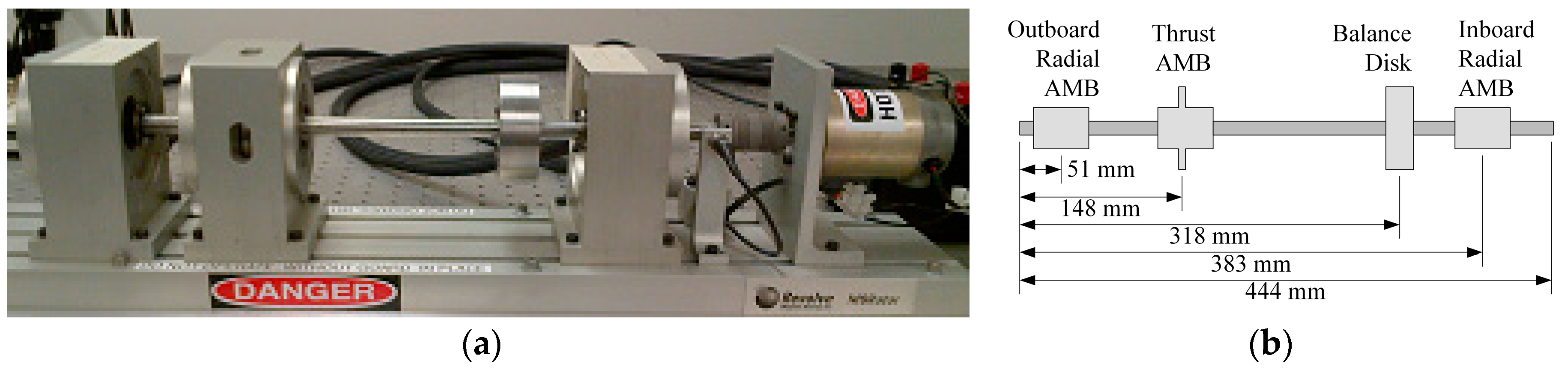
The proposed fault recovery scheme is demonstrated on the experimental AMB test rig shown in
Figure 2. The test rig, manufactured by SKF Magnetic Bearings (Calgary, AB, Canada), consists of a rotor supported on two radial AMBs and one thrust AMB. The rotor is driven by a DC electric motor via a flexible coupling. There is one disk between the bearings and each AMB has a target rotor. The target rotors are of material and appropriately sized optimize the magnetic force from the AMB stator coils. The TD bearings are rolling element type and are situated on the shaft directly outside of each radial AMB target rotor. The TD bearing radial clearance is 190 µm. The shaft is steel and has a diameter of 16 mm.
The basic parameters of the AMB system are listed in
Table 1. The values of current stiffness and position stiffness are resulting from the linearization of the AMB magnetic force at the operating point, which is at the center of the AMB with 1.25 A bias current. Both inboard and outboard AMBs are of the same type and have the same parameters. The rotordynamic values of the components on the shaft are listed in
Table 2. These components are affixed to the shaft with collets.
The rotor is modeled with the FE method using 32 Timoshenko beam elements. Each collet affixed rotor component is accounted for with a lumped mass occurring at a FE node placed at its center of mass. FE nodes are also placed at the AMB force and sensor locations for typical assembly of the open-loop plant model. FE nodes are also placed at the TD bearing locations for fault recovery controller synthesis. The FE model is reduced through modal truncation, retaining two rigid body modes and two flexible modes and neglecting higher order modes.
The open-loop plant is assembled including the FE rotor model, linear AMB model, and pulse width modulation amplifier model, which includes digital phase lag and AMB slew rate. The open-loop model is confirmed against experimental system identification data.
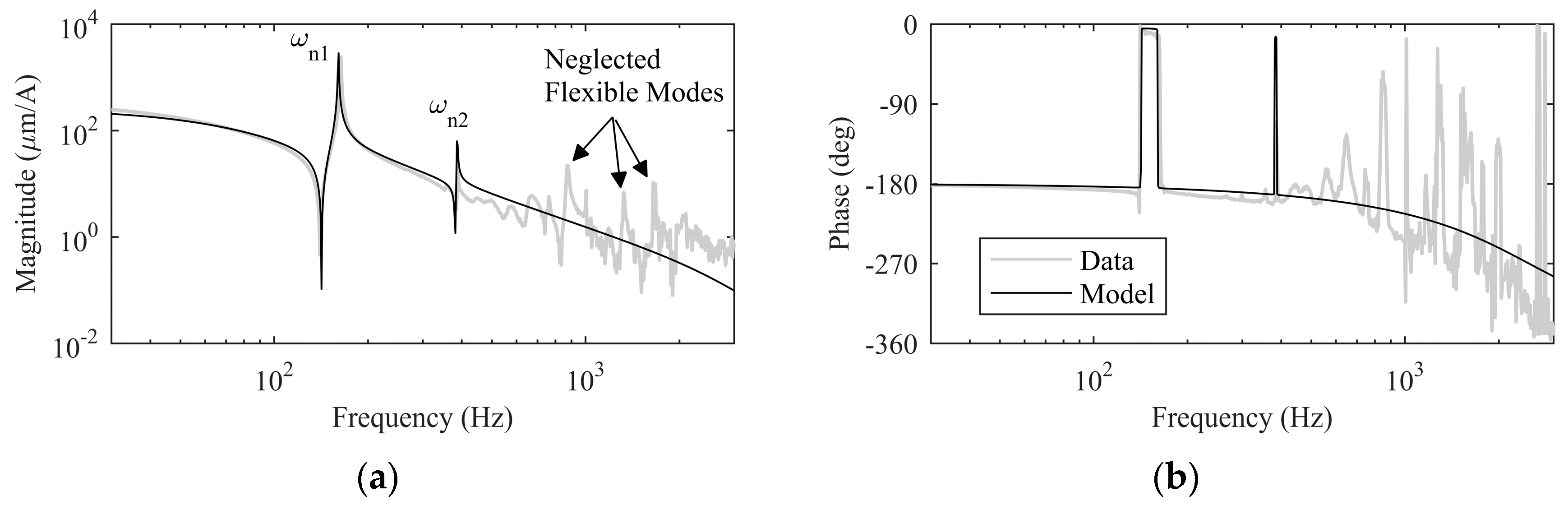
Figure 3 shows the Bode plot of the open-loop model from control current input to position sensor output. The model is 4-input 4-output for each radial AMB axis and assumes the thrust axis is dynamically decoupled from the radial axes. The figure shows a single characteristic radial control axis of the roughly symmetric system.
Figure 3 also shows the results of experimental sine-sweep from the same input and output. The open-loop AMB system, including the bias current, which effects the position and current stiffnesses, is inherently unstable. To perform the experimental sine sweep, a stabilizing AMB control (PID) is used and input perturbation is superimposed on the closed-loop control current. Then, the open-loop frequency response is extracted from the total current and position response data. The comparison shows agreement between the model and experimental system, which is a critical prerequisite for model-based controller design. The first two rotor flexible modes are indicated by peaks in the magnitude at 164 Hz and 387 Hz,
ωn1 and
ωn2, respectively. Higher frequency flexible modes, which are neglected in the model, can also be seen in the figure. Excitation of these modes by the AMB controller is avoided by controller roll-off, which is achieved through performance weighting, as detailed in
Section 2.4. More detail on the mathematical modeling and system identification of the AMB test rig can be found in the earlier study [
19].
2.3. Contact Force Estimation and Performance Weight
The worst case TD bearing force on the rotor when running on the TD bearings must be bounded in order to synthesize the recovery controller, which is required to be robust to that disturbance. A simulation is performed in order to estimate those forces. A simplistic TD bearing model is used in the simulation, which is then tuned to match experimental time response data.
The experimental rotor is levitated and run at 2000 RPM. The current to the AMB coils is abruptly turned off and the rotor is allowed to fall freely onto the TD bearings while the motor is still driving rotation.
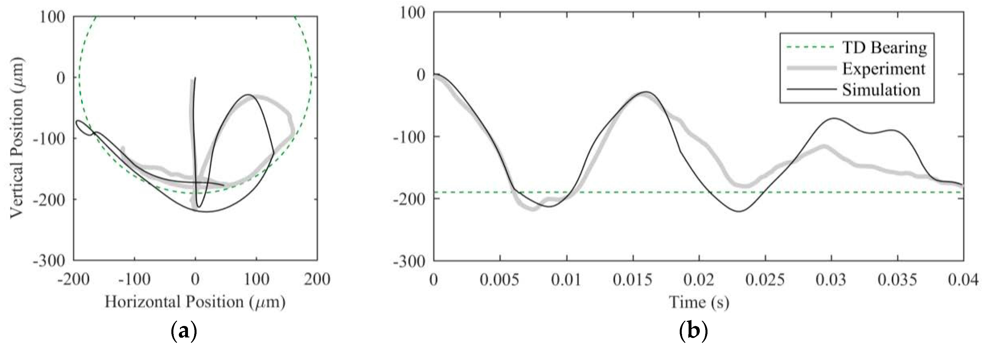
Figure 4 shows the orbit response and time response from the outboard AMB sensor after the AMB support is removed. The rotor starts at 0 µm, the center of the AMB. The rotor then falls in the negative vertical direction until it hits the TD bearing which is shown as the dashed line in the figure. The position signal goes outside of the TD bearing clearance due to a combination of TD bearing deflection and bending of the flexible rotor between the non-collocated TD bearing and sensor. The rotor bounces up and to the right due to the stiffness of the TD bearing and initial relative velocity between the TD bearing and rotor surface, which is rotating clockwise. After the initial bounce, the rotor rolls back and forth on the bottom of the TD bearing, driven by the motor and residual unbalance.
The numerical simulation of the rotor drop test is performed in MATLAB™ via
ode45. The same FE rotor model constructed and experimentally confirmed for controller design is used for the numerical drop simulation. The initial conditions are at rest (although subject to the gyroscopic effect) on the AMB centerline. No AMB force or controller is needed for the simulation as these have been deactivated by the simulation start time. Rotor weight and an unbalance force at 2000 RPM are applied. A static unbalance is assumed to be distributed to the AMB force centers, the magnitude of which was originally tuned to rotor orbits in [
19]. Initially, the TD bearing is modeled as a linear stiffness and damping on the FE rotor at the TD bearing nodes with a discontinuity to reflect if the rotor is in contact. It is found that such a simple TD bearing model is not able to explain the first rotor bounce but can return a reasonable response on subsequent bounces. Therefore, it is further assumed that the first bounce is affected by the initial relative velocity between the rotor surface and TD bearing inner raceway but that, for subsequent contact, the TD bearing has accelerated to a similar velocity as the rotor. The simple TD bearing model is augmented with an exogenous force on the rotor, which occurs immediately prior to first contact. The magnitude and direction of that force are then tuned to match the first experimental bounce.
Figure 4 also shows the responses for the tuned simulated drop test under the same conditions as the experiment. There are obvious disparities between the experiment and simulation, which the authors attribute to the simplicity of the TD bearing model. However, the similar magnitude of the overall response suggests that the simulated TD bearing force is of realistic magnitude. Therefore, the simple simulation is used as a practical solution to estimate the TD bearing force.
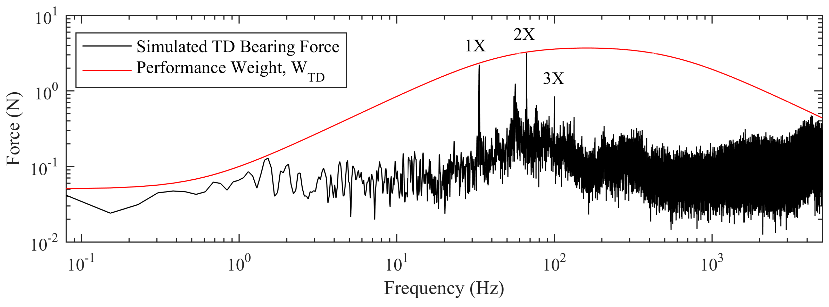
The simple TD bearing model with parameters tuned to the drop experiment is used in a simulation to bound the expected TD bearing force. The simulation includes a rotor drop impact followed by continuous running on the TD bearings for 10 s, during which the rotor is driven by residual unbalance to bounce on the bottom of the TD bearings in a chaotic like fashion. For this time, the TD bearing forces in all four radial axes are collected. The frequency spectrum for the each of the four forces is found using FFT of the sampled numerical data. Then, for each frequency, the largest force from each of the four axes is taken. The result is the frequency spectrum shown in
Figure 5. The apparently noisy result is due to the chaotic like bouncing of the rotor on discontinuous stiffnesses and the frequency-by-frequency combination of the four axes forces. The TD bearing force is dominated by harmonics of the running speed, 1X, 2X, and 3X. The 2X peak also has sidebands at ±10.2 Hz.
Figure 5 also shows the weighting function
WTD.
WTD is crafted manually to have greater magnitude than the simulated worst case TD bearing force at all frequencies below the anticipated Nyquist frequency of the digital controller. Then,
WTD is used to weight the exogenous perturbation input to the FE nodes at the TD bearing locations during controller synthesis. The transfer function of the final TD bearing force weight is presented in the next section on details of the experimental controller design.
2.4. Controller Synthesis for the Experimental System
The parametric uncertainties used for robust AMB controller synthesis are as follows and are summarized in
Table 3. Uncertainties are placed on the two retained natural frequencies of the rotor model. The uncertainty bound is selected to capture any mismatching between the nominal model and experimental system identification shown in
Figure 3. As the FE rotor model is expressed in modal coordinates, the parametric uncertainty is conveniently placed on the square of the natural frequencies. The natural frequency uncertainty is of the complex type for the added benefit of robustness to modeling error of modal damping.
Real uncertainties are placed on the AMB current stiffness and position stiffness. The uncertainties are intended to account for errors due to linearization. The uncertainty bounds are taken from [
19] and found to yield good effective control. The uncertainty on position stiffness is relatively large because position stiffness is the destabilizing term in a linearized AMB system. Also, real uncertainty is placed on running speed, which appears in the gyroscopic effect in the rotor model. The nominal running speed is set at 1000 RPM and a ±100% uncertainty covers the speed range from start up to target speed of 2000 RPM. This running speed is relatively low compared to most AMB applications. The test rig is modular and manually configured without special balancing, making higher speeds not convenient. However, the low speed demonstration is found to be sufficient to show the efficacy of the proposed control method. Higher speeds are expected to make TD bearing forces, and therefore the need for a recovery controller, greater.
Each natural frequency uncertainty perturbation appears twice, once for each perpendicular rotor plane. The running speed uncertainty appears 6 times because the gyroscopic effect effects the two retained bending modes and the second rigid body mode, all in two perpendicular planes. The current and position stiffness uncertainties are assumed to be the same in all radial AMB axes. A more conservative approach would be to allow all radial AMB axes to vary independently; however, the present assumption provides a more tractable problem for μ-synthesis and is found to yield good results.
The performance weights used for controller synthesis for the test rig are shown in
Table 4. These weighting transfer functions are equally applied to each of the four radial AMB axes. The weights on sensor noise, external load, and control current limit are common to both performance and recovery controllers. The allowable rotor position, however, differs in that the performance controller is required to hold the rotor close to the center of the bearing whereas the recovery controller my allow deflection up to the TD bearing clearance. Also, the recovery controller is required to tolerate the TD bearing force as discussed in the previous subsection.
3. Results
In this section, the results of controller synthesis for the test rig and parameters discussed in the previous section are presented. Then, the results for a fault recovery experiment using the recovery controller and the performance controller are presented.
3.1. Results of Controller Synthesis
μ-synthesis is performed on the two uncertain and weighted plant models using the MATLAB™ Robust Control Toolbox to perform the D-K iterations. The performance controller results from 2 D-K iterations, achieving a μ-value of 0.89. The recovery controller results from 2 D-K iterations, achieving a μ-value of 0.96. Therefore, each controller is expected to yield robust stability and robust performance for their corresponding operation regiments.
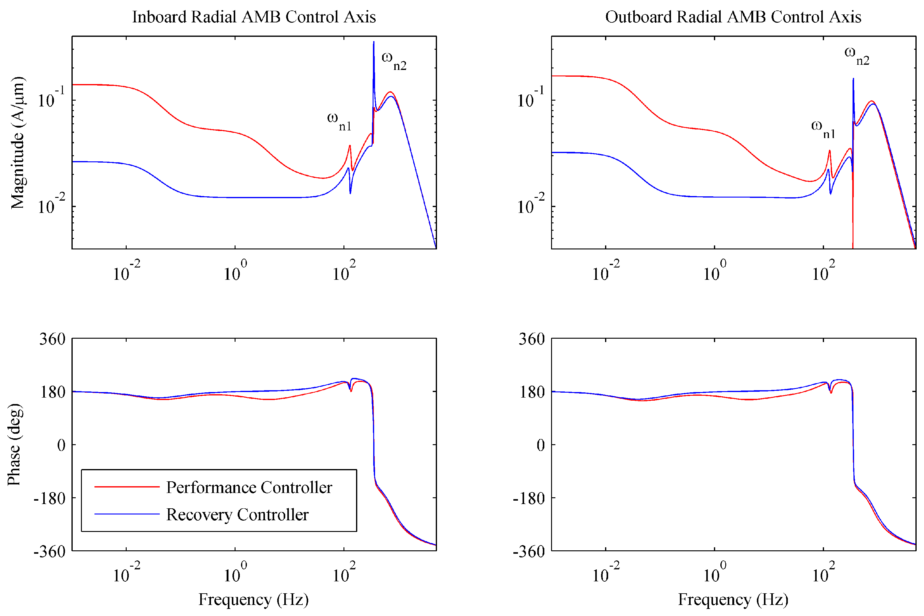
Each controller is 4-input 4-output for each radial AMB axis. The Bode plots of two I/O pairs on the main diagonal are shown in
Figure 6. This figure is for one axis on the inboard AMB and one axis on the outboard AMB in the same plane. The controllers are similar due to the approximate symmetry of the rotor. Those transfer functions for the perpendicular plane are also similar due to the rotor being axisymmetric. These are on the main diagonal of the 4 input 4 output controllers; the off diagonal transfer functions follow similar trends but are at least one order of magnitude lower.
Both performance and recovery controllers exhibit negative feedback for stabilization of the AMBs. Both have features for control of the rotor flexible modes at ωn1 and ωn2 before rolling off at high frequency. The recovery controller has a significantly lower low frequency gain, which prevents high control currents when the rotor is at large deflections such as would occur during loss of levitation. The recovery controller also has lower gain at the first rotor flexible mode but higher for the second. The performance control is 40th order, whereas the recovery control is 48th order due to the additional states in the plant model for the TD bearing weight.
The μ-synthesized controllers are fairly high order. For digital implementation, they are both reduced to the 36th order and discretized at 20 kHz with ZOH via MATLAB reduce and c2d, respectively. Then, the discrete controllers are put in canonical state-space form for optimization of real time calculations via MATLAB canon. The controller implementation is executed with a dSPACE1103 rapid control prototyping board, which is laboratory grade equipment. For industrial implementation, further reduction of the weighted plant model or the synthesized controller may be required for practical implementation.
3.2. Results of Controller Implementation
It is anticipated that the performance controller may have difficulty relevitating a delevitated rotor at running speed. It is also anticipated that the recovery controller will yield low bearing static stiffness and therefore poor steady-state support. Therefore, a switching scheme is utilized for implementation of the recovery controller [
4]. In AMB systems, for safety reasons, it is common to set a deflection limit at which power is removed from the AMBs and motor, in order to prevent the loss of stability. In the event that an acute external fault causes violation of this safety limit, an attempt is made to safely power down the system before relevitation. The proposed scheme for implementing the recovery controller utilizes a similar safety limit; however, if that limit is violated the AMB automatically switches to the recovery controller instead of powering down. The recovery controller can return the rotor to within the safety limit after the external fault has passed. Then, after a prescribed amount of time within the safety limit, the AMB automatically switches back to the performance controller.
To test the proposed recovery controller and switching scheme, an experiment is conducted. The test rig is levitated and rotated at the nominal controller design speed, 1000 RPM. When steady state is reached, current to the AMB coils is abruptly stopped to mimic a power failure. The rotor is allowed to fall onto the TD bearings. After approximately 2 s running on the TD bearings, the current is restored and the rotor relevitates while still rotating.
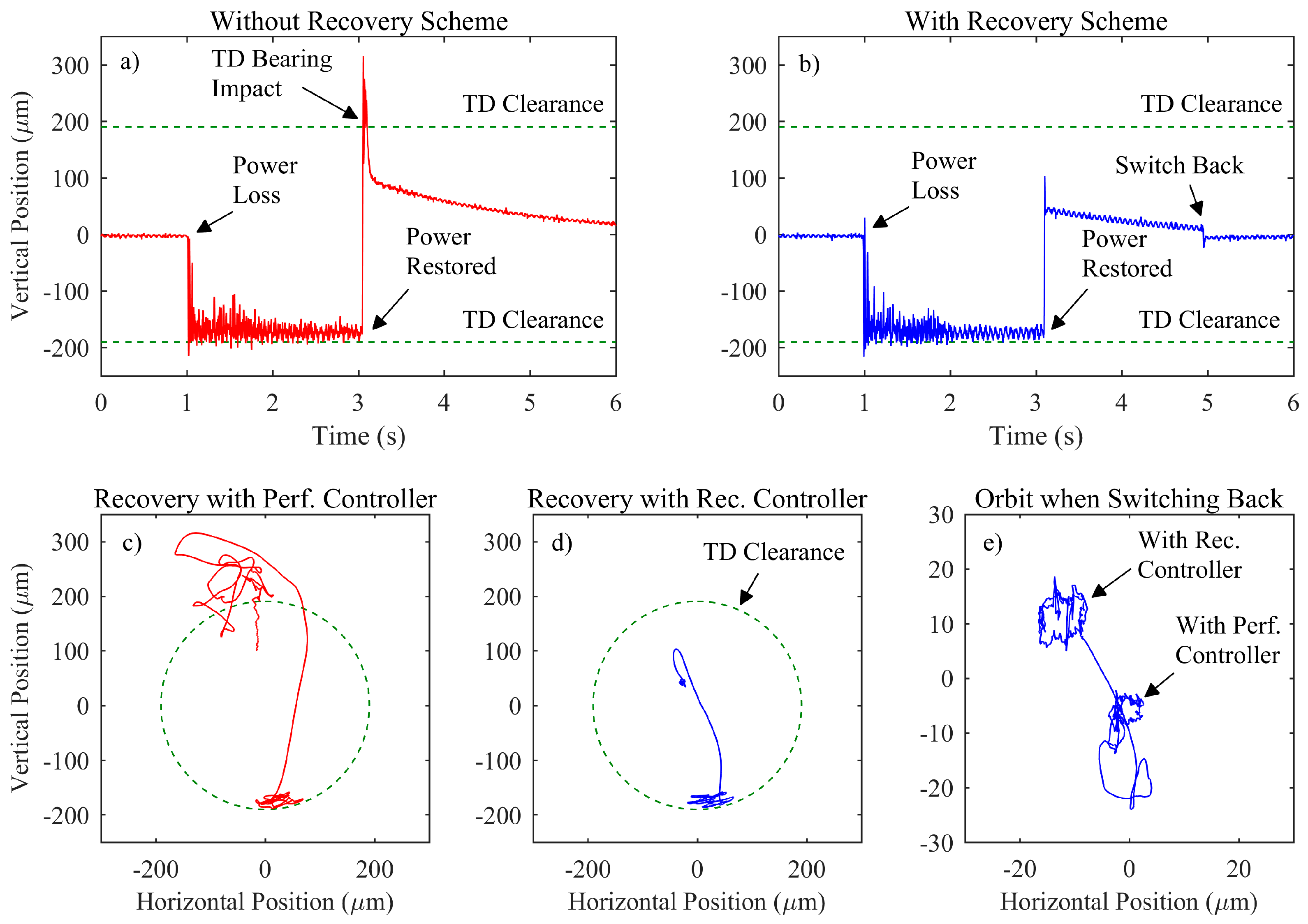
Figure 7 shows the time history of the levitation failure and recovery test when using (
Figure 7a,c) just the performance controller and (
Figure 7b,d,e) the proposed recovery controller and switching scheme.
In each case, the rotor starts at 0 µm, corresponding to the center of the AMB. At 1 s, the current to the AMB coils is stopped. The AMBs in the recovery scheme trial are automatically switched from the performance controller to the recovery controller when the sensor signal surpasses the predefined safety limit of ±100 µm (although current is still not supplied to the coils). For both cases, from approximately 1 s to 3 s, the rotor runs supported loosely by the TD bearings, resulting in a chaotic bouncing/rolling motion. At approximately 3 s, power is restored. The system with no recovery scheme responds violently with overshoot, causing impact with the top of the TD bearing, but it is ultimately able to return to stable levitation. The system with the recovery controller returns to stable levitation quickly with little unwanted dynamics. After approximately 2 s inside the ±100 µm safety limit, the AMBs automatically switch back to the performance controller.
Plots of
Figure 7c,d show the orbits during relevitation with the performance controller and the recovery controller, respectively. The TD bearing radial clearance is indicated with the dashed line. The orbit plot including horizontal and vertical response better shows the violent overshoot when attempting relevitation with the performance controller and the possibility of developing into a contact mode. Plot of
Figure 7e shows the orbit of the recovery scheme trial when switching from the recovery controller back to the performance controller. Smaller orbit size and less overall deflection from the AMB center indicates superior performance of the performance controller when inside the proper operating region.
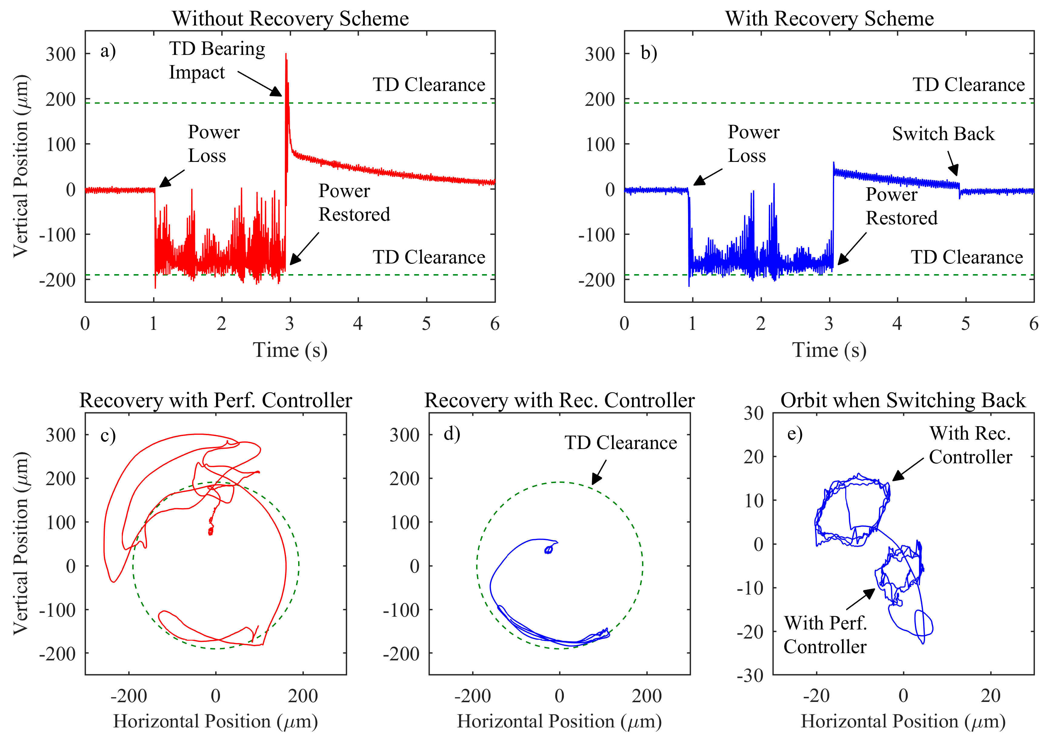
The power loss and recovery test is repeated at the maximum controller design speed of 2000 RPM. The results are shown in
Figure 8 in the same format as
Figure 7. The higher speed exacerbates the problems with levitation recovery while rotating.
The time response and orbit when relevitating with the performance controller show an even more violent transient. However, the proposed control method is still able to cope with the higher speed and achieves levitation recovery without unwanted dynamics. These results demonstrate the efficacy of the proposed method.
4. Discussion and Conclusion
An AMB control method for recovering levitation of a rotor that has been temporarily delevitated by an external fault has been proposed. The proposed method uses μ-synthesis to design an AMB controller, which is robust to very large rotor deflections and TD bearing forces on the rotor. The resulting recovery controller exhibited lower static gains to prevent current saturation during relevitation while maintaining high frequency dynamics to control the rotor flexible modes. The recovery controller is automatically activated if rotor delevitation is detected. The proposed levitation recovery method was demonstrated on an AMB test rig. The rig was run at 1000 and 2000 RPM, and the current to the magnetic coils was temporarily stopped to cause an external fault. After the rotor was running on the TD bearings, the power was restored. The trials using a baseline AMB controller responded violently, hitting the top of the TD bearing before recovering levitation. The trial using the proposed recovery controller was able to recover levitation quickly with no unwanted dynamics.
These developments advance the current state-of-the-art by making the overall AMB-system more reliable. The assurance of levitation recovery will lead to increased acceptance of AMBs in industry at large. Therefore, AMBs will become more widespread and the already proven advantages of AMBs, e.g., higher efficiency and longer life, will more benefit society.
A deficiency in this work is the simplistic model used to estimate a bound on the TD bearing force used for controller design. Therefore, a direction of further research would be to apply this controller design method using a more sophisticated TD bearing model. Alternatively, experimentally gathered TD bearing force data may be used to make the performance bound. Also, the test of a typical PID controller, which has been designed following the frequency response trends found effective with the recovery controller, would be interesting and may prove more useful for industrial application.


