Article

Applying Standard Industrial Components for Active Magnetic Bearings

Siemens AG, Nonnendammallee 72, 13629 Berlin, Germany
*
Author to whom correspondence should be addressed.
Actuators 2017, 6(1), 8; https://doi.org/10.3390/act6010008
Submission received: 30 November 2016 / Revised: 6 January 2017 / Accepted: 25 January 2017 / Published: 4 February 2017
(This article belongs to the Special Issue Active Magnetic Bearing Actuators)

Abstract

:
With the increasing number of active magnetic bearing applications, satisfying additional requirements is becoming increasingly more important. As for every technology, moving away from being a niche product and achieving a higher level of maturity, these requirements relate to robustness, reliability, availability, safety, security, traceability, certification, handling, flexibility, reporting, costs, and delivery times. Employing standard industrial components, such as those from flexible modular motion control drive systems, is an approach that allows these requirements to be satisfied while achieving rapid technological innovation. In this article, we discuss technical and non-technical aspects of using standard industrial components in magnetic bearing applications.

Graphical Abstract

1. Introduction

Active magnetic bearings (AMB) have been used in industrial and research environments for many years. Starting from small applications some decades ago, they are now used to levitate light and heavy rotors in applications ranging from the oil and gas industry, chemical industry, energy industry, and up to applications in the field of environmental protection (e.g., [1,2,3,4,5]). Their advantages include their low maintenance costs, high level of cleanliness and safety due to the absence of oil, high availability, as well as their operational advantages such as high speed without the need for a gearbox or continuous speed ranges from standstill to maximum speed. This is true even for machines with bending modes within the operational speed range.
The use of active magnetic bearings in other industrial areas—including high power applications—increases the need to fulfill requirements such as robustness and reliability, safety and security, flexibility, compliance with international standards, and lower operating costs. Industrial components are designed to precisely address these types of use cases. High production numbers imply adequate quality assurance measures that guarantee a maturity level to fully comply with the requirements of industrial applications.
In general, we consider components as standard industrial components if their life cycle—in particular the requirement specification phase, development, test, operation, and market response management—is realized according to defined processes and quality assurance standards. In addition, we assume that the number of units sold is high so that failure rates can be statistically analyzed with a high level of confidence.
In this article, we discuss several aspects of using standard industrial components for active magnetic bearings in large machine applications, as reported in [6,7]. We explain why using standard industrial components is beneficial when it comes to fulfilling the requirements of applications in industrial environments from a technical point of view, while carefully considering the total cost of ownership.

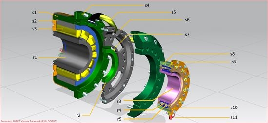
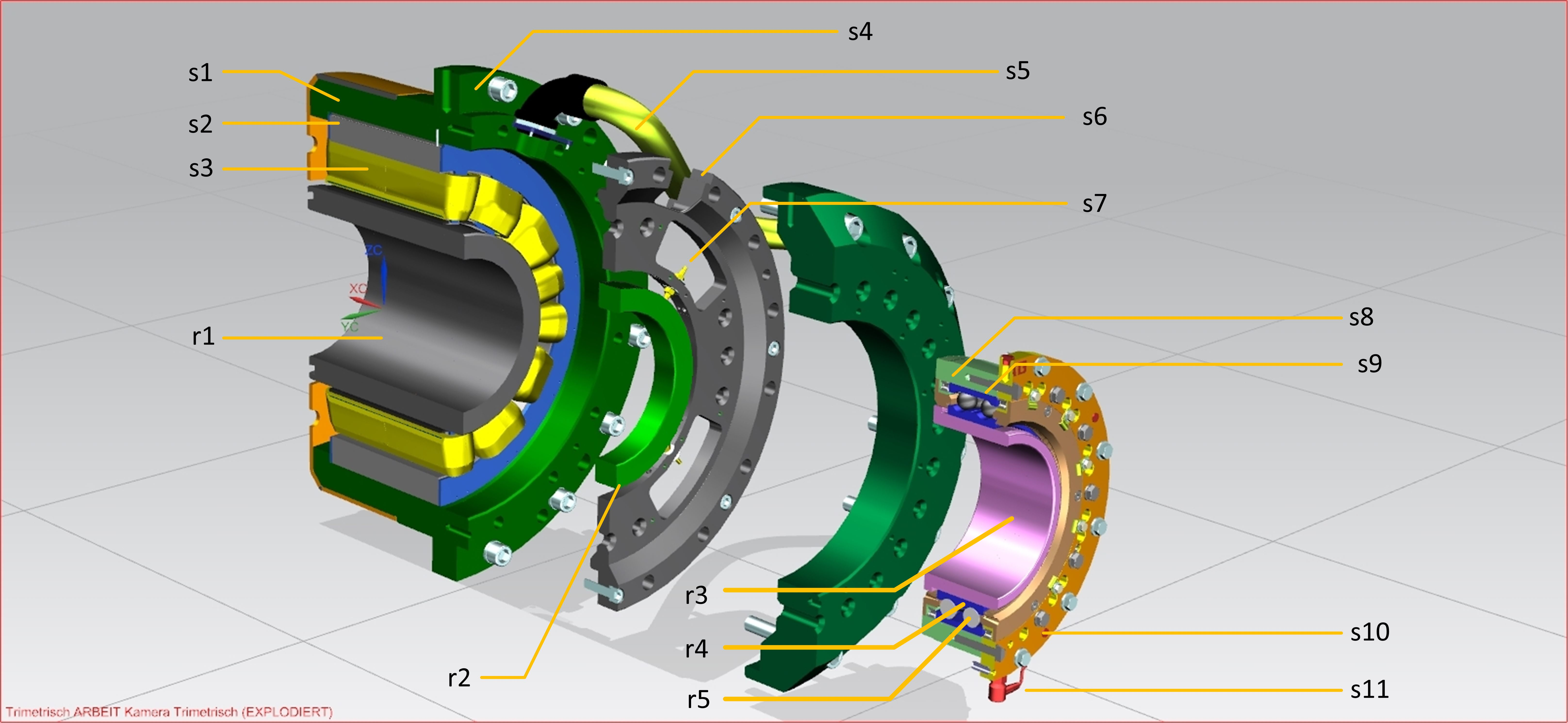
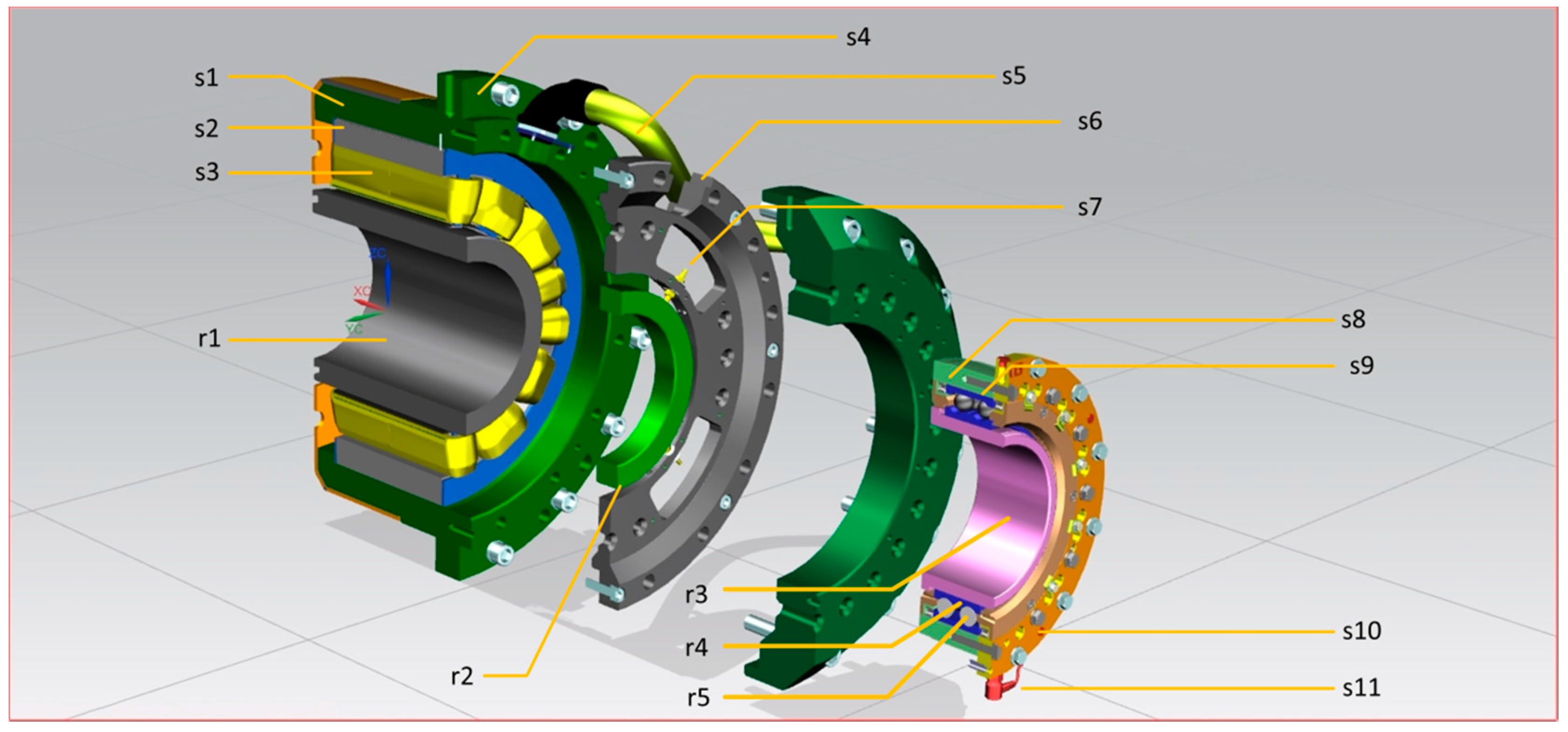
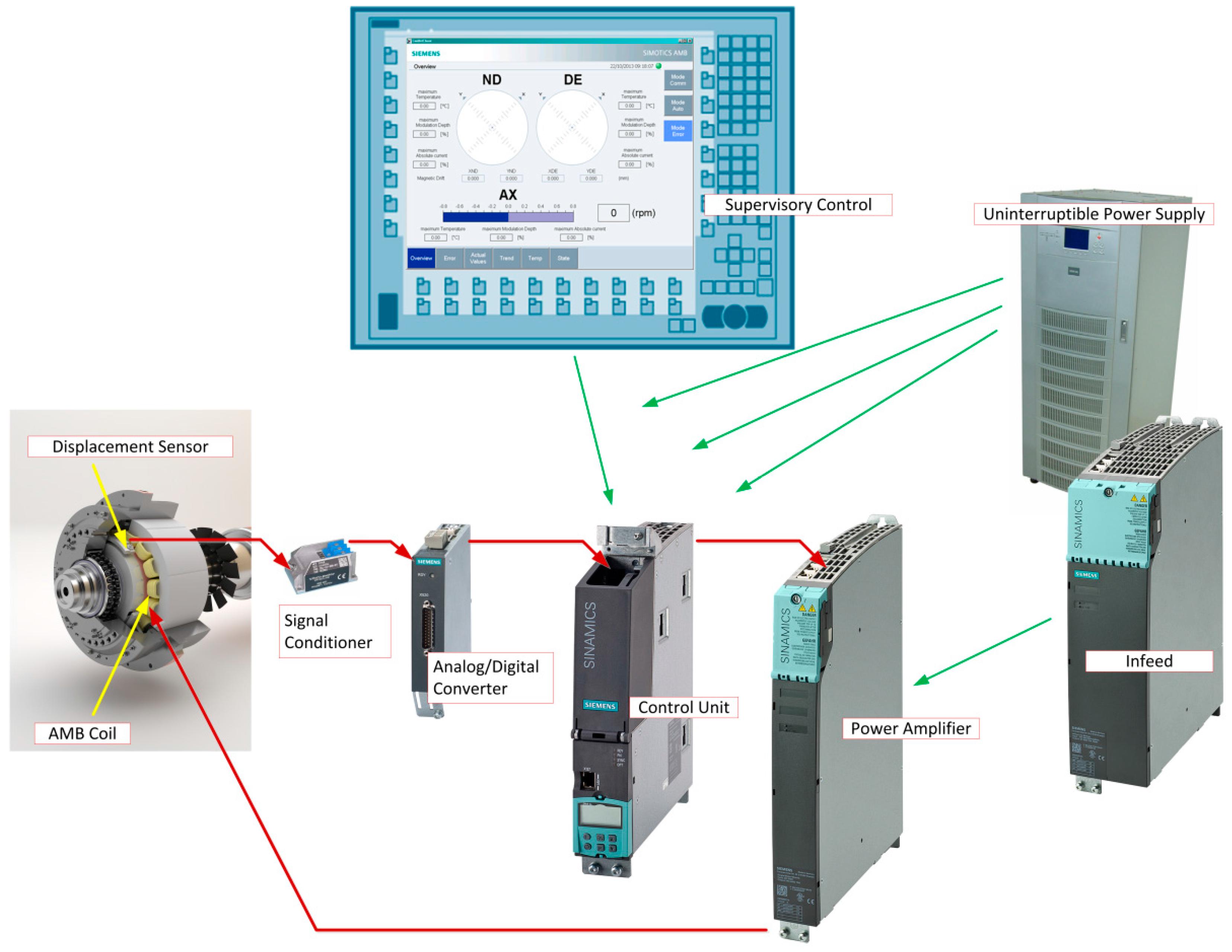
2. The Active Magnetic Bearing System and Its Components

Active magnetic bearings consist of mechanical and electronic parts. An overview of the mechanical parts is shown in Figure 1. Since the number of magnetic bearing mechanical parts sold is usually not very high, it is not permissible to consider them as standard industrial components. This does not mean that the knowledge gained from production processes for high volumes is not leveraged. This is particularly true, since the bearing stator largely resembles the stator of an electrical motor, which means that it is possible to use identical standards and manufacturing tools and processes.
In contrast to the mechanical parts, for the electronic components, standard industrial components produced in high unit quantities can be optionally used. An overview of the major electronic components as they are used in Simotics AMB-Technology is shown in Figure 2 [8]. Many thousands of these components are manufactured and sold every year.

3. The Advantages of Standard Industrial Components

In general, customers require active magnetic bearings that provide continuous service (i.e., a high availability and reliability). Further, not only must the initial investment costs be able to be predicted, but also the total cost of ownership. Active magnetic bearings that are based on standard industrial components allow for an accurate prediction of costs due to the following properties:
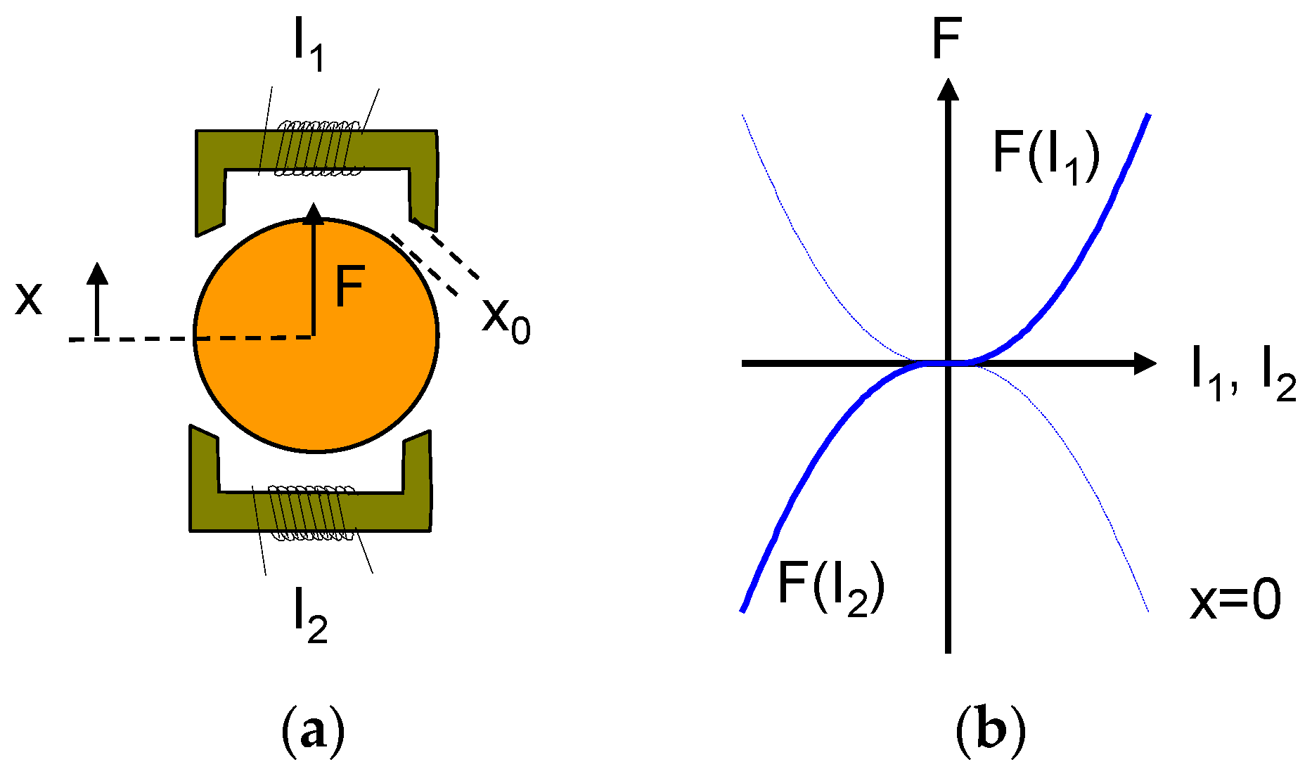
  • Robustness: Robustness refers to the ability to tolerate deviations from the actual design point. Examples of such deviations are deviations in the mechanical dimensions of the machine parts, assembly and mounting inaccuracies, or deviations in the thermal properties of the machine or the AMBs. The robustness of a magnetic bearing largely depends on the air gap between the AMB rotor and stator. A large air gap is beneficial during assembly and alignment of the machine, and in the event of an unplanned landing into the back-up bearings [5]. A sufficiently large air gap prevents the AMB rotor and stator from coming into contact with one another, which may occur due to rotor bending and deflections in exceptional loading situations. In addition to the possible unplanned events, a large air gap is necessary to be able to tolerate the thermal expansion of the AMB rotor diameter when operating at full load/high temperatures. As a consequence, defining the required air gap is a critical issue when designing a magnetic bearing, and needs to be based on detailed calculations and/or simulations. However, a large air gap requires high currents in order to keep the magnetic field at the required level. Modular motion control drive systems comprise a family of power amplifiers up to high power ratings, which provide maximum flexibility with respect to the configuration of the AMB control system. A fully scalable AMB control system ensures that the actual power requirements can be fully complied with.
  • Availability: Availability is the probability of functioning at any given instant [9]. It can be estimated from the ratio of the average uptime to the sum of the average uptime and average downtime of a plant. The averages of uptime and downtime can be expressed in terms of mean time between failure (MTBF) and mean time to repair (MTTR), respectively. Industrial electronic components manufactured in large numbers are usually continuously optimized with respect to availability. Furthermore, due to the large statistical basis, there are reliable values available for the MTBF. These numbers allow the availability of the components to be estimated so that maintenance intervals and service tasks can be planned. In turn, the risk of AMB failure can be minimized, therefore minimizing unscheduled maintenance costs.
  • Reliability: “Reliability is the probability of functioning properly over a given period” [9], or, as defined in [10], the probability of providing a specified performance level for a specified duration in a specified environment. There is no unique way of quantifying reliability; some definitions involve the accumulated rate of failure, the failure intensity, the MTBF, and the survival rate [10].
  • Safety and functional safety: According to [9], safety is the absence of unacceptable risk. In general, when designing and operating a plant, it is required to perform risk assessments and to reduce the residual risk to an acceptable level by applying appropriate measures (e.g., by using inherently safe designs or by applying safety-related electronic components). Functional safety refers to the safety of the equipment and the control equipment, depending on the correct operation of the electrical/electronic/programmable electronic (E/E/PE) safety-related systems and other risk reduction measures [9]. Standard industrial components are thoroughly developed and tested according to standardized development and quality assurance processes before they are launched into the market. In this sense, they inherently have a low risk of failure provided they are operated within their specified operating range. In addition, industrial component families may include specifically designed (SIL certified) components which are used for monitoring, and which take the appropriate action in the case of failure to bring the whole system into a safe state. SIL-certified components can recognize their own failure and bring the plant—even in such a case—into a safe state. The advantage of using SIL-certified industrial components from the same electronics supplier is that these components can be seamlessly integrated into the overall AMB control concept.
  • Security: For the configuration of a magnetic bearing control system, for monitoring, maintenance, and failure diagnostics, it cannot be avoided that this system can be accessed, therefore making it vulnerable to cyber-attacks. As a consequence, there is a strong demand for a secure, efficient, and comfortable access concept with roles, permissions according to access-levels, and security policies, as well as know-how protection, which allows full design flexibility so that an IT security concept can be fully integrated into an existing IT infrastructure. Such an overall concept allows an AMB control system to be accessed for monitoring, diagnostics, system control, and other service-related tasks—even remotely.
  • Traceability: When developing and manufacturing standard industrial components, standardized processes must be strictly complied with. These processes have been put in place to fulfill the required quality issues, but also legal regulations. Traceability ensures that the composition of a product can always be traced, along with the processes, machines, etc. that have been involved in the manufacturing. In the case of a problem, it is therefore possible to retrace all manufacturing steps. This is a crucial prerequisite in conducting a root cause analysis and for initiating remedial action. Traceability requires a clearly structured development and manufacturing process, and hence inherently leads to an improvement of the product quality. Traceability involves strict tracking of software versions and hardware revisions—including design drawings and calculations.
  • Certification: Standard industrial components are by default delivered with the certificates documenting important properties required by legislation, customers, or the applicable standards (e.g., [11]). Examples are certificates for explosion protection and electromagnetic compatibility. The required overall plant certification can be easily performed based on these documents.
  • Handling: For manufacturing, commissioning, and operation, it is necessary to have a variety of interfaces that allow intuitive use and easy operation. Connectors should allow quick commissioning and for components to be quickly replaced in the case of service and maintenance. Standardized components provide debugging interfaces, which are useful during development and fault diagnostics. Standard industrial components are provided with thoroughly designed and tested engineering software, allowing the necessary parameters and system information to be fully accessed.
  • Flexibility: Standard components can be combined and configured so that they can be adapted to address the needs of the application. In general, they provide several types of interfaces that allow additional devices and measurement equipment to be connected. Examples include Profibus, Profinet, Ethernet, analog/digital converters, and electrical input/output ports. Furthermore, standard industrial components are completely harmonized and coordinated with one another so that they can be combined without additional components (e.g., human–machine interface and process supervision equipment). Very often, changes can be simply made by adjusting configuration settings using the system’s engineering software. Employing standard components means that there are a high number of service engineers that are familiar with them.
  • Reporting and condition monitoring: Analyzing process and machine data is becoming increasingly important. Standard components allow all of the relevant machine and process data to be accessed, and provide options for transferring and storing this kind of information. As a consequence, they support the application of modern techniques and frameworks such as big data for process and machine improvements.
  • Costs: Since the development costs are distributed over a large number of units, the advantages of industrial standard components can be made available at a fraction of the cost of non-standard components. Further, spare parts can be simply managed using standardized lifecycle management systems.
  • Delivery times: Since these electronic components are manufactured in large numbers, they are generally available off-the-shelf, thus keeping delivery times low. Spare parts that are required can often be ordered locally. The lifecycle management system guarantees that spare parts are available over a long period of time.

4. Using Standard Industrial Components

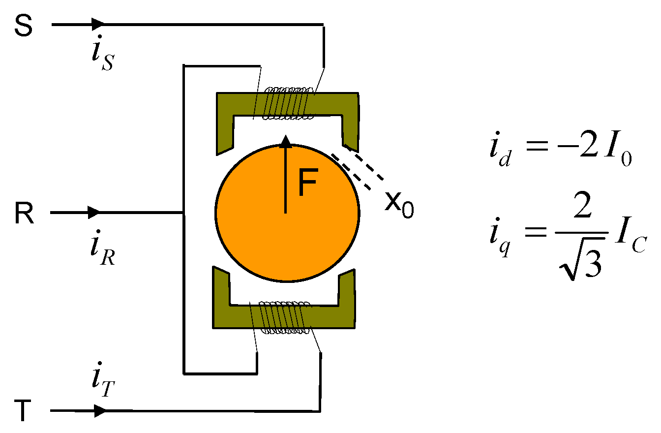
4.1. Example: Application of Standard Three-Phase Inverters for AMB Operation

Industrial three-phase inverters for motor applications are produced in very large unit quantities, and are available with high control sampling rates for high-end applications such as motion control and robotics. Many vendors have different power ratings in their portfolio so that they can provide solutions for a wide range of machine sizes. A lot of effort is taken to continuously improve the reliability of the inverter hardware and firmware. This technology can be applied to operate the axes of magnetic bearings. The following describes how a single three-phase inverter—as typically used in motion control applications with field-oriented control—can be adapted to address magnetic bearing applications with minimum software changes.
There are typically two electromagnets in one bearing axis. These electromagnets exert forces on the rotor as required in the positive and negative axis directions. As shown in Figure 3, a straightforward strategy to operate the two coils would be to supply the upper coil with current if the rotor needs to be pulled in the positive x-direction, and to supply the lower coil with current if the rotor needs to be pulled in the opposite direction. However, there is a square law relationship between the current and force of an electromagnet. This non-linear relationship between current and force is a problem for a linear controller.
To achieve an approximately linear current/force relationship, a constant bias current I0 is conventionally applied to both coils. To exert a positive force on the rotor, current I1 in the upper coil is increased by the control current IC while the current in the lower coil I2 is decreased by current IC, and vice versa for negative forces. As a consequence, two quadratic functions are added, which results in the linear current-to-force relationship shown in red in Figure 4 when the rotor is at its setpoint position x = 0:
F = k ( I 0 + I C x 0 x ) 2 k ( I 0 I C x 0 + x ) 2 | x = 0 = k x 0 2 4 I 0 K I I C
where k is a constant and x0 is the nominal air gap in the magnetic bearing. KI is the force per control current constant of the bearing.
However, two two-phase inverters are required to operate a magnetic bearing axis, as unequal currents are required in the upper and lower coils. Industrial three-phase inverters for motor applications can drive a current in three phases. Needless to say, two three-phase inverters could be used to realize the conventional control strategy shown in Figure 4. However, one phase in each inverter would remain unused, and the hardware would not be used to its full capability. To avoid this, a method was created to allow a complete magnetic bearing axis to be operated with a single three-phase inverter. This is achieved by simply modifying the drive software.
The basis for this method is the field-oriented control for three-phase motors implemented as standard in the drive software. Field-oriented control for three-phase motors relies on the Clarke–Park transformation [12], which depends on the actual angular position of the rotor, and relates the torque current iq and the flux current id to the phase currents iR, iS, and iT. The current id is only required in motor applications in the case of field weakening, and is usually controlled to a value of zero. Current iq is proportional to the force/torque delivered by the motor. The Clarke–Park transformation allows the flux current id to be independently controlled from torque current iq for arbitrary rotor positions. For a rotor angle of zero, the Clarke–Park transformation yields
i R = i d = 2 I 0 i S = 1 2 i d + 3 2 i q = I 0 + I C i T = 1 2 i d 3 2 i q = I 0 I C
These equations show that flux current id influences the current in phases S and T in the same way, and torque current iq increases the current in phase S, while it decreases the current in phase T. If the magnetic bearing coils are connected to the inverter as shown in Figure 5, current iS flows through the upper coil and current iT flows through the lower coil. If id is chosen to be id = −2·I0 and iq is chosen to be iq = 2/sqrt(3)·IC, then the complete bearing axis can be operated using just one servo inverter, while the drive software modification is mainly restricted to keeping the rotor angle in the Clarke–Park transformation at a fixed value.

4.2. Example: Evaluation and Implementation of Safety Requirements

International standards such as IEC 61508, IEC 61511, and ISO 12100 [9,13,14] provide information and detailed recommendations for the assessment and implementation of safety requirements for industrial and non-industrial machine applications.
As a result of the risk assessment, there is a classification using several safety integration levels for all of the machines in the entire factory. The requirements are then mapped to safety requirements for the individual components of the equipment and to requirements relating to the structure of the setup, so that the risk for humans and the equipment is reduced to an acceptable minimum. Remaining risks need to be communicated and agreed upon.
Standard components can significantly simplify the configuration of a system setup with an acceptable level of risk. As an example, electronic components that are especially designed to accomplish safety tasks (SIL-certified CPUs) can be easily integrated into the architecture. These components can be equipped with redundant communication channels, special self-diagnostic and self-test routines, and safety blocks that are especially certified for these types of applications. These SIL-certified components are used to monitor critical signals and make decisions which, in case of problematic situations, bring the plant into a safe state.
An example of a safety-critical decision is to stop the drive train in a controlled way and then subsequently delevitate the rotor into the backup bearings in case of an instability of the control loop. This instability can be due to significant changes in the rotor dynamics (e.g., loss of a compressor blade).

4.3. Example: Flexibility by Using Standard Industrial Components

Flexibility is particularly beneficial if the costs and technical requirements need to be balanced. For example, different rotor weights, process forces, and safety margins require different power amplifier ratings. In this case, it is advantageous if there is, for example, a selection of different power amplifiers belonging to the same product family that are able to supply the required currents, while keeping the costs at an adequate level. Using the amplifiers from the same family reduces configuring costs to a minimum.
In general, a family of standard industrial components comprises not just power amplifiers, but also control units, SIL-certified CPUs, peripheral components such as sensors, DC link modules, and connectors. It is then very easy to configure a different combination to address a specific customer’s requirements—in fact, it may just require a few changes to the software configuration. In this sense, integrating a redundant measurement path, for example, is essentially a matter of plug-and-play.
Particularly useful is the flexibility of configurable human–machine interfaces (HMIs), where at least labels or the language need to be changed according to customer requirements. A standard configurable HMI means that this can be quickly and efficiently implemented.

5. Discussion

The advantages of using industrial standard components have been presented. However, the question arises as to whether there are also associated disadvantages. From our perspective, there are none. However, there are some practical points that need to be discussed:
  • In order to achieve a certain level of robustness and safety, the development cycles are usually longer for standard industrial components. That is, most recent technical developments may not be available within a short time frame. However, for control units in particular, options are available that allow minor additional features such as filtering or diagnostic blocks to be quickly implemented. Relying on the high quality of the component’s software in general, these additional features can be implemented quickly with low costs associated with regression testing.
  • Making a commitment to a certain family of industrial products requires acceptance of its potential limitations and restrictions. Demands from customers that cannot be fulfilled with components from this product family can either not be satisfied, or components from other product families have to be used. An extension of the product family itself is generally a time-consuming process, including all the steps from requirement engineering until the product is finally released. As the desired properties of standard industrial products—as listed in Section 3—require that defined processes are fully complied with, these restrictions are unavoidable and need to be accepted.
  • Using standardized components may, in general, lead to a loss of optimization in comparison to a fully custom design. However, properly selected standard industrial components generally provide a great flexibility such that the performance degradation can be kept small.
The investment costs for a customer application that are linked to standard industrial components are usually less compared to non-standard components with the same level of quality. Maintaining a high quality standard in industrial applications is important, since the total costs of ownership are determined not only by the associated investment, but also by the minimized risk of failure, the maintenance required, and the easy availability of the components and spare parts.

6. Conclusions

It has been shown that standard industrial components offer multiple significant advantages when used to control active magnetic bearings. They enable magnetic bearing technology to increase the overall performance of the system, and in turn, customer acceptance. In particular, the reliability of the technology can be further increased, and the costs of maintenance and service further reduced. As shown in the examples, industrial standard components can be flexibly configured in many instances, therefore allowing market and customer demands to be quickly addressed.

Author Contributions

G.V.M. and B.-U.K. contributed to Section 2 and Section 3. J.D., B.-U.K. and M.L. contributed to Section 4. B.-U.K. compiled the material and wrote the article.

Conflicts of Interest

The authors declare no conflict of interest. The founding sponsors had no role in the design of the study; in the collection, analyses, or interpretation of data; in the writing of the manuscript, and in the decision to publish the results.

References

  1. Hawkins, L. Application of Flywheel Energy Storage Systems as an Industrial Product. In Proceedings of the 15th International Symposium on Magnetic Bearings (ISMB15), Kitakyushu, Japan, 3–6 August 2016.
  2. Gilarranz, J.L.; Dave, M.; Jamison, T.; Festa, M.; Feichtinger, P.; Denk, J. Non-Hermetic, Oil-free Compression Solutions—A Reliable Approach to Reduce Life Cycle Costs for Compressor Applications. In Proceedings of the Abu Dhabi International Petroleum Exhibition and Conference, Abu Dhabi, UAE, 7–10 November 2016.
  3. Aeschlimann, B.; Hubatka, M.; Peter, M.E.; Stettler, R.; Housseini, R. Commissioning of Off-Shore Gas Compressor with 9-Axes Magnetic Bearing System: Controller Design. In Proceedings of the 15th International Symposium on Magnetic Bearings (ISMB15), Kitakyushu, Japan, 3–6 August 2016.
  4. Düsterhaupt, S.; Neumann, H.; Rottenbach, T.; Vanek, C.; Worlitz, F. High Temperature Active Magnetic Bearings in Industrial Steam Turbines. In Proceedings of the 15th International Symposium on Magnetic Bearings (ISMB15), Kitakyushu, Japan, 3–6 August 2016.
  5. Denk, J.; Köhler, B.-U.; Siegl, G.; Siebke, P. Landing Tests with a 6300 rpm, 9t AMB Rotor in Rolling Element Back-up Bearings. In Proceedings of the 14th International Symposium on Magnetic Bearings (ISMB14), Linz, Austria, 11–14 August 2014.
  6. Denk, J. Active Magnetic Bearing Technology running Successfully in Europe's Biggest Onshore Gas Field. OIL GAS Eur. Mag. 2015, 2, 91–92. [Google Scholar]
  7. Isles, J. Oil-free Bearings Demonstrated at Jänschwalde Power Station. Gas Turbine World 2016, 46, 32–36. [Google Scholar]
  8. SIEMENS. SIMOTICS Active Magnetic Bearing Technology. Available online: http://www.siemens.com/global/en/home/products/drives/motors/high-voltage-motors/simotics-active-magnetic-bearing-technology.html (accessed on 14 November 2016).
  9. International Electrotechnical Commission (IEC). International Standard IEC 61508 (Part 1–7): Functional Safety of Electrical/Electronic/Programmable Electronic Safety—Related Systems, 2nd ed.; IEC: Geneva, Switzerland, 2010. [Google Scholar]
  10. International Electrotechnical Commission (IEC). International Standard IEC 62308: Equipment Reliability—Reliability Assessment Methods, 1st ed.; IEC: Geneva, Switzerland, 2006. [Google Scholar]
  11. American Petroleum Institute (API). API Standard 617: Axial and Centrifugal Compressors and Expander-compressors for the Petroleum Chemical and Gas Industry, 7th ed.; API: Washington, DC, USA, 2002. [Google Scholar]
  12. Field Orientated Control of 3-Phase AC-Motors, Literature Number BPRA073, Texas Instruments Europe, February 1998. Available online: http://www.ti.com/general/docs/litabsmultiplefilelist.tsp?literatureNumber=bpra073 (accessed on 14 November 2016).
  13. International Electrotechnical Commission (IEC). International Standard IEC 61511 (Part 1–3): Functional Safety—Safety Instrumented Systems for the Process Industry Sector, 2nd ed.; IEC: Geneva, Switzerland, 2016. [Google Scholar]
  14. International Organization for Standardization (ISO). International Standard ISO 12100:2010(E): Safety of Machinery—General Principles for Design—Risk Assessment and Risk Reduction, 1st ed.; ISO: Geneva, Switzerland, 2010. [Google Scholar]
Figure 1. Components of magnetic bearing rotors and stators (possible configuration). r1: laminated rotor core, r2: sensor target ring, r3: back-up bearing sleeve, r4: back-up bearing inner ring(s), r5: back-up bearing balls; s1: magnetic bearing housing, s2: laminated stator core, s3: stator winding, s4: bearing flange, s5: cable routing, s6: sensor fixation assembly, s7: displacement sensor, s8: back-up bearing housing, s9: back-up bearing outer rings, s10: back-up bearing flange, s11: back-up bearing condition monitoring sensor (acceleration sensor).
Actuators 06 00008 g001
Figure 2. Electronics and power electronics of a magnetic bearing. The major components are: displacement sensors, signal conditioners, analog/digital converters, control units, supervisory control system, power amplifiers, and an infeed. The infeed provides the DC link for the power amplifiers. Furthermore, a standard 400 V industrial uninterruptible power supply (UPS) is used to ensure uninterrupted operation in case of short term power failures.
Actuators 06 00008 g002
Figure 3. Setup requiring a non-linear control strategy: I1 > 0, I2 = 0 for F > 0 and I1 = 0, I2 < 0 for F < 0. (a) Coil arrangement without bias current; (b) Non-linear current-force relationship.
Actuators 06 00008 g003
Figure 4. Conventional control strategy for AMB coils: constant bias current I0 and control current IC. (a) Coil arrangement with bias current; (b) Linear current-force relationship.
Actuators 06 00008 g004
Figure 5. Control strategy with one three-phase inverter provides control current IC and bias current I0.
Actuators 06 00008 g005

