Article

Design and Characterization of In-Plane Piezoelectric Microactuators

1
Microsystems, Actuators and Sensors Group, Universidad de Castilla-La Mancha, 13071, Ciudad Real, Spain
2
Departamento de Matemáticas, ETSII, Universidad de Castilla-La Mancha, 13071, Ciudad Real, Spain
3
Institute of Sensor and Actuator Systems, Vienna University of Technology, 1040, Vienna, Austria
*
Author to whom correspondence should be addressed.
Actuators 2017, 6(2), 19; https://doi.org/10.3390/act6020019
Submission received: 28 February 2017 / Revised: 30 May 2017 / Accepted: 1 June 2017 / Published: 3 June 2017
(This article belongs to the Special Issue MEMS-based Actuators)

Abstract

:
In this paper, two different piezoelectric microactuator designs are studied. The corresponding devices were designed for optimal in-plane displacements and different high flexibilities, proven by electrical and optical characterization. Both actuators presented two dominant vibrational modes in the frequency range below 1 MHz: an out-of-plane bending and an in-plane extensional mode. Nevertheless, the latter mode is the only one that allows the use of the device as a modal in-plane actuator. Finite Element Method (FEM) simulations confirmed that the displacement per applied voltage was superior for the low-stiffness actuator, which was also verified through optical measurements in a quasi-static analysis, obtaining a displacement per volt of 0.22 and 0.13 nm/V for the low-stiffness and high-stiffness actuator, respectively. In addition, electrical measurements were performed using an impedance analyzer which, in combination with the optical characterization in resonance, allowed the determination of the electromechanical and stiffness coefficients. The low-stiffness actuator exhibited a stiffness coefficient of 5 × 10⁴ N/m, thus being more suitable as a modal actuator than the high-stiffness actuator with a stiffness of 2.5 × 10⁵ N/m.

1. Introduction

Creating devices able to operate in the micrometer scale has been part of the scope of vanguard science and technology for many years. Using the same technology that allowed the miniaturization of electronic circuits, it was possible to fabricate the so-called microelectromechanical systems (MEMS): miniaturized systems composed of mechanical structures and electronic components. The microactuators, in particular, have achieved remarkable progress in many fields [1,2], being able to generate forces or displacements to perform scanning, tuning, manipulating, or delivering functions [1,2,3,4]. It was not until the last decades that a large number of actuators have been developed for various applications, usually driven by electrostatic [5], electromagnetic [6], thermal [7], piezoelectric [8], and Lorentz forces [9,10]. The application of piezoelectric microactuators is challenging, since a considerably high driving voltage is needed to attain practical forces or displacements, and thus the real-world application of the actuators is still limited.
Regarding in-plane actuators, the use of PZT (Lead Zirconate Titanate) as a piezoelectric layer has recently shown promising results: laser-machined [11] and thick-film PZT-based actuators [12] in the millimeter size demonstrated displacements of 60 and 12 nm/V, while sub-millimeter-sized thin-film PZT-based actuators reached in-plane displacements as high as 300 nm/V with basic geometries and low stiffness [13,14,15]. Seeking a better integration for silicon-based fabrication protocols, AlN allows for monolithic microdevices to be easily fabricated at the expense of a much lower piezoelectric performance. So, an appropriate design of the actuator is crucial for top performance AlN-based actuators.
The design of piezoelectric microactuators, as smart structures, is mainly focused on two complementary problems: designing the host structure or substrate for a given actuation system or designing the actuation system for a given host structure. In this sense, both the first and the second approach are limited by the given host structure or actuation system, so to achieve better results for a given application, both problems need to be solved simultaneously, using a numerical method capable of distributing host material, actuating material, and voids. Level set methods [16,17] offer versatility, but are difficult to implement and computationally expensive. Numerical methods based on building blocks [18], although fast, are limited to basic geometries, while interval techniques require an analytical model of the host structure [19]. Under certain hypotheses of isotropy and simple geometries, SIMP-based methods (Solid Isotropic Material with Penalisation) [20,21,22,23,24,25] are more suitable. From a practical point of view, SIMP methods are largely used to design piezoelectric in-plane and out-of-plane transducers [25,26,27].
In this work, two different piezoelectric actuator designs were investigated in order to obtain a high efficiency of the actuation and sensing mechanisms, determined by the electromechanical coefficient. The identification of the vibrating modes and the characterization of the static deformation was a fundamental goal. For this reason, the electrically detected modes were optically identified using a speckle pattern-based interferometer, capable of building a map of both the out-of-plane and the in-plane motion of the device surface. In addition, the information on the mechanical displacement amplitude obtained with this equipment allowed us to determine the efficiency of the actuation and sensing mechanisms.

2. Materials and Methods

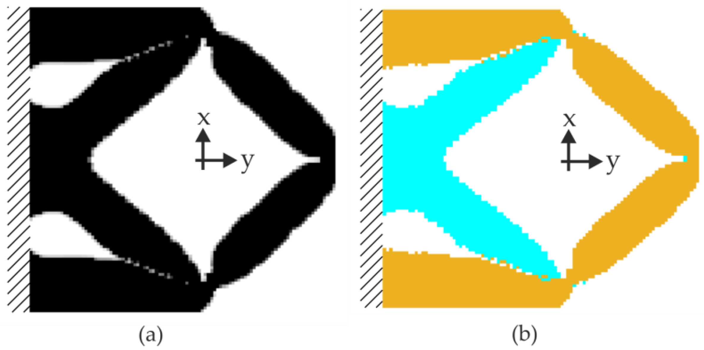
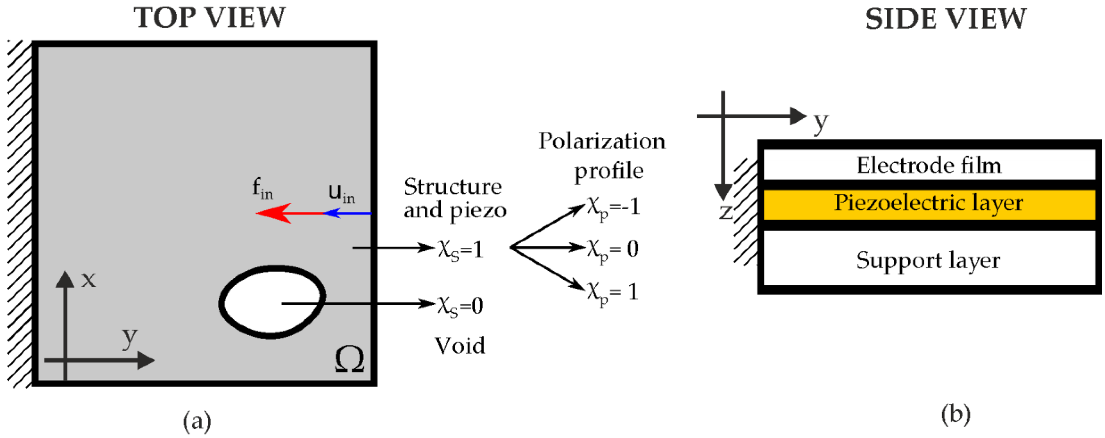
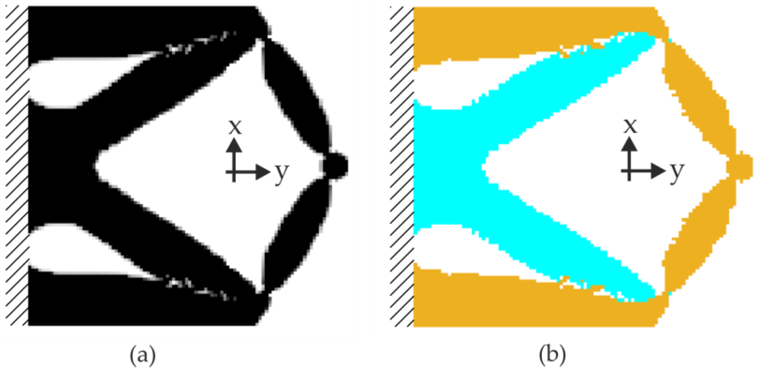
2.1. Optimal Design of the Actuators

The aim of the optimal design is the maximization of the displacement per unit voltage applied to the piezoelectric film, which is integrated in the MEMS actuator. It can be shown that this actuator problem is equivalent to the sensor problem, where the output charge generated by the same piezoelectric film is maximized when a mechanical force is applied [20]. The topology optimization method [21] allows the design of the polarization profile of the piezoelectric layer, hence improving the electrical signal generated by the piezoelectric effect.
The improvement of the generated output charge is set as an optimization problem that may be solved in a square domain called Ω. The plate is clamped at its left edge and the mechanical force is applied to the midpoint of the right edge, as shown in Figure 1a.
The side view of the multi-layered structure is shown in Figure 1b, the structure consisting of silicon as a conductive support layer and bottom electrode, aluminium nitride as the piezoelectric thin film and aluminium for the top electrode. The three layers are perfectly bonded and the stiffness of the piezoelectric material and the electrode film are neglected since their thicknesses are small compared to the silicon support layer.

2.1.1. Optimization Problem

The optimization problem proposed in the previous section involves two variables (characteristic functions): the structural variable, χ s , that models the topology of the structure, and the polarization profile of the electrodes,   χ p . The first one can take the two values χ s { 0 , 1 } , meaning void or solid, respectively. The polarization profile is a tri-level function, namely χ p { 1 , 0 , 1 } , meaning negative, null, or positive polarity of the electrode. Since the topology optimization problem lacks classical solutions, the design variables χ s and χ p need to be relaxed into the density variables ρ s [ 0 , 1 ] and ρ p [ 1 , 1 ] . As usual in topology optimization problems, after the relaxation of the variables, the domain is discretized in n e finite elements, with two variables per element.
Concerning the finite element model, bilinear elements with 8 degrees of freedom have been considered, assuming plane stress hypothesis. The interested reader is referred to [28]. The stiffness of the host structure is large enough to consider a linear elasticity modeling of the displacements of the sensor. The problem written as a topology optimization problem is as follows:
max ρ s , ρ p R ρ p B T U s . t . : K ( ρ s ) U =   F u i n ( ρ s ) u i n m a x   v T ρ s V m a x ρ s   ϵ [ 0 , 1 ] ρ p   ϵ [ 1 ,   1 ] ,
where R is an interpolation function that models the electric charge generated in the void elements, BT is the transposition of the usual strain matrix, U is the displacement vector, K is the stiffness matrix, F is the force vector (a vector of zeros with the value f i n placed at the input port), u i n is the displacement in the y-axis of the midpoint of the right edge, u i n m a x is the maximum displacement allowed in the point of application of the mechanical force, v is the finite element volume, and V m a x   is the maximum volume fraction allowed. The only way to control the stress in the structure is by limiting the maximum displacement at the input port. In addition, a constraint over the maximum amount of material is included to ease manufacturability [21,29].
Local minima issue is a classic difficulty in topology optimization problems. In order to deal with this unavoidable problem, continuation techniques are implemented, with the aim of obtaining the best possible design. The continuation method is used over the power p (penalization of the SIMP method), starting with p = 1 and increasing (linearly with the iterations) up to p = 3 and over the penalization function R, changing the slope in the 100th iteration to make it steeper. Concerning the initialization of the problem, the structural variable takes the same value in all the finite elements, preserving the maximum volume. The polarization profile starts with null polarity. This initialization, together with the continuation methods, has shown the best performance in the optimization problem.
A few words must be said about the optimization problem. The objective of the sensor problem is the maximization of the output charge for a given force, while the displacement at the input port is limited; but the problem can be written in the dual actuator form, where the objective function is the displacement at the input for a given voltage, and the constraint over the maximum displacement is replaced by a load spring that is added to the equilibrium equation. In the dual form of the problem, the piezoelectric force must be discretized and computed for an asymmetric actuator. The expressions for the in-plane and out-of-plane components can be found in [30]. The computations for obtaining these piezoelectric coefficients from the multi-layered structure are shown in [31]. Both references relate the piezoelectric force with the size of the finite element as well as with the stiffness of the different layers and the piezoelectric constants. The optimal design obtained in both problems is exactly the same, as was mathematically proven in [20].

2.1.2. Numerical Examples

In this section, two actuators for different values of maximum displacement allowed and input force are designed. The size of the square domain Ω is L = 1000   μ m . The thicknesses are t b = 100   μ m for the silicon support layer, t p = 620   nm for the piezoelectric film, and t e = 500   nm for the top electrode. The stiffness of the silicon layer is E = 130   GPa (the stiffness of the rest of the layers is neglected), and the Poisson's ratio is fixed to ν = 0.28 . In both examples, the volume fraction is set to V m a x = 0.5 . The domain Ω is discretized with a mesh of 100 × 100 elements.
For the first actuator, denominated as low-stiffness actuator, the force applied is fin = 1 N, and the maximum displacement allowed at the input port is u i n m a x = 20   μ m . The optimal design of the sensor is shown in Figure 2. The structure variable ρs is shown in Figure 2a, where black and white means solid (substrate and piezo) and void, respectively. The electrode profile is shown in Figure 2b, where cyan and orange represent regions with different polarity. The whole solid structure is covered by electrodes, otherwise the charge collected would be lower—only those parts of the structure that are covered by the electrodes are electrically affected. Once the topology and the polarization profile have been optimized, a continuous voltage of V i n = 50   V is applied to the structure, obtaining a calculated displacement of u i n = 27.28   nm in the y-axis.
For the second actuator, denominated as high-stiffness actuator, the mechanical force and the maximum displacement allowed are fixed to f i n = 10   N and u i n m a x = 50   μ m , while the rest of the parameters remain the same. The optimal design is shown in Figure 3. The structure variable and the polarization profile are shown in Figure 3a,b, respectively. In this case, after applying an input voltage of 50 V, the displacement calculated at the input port is u i n = 13.23   nm in the y-axis.

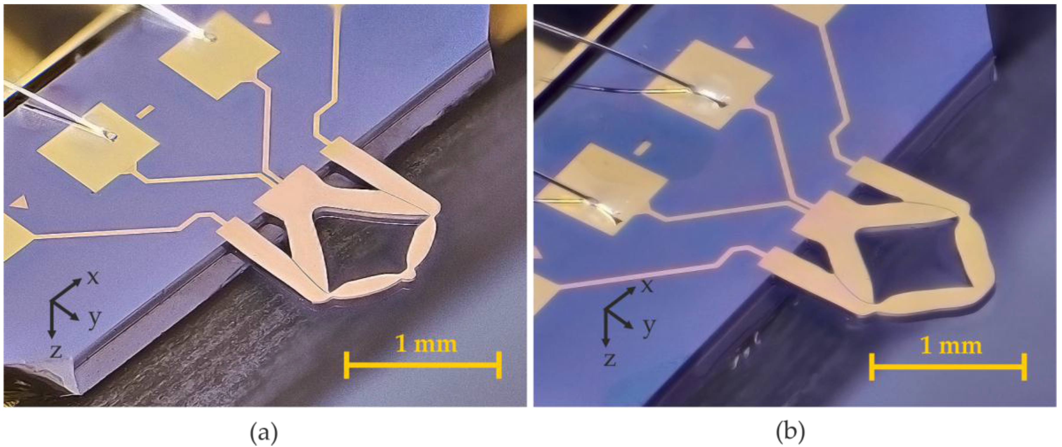
2.2. Final Design of the Actuators

In order to meet the restrictions of the fabrication process, minor modifications were introduced with respect to the mathematically optimal designs, as lateral dimensions of the structure narrower than 2 µm are not allowed. Regarding the electrodes, a minimum spacing between adjacent metal areas of different sign, which is determined by lithographical resolution and limitations from the etching process, were taken into account. This affects the displacement value negatively for both actuators. In order to obtain a displacement value closer to the final performance of the device, both actuators were also analyzed with a Finite Element Method (FEM) software [32]. As described in the previous section, an input of 50 V at 200 Hz was also applied for both resonators.
As can be seen in Table 1, the displacement values in the y-axis were lower for the final design than for the optimal design. In order to check that the excited mode was the targeted extensional mode, the displacements in the x-axis and z-axis, were also computed in the simulation.
As can be observed in Table 2, the displacements in the y-axis are in the same order of magnitude as the displacement in the z-axis. However, the displacements in the x-axis were almost zero.

2.3. Fabrication Process of the Actuators

The actuators were fabricated in-house from a SOI wafer with a 100-μm thick device layer covered with a 620-nm thick AlN piezoelectric film. This piezoelectric layer is sandwiched between 200-nm thick chromium/gold electrodes [33,34]. The thickness of the silicon support was chosen such that the extensional mode is observed at frequencies below 1 MHz. The top metallization has two electrodes that allow a selective excitation according to the design presented above. The actuators are excited by an anti-parallel connection of the electrodes (▲-) to obtain the desired extensional mode. The actuators have a length of L = 1000   μ m , a width of W = 1000   μ m , and a thickness of t b   100   μ m . Optical micrographs of the fabricated actuators are shown in Figure 4.

3. Results and Discussion

In the previous section, the simulated displacement values for the optimal and the real design were analyzed. For the experiments, three samples of each of the designs were used. Each sample was measured at least three times, and the following results were obtained from the average of all measurements taken for the samples of the same design. The measurements were carried out in quasi-static (200 Hz) conditions as well as at resonance. In addition, the elastic constant for both actuators was calculated.

3.1. Optical Measurements

Firstly, the actuators were characterized through optical measurements with a laser Doppler vibrometer, recording the out-of-plane displacement (perpendicular to the plane of the actuator), while applying a chirp signal of 3 V in the range of 1 to 1000 kHz. As can be seen in Figure 5 and Figure 6, the bending (out-of-plane) and the extensional (in-plane) modes present the greatest displacement values compared with other peaks of the spectrum.
It is highly remarkable from Figure 5 and Figure 6 that the low-stiffness actuator exhibited Q-factors as high as 1539 for the extensional mode, while the high-stiffness actuator exhibited a value of 143. The standard deviation of the quality factor of the extensional mode for the three low-stiffness actuators was 12, whereas for the high-stiffness device it was 5. This significantly lower performance of the latter, in terms of Q-factor, could be related to the dominant source of energy losses in air: fluid damping and anchor losses. Although both structures have the same anchor shape and size, anchor losses may depend on frequency [35]. In the case of fluid damping, in-plane and especially extensional modes, have demonstrated their good performance in terms of fluid damping in contrast to bending modes [36,37,38]. As can be seen from Figure 5 and Figure 6, both actuators’ extensional modes showed a significant out-of-plane deformation, which would devaluate their Q-factor. Moreover, the ratio of out-of-plane to in-plane deformation is higher in the high-stiffness actuator as well as the area with the greater deformation (i.e., the tip), so this actuator may suffer from greater damping, hence, even lower Q-factors are expected.

3.2. Electrical Measurements

In order to calculate the quality factor and the resonant frequency of the different devices and vibration modes, the measured electrical impedance spectrum was fitted to a modified Butterworth–Van Dyke equivalent circuit [39]. The equivalent RLC (Resistance-Inductance-Capacitance) values were obtained by fitting the conductance of the circuit model to the experimental conductance spectrum around resonance, obtaining the values shown in Table 3.

3.3. Analysis of the Displacement

In the next section, the results obtained in the simulations and the optically measured data will be compared. Moreover, in this section we used an optical tool from Optonor, Norway (MEMSMap 510), which consists of a speckle pattern interferometer capable of building a map of both the out-of-plane and the in-plane motion of the device surface [8]. In addition, the information on the mechanical displacement amplitude obtained with this instrument allows to determine the efficiency of the actuation and sensing mechanisms.

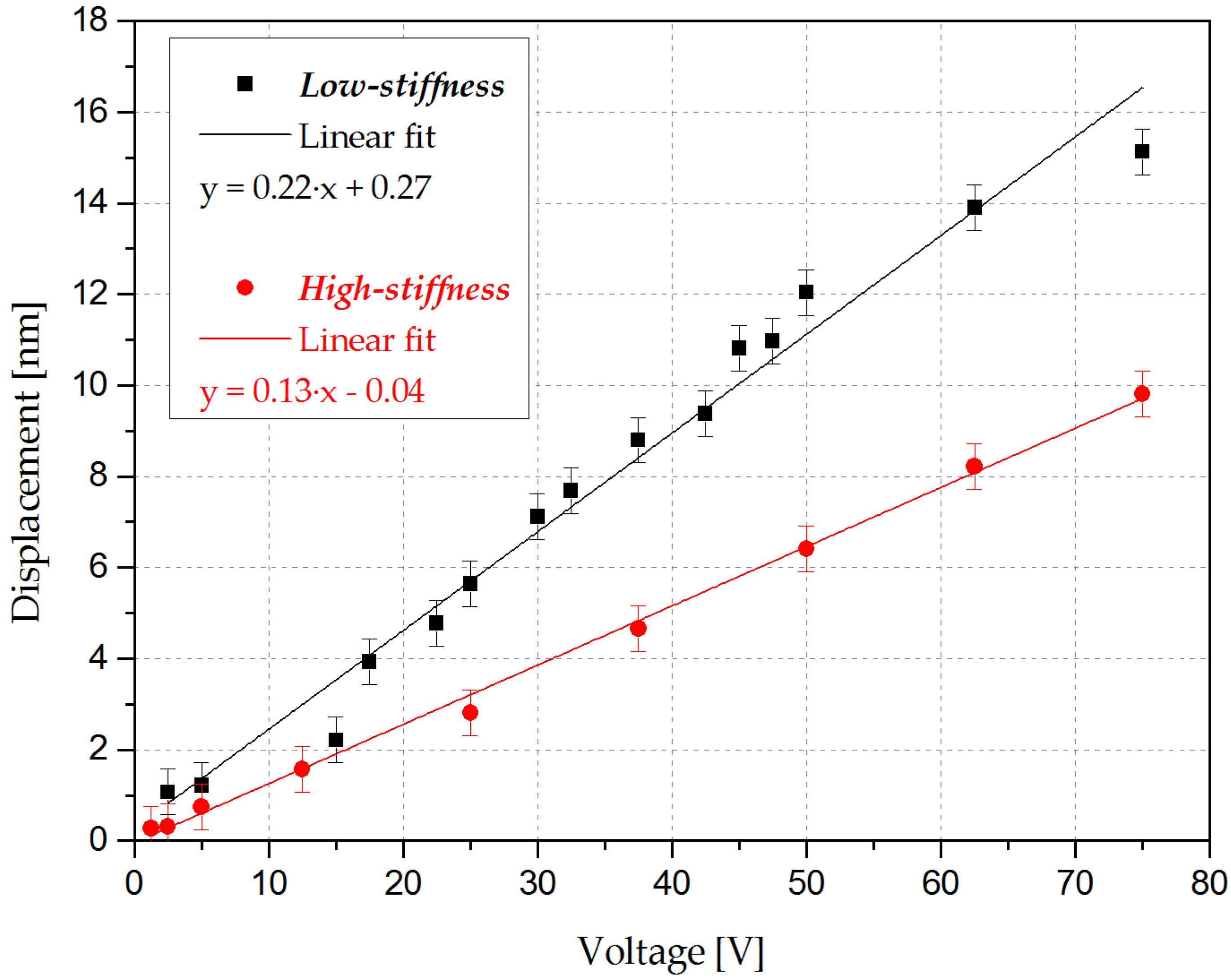
3.3.1. Analysis of the Displacement in Quasi-Static or DC Condition

In order to obtain the in-plane displacement for a given actuation voltage, a quasi-static analysis was carried out. Actuation voltages ranging from 2 to 75 V at a low frequency of 200 Hz, considerably far from the lowest resonant mode (see Figure 5 and Figure 6), were used.
As can be observed in Figure 7, the recorded displacement values followed a linear tendency; the sensitivity, which is equivalent to the displacement to voltage ratio, was obtained, yielding a value of 0.22 nm/V and 0.13 nm/V for the low-stiffness and the high-stiffness actuator, respectively.
The comparison with the simulated values (Table 4) revealed that the measured displacements were lower than those of the original optimal designs. This could be related to the slight modifications performed in the layout to meet the fabrication process requirements and to deviations in the fabrication process itself. These modifications may lead to a loss of optimality, which was more noticeable in the low-stiffness actuator since it required a higher thickening of the joints, while the fabrication tolerances affected both actuators more evenly.

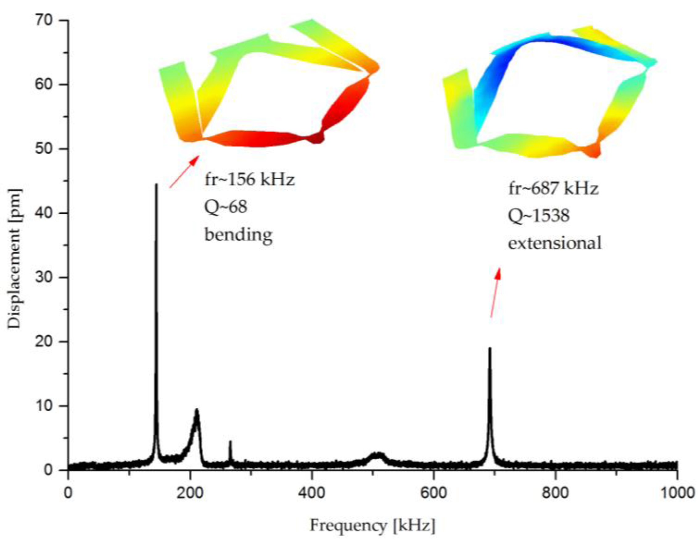
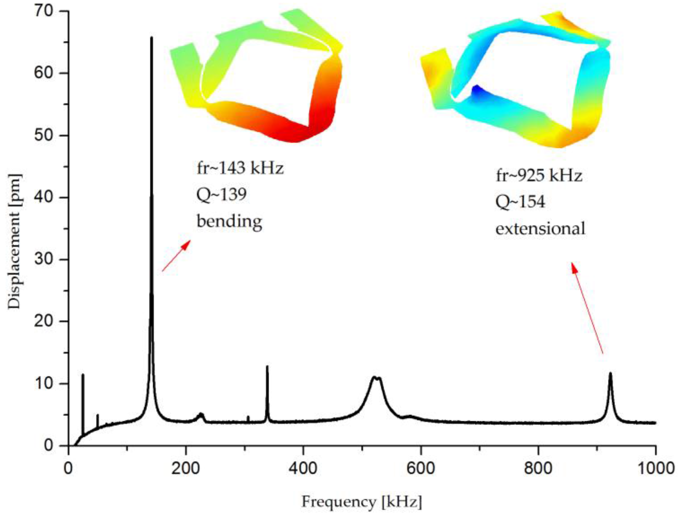
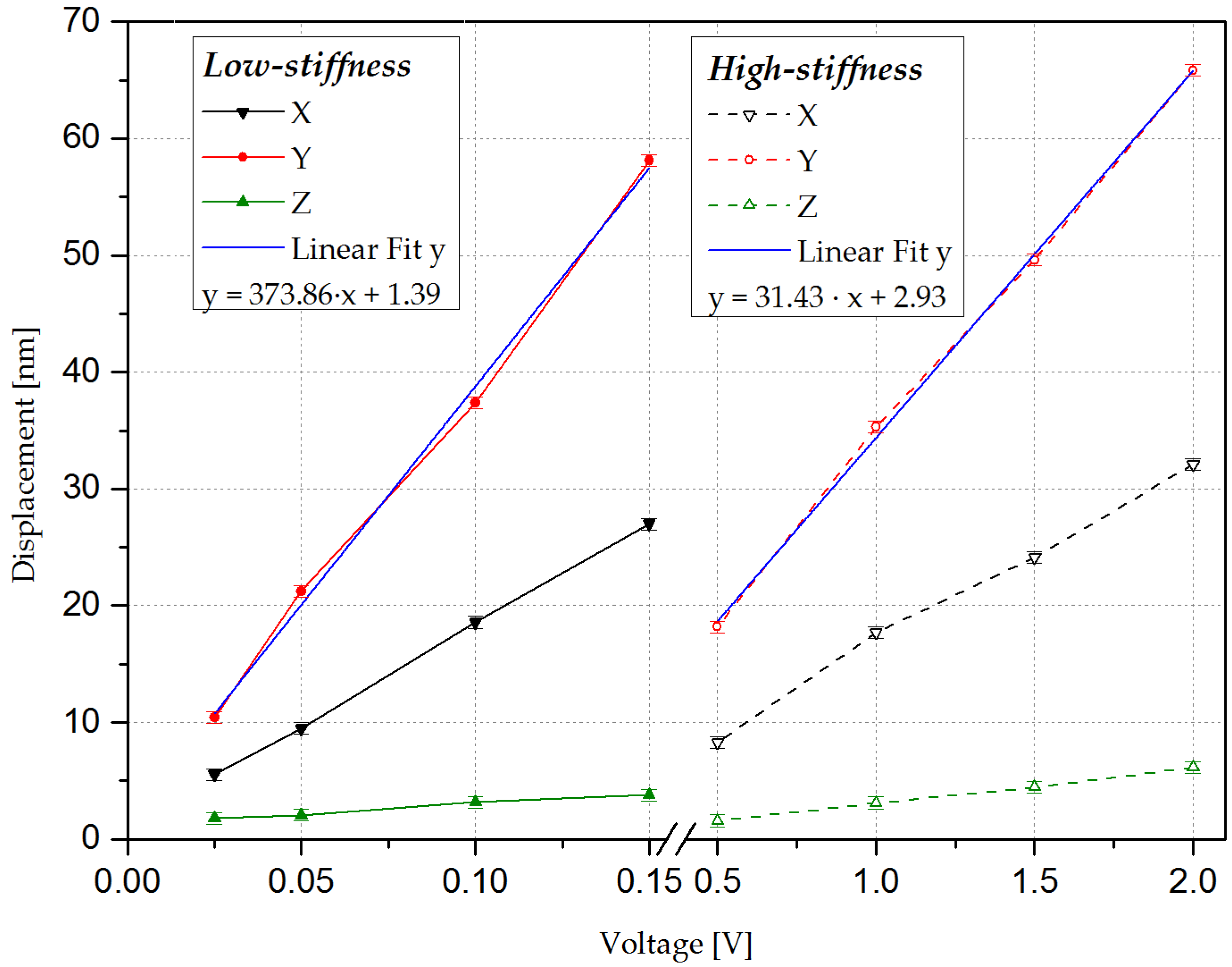
3.3.2. Analysis of the Displacement at the Resonant Frequency or AC

Once the actuators have been characterized in quasi-static excitation, the next step is to perform a study of the displacement at the resonant frequency. In this case, a sinusoidal voltage at each actuator’s resonant frequency and at an amplitude ranging from 0.025 to 0.15 V and 0.5 to 2 V for the low-stiffness and high-stiffness actuator, respectively, was carried out. In Figure 8, the displacement values in each direction at resonance are shown.

3.4. Analysis of the Elastic Constant

Assuming a linear relationship between response and excitation, the mechanical response of the actuators can be modeled as the superposition of an infinite number of resonance modes, each one corresponding to a single degree of freedom (SDOF) damped second order system [40]. Since each mode is determined by its own characteristic constants, i.e., mass ( m n ), stiffness ( k n ), and damping factor ( c n ), the frequency–domain analysis of a single mode is possible, provided that its resonant frequency is far enough from the frequency of any other mode. Equation (2) describes the displacement (d) to force (F) response of a SDOF mass–spring–damper system.
d F ( s ) = 1 m n s 2 + c n s + k n   ,
Following the procedure reported previously [8,41], we could transform the mechanical response into the electrical response of the actuator, obtaining Equation (3). Moreover, we could obtain Equation (4), which determines the electromechanical coefficient ( η n ) from the electrical coefficients and the displacement at resonance. By means of the MEMSMap 510, the ratio of the maximum displacement to the applied voltage in resonance, d / v   ( j ω n ) , was measured as in the previous section.
d v ( s ) = η n m n s 2 + c n s + k n   ,
η n = 1 R s ω n | d v ( j ω n ) |   ,
Once the electromechanical coefficient is known, the stiffness constant can be calculated as in Equation (5). This Equation expresses the suitability of the device to work as a modal in-plane actuator. In this Equation, two parts can be considered separately: the modal factor, Q, and the piezoelastic factor, having a ratio of η n to k n .
k n = η n Q | d v ( j ω n ) |   ,
In order to calculate the coefficients η n and k n , we used the linear fit values of Figure 8 and the electrical parameters obtained from the impedance measurements in Table 3. As can be observed in Table 5, the low-stiffness actuator presents the lowest stiffness. Furthermore, η n seems to increase with k n , while the ratio of η n to k n , representing the efficiency of actuation, presents the opposite tendency. Therefore, we can conclude that the low-stiffness actuator is suitable for use as a modal actuator at the quasi-static and the resonant frequency.

4. Conclusions

In this study, two different actuator designs were evaluated, both theoretically and experimentally: a low-stiffness and a high-stiffness actuator. Each actuator presented two different vibrational modes: out-of-plane and in-plane mode, denominated as bending and extensional mode, respectively. However, only the extensional mode was studied in the present work, due to its potential application as a modal in-plane actuator.
In order to characterize the extensional mode, different simulations were performed: one with the optimal design and the other with the final design adapted to the fabrication process. We could observe that the displacement values were superior for the low-stiffness actuator. This was also verified through optical measurements in a quasi-static analysis, obtaining a displacement per volt of 0.22 and 0.13 nm/V for the low-stiffness and high-stiffness actuator, respectively. The same process was carried out at the resonant frequency for the extensional mode, obtaining a displacement per volt of 373.86 and 31.43 nm/V for the low-stiffness and high-stiffness actuator, respectively. Therefore, we can conclude that the low-stiffness actuator is more suitable for application as a modal in-plane actuator.

Acknowledgments

This work was supported by the Spanish Ministerio de Economía y Competitividad and FEDER project TEC2015-67470-P and the Austrian Research Promotion Agency within the "Austrian COMET-Program" in the frame of K2 XTribology (project no. 849109). Javier Toledo acknowledges financial support from the FPI-BES-2013-063743 grant. The work of J.C. Bellido and A. Donoso was funded by MINECO (Spain) through grant MTM2013-47053-P and the work of Junta de Comunidades de Castilla-La Mancha (Spain) through grant PEII-2014-010-P.

Author Contributions

J. Toledo performed the experiments, analyzed the results, and wrote the paper; V. Ruiz-Díez also contributed with the experiments, analysis, and results; A. Díaz performed the simulations of the final design; D. Ruiz performed the optimal design and simulations; Alberto Donoso and José Carlos Bellido contributed with the optimal design. E. Wistrela, M. Kucera, and U. Schmid fabricated the actuators; J. Hernando-García and J.L Sánchez-Rojas conceived the idea and analyzed the results.

Conflicts of Interest

The authors declare no conflict of interest. The founding sponsors had no role in the design of the study; in the collection, analyses, or interpretation of data; in the writing of the manuscript, and in the decision to publish the results.

References

  1. Howe, R.T.; Muller, R.S.; Gabriel, K.J.; Trimmer, W.S.N. Silicon micromechanics: Sensors and actuators on a chip. IEEE Spectr. 1991, 27, 29–35. [Google Scholar] [CrossRef]
  2. Fujita, H. Microactuators and micromachines. Proc. IEEE. 1998, 86, 1721–1732. [Google Scholar] [CrossRef]
  3. Panchawagh, H.V.; Faheem, F.F.; Herrmann, C.F.; Serrell, D.B.; Finch, D.S.; Mahajan, R.L. Packaging of In-Plane Thermal Microactuators for BioMEMS Applications. In Proceedings of the ASME 2005 International Mechanical Engineering Congress and Exposition, Orlando, FL, USA, 5–11 November 2005; pp. 49–52. [Google Scholar]
  4. Eltagoury, Y.M.; Soliman, M.; Al-Otaibi, M.; Sabry, Y.M.; Sadek, M.; Khalil, D. In-plane comb-drive actuator with high frequency-displacement product for micro-optical bench applications. In Proceedings of the 2014 International Conference on Optical MEMS and Nanophotonics, Glasgow, UK, 17–21 August 2014; pp. 155–156. [Google Scholar]
  5. Grade, J.D.; Jerman, H.; Kenny, T.W. Design of Large Deflection Electrostatic Actuators. J. Microelectromec. Syst. 2003, 12, 335–343. [Google Scholar] [CrossRef]
  6. Ko, J.S.; Lee, M.L. Development and application of laterally driven electromagnetic microactuator. Appl. Phys. Lett. 2002, 81, 547–549. [Google Scholar] [CrossRef]
  7. Qui, J.; Lang, J.H.; Slocum, A.H.; Strümpler, R. A high-current electrothermal bistable MEMS relay. In Proceedings of the IEEE Sixteenth Annual International Conference on Micro Electro Mechanical Systems, Kyoto, Japan, 23–23 January 2003; pp. 64–67. [Google Scholar]
  8. Manzaneque, T.; Ruiz-Díez, V.; Hernando-García, J.; Ababneh, A.; Al-Omari, A.N.; Kucera, M.; Bittner, A.; Schmid, U.; Seidel, H.; Sánchez-Rojas, J.L. Piezoelectric in-plane microplate resonators based on contour and flexure-actuated modes. Microsyst. Technol. 2014, 20, 691–699. [Google Scholar] [CrossRef]
  9. Lee, F.Y.; Tang, T.L.; Fang, W. Development of a novel dual-axis large-displacement microstage using Lorentz force actuators and curved-beam springs. Procedia Eng. 2011, 25, 689–692. [Google Scholar] [CrossRef]
  10. Lv, X.D.; Wei, W.W.; Mao, X.; Yang, J.L.; Yang, F.H. A linear low driving voltage mems actuator with large lateral stroke driven by Lorentz force. In Proceedings of the 2015 Transducers—2015 18th International Conference on Solid-State Sensors, Actuators and Microsystems (TRANSDUCERS), Anchorage, AK, USA, 21–25 June 2015; pp. 2117–2120. [Google Scholar]
  11. Leang, K.K.; Fleming, A.J. High-speed serial-kinematic SPM scanner: Design and drive considerations. Asian J. Control. 2009, 11, 144–153. [Google Scholar] [CrossRef]
  12. Aktakka, E.E.; Peterson, R.L.; Najafi, K. A 3-DOF piezoelectric micro vibratory stage based on bulk-PZT/silicon crab-leg suspensions. In Proceedings of the 2013 IEEE 26th International Conference on Micro Electro Mechanical Systems (MEMS), Taipei, Taiwan, 20–24 January 2013; pp. 576–579. [Google Scholar]
  13. Conway, N.J.; Kim, S.G.G. Large-strain, piezoelectric, in-plane micro-actuator. In Proceedings of the 17th IEEE International Conference on Micro Electro Mechanical Systems, Maastricht MEMS 2004 Technical Digest, Maastricht, The Netherlands, 25–29 January 2004. [Google Scholar]
  14. Oldham, K.R.; Pulskamp, J.S.; Polcawich, R.G.; Dubey, M. Thin-film PZT lateral actuators with extended stroke. J. Microelectromech. Syst. 2008, 17, 890–899. [Google Scholar] [CrossRef]
  15. Yoshida, S.; Wang, N.; Kumano, M.; Kawai, Y.; Tanaka, S.; Esashi, M. Fabrication and characterization of laterally-driven piezoelectric bimorph MEMS actuator with sol–gel-based high-aspect-ratio PZT structure. J. Micromech. Microeng. 2013, 23, 065014. [Google Scholar] [CrossRef]
  16. Luo, Z.; Tong, L.; Luo, J.; Wei, P.; Wang, M.Y. Design of piezoelectric actuators using a multiphase level set method of piecewise constants. J. Comput. Phys. 2009, 228, 2643–2659. [Google Scholar] [CrossRef]
  17. Chen, S.; Gonella, S.; Chen, W.; Liu, W.K. A level set approach for optimal design of smart energy harvesters. Comput. Methods Appl. Mech. Eng. 2010, 199, 2532–2543. [Google Scholar] [CrossRef]
  18. Grossard, M.; Rotinat-Libersa, C.; Chaillet, N.; Boukallel, M. Mechanical and control-oriented design of a monolithic piezoelectric microgripper using a new topological optimization method. IEEE/ASME Trans. Mechatron. 2009, 14, 32–45. [Google Scholar] [CrossRef]
  19. Khadraoui, S.; Rakotondrabe, M.; Lutz, P. Optimal design of piezoelectric cantilevered actuators with guaranteed performances by using interval techniques. IEEE/ASME Trans. Mechatron. 2014, 19, 1660–1668. [Google Scholar]
  20. Ruiz, D.; Donoso, A.; Bellido, J.C.; Kucera, M.; Schmid, U.; Sánchez-Rojas, J.L. Design of piezoelectric microtransducers based on the topology optimization method. Microsyst. Technol. 2016, 22, 1733–1740. [Google Scholar] [CrossRef]
  21. Bendsøe, M.P.; Sigmund, O. Topology Optimization; Springer: Berlin/Heidelberg, Germany, 2004. [Google Scholar]
  22. Kögl, M.; Silva, E.C.N. Topology optimization of smart structures: Design of piezoelectric plate and shell actuators. Smart Mater. Struct. 2005, 14, 387–399. [Google Scholar] [CrossRef]
  23. Carbonari, R.C.; Silva, E.C.N.; Nishiwaki, S. Optimum placement of piezoelectric material in piezoactuator design. Smart Mater. Struct. 2007, 16, 207–220. [Google Scholar] [CrossRef]
  24. Luo, Z.; Gao, W.; Song, C. Design of Multi-phase Piezoelectric Actuators. J. Intell. Mater. Syst. Struct. 2010, 21, 1851–1865. [Google Scholar] [CrossRef]
  25. Molter, A.; Fonseca, J.S.O.; Fernandez, L.D.S. Simultaneous topology optimization of structure and piezoelectric actuators distribution. Appl. Math. Model. 2016, 40, 5576–5588. [Google Scholar] [CrossRef]
  26. Kang, Z.; Wang, R.; Tong, L. Combined optimization of bi-material structural layout and voltage distribution for in-plane piezoelectric actuation. Comput. Methods Appl. Mech. Eng. 2011, 200, 1467–1478. [Google Scholar] [CrossRef]
  27. Kang, Z.; Wang, X.; Luo, Z. Topology Optimization for Static Shape Control of Piezoelectric Plates with Penalization on Intermediate Actuation Voltage. J. Mech. Des. 2012, 134, 051006. [Google Scholar] [CrossRef]
  28. Cook, R.D.; Malkus, D.; Plesha, M. Concepts and Applications of Finite Element Analysis, 3rd. ed.; Wiley: New York, NY, USA, 1989. [Google Scholar]
  29. Ruiz, D.; Bellido, J.C.; Donoso, A.; Sánchez-Rojas, J.L. Design of in-plane piezoelectric sensors for static response by simultaneously optimizing the host structure and the electrode profile. Struct. Multidiscip. Optim. 2013, 48, 1023–1026. [Google Scholar] [CrossRef]
  30. Gibbs, G.P.; Fuller, C.R. Excitation of thin beams using asymmetric piezoelectric actuators. J. Acoust. Soc. Am. 1992, 92, 3221–3227. [Google Scholar] [CrossRef]
  31. Moheimani, S.O.R.; Fleming, A.J. Piezoelectric Transducers for Vibration Control and Damping; Springer-Verlag: London, UK, 2006. [Google Scholar]
  32. Coventor Ware. Available online: http://www.coventor.com/mems-solutions/products/coventorware/ (accessed on 3 June 2017).
  33. Kucera, M.; Hofbauer, F.; Wistrela, E.; Manzaneque, T.; Ruiz-Díez, V.; Sánchez-Rojas, J.L.; Bittner, A.; Schmid, U. Lock-in amplifier powered analogue Q-control circuit for self-actuated self-sensing piezoelectric MEMS resonators. Microsyst. Technol. 2014, 20, 615–625. [Google Scholar] [CrossRef]
  34. Kucera, M.; Wistrela, E.; Pfusterschmied, G.; Ruiz-Díez, V.; Manzaneque, T.; Hernando-García, J.; Sánchez-Rojas, J.L.; Jachimowicz, A.; Schalko, J.; Bittner, A.; Schmid, U. Design-dependent performance of self-actuated and self-sensing piezoelectric-AlN cantilevers in liquid media oscillating in the fundamental in-plane bending mode. Sens. Actuators B Chem. 2014, 200, 235–244. [Google Scholar] [CrossRef]
  35. Segovia-Fernandez, J.; Cremonesi, M.; Cassella, C.; Frangi, A.; Piazza, G. Experimental study on the impact of anchor losses on the quality factor of contour mode AlN resonators. In Proceedings of the 2013 Transducers & Eurosensors XXVII: The 17th International Conference on Solid-State Sensors, Actuators and Microsystems (TRANSDUCERS & EUROSENSORS XXVII), Barcelona, Spain, 16–20 June 2013; pp. 2473–2476. [Google Scholar]
  36. Castille, C.; Dufour, I.; Lucat, C. Longitudinal vibration mode of piezoelectric thick-film cantilever-based sensors in liquid media. Appl. Phys. Lett. 2010, 96, 154102. [Google Scholar] [CrossRef]
  37. Manzaneque, T.; Ruiz, V.; Hernando-García, J.; Ababneh, A.; Seidel, H.; Sánchez-Rojas, J.L. Characterization and simulation of the first extensional mode of rectangular micro-plates in liquid media. Appl. Phys. Lett. 2012, 101, 151904. [Google Scholar] [CrossRef]
  38. Ruiz-Díez, V.; Hernando-García, J.; Manzaneque, T.; Kucera, M.; Schmid, U.; Sánchez-Rojas, J.L. Viscous and acoustic losses in length-extensional microplate resonators in liquid media. Appl. Phys. Lett. 2015, 106, 083510. [Google Scholar] [CrossRef]
  39. Arnau, A.; Sogorb, T.; Jimenez, Y. A continuous motional series resonant frequency monitoring circuit and a new method of determining Butterworth-Van Dyke parameters of a quartz crystal microbalance in fluid media. Rev. Sci. Instrum. 2000, 71, 2563–2571. [Google Scholar] [CrossRef]
  40. Gatti, P.L.; Ferrari, V. Applied Structural and Mechanical Vibrations. CRC Press: Boca Raton, FL, USA, 2003. [Google Scholar]
  41. Ho, G.K.; Abdolvand, R.; Sivapurapu, A.; Humad, S.A.H.S.; Ayazi, F.A.A.F. Piezoelectric-on-Silicon Lateral Bulk Acoustic Wave Micromechanical Resonators. J. Microelectromec. Syst. 2008, 17, 512–520. [Google Scholar] [CrossRef]
Figure 1. Design domain and boundary conditions: (a) top view; (b) side view. χ s and χ p are the material and polarization profile design variables, respectively. The force f i n and displacement u i n at the input port are also depicted.
Actuators 06 00019 g001
Figure 2. Low-stiffness actuator: (a) structure variable; (b) polarization profile for f i n = 1   N and u i n m a x = 20   μ m
Actuators 06 00019 g002
Figure 3. High-stiffness actuator: (a) structure variable; (b) polarization profile for f i n = 10   N and u i n m a x = 50 µm.
Actuators 06 00019 g003
Figure 4. Micrograph of the MEMS actuators: (a) low-stiffness actuator; (b) high-stiffness actuator.
Actuators 06 00019 g004
Figure 5. Average out-of-plane displacement (z-axis) from the optical characterization of the low-stiffness actuator. The measured modal shape and estimated quality factor are shown next to each peak.
Actuators 06 00019 g005
Figure 6. Average out-of-plane displacement (z-axis) from the optical characterization of the high-stiffness actuator. The measured modal shape and estimated quality factor are shown next to each peak.
Actuators 06 00019 g006
Figure 7. Average displacement in the y-axis at 200 Hz as a function of the applied voltage and its linear fit. The error bar represents the measurement resolution (1 nm).
Actuators 06 00019 g007
Figure 8. Average displacement at the resonant frequency as a function of the applied voltage and its linear fit.
Actuators 06 00019 g008
Table 1. Comparison of the simulated displacement values between the optimal and the final design with an input of 50V at 200 Hz.
ActuatorSimulationsDisplacement y-axis (nm)
Low stiffnessOptimal27.28
Final16.85
High stiffnessOptimal13.23
Final11.22
Table 2. Comparison of the simulated displacement values for the final design with an input of 50V at 200 Hz.
ActuatorDisplacement x-axis (nm)Displacement y-axis (nm)Displacement z-axis (nm)
Low stiffness5.09 × 10−316.859.12
High stiffness3.36 × 10−311.2218.57
Table 3. Fitted parameters from the impedance measurements in air for both actuators. The resonant frequency (fr) and quality factor (Q) were estimated from the equivalent circuit parameters: parallel capacitance (C0), series resistance, inductance, and capacitance (Rs, Ls, and Cs).
ActuatorVibration Modefr (kHz)QC0 (pF)Rs (kΩ)Ls (H)Cs (fF)
Low-stiffnessBending15668952340.01636.37
Extensional687153913551.018.22.95
High-stiffnessBending143139140232.036.034.30
Extensional925154145110.02.910.10
Table 4. Comparison of the simulated and measured displacement values in the y-axis with an input of 50 V at 200 Hz.
ActuatorSimulationsOptical Measurements
Optimal (nm)Final (nm)Fabricated Device (nm)
Low-stiffness27.2816.8512.04
High-stiffness13.2311.226.40
Table 5. Measured displacement at resonance for the extensional mode and coefficients derived.
ActuatorVibrational ModeDisplacement/V (nm/V) η n (N/V) k n (N/m) η n / k n (m/V)
Low stiffnessExtensional373.861.22 × 10−55.01 × 1042.43 × 10−10
High stiffnessExtensional31.434.97 × 10−52.45 × 1052.02 × 10−10

