A Novel Mechanically Overdamped Actuator with Adjustable Stiffness (MOD-AwAS) for Safe Interaction and Accurate Positioning

1
Department of Mechanical Engineering, Ehime University, 3 Bunkyo-cho, Matsuyama, Ehime 790-8577, Japan
2
Advanced Robotic Manipulators (ARM) Lab, Department of Mechanical Engineering, University of Texas at San Antonio (UTSA), One Circle, San Antonio, TX 78249, USA
*
Author to whom correspondence should be addressed.
Actuators 2017, 6(3), 22; https://doi.org/10.3390/act6030022
Submission received: 23 May 2017
/
Revised: 16 June 2017
/
Accepted: 19 June 2017
/
Published: 28 June 2017
(This article belongs to the Special Issue Variable Stiffness and Variable Impedance Actuators)
Abstract
:This paper presents the design and development of a novel mechanically overdamped actuator with adjustable stiffness (MOD-AwAS). The novelty of MOD-AwAS compared to other variable stiffness actuators relates to its mechanical design, which prevents oscillations at the output link. Almost all variable stiffness actuators have an overshooting problem that require a sophisticated control algorithm to be able to perform accurate positioning. MOD-AwAS can regulate the stiffness from zero to its maximum (theoretically infinite) in less than 0.2 s by changing the position of the pivot point of its lever mechanisms. MOD-AwAS employs only one rotational spring with no pre-deflection, which gives it full accessibility to its energy storage capacity. Experimental results are presented to show the ability of MOD-AwAS to control its position accurately with a wide range of stiffness adjustment.
1. Introduction
Variable stiffness actuators (VSAs) are a new generation of robotic actuators that are proposed to allow for stiffness adjustment in addition to the ability to tune their position [1,2,3,4,5,6]. This stiffness adjustability is essential in many applications, especially in physical human–robot-interactions (pHRI) where robots and humans work in close vicinity [7,8,9,10,11,12,13]. Safety can be guaranteed as having an elastic element, e.g., a spring, allows for inherent mechanical compliance to be built into traditionally rigid components.
Despite the numerous advantages of VSAs, using them often leads to difficulty in applications, necessitating high accuracy or precision [1,14]. By building in inherent mechanical compliance, the true position of the end effector will differ from the position of the motor any time the system is disturbed. This problem can be amplified considerably in joints that do not also incorporate some type of damping in their control systems [15]. As a result, oscillation and over shooting is always an unavoidable phenomenon in these type of actuators. This overshooting is also a critical concern when safety is a prime goal. Overshooting signifies releasing the potential energy stored in the spring, which in high-speed scenarios, e.g., step response, could lead to high and uncontrollable output power. This would result in a chaotic motion of the output link that can easily pose a critical danger to around human beings [16,17,18].
In order to address these issues, developers of VSAs have to implement sophisticated control algorithms that take into account the output link’s velocity and model-based stiffness at each instance over time. Then, through some linearization techniques, the best performance of the system, i.e., the minimum overshooting or settling time, can be achieved [5,11,19,20,21,22,23,24,25,26]. These types of control approaches always come along with their intrinsic constraints of maximum velocity and change in the stiffness that limits their advantages in practical applications [22,27].
Here we propose a mechanically overdamped actuator with adjustable stiffness (MOD-AwAS) as shown in Figure 1. This actuator tackles the oscillation problem with a different approach. Instead of relying on the control part to accurately position the moving complaint link, the system is designed to mechanically overdamp the motion. This is done by implementing stepwise impedance of the output link by allowing the impact of two rigid bodies. In this case, part of the kinetic energy of the output link will be dragged out from the system, and thus the output link will be immediately settled to its target position without a need for any control. The intended application of this actuator is where safety and accurate positioning are the critical determinants. Of course, killing the kinematic energy cannot be geared towards energy optimization, especially for the applications that contain periodic motions.
In addition to being mechanically overdamped, the output link of MOD-AwAS has full access to the energy storage capacity of its stiffness adjustment mechanism. The maximum energy that can be stored inside stiffness adjustment mechanism in VSAs can be determined by (1): the number of the springs; (2): the maximum deflection, and (3): the stiffness of each of them [10]. In antagonistic VSAs [1,10], this maximum energy storage can never be fully accessible from the output link side as part of this capacity is always taken for stiffness regulation and torque-generation purposes. In serial VSAs [28,29,30], part of this energy should be assigned for torque-generation purposes as the tension of the spring is the driving force of the output link. Also, in actuators with adjustable stiffness (AwAS) [31] and AwAS-II [28], part of this capacity is wasted due to the required pre-deflection of the springs. In these actuators, two springs are placed on both sides of a lever. Once the lever becomes fully deflected in one direction, one spring become fully compressed while the other one reaches its no-load length. That justifies the necessity of pre-deflection for the springs in these designs. MOD-AwAS, however, employs only one rotational spring. The spring is placed with no pre-deflection, therefore, no energy is wasted for this reason. It also employs a lever mechanism to regulate the stiffness, therefore, the full amount of energy that can be stored inside the spring is accessible at the output link. This implies that with a strong spring, the output link of MOD-AwAS can reach a high velocity which is helpful in highly dynamic tasks, but it will continue not to have any, or minimal, oscillation around its equilibrium position. This is a unique feature of MOD-AwAS.
The rest of this paper is organized as follows: in Section 2 the modeling of the stiffness adjustment mechanism will be presented. Section 3 explains the overdamping properties and its implementation within the mechanical design of MOD-AwAS through some preliminary experiments. Finally, Section 4 talks about conclusion and future works.
2. Stiffness Modeling and Design
As mentioned previously, the stiffness adjustment mechanism of MOD-AwAS is the same as that of AwAS-II [28]. A lever is connected to a rotary spring from one end and perceives force from its other end, while being able to rotate around a pivot point. The lever has a U-shaped structure where the pivot can travel inside from one end to the other. The rotary spring also forms a U-shape and is placed concentrically with the lever. This is geared toward the compactness of the system. The schematic of stiffness adjustment mechanism of MOD-AwAS is shown in Figure 2.
2.1. Stiffness Formulation
Once force F is applied to the lever at the tip of its leg, the lever becomes deflected. The lever is connected to the rotary spring at the tip of the leg (Figure 2.). However, this connection is unidirectional. It means that depending of the direction of force F and consequently the rotation of the lever, only one of the spring’s legs become deflected at a time, while the other leg losses the connection with the lever (as shown in Figure 2).
Let us assume that the pivot is located at the distance of L1 from the center of rotation of the lever, and L2 from the force point. The distance between center of rotation of the lever and that of the output link is L, as depicted in Figure 2. The rotary spring has a stiffness of K. As the link become deflected by θ, the lever rotates around the pivot by α:
and thus, springs become deflected by x:
and the spring’s rotary deflection β will be:
Therefore, the torque acting on the spring Ts can be found as:
and thus, for small deflections, the force acting on the spring at its connection point with the lever, would be:
This force will balance the force acting on the other side of the lever F, therefore:
This force will be acting on the output link at the distance of L from its center of rotation. Consequently, the torque on the output link will be:
Therefore, using Equations (1)–(7), the rotary stiffness perceived at the link side Klink can be simplified as
for small deflections. As shown in Figure 3, a mechanical block around the lever limits the deflation to small amounts.
2.2. Damping Specification
The rigid collision between the spring’s “undeflected” leg and the lever is the underlying principle which helps the system to be mechanically overdamped. As the force is removed and the lever bounces back to its equilibrium point, there will be a rigid-rigid collision between the spring leg and that of the lever. This impact between two rigid elements will suddenly “kill” the kinetic energy and, consequently, the lever will stop right at its equilibrium position.
From the energy point of view, the kinetic Ekinetic and potential Epotential energy of the output link are:
where Ilink and dθ/dt are the inertia and velocity of the output link, respectively. Initially when the link is deflected due to an external force, kinetic energy is zero and zero potential energy is:
where θmax is the maximum deflection of the link (~0.3 rad). Once the force is removed, the link will accelerate, and the speed increases accordingly. The increase in speed, increases the kinetic energy, and simultaneously the potential energy will be reduced as the deflection decreases. The total energy will remain constant. Just before the link reaches its equilibrium position (before collision), its speed reaches the maximum level and deflection tends to zero, therefore:
The total energy of the link will remain constant until the collision. Therefore, we using Equations (10) and (11), we can determine the link maximum velocity as:
Right after the collision, the output link velocity will be dropped to (dθ/dt)ac. Therefore, the link kinetic and potential energy after collision will be:
The total energy of the system will reduce after the collision. We define a parameter as damping scale DS as:
DS is a function of link stiffness. In our system, the DS parameter is usually very small (see Section 4), particularly for high stiffness values. The higher the stiffness, the more energy will be taken out from the system at the moment of the collision. The link overshoot θos can be found as:
A small DS implies a large reduction in the speed after the collision, and that would lead to a small link overshoot, which is negligible for high stiffness values. This means that our system is mechanically overdamped particularly when the output link is highly compliant. This is geared toward safety since a low compliance link will have no oscillation as it will be overdamped. A high compliance link with a small amount of overshooting will also be safe to interact with as it will not pose any danger during a collision with a human body. The accuracy of positioning, however, will be affected by the link overshooting.
2.3. Accessibility of the Link to Energy Storage Capacity
Safety of interaction is a critical factor when a robotic arm touches a human body. In such cases, the arm should be easily deflectable to guarantee that the impact is controlled and not harmful. The more range of allowable deflection of the output link gives more time to the robot, sensors and controller to react, thus a more safe interaction can be achieved. Deflection of the output link is due to the deflection of the spring. In other word, the potential energy of the output link is linked to the potential energy of the spring. In most of VSAs, the link has very limited accessibility to the potential energy of the springs, which can greatly limit the deflection range of the output link or output power.
In MOD-AwAS, the maximum potential energy that can be stored into spring is:
where βmax is the maximum angular deflection of the spring. Using Equation (3), the maximum linear deflection of the spring leg at its contact point with the lever for small deflections can be found as:
and using Equation (2), the maximum link deflection will be:
By plugging Equations (8), (17) and (18) into Equation (10), the maximum potential energy of the output link can be found as:
It is clear that this energy is exactly the same as potential energy of the spring in Equation (16). Therefore, theoretically, the output link in MOD-AwAS has full access to the energy storage capacity of the spring.
3. Physical Implementation and Preliminarily Experiments
3.1. Physical Implementation
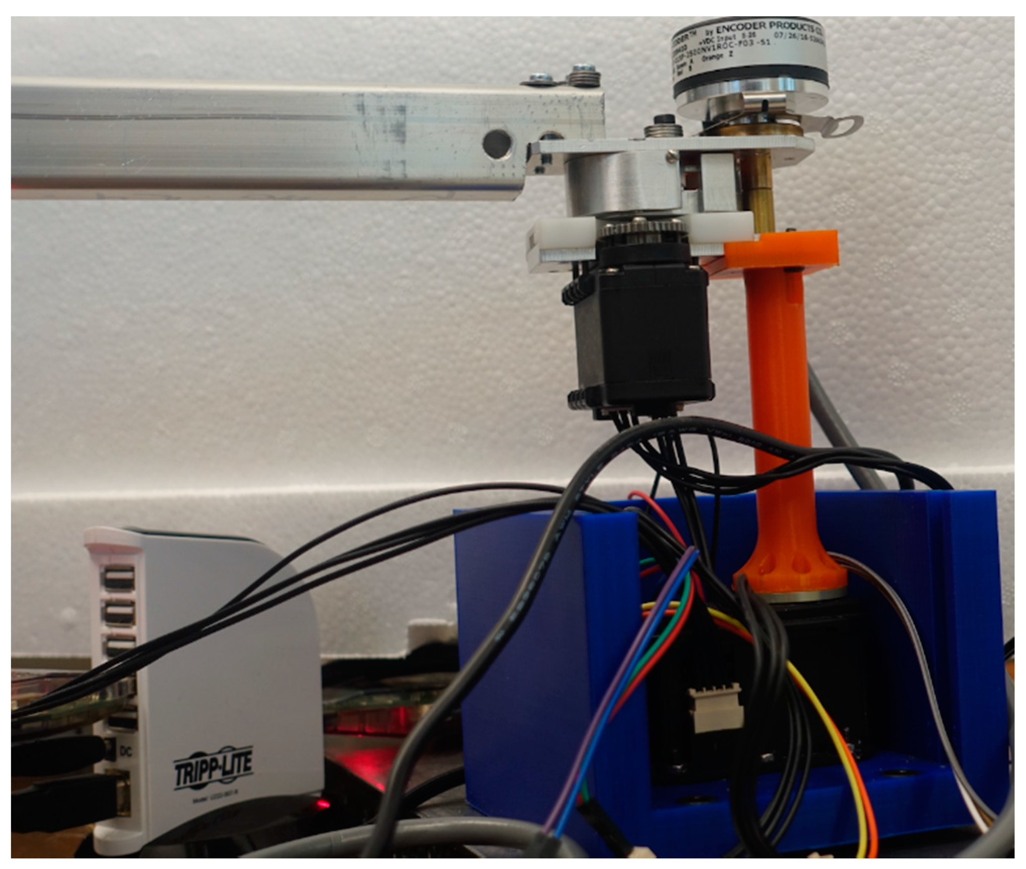
The MOD-AwAS prototype has two motors: one motor is dedicated to link positioning and the other smaller motor is assigned to stiffness regulation. In order to move the pivot point inside the lever using the second motor, we employed a rack and pinion mechanism. The rack is mounted on the lever and the pinion is assembled on the second motor shaft. The output link is attached to a light aluminum bar with the length of 50 cm in order to achieve a more distinguishable overshooting. We use a rotational spring with the stiffness of 10 Nm/rad as the elastic element. The maximum deflection of this rotary spring is around 60°. The system is mounted on a table for the purpose of experiments. The physical specifications of MOD-AwAS are presented in Table 1. The angular position of the two motors is measured through their built-in position sensors, while the position of the output link can be read using a rotary encoder attached to it. The difference between the first motor position and that of the output link, the angular deflection of the output link, can be calculated.
3.2. Preliminarily Experiments
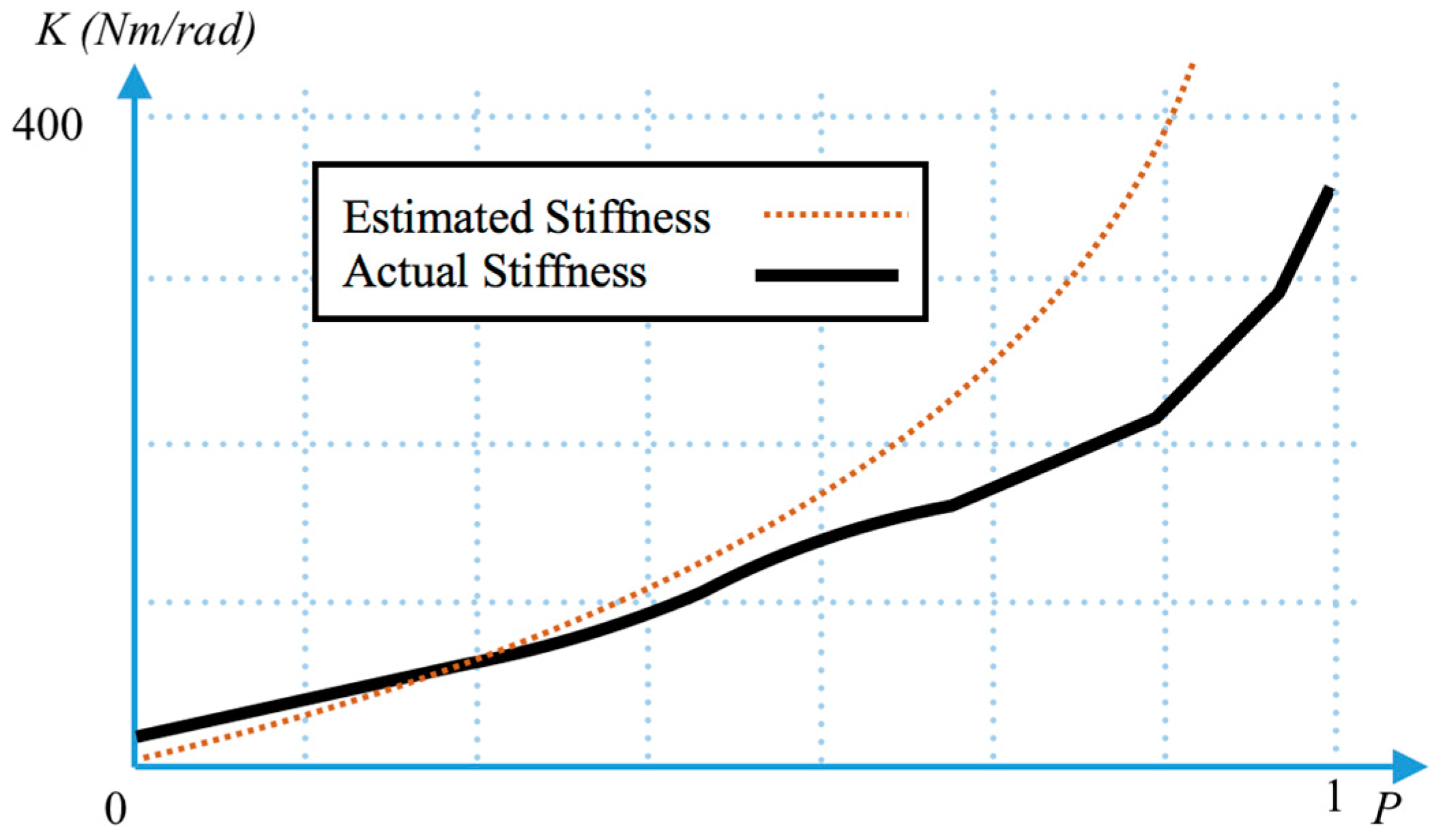
First, we test the stiffness adjustability and range of MOD-AwAS. For this purpose, we first set the stiffness to different values by controlling the position of the pivot inside the lever using the second motor. For each stiffness value, we attached a known set of different weights to the output link and measure the defection of output link due to the gravitational force. Stiffness is then calculated by dividing the force to angular deflection of the link. Figure 4 shows the stiffness as a function of pivot position p = L2/Llever inside the lever compared to the stimulated stiffness based on Equation (8). As shown by the graph, the stiffness of MOD-AwAS can vary from almost 32 Nm/rad to 350 Nm/rad. The reason we cannot achieve infinite stiffness is due to the backlash between the pivot and the lever. Furthermore, zero stiffness cannot be achieved because the actual connection between the lever and spring is not a point contact.
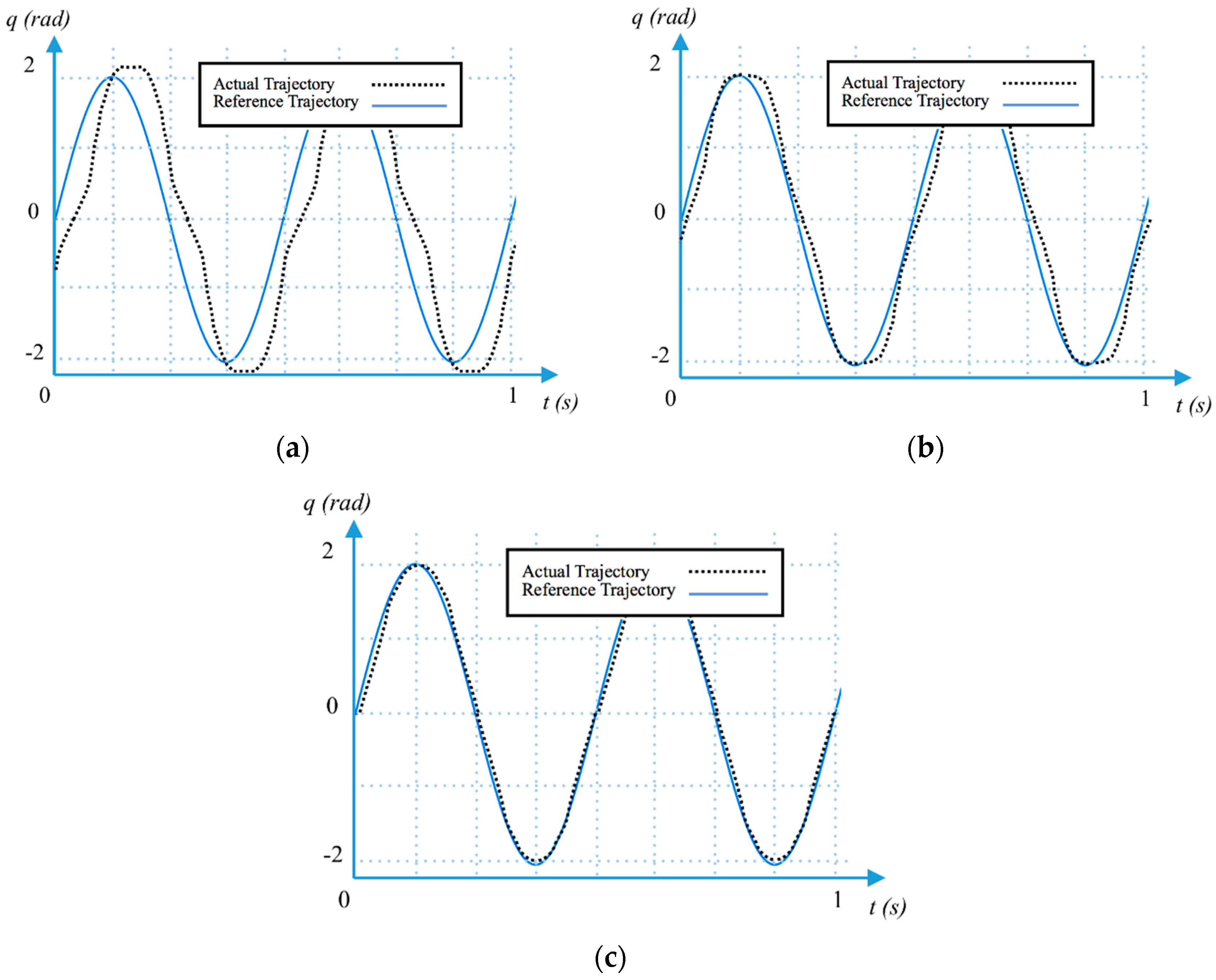
We then set the stiffness to three different values, very low (35 Nm/rad), low (50 Nm/rad), and high (300 Nm/rad), and commanded the output link to follow a sinusoidal trajectory with the amplitude of 0.2 rad and a frequency of 2 Hz. Figure 5 shows how the output link followed the reference trajectories for these stiffness values.
As shown in Figure 5, when the link stiffness is very low, there is a considerable phase delay between the reference trajectory and the link actual trajectory. There is also a little bit of overshooting when the link stiffness is very low. When the link stiffness is low, there is a very small phase delay between the reference trajectory and the link actual trajectory, while no overshooting is experienced. At high stiffness, no overshooting and phase delay between the actual link and reference trajectories is noticed.
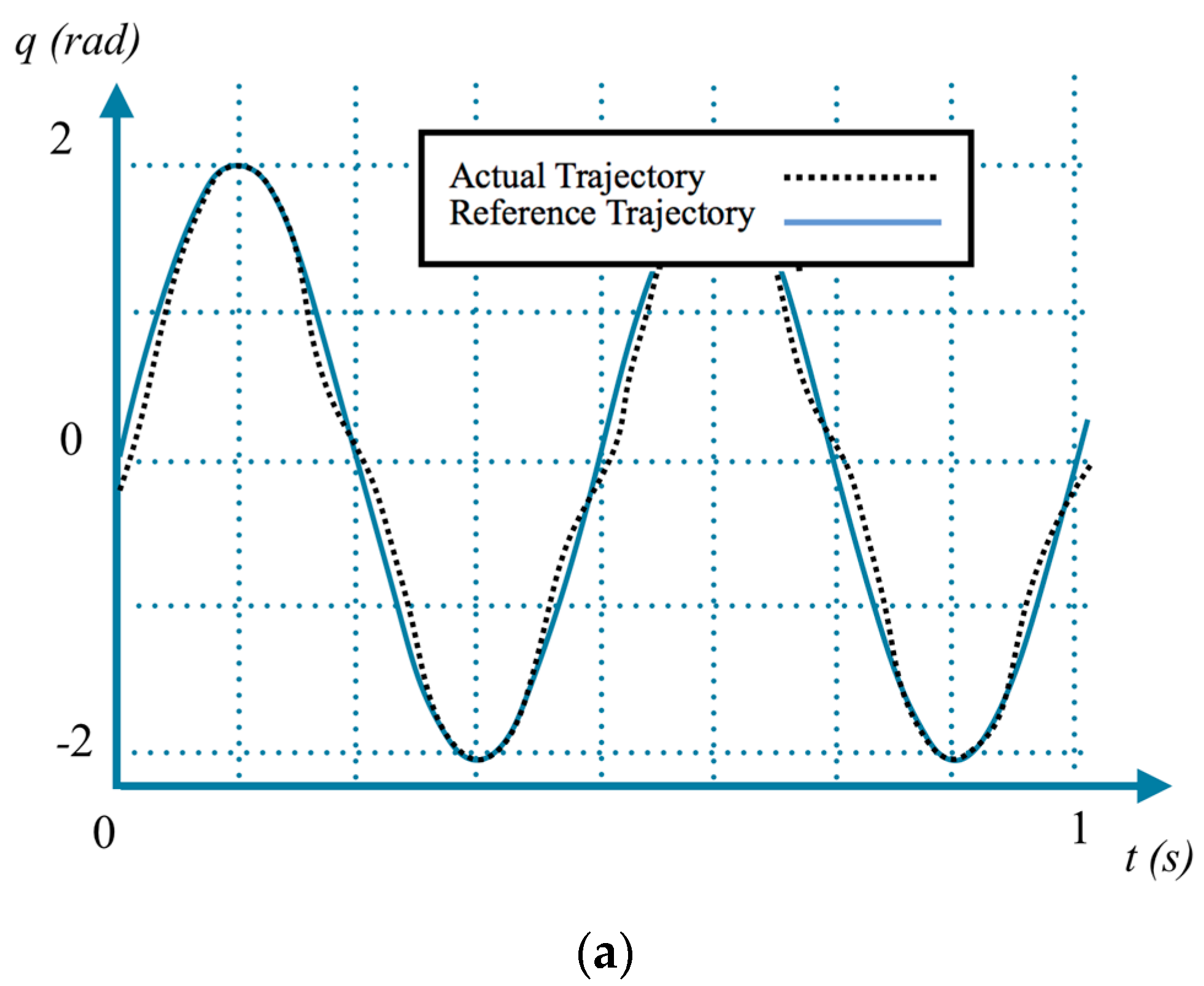
We also commanded the output link to follow the same reference trajectory, while the stiffness in changing on-line follows a sinusoidal trajectory from 35 Nm/rad to 300 Nm/rad with 4 Hz frequency. The result is depicted in Figure 6. As shown in the graph, the stiffness motor is able to follow its reference trajectory accurately. While the stiffness is low, the output link has some deviation from its reference trajectory. However, as the stiffness increased, the output link deviation tended to vanish.
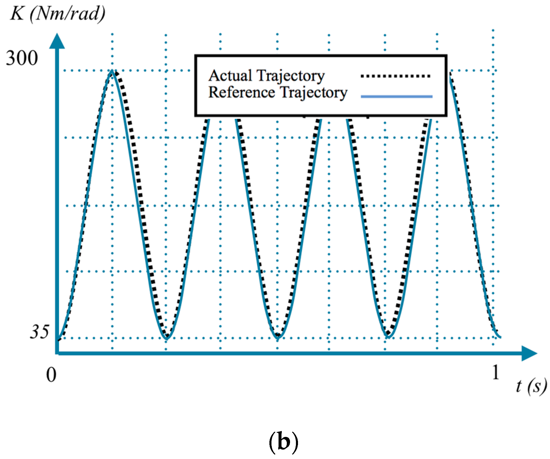
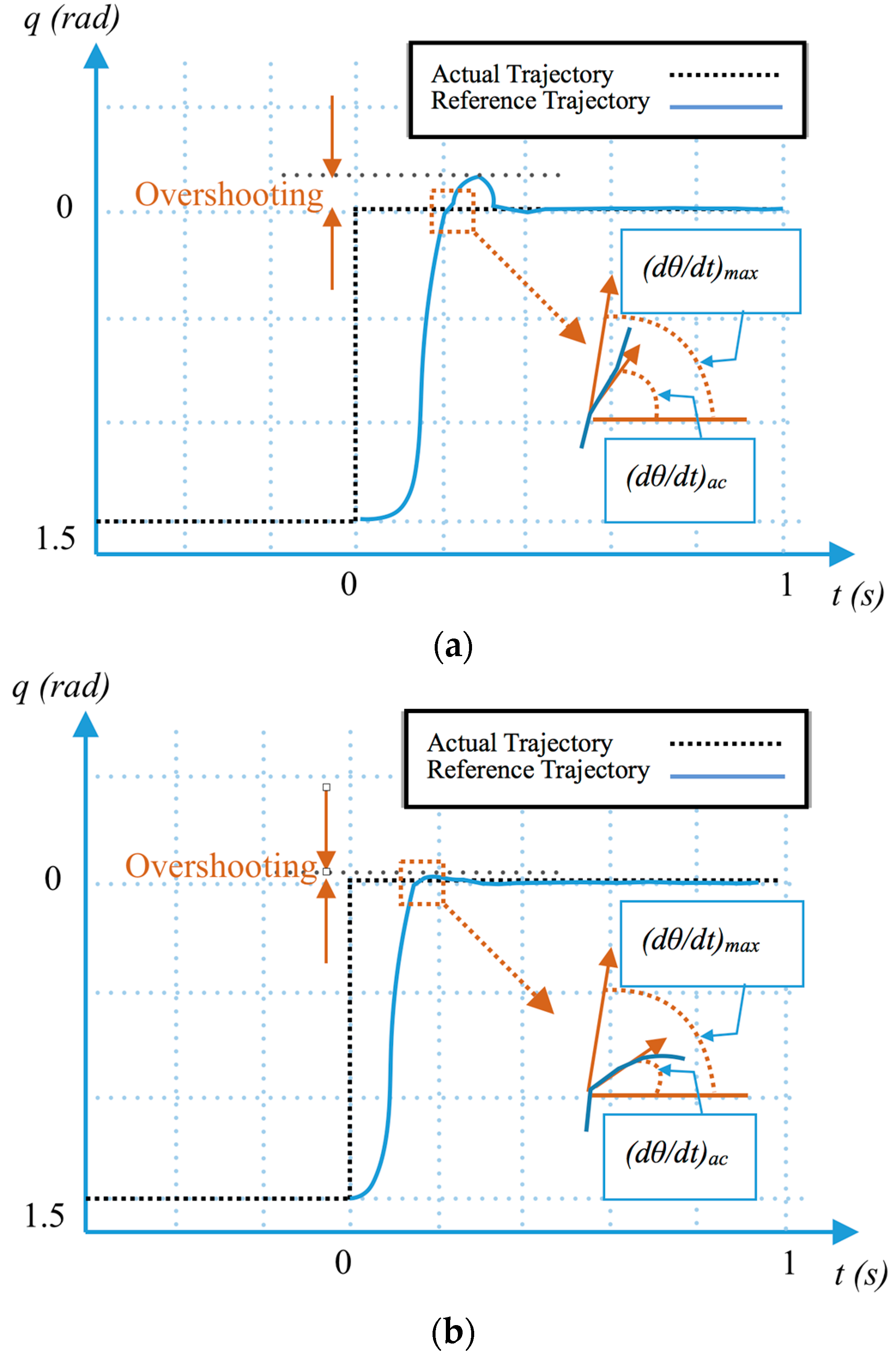
In order to show the over damping capability of MOD-AwAS, particularly at high stiffness, we set the position of the output link to a certain angle and manually pulled it away from its equilibrium configuration by 1.5 rad and released it. As a result of deflection, the link moved back to its equilibrium position. We record the link trajectory for three different stiffness values using its dedicated rotary encoder. Figure 7 shows the link trajectory for very low and low stiffness values of 35 Nm/rad and 50 Nm/rad, respectively.
The damping scale, DS, as defined by Equation (14), is the ratio of the link maximum velocity right before it reaches its equilibrium position over its velocity right after that (Figure 6).
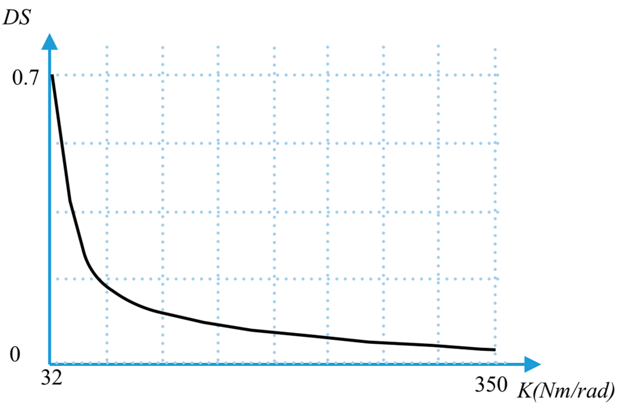
As Figure 7 makes clear, the DS parameter greatly decreases when the stiffness increases from K = 3 Nm/rad to K = 50 Nm/rad. We performed this experiment for different values of link stiffness and calculated the DS parameters in each case. Figure 8 shows the calculated DS parameter for different values of stiffness.
As shown in Figure 8, the DS parameter starts from 0.7 at minimum stiffness. This DS ratio results in a little bit of overshooting as illustrated in Figure 6. However, by increasing the stiffness, the DS parameter radically tends to zero. This implies the ability of MOD-AwAS to mechanically overdamp the oscillation around its equilibrium position.
4. Conclusions and Future Work
In this paper, we explained the design and development of MOD-AwAS. This novel actuator allows for adjustable stiffness and has the capability of mechanically overdamp the link oscillation, especially when the stiffness increases. MOD-AwAS employs a lever mechanism to regulate the stiffness. By changing the position of the pivot inside the lever, the stiffness of the output link can change from 32 Nm/rad to 350 Nm/rad in 0.2 s.
Since MOD-AwAS uses a lever mechanism with only one spring as compliant element, the output link can have full access to the energy storage capacity of the spring. This resulted in achieving a large range of deflection in a small size.
Using only one spring to regulate the stiffness brings an additional unique feature to MOD-AwAS, that is, discontinuity in the velocity as a result of an impact between lever and spring. This sudden change in the velocity greatly reduces the total energy of the link, which in turn forces the link to behave like an overdamped system.
The ability of MOD-AwAS in tracking a sine wave, as well as step trajectories, has been shown experimentally. Furthermore, the overdamping capability of MOD-AwAS has also been proven through calculating the damping scale parameter at different stiffness values.
As for future works, a multi-dof robotic arm from this actuator will be developed in order to explore the capability of MOD-AwAS in accurate pick and place tasks, as well as safely integrating with humans.
Acknowledgments
This work was supported by JSPS KAKENHI #26420201.
Author Contributions
Jae Hoon Lee designed and developed the proposed actuator. Christian Wahrmund designed the experimental setup and Amir Jafari perform the experiments and edited the paper.
Conflicts of Interest
Authors have no conflicts of interests.
References
- Schiavi, R.; Grioli, G.; Sen, S.; Bicchi, A. VSA-II: A Novel Prototype of Variable Stiffness Actuator for Safe and Performing Robots Interacting with Humans. In Proceedings of the 2008 IEEE International Conference on Robotics and Automation, Pasadena, CA, USA, 19–23 May 2008. [Google Scholar]
- Jafari, A.; Vanderborght, B.; Tsagarakis, N.; Cadwell, D. A Novel Actuator with Adjustable Stiffness (AwAS). In Proceedings of the 2010 IEEE/RSJ International Conference on Intelligent Robots and Systems, Taipei, Taiwan, 18–22 October 2010; pp. 4201–4206. [Google Scholar]
- Tsagarakis, N.G.; Sardellitti, I.; Caldwell, D.G. A New Variable Stiffness Actuator (CompAct-VSA): Design and Modelling. In Proceedings of the 2011 IEEE/RSJ International Conference on Intelligent Robots and Systems, San Francisco, CA, USA, 25–30 September 2011. [Google Scholar]
- Ketelaar, J.G.; Visser, L.C.; Stramigioli, S.; Carloni, R. Controller Design for a Bipedal Walking Robot Using Variable Stiffness Actuators. In Proceedings of the 2013 IEEE International Conference on Robotics and Automation, Karlsruhe, Germany, 6–10 May 2013. [Google Scholar]
- Kizilhan, H.; Baser, O.; Kilic, E.; Ulusoy, N. Comparison of Controllable Transmission Ratio Type Variable Stiffness Actuator with Antagonistic and Pre-Tension Type Actuators for the Joints Exoskeleton Robots. In Proceedings of the 2015 12th International Conference on Informatics in Control, Automation and Robotics (ICINCO), Colmar, France, 21–23 July 2015. [Google Scholar]
- Vu, H.Q.; Yu, X.; Iida, F.; Pfeifer, R. Improving Energy Efficiency of Hopping Locomotion by Using a Variable Stiffness Actuator. IEEE/ASME Trans. Mechatron. 2016, 21, 472–486. [Google Scholar] [CrossRef]
- Kim, B.S.; Song, J.B. Hybrid Dual Actuator Unit: A Design of a Variable Stiffness Actuator Based on an Adjustable Moment Arm Mechanism. In Proceedings of the 2010 IEEE International Conference on Robotics and Automation, Anchorage, AK, USA, 3–7 May 2010. [Google Scholar]
- Kim, B.S.; Kim, Y.L.; Song, J.B. Preliminary Experiments on Robotic Assembly Using a Hybrid-Type Variable Stiffness Actuator. In Proceedings of the 2011 IEEE/ASME International Conference on Advanced Intelligent Mechatronics (AIM), Budapest, Hungary, 3–7 July 2011. [Google Scholar]
- Berret, B.; Yung, I.; Nori, F. Open-Loop Stochastic Optimal Control of a Passive Noise-Rejection Variable Stiffness Actuator: Application to Unstable Tasks. In Proceedings of the 2013 IEEE/RSJ International Conference on Intelligent Robots and Systems, Tokyo, Japan, 3–7 November 2013. [Google Scholar]
- Vanderborght, B.; Albu-Schaeffer, A.; Bicchi, A.; Burdet, E.; Caldwell, D.G.; Carloni, R.; Catalano, M.; Eiberger, O.; Friedl, W.; Ganesh, G.; et al. Variable Impedance Actuators: A Review. Robot. Auton. Syst. 2013, 61, 1601–1614. [Google Scholar] [CrossRef]
- Romano, F.; Fiorio, L.; Sandini, G.; Nori, F. Control of a Two-DoF Manipulator Equipped with a PNR-Variable Stiffness Actuator. In Proceedings of the 2014 IEEE International Symposium on Intelligent Control (ISIC), Juan Les Pins, France, 8–10 October 2014. [Google Scholar]
- Penzlin, B.; Liu, L.; Leonhardt, S.; Misgeld, B. Torque Estimation in Variable Stiffness Actuators. In Proceedings of the 2016 International Conference on Systems Informatics, Modelling and Simulation (SIMS), Riga, Latvia, 1–3 June 2016. [Google Scholar]
- Barrett, E.; Fumagalli, M.; Carloni, R. Elastic Energy Storage in Leaf Springs for a Lever-Arm Based Variable Stiffness Actuator. In Proceedings of the 2016 IEEE/RSJ International Conference on Intelligent Robots and Systems (IROS), Daejeon, Korea, 9–14 October 2016. [Google Scholar]
- Visser, L.C.; Carloni, R.; Klijnstra, F.; Stramigioli, S. A Prototype of a Novel Energy Efficient Variable Stiffness Actuator. In Proceedings of the 2010 Annual International Conference of the IEEE Engineering in Medicine and Biology, Buenos Aires, Argentina, 31 August–4 September 2010. [Google Scholar]
- Carloni, R.; Marconi, L. Limit Cycles and Stiffness Control with Variable Stiffness Actuators. In Proceedings of the 2012 IEEE/RSJ International Conference on Intelligent Robots and Systems, Vilamoura, Portugal, 7–12 October 2012. [Google Scholar]
- Huang, T.H.; Kuan, J.Y.; Huang, H.P. Design of a New Variable Stiffness Actuator and Application for Assistive Exercise Control. In Proceedings of the 2011 IEEE/RSJ International Conference on Intelligent Robots and Systems, San Francisco, CA, USA, 25–30 September 2011. [Google Scholar]
- Bacek, T.; Unal, R.; Moltedo, M.; Junius, K.; Cuypers, H.; Vanderborght, B.; Lefe, D. Conceptual Design of a Novel Variable Stiffness Actuator for Use in Lower Limb Exoskeletons. In Proceedings of the 2015 IEEE International Conference on Rehabilitation Robotics (ICORR), Singapore, 11–14 August 2015. [Google Scholar]
- Cui, Z.; Cui, Y.; Qian, D.; Song, W.; Li, Y. Simulation Research and Experimental Verification of a Variable Stiffness Actuator with Automatic Rigidity/Compliance Switching. In Proceedings of the 2015 IEEE International Conference on Robotics and Biomimetics (ROBIO), Zhuhai, China, 6–9 December 2015. [Google Scholar]
- Tonietti, G.; Schiavi, R.; Bicchi, A. Design and Control of a Variable Stiffness Actuator for Safe and Fast Physical Human/Robot Interaction. In Proceedings of the 2005 IEEE International Conference on Robotics and Automation, Barcelona, Spain, 18–22 April 2005. [Google Scholar]
- Sunghoi, H.; Tonietti, G.; Bicchi, A. Neural Network Based Robust Adaptive Control for a Variable Stiffness Actuator. In Proceedings of the 2008 16th Mediterranean Conference on Control and Automation, Ajaccio, France, 25–27 June 2008. [Google Scholar]
- Sardellitti, I.; Medrano-Cerda, G.; Tsagarakis, N.G.; Jafari, A.; Caldwell, D.G. A Position and Stiffness Control Strategy for Variable Stiffness Actuators. In Proceedings of the 2012 IEEE International Conference on Robotics and Automation, Saint Paul, MN, USA, 14–18 May 2012. [Google Scholar]
- Sardellitti, I.; Medrano-Cerda, G.; Tsagarakis, N.G.; Jafari, A.; Caldwell, D.G. Gain Scheduling Control for a Class of Variable Stiffness Actuators Based on Lever Mechanisms. IEEE Trans. Robot. 2013, 29, 791–798. [Google Scholar] [CrossRef]
- Macnard, T.; Grioli, G.; Bicchi, A. A Real Time Robust Observer for an Agonist-Antagonist Variable Stiffness Actuator. In Proceedings of the 2013 IEEE International Conference on Robotics and Automation, Karlsruhe, Germany, 6–10 May 2013. [Google Scholar]
- Popov, D.; Gaponov, I.; Ryu, J.H. Towards Variable Stiffness Control of Antagonistic Twisted String Actuators. In Proceedings of the 2014 IEEE/RSJ International Conference on Intelligent Robots and Systems, Chicago, IL, USA, 14–18 September 2014. [Google Scholar]
- Macnard, T.; Grioli, G.; Bicchi, A. A Stiffness Estimator for Agonistic-Antagonistic Variable-Stiffness-Actuator Devices. IEEE Trans. Robot. 2014, 30, 1269–1278. [Google Scholar]
- Shintake, J.; Schubert, B.; Rosset, S.; Shea, H.; Floreano, D. Variable Stiffness Actuator for Soft Robotics Using Dielectric Elastomer and Low-Melting-Point Alloy. In Proceedings of the 2015 IEEE/RSJ International Conference on Intelligent Robots and Systems (IROS), Hamburg, Germany, 28 September–2 October 2015. [Google Scholar]
- Schimmels, J.M.; Garces, D.R. The Arched Flexure VSA: A Compact Variable Stiffness Actuator with Large Stiffness Range. In Proceedings of the 2015 IEEE International Conference on Robotics and Automation (ICRA), Seattle, WA, USA, 26–30 May 2015. [Google Scholar]
- Jafari, A.; Tsagarakis, N.G.; Caldwell, D.G. AwAS-II: A New Actuator with Adjustable Stiffness Based on the Novel Principle of Adaptable Pivot Point and Variable Lever Ratio. In Proceedings of the 2011 IEEE International Conference on Robotics and Automation, Shanghai, China, 9–13 May 2011. [Google Scholar]
- Jafari, A.; Tsagarakis, N.G.; Sardellitti, I.; Caldwell, D.G. How Design can Affect the Energy Required to Regulate the Stiffness in Variable Stiffness Actuators. In Proceedings of the 2012 IEEE International Conference on Robotics and Automation, Saint Paul, MN, USA, 14–18 May 2012. [Google Scholar]
- Kim, B.S.; Song, J.B. Design and Control of a Variable Stiffness Actuator Based on Adjustable Moment Arm. IEEE Trans. Robot. 2012, 28, 1145–1151. [Google Scholar]
- Jafari, A.; Tsagarakis, N.G.; Caldwell, D.G. A Novel Intrinsically Energy Efficient Actuator with Adjustable Stiffness (AwAS). IEEE/ASME Trans. Mechatron. 2013, 18, 355–365. [Google Scholar] [CrossRef]
Figure 1.
Prototype of the mechanically overdamped actuator with adjustable stiffness (MOD-AwAS).

Figure 2.
Schematic of stiffness adjustment principle. The lever and rotary spring with stiffness K are concentrically placed while they are unidirectionally attached at their leg sides. The pivot can travel inside the lever. (a) shows equilibrium configuration, while in (b) the lever is deflected due to the applied force F by angle θ.
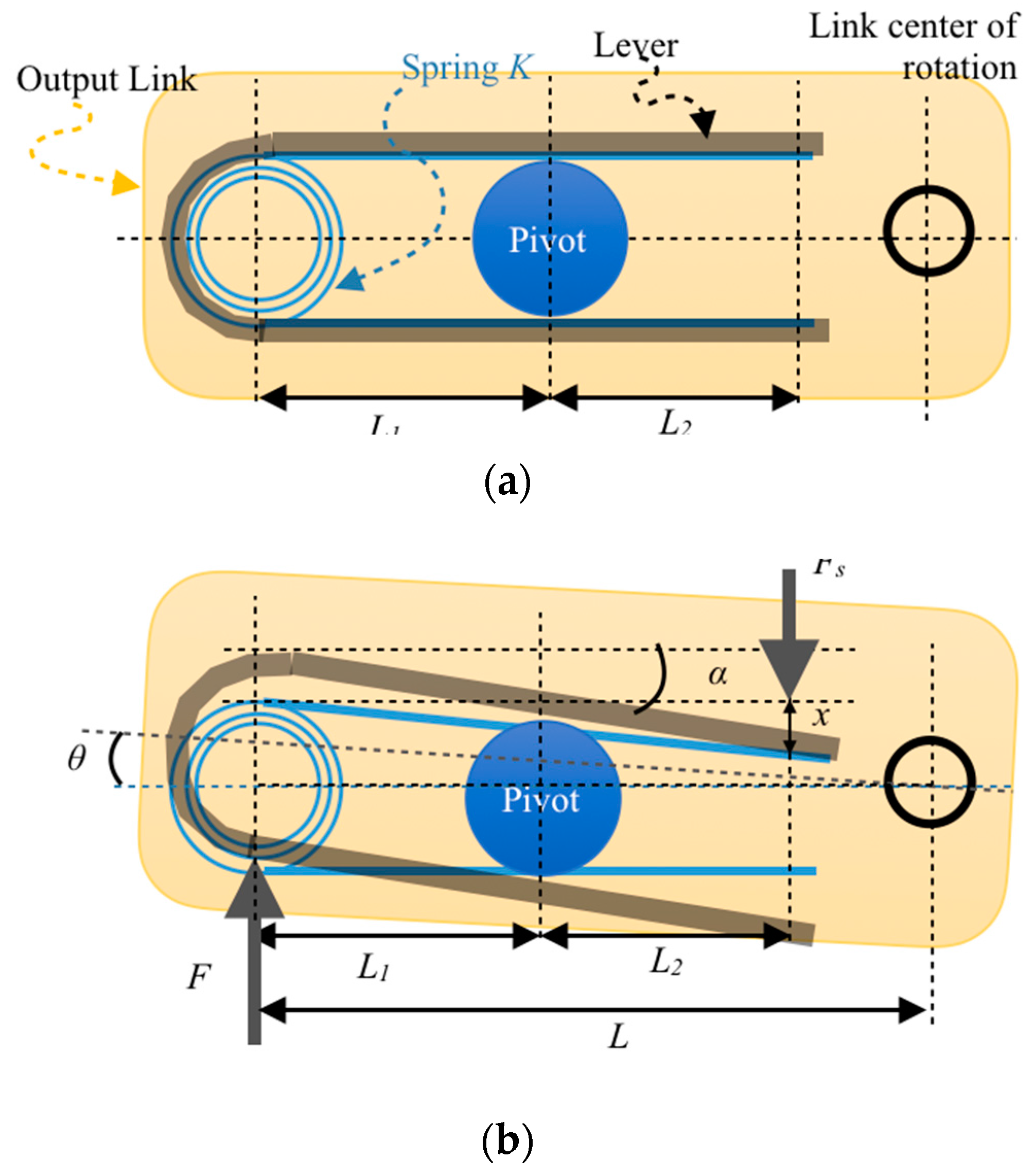
Figure 3.
Two halves of the stiffness adjustment mechanism of MOD-AwAS.
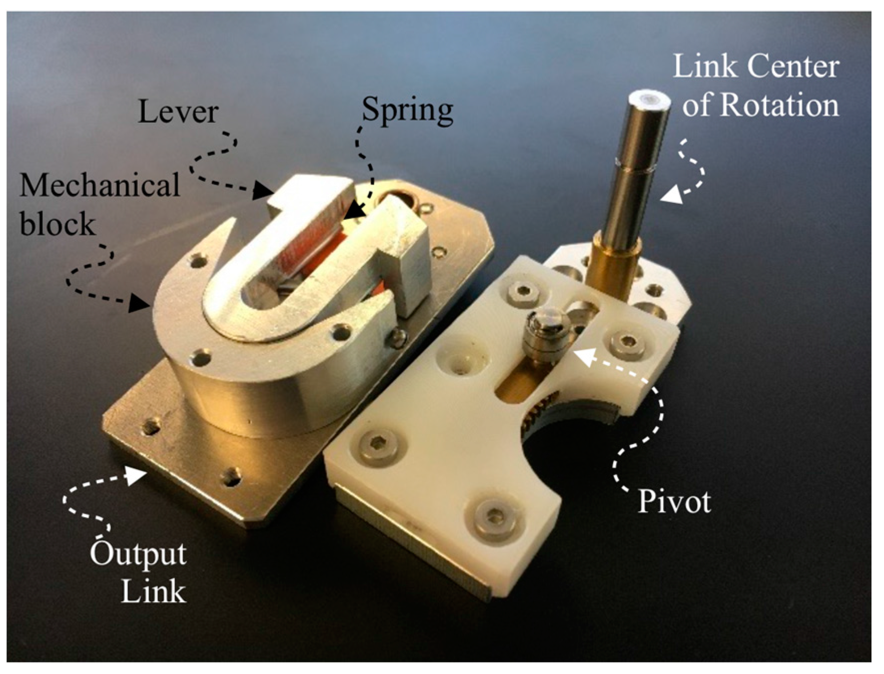
Figure 4.
Actual stiffness vs. estimated stiffness for MOD-AwAS.

Figure 5.
Tracking a sine wave trajectory; very low stiffness K = 35 Nm/rad (a); low stiffness K = 50 Nm/rad (b); and high stiffness K = 300 Nm/rad (c).
Figure 5.
Tracking a sine wave trajectory; very low stiffness K = 35 Nm/rad (a); low stiffness K = 50 Nm/rad (b); and high stiffness K = 300 Nm/rad (c).

Figure 6.
Output link is tracking a sine wave trajectory (a) while the stiffness is changing on-line following the sinusoidal trajectory from very low stiffness K = 35 Nm/rad to high stiffness K = 300 Nm/rad with 4 Hz frequency (b).
Figure 6.
Output link is tracking a sine wave trajectory (a) while the stiffness is changing on-line following the sinusoidal trajectory from very low stiffness K = 35 Nm/rad to high stiffness K = 300 Nm/rad with 4 Hz frequency (b).


Figure 7.
Trajectory of the link while it is manually deflected by 1.5 rad and reaches its equilibrium position at 0 rad, K = 35 Nm/rad (a) and K = 50 Nm/rad (b).
Figure 7.
Trajectory of the link while it is manually deflected by 1.5 rad and reaches its equilibrium position at 0 rad, K = 35 Nm/rad (a) and K = 50 Nm/rad (b).

Figure 8.
Damping scale (DS) for different link stiffness.


Table 1.
Physical specification of MOD-AwAS.
| Specification | Value | Specification | Value |
|---|---|---|---|
| Height | 10 cm | Length | 50 cm |
| Width | 10 cm | Weight | 200 g |
| Min. Stiffness | 32 Nm/rad | Rotation Range (Min. Stiffness) | +/−0.3 rad |
| Max. Stiffness | 350 Nm/rad | Rotation Range (Max. Stiffness) | +/−0.3 rad |
| Min. Deflection (Min. Stiffness) | 0.2 rad | Max. Torque | 3.2 Nm |
| Max. Deflection (Max. Stiffness) | 0.15 rad | Max. Velocity | 0.5 rad/s |
© 2017 by the authors. Licensee MDPI, Basel, Switzerland. This article is an open access article distributed under the terms and conditions of the Creative Commons Attribution (CC BY) license (http://creativecommons.org/licenses/by/4.0/).
Share and Cite
MDPI and ACS Style
Lee, J.H.; Wahrmund, C.; Jafari, A. A Novel Mechanically Overdamped Actuator with Adjustable Stiffness (MOD-AwAS) for Safe Interaction and Accurate Positioning. Actuators 2017, 6, 22. https://doi.org/10.3390/act6030022
AMA Style
Lee JH, Wahrmund C, Jafari A. A Novel Mechanically Overdamped Actuator with Adjustable Stiffness (MOD-AwAS) for Safe Interaction and Accurate Positioning. Actuators. 2017; 6(3):22. https://doi.org/10.3390/act6030022
Chicago/Turabian StyleLee, Jae Hoon, Christian Wahrmund, and Amir Jafari. 2017. "A Novel Mechanically Overdamped Actuator with Adjustable Stiffness (MOD-AwAS) for Safe Interaction and Accurate Positioning" Actuators 6, no. 3: 22. https://doi.org/10.3390/act6030022
Note that from the first issue of 2016, this journal uses article numbers instead of page numbers. See further details here.