Generalization of Series Elastic Actuator Configurations and Dynamic Behavior Comparison


Department of Robotics Engineering, DGIST (Daegu Gyeongbuk Institute of Science and Technology), Daegu 42988, Korea
*
Author to whom correspondence should be addressed.
†
These authors contributed equally to this work.
Actuators 2017, 6(3), 26; https://doi.org/10.3390/act6030026
Submission received: 1 May 2017
/
Revised: 30 July 2017
/
Accepted: 15 August 2017
/
Published: 22 August 2017
(This article belongs to the Special Issue Variable Stiffness and Variable Impedance Actuators)
Abstract
:The Series Elastic Actuator (SEA) has recently been developed by many research groups and applied in various fields. As SEA is the combination of motor, spring, gear and load, various types and configurations of mechanism have been developed as SEAs to satisfy many requirements necessary for the applications. This paper provides a theoretical framework to categorize and compare these various configurations of SEAs. The general structure and model of SEA is provided, and SEA configurations are categorized into Force-sensing Series Elastic Actuator, Reaction Force-sensing Series Elastic Actuator and Transmitted Force-sensing Series Elastic Actuator, based on the relative location of the spring. Criteria such as Force sensitivity, Compliance and Transmissibility of SEA are derived and compared using actual SEAs that have been developed previously.
1. Introduction
Series Elastic Actuator (SEA), a type of Variable Impedance Actuator (VIA), is an actuator which receives much attention as the next-generation actuator [1]. Since it was first introduced in 1995, SEA has been currently recognized in the robotics field as an actuator system to implement a high-performance torque control [2].
In contrast to the conventional actuation, which contains rigid gears that transmit the force/torque to the load which is proportional to the motor torque, which is also proportional to the current flowing through it. On the other hand, the torque transmitted to the end load by an SEA, is supposed to be proportional to the deformation of the spring, which is a key component of an SEA. In other words, the SEA changes the torque generation problem from the motor current decision problem to the spring deformation decision problem, due to the presence of the spring. In addition to this force/torque generation characteristic, SEA is well-known for its complicated mechanism, as it is a combination of a motor, gears and a compliant component, the structure of which depends on the configuration of each SEA.
Despite these difficulties, SEA has been applied to robotic applications in various fields to take advantage of the high fidelity force control of SEA [3,4,5,6,7,8,9,10,11,12]. Lots of applications of SEA for quadruped robots, biped robot, dual arm robots and wearable robots, have demonstrated that SEA is the promising actuator system.
Even with these many successful developments of SEAs, there have been few trials to understand and analyze SEA in a generalized framework, so that various types of SEAs should be assessed and compared in terms of same standards.
Figure 1 shows various types of SEAs, that can be categorized in terms of the transmission type and movement type.
This categorization is rather a kinematic categorization than a dynamic categorization, which can be utilized to represent and compare the output motions of SEA. Dynamic performance of SEA, however, cannot be compared or categorized using this standard. This dynamic categorization of SEA needs to provide some insights and criteria of dynamic characteristics of SEAs, which can be reflected in the design of SEA mechanism and controllers.
As the result of this demand, in the article of [1], the Variable Impedance Actuator (VIA) including the Variable Stiffness Actuator, which is the upper level concept of SEA, is categorized its structural characteristics, and its advantages and disadvantages are identified based on the categorization. Although this study mentioned SEA, one of the types of VIA, it did not discuss the classification of SEA structures and assessments.
Another similar approach is proposed in [20], which categorizes SEA in terms of the design methodology to generate variable impedance using two motors. Tagliamonte et al. [21] attempted to numerically compare the performance of a double actuated VIA in terms of the metric of “power/mass” or “power/volume” depending on the position of the spring. Lauria et al. [22] discussed implementation methodology to incorporate differential gears in SEA. All these studies to provide a framework to distinguish and assess the structure of SEA. Nevertheless, there has not been a criteria that is fully based on the dynamic characteristics of SEA, and thus it can be utilized for the analysis and design of SEA mechanism and controller.
This paper proposes a novel categorization of SEA in terms of the displacement of the spring and the gear in SEA. SEA is classified into three types according to the relative position of the spring with regard to the gear: Force-sensing Series Elastic Actuator (FSEA) which locates the spring after the transmission gear, Reaction Force-sensing Series Elastic Actuator (RFSEA) which locates the spring before the transmission gear and Transmitted Force-sensing Series Elastic Actuator (TFSEA) which locates the spring inside the transmission gear. Such a structural difference may lead to a practical challenge of determining the placement, attachment, and type of the encoder to measure the deformation of the spring. However, the problems are hard to be generalized since it is highly dependent on the type of application. Therefore, considering general aspects even excluding these practical problems, the dynamic characteristics of all the SEA types are thoroughly derived and validated through experiments in this paper. In order to represent all three types of SEA, a generalized dynamic model of SEA is derived, which can give some insight of the design of SEA by providing a common framework to inspect dynamic characteristics of various SEA structures.
The organization of this paper is illustrated in Figure 2. Section 2 introduces a new viewpoint of the structure of SEAs and categorizes SEAs that have been proposed in previous studies into three types based on the proposed viewpoint. In Section 3, the dynamics of three types of SEA, which are Force-sensing Series Elastic Actuator, Reaction Force-sensing Series Elastic Actuator and Transmitted Force-sensing Series Elastic Actuator are derived, and a generalized dynamic model is proposed. In Section 4, three assessment criteria, which are defined as the required dynamic characteristic for SEA are proposed, and three types of SEA are compared using the proposed criteria. Finally, Section 6 summarizes the contributions of this paper.
2. Three Types of SEA Configurations
Paine et al. [13] categorizes SEA into Force-sensing SEA (FSEA) and Reaction Force-sensing SEA (RFSEA) depending on the location of the spring; the spring is located after the reduction gear and before the load in FSEA while the spring is located before the reduction gear in RFSEA. In this section, SEA configuration is categorized in terms of relative location of the spring.
2.1. Categorization Based on Spring Location of SEA
In general, a rigid actuator system can be illustrated as Figure 3a: force/torque is generated from a power source (a motor in this case) and is transmitted to the load through a transmission (a reduction gear in this case) while being amplified. The transmission usually does not provide back-drivability, which causes non-transparency in the rigid actuator system; the torque generated from the power sources can be transmitted to the load with high efficiency, while the force coming from the load cannot be transmitted to the power source side. In order to solve this problem, SEA have been proposed in which a compliant component is incorporated to precisely measure/control the interaction force of the load side.
The compliant component (usually spring) is incorporated in SEA to realize high fidelity force control. The location of the spring, however, can differ (any place among the power source, the transmission and the load) leading to various configurations of SEA. Figure 3b illustrates the possible locations (1), (2), (3) and (4) of the spring in SEA. Since the SEA structure was firstly proposed by Pratt in 1995, many types of SEA have adopted the configuration in which the spring is positioned at (4). Recently, however, novel SEAs have been proposed to have different configurations by arranging springs at various positions from (1) to (3). This paper categorizes SEA configuration into three types based on the position of the spring as follows.
- Reaction Force-sensing Series Elastic Actuator (RFSEA)—spring located at (1) or (2), before the transmission
- Transmitted Force-sensing Series Elastic Actuator (TFSEA)—spring located at (3), inside the transmission
- Force-sensing Series Elastic Actuator (FSEA)—spring located at (4), after the transmission
Note that any type of transmission can be applied in these configuration, which means the proposed categorization is general enough. SEA in [22], which also utilized the spring gear relationship. However, the study proposed only the categorization without providing dynamic analysis of each configuration. This paper starts from the categorization and extends it to dynamics analysis and novel criteria. The detail of three SEA configurations, FSEA, RFSEA and TFSEA, are discussed in detail in the subsections that follow.
2.2. Force-Sensing Series Elastic Actuator (FSEA)
FSEA, is a SEA which combines a motor, a reduction gear, a spring and a load in this order so that the spring can directly measure the force from the load. This structure, which was proposed as the structure of the initial SEA, has been adopted as the configuration of many SEA designs. In the Figure 4, the detail of FSEA configuration is illustrated, where the motor stator is attached to ground to provide absolute force to the transmission, and the amplified force by the transmission drives the spring deformation to generate spring force/torque. In other words, the force/torque output of SEA is the spring torque, which can be controlled by the motor torque. Notice that the external force from the load side can directly affect the spring deformation too.
For the force measurement, the spring displacement should be measured. In the case of most FSEA applications, the motor angle and the load side angle are measured using sensors such as encoders, and the spring deformation is derived based on the two measurements. Then the force can be calculated by multiplying the spring deformation and the stiffness coefficient.
According to [13], this structure can be easily implemented through an intuitive design method, and the impact force can be low-pass filtered through the spring in the event of an external impact to safely protect the transmission. However, the size of whole actuator (i.e., length of SEA) increases due to the series structure.
Figure 5a is the first SEA proposed in [2], the configuration of which has been adopted as a general structure in most of the early SEAs. The SEA configuration proposed in [14] can also be categorized into FSEA, where a worm gear was utilized as the transmission and a rotary spring is utilized as the compliant element.
2.3. Reaction Force-Sensing Series Elastic Actuator (RFSEA)
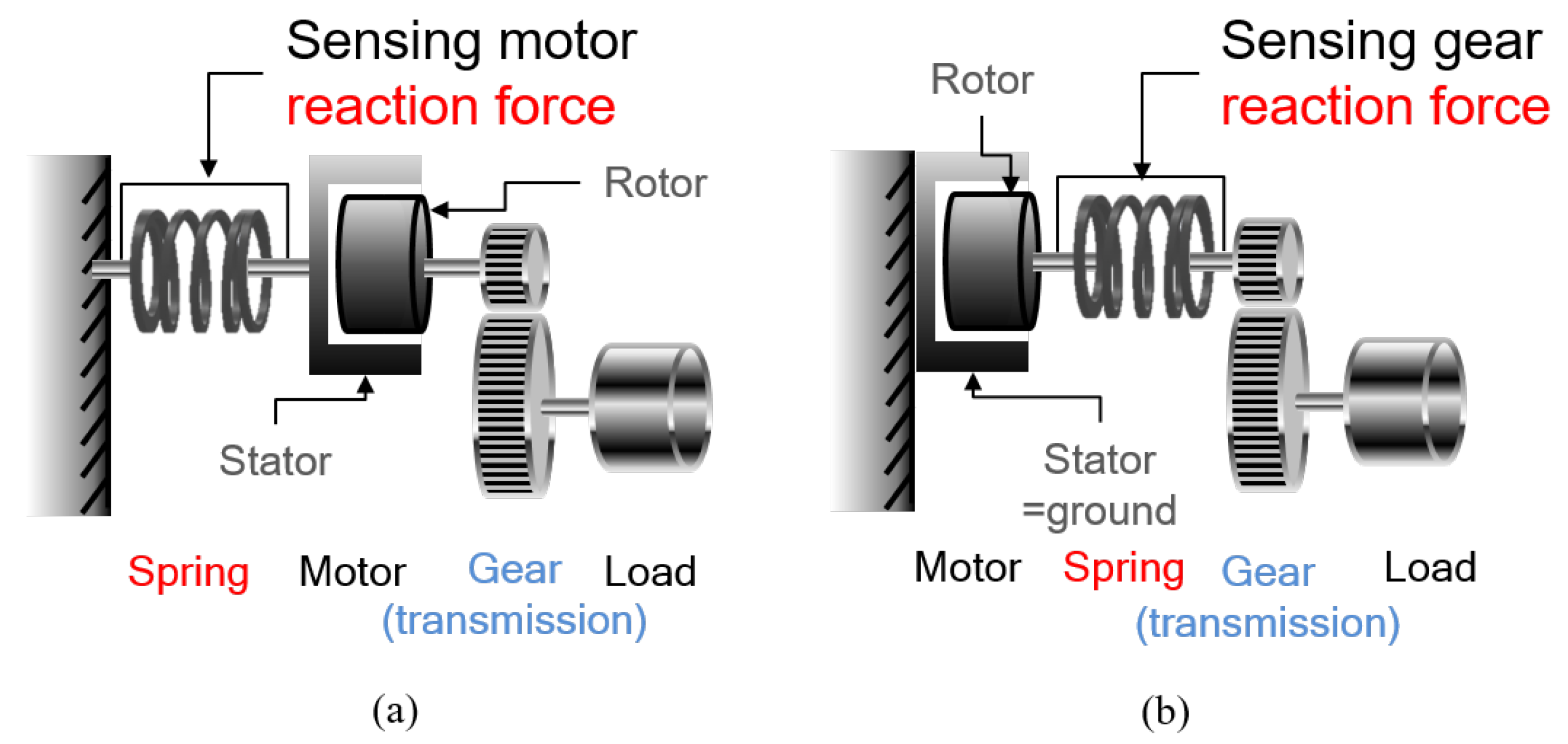
RFSEA locates the spring before the transmission, which can be divided into two types as illustrated as shown in Figure 6.
The spring can be placed between the ground and the motor stator. The motor generates a relative torque between the stator and the rotor, and the motor torque is amplified by the transmission and directly transferred to the load. In RFSEA in Figure 6a, the spring deformation is proportional to the reaction force of the motor with respect to the ground. Position sensors can be implemented in the motor and the spring.
Figure 6b describes another type of RFSEA, where the spring is placed between the motor rotor and the transmission.In this case, spring deflection measures the direct motor torque and the reduced external torque.
Both cases can be considered as RFSEA because the reaction force that occurs before transmission can be measured during driving. The dynamic characteristics, however, of two types are different: the inertia of the motor stator should be taken into account in Figure 6a, since it is not fixed as in Figure 6b and generates inertial force/torque.
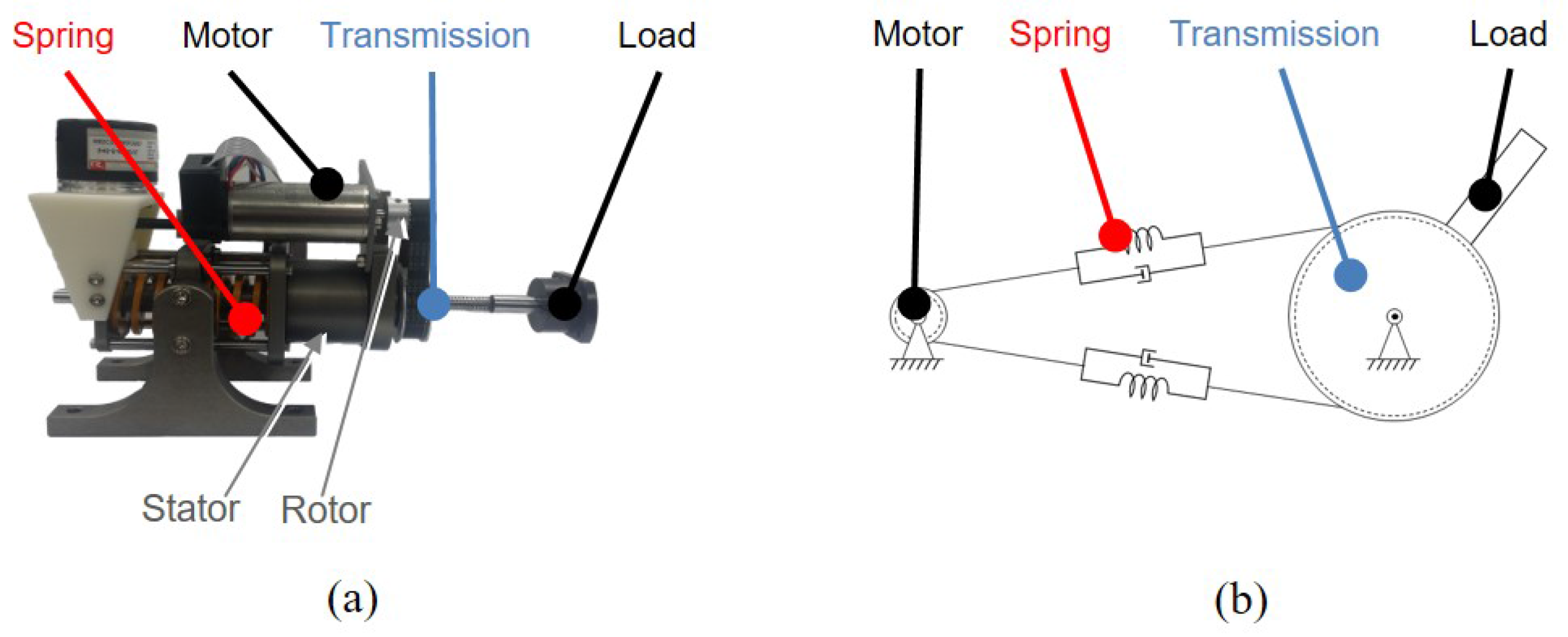
The UT-SEA shown in Figure 7a was developed as the first RFSEA in [13]. This mechanism used a ballscrew to create a prismatic motion using a rotating motor, and the RFSEA structure of the Figure 6a was realized by mounting a compression spring on the motor stator.
The another type of RFSEA which is called MARIONET (Moment arm Adjustment for Remote Induction Of Net Effective Torque) was proposed in [19] as in Figure 7b, which utilized the wire driven transmission with pulley. MARIONET has the structure as shown in Figure 6b, where the motor is fixed to the base and the elastic element is inserted before the pulley of the end-link.
2.4. Transmitted Force-Sensing Series Elastic Actuator (TFSEA)
TFSEA is defined as SEA which places a spring inside the transmission. TFSEA also can be divided into two types of implementations as described in Figure 8.
Figure 8a describes a TFSEA configuration in which the spring is located between the transmission gears, so that it can measure the transmitting torque inside the gears.
Figure 8b describes a TFSEA configuration, where a differential gear such as a planetary gear and Harmonic Drive is utilized as the compliant component. The motor torque is transmitted to the load, through the differential gear in this configuration. The spring is attached to the gear housing that is connected to the differential gear, so that the torque transmitting the gear can be measured by the spring. The position sensors can be attached to the motor and spring in this configuration. Notice that the inertia of the gear housing should be taken into consideration in the case of Figure 8b.
DEA (Differential Elastic Actuator) shown in Figure 9a can be categorized as TFSEA which utilized a Harmonic Drive as a differential transmission [22]. A hollow motor is utilized to deliver the torque to the wave generator of Harmonic Drive, and this torque is captured as the transmitting torque by the spring connected between the flex spline and the ground.
cPEA (Compact Planetary-geared Elastic Actuator) is another TFSEA that employed a planetary gear as the differential transmission [15]. The motor torque is transmitted from the sun gear to the carrier that is connected to the load. The transmitting torque is measured by a spring that is connected between the ring gear and the ground. In [15], the dynamics of cPEA was accurately obtained and utilized in the model-based force control.
3. Generalized Dynamic Model for SEA Configurations
The dynamics of the SEA needs to be derived for the design and analysis of the controller. As the structure of SEA is composed of various components, the dynamics of each component is coupled with each other in various ways, which makes the derivation of the SEA dynamics complicated.
The dynamics of SEA has been studied using several models. However, those studies are inconsistent with each other, and thus fail to provide a comprehensive dynamic model and insights on SEA dynamics in general. This also makes it difficult to make a reasonable dynamic characteristics comparison among different configurations of SEA.
In order to address this issue, this paper investigates the dynamics of three types of SEA, and then proposes a generalized dynamic model that can be applied to all the SEA configurations. The proposed generalized dynamic model can be utilized as a framework where various configurations of SEA can be integrated and compared consistently.
The proposed generalized dynamic model of SEA is derived and validated through the following process.
- The following three different SEAs are selected as representatives of the proposed three SEA configurations, and dynamic model of each SEA is examined.
- A generalized dynamic model is proposed, and it is shown that all the SEAs with the different SEA configurations can be modeled using the generalized dynamic model.
- Transfer functions of SEA (from the motor torque to the load angle, from the motor torque to the spring deformation and so on) are derived using the derived dynamic model.
- The derived dynamic model is verified through the comparison with frequency response function measurements.
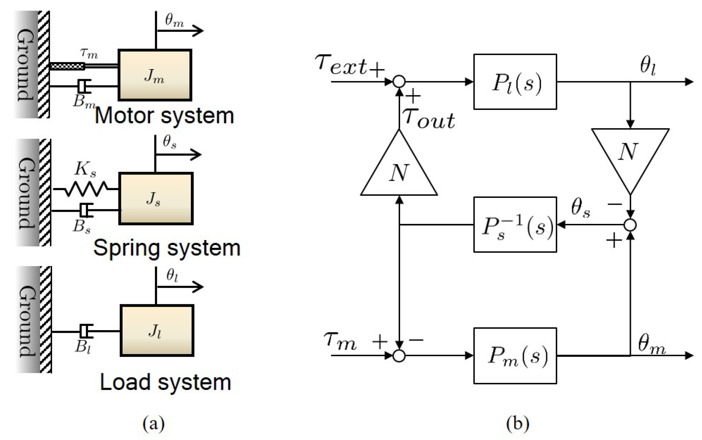
3.1. Dynamic Model of cRSEA
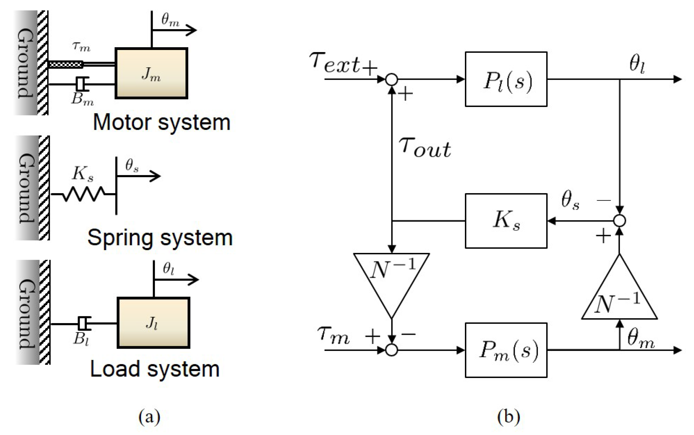
SEA is basically a flexible system consisting of two masses, and [23] has thoroughly investigated the dynamics of SEA using the two-mass dynamic model. The two-mass dynamic model can be interpreted as the combination of three kinds of free-body dynamics as illustrated in Figure 10a. The free-body dynamics of FSEA consists of:
- The motor system dynamics , which is composed of the inertia and the damping coefficient of the rotor of the motor including the worm gear inertia,
- The load system dynamics , which contains the end-link of FSEA with load inertia and damping coefficient ,
- The stiffness coefficient of the spring , which connects two systems (i.e., and ) relatively.
In this system, the angle of the motor is defined as , the angle of the load as and the spring deformation as . The governing equation of each system can be expressed as follows.
where is the force generated by the motor from the ground, is the force generated by the spring deformation, and is the external force applied from the environment to the load side of FSEA.
Each system can be expressed as , and by Laplace transformation the Equations (1)–(3), respectively. The three free-body dynamic systems are under kinematic constraints via gear, the gear ratio which is given as N. The constraint condition is expressed as:
Notice that FSEA is a Multi-Input Multi-Output (MIMO) system, which has multi input forces such as , and multi output angles such as , , and as shown in Figure 10b. The dynamic model, therefore, should be able express all these input and output features to describe its characteristics precisely. Figure 10b is the two-mass model to describe the dynamic characteristic of FSEA, and the transfer functions from the force inputs to the angle outputs are summarized in Table 1.
3.2. Dynamic Model of RFSEA
The dynamic model of RFSEA has been analyzed based on three inertias in [24], can be interpreted as three combinations of three free-body dynamics as illustrated in Figure 10a. The free-body dynamics of RFSEA consists of:
- The motor system dynamics , which is composed of the inertia and the damping coefficient of the rotor of the motor including the timing pulley inertia,
- The load system dynamics , which contains the end-link and the ball screw of RFSEA with load inertia and damping coefficient ,
- The spring system dynamics , which has the stiffness coefficient of the spring connecting the stator of the motor and the ground as well as the inertia of the stator and the damping coefficient .
Note that the RFSEA configuration analyzed here is the motor reaction force sensing type one, which has the spring inertia and damping . Figure 11 shows the schematic of free-body dynamics of RFSEA; it consists of three free bodies, the motor system, the load system and the spring system. and are the dynamic characteristics of the spring system which is represented as the blue colored section.
In the same way as FSEA, the angle of the motor is defined as , the angle of the load as and the spring deformation as , and the governing equation of each system can be expressed as follows.
where is the relative force generated by the motor between the rotor and the stator, is the force transmitted to the load from the spring and is the external force exerted on the end-link of RFSEA (i.e., end of ball screw shaft).
Each free-body dynamics of RFSEA can be expressed as , and by Laplace transformation of the Equations (5)–(7), respectively. Taking into consideration the gear ratio N of the ball-screw, the kinematic equation of , and can be obtained as follows.
3.3. Dynamic Model of TFSEA
Figure 13 illustrates the schematic of cPEA (compact Planetary geared Elastic Actuator), which is a TFSEA with a differential gear. The dynamics of this complicated TFSEA has been discussed in [15], and it also can be interpreted using the combination of three kinds of free-body dynamics.
Figure 14a illustrates the free-body dynamics of the TFSEA, which consists of:
- The motor system dynamics , which is composed of the inertia and the damping coefficient of the rotor of the motor including the sun gear inertia of planetary gear unit,
- The load system dynamics , which includes the carrier(to constraint planet gears) of the planetary gear unit with the load inertia and the damping coefficient ,
- The spring system dynamics , which has the stiffness coefficient which is also connected the ring gear that demonstrates the inertia and the damping .
Notice that the other end of the spring is connected to the ground to which the stator of the motor is also connected. and are attributed to the motion of the ring gear with regard to the ground. Figure 13 describes the mechanical parts corresponding each dynamic system, where the spring system is denoted as the blue colored body that is connected to the spring (the yellow part).
In cPEA, the angle of the sun gear is defined as , the angle of the carrier is defined as and the ring gear angle (spring deformation) is defined as . The governing equation of each systems can be expressed as follows.
where is the force generated by the motor, is the force transmitted to the load by the spring connected to the ring gear, is the external force applied to the carrier from outside environment.
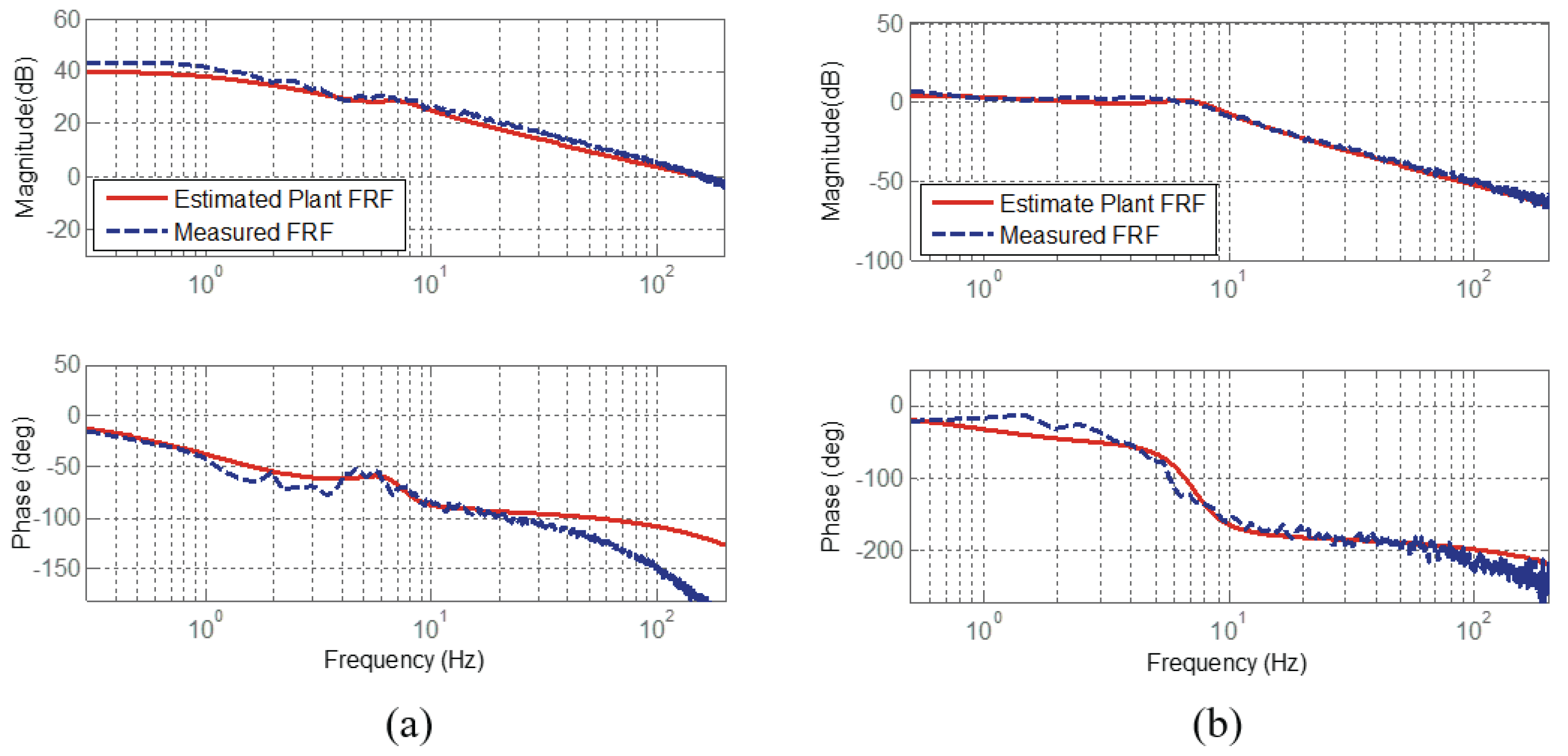
3.4. Validation of Derived Dynamic Models
In order to verify the dynamic models of all the SEA configurations discussed in Section 3.1, Section 3.2 and Section 3.3, the dynamic characteristics of the SEAs are measured as the Frequency Response Functions (FRFs) and compared with the derived dynamic model. In other words, the FRF of each SEA is measured using the inputs and outputs of SEA, and it is compared with the calculated FRF based on the derived dynamic model.
In Figure 15, Figure 16 and Figure 17, (a) describes FRF from the motor torque to the motor speed (in RFSEA, position); and (b) describes FRF from the motor torque to the spring deformation. The blue dotted-lines are the FRF measurements from the experiments, and the red-solid lines are the FRFs obtained from the dynamic models.
3.5. Generalized Dynamic Model of SEA as Dynamics Framework
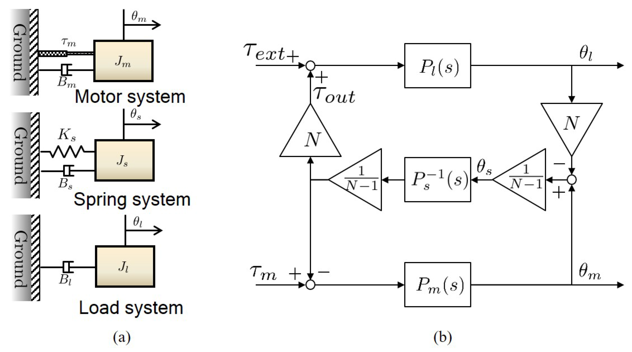
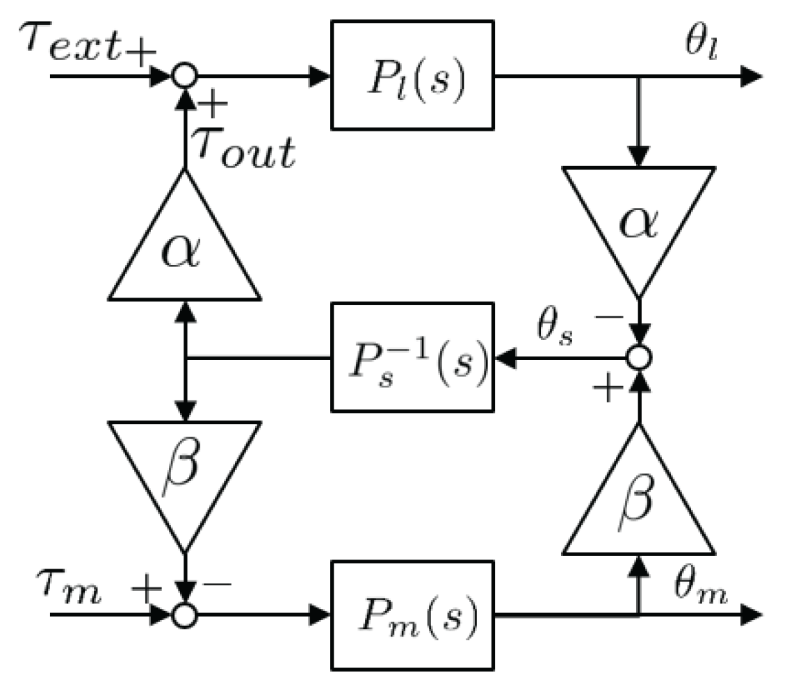
The investigation of the dynamics of all the SEA configurations has revealed that SEA has common structural characteristic; it consists of three dynamic system, i.e., the motor system, the load system and the spring system, and the transmissions combines the systems with any kind of kinematic constraint. A generalized block diagram that can express these features in general is described in the Figure 18. A further look at Figure 10b, Figure 12b and Figure 14b and comparison among them provide a comprehensive understanding of the general dynamic model of SEAs; the dynamic behavior of SEA consists of , and , and the coupling among them by the transmissions can be specified depending on the relative positions of the transmission and the spring.
In the generalized dynamic model Figure 18, generic gear ratio description alpha and beta are adopted, and general spring dynamics description is also adopted. Each , and for the case of cRSEA, RFSEA and cPEA is summarized in Table 4. Notice that any types of SEA configuration (even other more complicated configuration than cRSEA, RFSEA and cPEA) can be described by the proper combinations of , and . In other words, , and can characterize the dynamic behavior of SEAs, and thus should be designed with care to achieve any desired dynamic feature.
Transfer functions calculated from the generalized dynamic model can be utilized as mathematical tools to assess the dynamic behaviors of SEA in numerical ways. Table 5 is the transfer functions of the generalized dynamic model.
4. Assessment Criteria and Comparison of SEAs
Several studies to consider had sought to evaluate the performance of the compliant actuator. Tagliamonte et al. [21] attempted to numerically compare the performance of a double actuated VIA with the concept of “power/mass” or “power/volume” depending on the position of the spring. Robinson et al. [26] proposed a criteria of the Large Rorque Bandwidth (LTB) that can evaluate the performance under the large force command by using simple model of force-controlled SEA. In a similar study, Maximum Torque Transmissibility (MTT), which is the criterion for defining the maximum force generation performance from the viewpoint of velocity limitation, is presented by using the dynamics of FSEA under force control [27].
In this section, three criteria to represent the characteristics and performance of SEA are proposed using the proposed generalized dynamic model. The three SEA configurations are compared based on the proposed assessment criteria. An actuator system as an ideal force source is supposed to deliver accurate force to the load while it can react to any type of external forces sensitively and safely. This defines the requirements for SEA as: (1) the generation of accurate and efficient forces, and (2) the sensitive and safe response to external forces. One of the advantages of SEA, energy storing, is an important factor that should be considered as a criterion. However, by considering the governing equation of the spring potential energy, the energy storing characteristic depends on the behavior of the spring itself, not on the structural differences of SEA. Therefore, energy storage is not considered in this paper which mainly deals with the performance differences caused by the relative placement among the spring, the gearbox and the motor.
Three criteria are proposed to assess the ability of SEAs to meet these requirements.
- Force sensitivity—SEA should respond sensitively to external forces.
- Compliance—For the safety, it is necessary to react compliantly against the external force.
- Transmissibility—Torque transmission efficiency should be high.
Note that the meaning of the three criteria proposed in this paper is defined as the unique feature of SEA and is different from the physical meaning of words.
Section 4.1 discusses each criterion in detail, and Section 4.2, Section 4.3 and Section 4.4 examine and compare three types of SEA in terms of the proposed assessment criteria.
4.1. SEA Assessment Criteria
Using the generalized dynamic model proposed in Section 3, the required dynamic behaviors of SEA are defined in the forms of transfer functions, which can be evaluated in terms of magnitudes and phases in the frequency domain.
4.1.1. Force Sensitivity
Force sensitivity is the ability of SEA to accurately measure and control the force interacting with the external environment. SEA is basically an actuator system that measures the deformation of a spring and generates force based on it, when an external force is applied. Therefore, force sensitivity as an assessment criteria can be defined as how much the spring can be deformed with respect to external force. In other words, SEA with higher force sensitivity generates larger spring deformation when the same amount of external force is applied. Force sensitivity is related to the encoder resolution problem in practice; SEA with higher sensitivity can have higher force measurement resolution.
To quantify this force measurement and response characteristic, the force sensitivity is defined as the transfer function from external force to spring deformation given as
4.1.2. Compliance
In order to ensure safe interaction with the environments and to protect the transmission against the impacts, reaction force (i.e., mechanical impedance) of SEA against external force should be small. SEA is considered to present better safety than rigid actuators thanks to its compliant component. However, this characteristic needs to be assessed in a more quantitative way. Compliance can be defined as the transfer function from the external force to the velocity of the end link which can quantify the flexibility of SEA against the external force.
where .
4.1.3. Transmissibility
SEA also has a function of a transmission that converts the torque generated by the motor to the restoring torque of the spring. Transmissibility can be defined as the dynamic characteristic to express how the motor force is transmitted to the load side through the spring deformation. The high transmissibility represents the high efficiency of the SEA.
Transmissibility is defined as the transfer function from the motor torque to the output force of the SEA to quantify the characteristics of the force generation efficiency.
In the following subsections, the dynamic behaviors of three kinds of SEA are compared using the proposed assessment criteria. The values of the criteria for each SEA are calculated using MATLAB. The mechanical parameters of all the SEA to be compared are given in Table 6. Note that the simulation parameters used in this paper are set as one example to compare the three types of SEA in fair condition. From the assumption of this paper, especially with the same spring stiffness, the output stiffness of the three types of SEA can vary depending on the position of the reduction ratio.
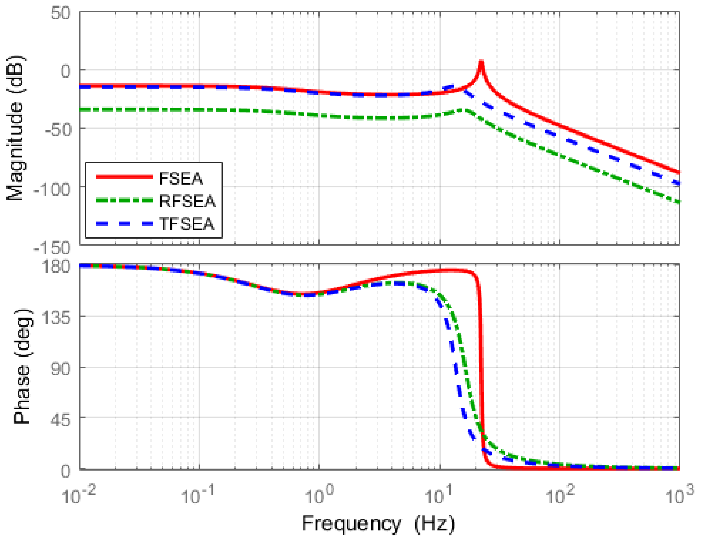
4.2. Force Sensitivity
The frequency responses of force sensitivity of all the SEAs are calculated and shown in Figure 19. The sensitivity of SEAs can be evaluated and compared on Figure 19.
The higher the force sensitivity magnitude is the larger the spring deformation occurs, even with the same amount of external force. The FSEA has the highest magnitude of force sensitivity in Figure 19 as the external force is directly transmitted to the spring without going through the transmission gear in the case of FSEA.
It can be also concluded from the result that encoders with high resolutions are needed to guarantee the force sensitivity in the case of RFSEA.
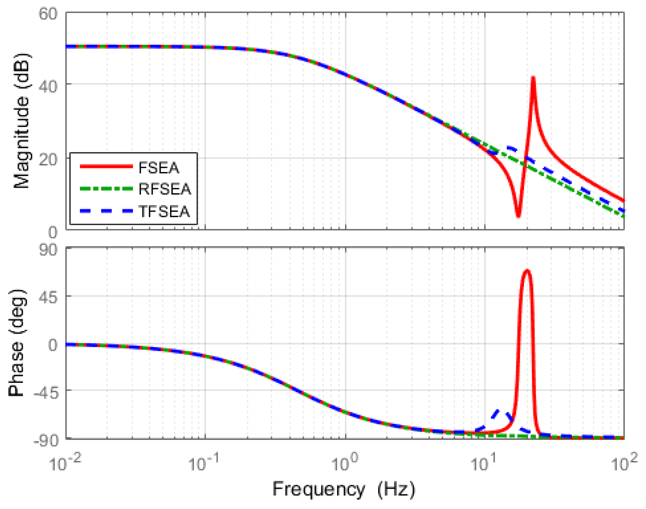
4.3. Compliance
Compliance of each SEA against the external force are calculated and shown in the Figure 20, and the compliance of each SEA can be evaluated and compared in the frequency domain using Figure 20.
Compliance of the three SEAs shows a similar response in the lower frequency range in Figure 20. Resonant and anti-resonant characteristics appear in certain frequencies determined by the spring constant. The resonance in the compliance function represents that the SEA becomes compliant at a certain frequency generating high motions of the end-link. On the other hand, the motions of the end-link becomes impeded at the anti resonance.
The resonant frequency and anti-resonant frequency can be calculated from the compliance definition of Equations (19)–(21) by simplifying the functions with zero damping values.
The resonant frequencies and anti-resonant frequencies obtained from Equations (22)–(24) are given in Table 7. From the Equations (22)–(24), the resonance frequency and the anti-resonance frequency are calculated and shown in Table 7. Note that the anti-resonant frequency of Compliance depends only on the characteristics of the motor system and the spring system, regardless of the types of SEA. RFSEA has the highest anti-resonant frequency, which is not affected by the reduction gear.
4.4. Transmissibility
The FRF results of Transmissibility of all the SEAs are shown in Figure 21.
The most significant difference among the three FRFs is the magnitude level in the high frequency range. Magnitudes of RFSEA and TFSEA are maintained constantly even in the high frequency range, while the magnitude of FSEA decreases in the high frequency range, which represents the high frequency motor torque cannot be delivered to the load in FSEA. Since Transmissibility is related to the torque transmission efficiency of SEA, it can be said that RFSEA and TFSEA are superior to FSEA in terms of efficiency. The comparison of the numerators of Equations (25)–(27) reveals that the high transmissibility of RFSEA and TFSEA is attributed to the inertial part in the spring system. This is an interesting point which suggests that the different mechanical configuration of SEA can improve the torque transmission efficiency. This point also verifies that the proposed assessment criteria can reveal dynamic characteristics that could not be revealed previously.
5. Discussion
5.1. Discussion 1: Dynamic Behavior of High Gear Ratio
Since the proposed criteria are defined based on the physical model of each SEA, they can analytically solve how the force sensitivity, compliance, and transmissibility are affected when the mechanical parameters in the model change. For example, the effect of gear ratio on each criterion can be analyzed by how the performance of each SEA changes due to the change of gear ratio N. Table 8 shows how all the criteria converges with extreme cases when N is limited to infinity.
Three characteristic features of the FRF in each criterion: DC gain, resonant frequency and anti-resonant frequency are compared in Table 8.
Comparing the Force sensitivity of the three SEAs, the FSEA and TFSEA have a finite DC gain value when the reduction ratio increases, while the RFSEA has a lower limit on the force measurement performance, since the sensitivity is 0 when the reduction ratio is high enough. In other words, it is hard to cause a deflection of the spring of the RFSEA with high gear ratio.
On the other hand, RFSEA benefits from the resonant frequency of the three criteria. When the value of N increases, the resonant frequency is dependent only on , and it is constant regardless of the change of inertia . Also considering the relation of in most cases, it can be seen that the resonant frequency of RFSEA can be higher than the other SEAs.
Comparing the DC gains of the three Compliances of SEAs, all kinds of SEAs have higher impedance as the reduction ratio becomes larger. In addition, the DC gains of the transmissibility are also close to zero as the reduction ratio increases, so that the transmission efficiency becomes inferior.
In summary, the higher gear ratio can generate higher static force in the SEA structure, however, the dynamic performances such as force transmission, force measurement, and safety decreases.
5.2. Discussion 2: Selection Methodologies of SEA Topology in Practical Point of View
5.2.1. Low Cost SEA
One of the most important reasons using SEA is that it can measure force based on spring deformation and an encoder is a commonly used tool to measure spring deformation. Since the resolution of the encoder leads to the resolution of the force measurement, it is advantageous to use a high resolution encoder for the SEA force measurement accurately. The high-resolution encoders have a high price, however, it is pointless to not use expensive force sensors, which is an advantage of SEA.
Based on the results shown in Figure 19, even when the same spring is used, the force sensitivity is advantageous in terms of force measurement because the force sensitivity is higher than that of the other structures using the FSEA structure. Therefore, it is better to use the structure of FSEA than RFSEA and TFSEA structures for users who use low-resolution encoder to lower the price of SEA.
Note that this discussion suggests that the force sensitivity of the SEA can be changed by selecting one of the structures that this paper categorized even if the encoder is already chosen with consideration of price criterion.
5.2.2. Tunable Compliant Response
Due to the mechanical properties of the compliant component/spring, the mechanical impedance of the SEA is low when an external force is applied to the actuator. Therefore, SEA has a feature to protect the robot body in case of a quadruped robot or a walking robot in which an external shock is continuously applied at a certain frequency.
The proposed ’Compliance’ is a criterion that can express the property in the frequency domain. As shown in Figure 20, compliant responses from the external force are high or low depending on the structure of SEA at a certain frequency. More specifically, it can be seen as the point at which compliance magnitude is high (the frequency at which the SEA softens) and the point at which it appears low magnitude (the frequency at which the SEA stiffen). These two specific frequencies are calculated as the resonant frequency and anti-resonant frequency of the ’Compliance’ function listed in Table 7.
In the case of the FSEA, when the anti-resonant frequency is determined by the parameters of the spring and the motor, the resonant frequency is determined according to the load size (inertia of the robot body). On the other hand, in case of RFSEA or TFSEA, it is possible to design resonant frequency and anti-resonant frequency by changing the tunable value. Therefore, when RFSEA or TFSEA structure rather than FSEA, it is possible to protect robot from external impact by using specific frequency range that can be interpreted as Compliance.
5.2.3. High Performance Force Source
SEA as a force source, is subject to limitations in the force control bandwidth due to the drop in force transfer performance beyond certain frequencies due to the use of springs. In order to overcome this problem, a spring with a high stiffness can be used, which requires a high resolution encoder, resulting in a trade-off from a design point of view.
Apart from the resolution problem of the encoder, SEA itself can overcome this by its structural characteristics. As a result of ’Transmissibility’ shown in Figure 21, while FSEA has low force transfer characteristics at certain frequencies, RFSEA and TFSEA have better force transfer at high frequencies. Therefore, in applications that consider the efficiency of force transmissibility at high frequencies, the RFSEA or TFSEA structure should be selected.
5.3. Discussion 3: Relation with Force Control
A force control performance of SEA depends on the natural open-loop bandwidth of SEA which is related with the spring stiffness [23,28]. According to this aspect, several studies have focused on a design of spring itself to increase the control bandwidth with high stiffness [29]. The proposed general configuration of SEA can be exploited also from this perspective; the gear ratio distribution between and in the proposed configuration of Figure 3 can be used as design criteria to increase the open-loop bandwidth of an SEA.
The open-loop characteristic of SEA , which is usually utilized for the force control is given by
where , the total gear ratio () is utilized instead of and . To analyze the effect of the gear ratio distribution () on the open-loop characteristic, is assumed to be fixed, and is considered to be variable.
With this consideration, (28) reveals that the gear ratio distribution between and also affects the open-loop characteristic in a similar way to the stiffness , as it appears only with in the denominator.
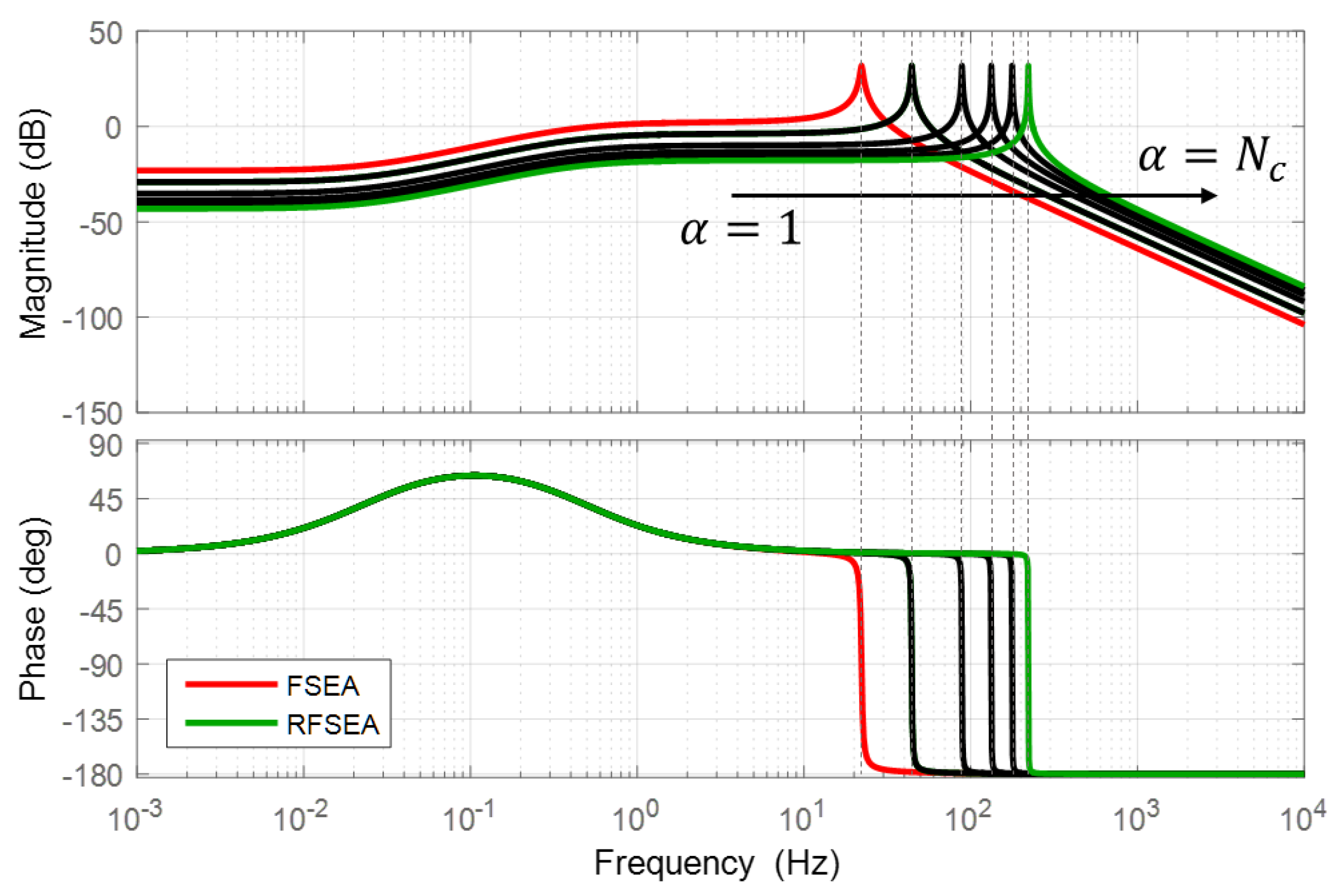
In order to exhibit the influence of the gear ratio distribution on the natural bandwidth of SEA, the open-loop frequency response plot is shown in Figure 22. In this plot, is fixed as 10 and the other parameters are used as Table 6. From the results, it can be seen that the resonance frequency increases as increases. In conclusion, it is shown that the gear ratio distribution changes the natural frequency bandwidth, which will also affects the force control performance.
6. Conclusions
This paper has the following contributions.
- Based on a spring placement, SEA is categorized as Force-sensing Series Elastic Actuator (FSEA), Reaction Force-sensing Series Elastic Actuator (RFSEA) and Transmitted Force-sensing Series Elastic Actuator (TFSEA).
- From the existing SEAs, three different models are chosen with each one falling into one of the above categorizations.
- The dynamics models of the selected SEAs are derived using free-body dynamics and kinematic constraints.
- The frequency response function of each SEA is experimentally measured, and its dynamic model accuracy is verified.
- A generalized dynamic model of SEA which can represent all kinds of SEAs according to the position of the gear ratio and existence of spring system inertia is derived from the generalized framework.
- Three criteria are proposed for comparing performances of SEA using the generalized model of SEA.
- The characteristics of three SEAs are compared based on the proposed criteria.
Acknowledgments
This work was supported by the DGIST Start-up Fund of the Ministry of Science, ICT and Future Planning (2017010057), the National Research Foundation of Korea (NRF) grant funded by the Korea government (MSIP) (NRF-2016R1A2B4016163) and the Global Ph.D. Fellowship Program through the National Research Foundation of Korea (NRF) funded by the Ministry of Education (NRF-2016H1A2A1907509). The authors would like to express our special appreciation to Jinoh Lee in Istituto Italiano di Tecnologia (IIT), Italy. His advices and comments on paper revision as well as on rebuttal process have been invaluable.
Author Contributions
Chan Lee designed and analysed mechanism of SEAs; Suhui Kwak derived the dynamics of SEAs and analyzed the simulation; Jihoo Kwak performed the system identification; those authors equally contributed to writing the paper. Sehoon Oh proposed the criteria and edited the paper.
Conflicts of Interest
The authors declare no conflict of interest.
References
- Vanderborght, B.; Albu-Schäffer, A.; Bicchi, A.; Burdet, E.; Caldwell, D.G.; Carloni, R.; Catalano, M.; Eiberger, O.; Friedl, W.; Ganesh, G.; et al. Variable impedance actuators: A review. Robot. Auton. Syst. 2013, 61, 1601–1614. [Google Scholar] [CrossRef]
- Pratt, G.A.; Williamson, M.M. Series elastic actuators. In Human Robot Interaction and Cooperative Robots, Proceedings of the 1995 IEEE/RSJ International Conference on Intelligent Robots and Systems, Pittsburgh, PA, USA, 5–9 August 1995; IEEE Computer Society Press: Los Alamitos, CA, USA, 1995; Volume 1, pp. 399–406. [Google Scholar]
- Laffranchi, M.; Chen, L.; Kashiri, N.; Lee, J.; Tsagarakis, N.G.; Caldwell, D.G. Development and control of a series elastic actuator equipped with a semi active friction damper for human friendly robots. Robot. Auton. Syst. 2014, 62, 1827–1836. [Google Scholar] [CrossRef]
- Jafari, A.; Tsagarakis, N.G.; Caldwell, D.G. AwAS-II: A new actuator with adjustable stiffness based on the novel principle of adaptable pivot point and variable lever ratio. In Proceedings of the 2011 IEEE International Conference on Robotics and Automation (ICRA), Shanghai, China, 9–13 May 2011; pp. 4638–4643. [Google Scholar]
- Jafari, A.; Tsagarakis, N.G.; Vanderborght, B.; Caldwell, D.G. A novel actuator with adjustable stiffness (AwAS). In Proceedings of the 2010 IEEE/RSJ International Conference on Intelligent Robots and Systems (IROS), Taipei, Taiwan, 18–22 October 2010; pp. 4201–4206. [Google Scholar]
- Sugar, T.G. A novel selective compliant actuator. Mechatronics 2002, 12, 1157–1171. [Google Scholar] [CrossRef]
- Tsagarakis, N.G.; Laffranchi, M.; Vanderborght, B.; Caldwell, D.G. A compact soft actuator unit for small scale human friendly robots. In Proceedings of the IEEE International Conference on Robotics and Automation (ICRA’09), Kobe, Japan, 12–17 May 2009; pp. 4356–4362. [Google Scholar]
- Zhu, J.; Wang, Q.; Wang, L. On the design of a powered transtibial prosthesis with stiffness adaptable ankle and toe joints. IEEE Trans. Ind. Electron. 2014, 61, 4797–4807. [Google Scholar] [CrossRef]
- Yu, H.; Huang, S.; Chen, G.; Pan, Y.; Guo, Z. Human–robot interaction control of rehabilitation robots with series elastic actuators. IEEE Trans. Ind. Electron. 2015, 31, 1089–1100. [Google Scholar] [CrossRef]
- Li, X.; Pan, Y.; Chen, G.; Yu, H. Adaptive Human–Robot Interaction Control for Robots Driven by Series Elastic Actuators. IEEE Trans. Ind. Electron. 2017, 33, 169–182. [Google Scholar] [CrossRef]
- Hutter, M.; Gehring, C.; Höpflinger, M.A.; Blösch, M.; Siegwart, R. Toward Combining Speed, Efficiency, Versatility, and Robustness in an Autonomous Quadruped. IEEE Trans. Robot. 2014, 30, 1427–1440. [Google Scholar] [CrossRef]
- Paine, N.; Mehling, J.S.; Holley, J.; Radford, N.A.; Johnson, G.; Fok, C.L.; Sentis, L. Actuator Control for the NASA-JSC Valkyrie Humanoid Robot: A Decoupled Dynamics Approach for Torque Control of Series Elastic Robots. J. Field Robot. 2015, 32, 378–396. [Google Scholar] [CrossRef]
- Paine, N.; Oh, S.; Sentis, L. Design and control considerations for high-performance series elastic actuators. IEEE/ASME Trans. Mechatron. 2014, 19, 1080–1091. [Google Scholar] [CrossRef]
- Kong, K.; Bae, J.; Tomizuka, M. A compact rotary series elastic actuator for human assistive systems. IEEE/ASME Trans. Mechatron. 2012, 17, 288–297. [Google Scholar] [CrossRef]
- Lee, C.; Oh, S. Configuration and performance analysis of a compact planetary geared Elastic Actuator. In Proceedings of the 42nd Annual Conference of the IEEE on Industrial Electronics Society (IECON 2016), Florence, Italy, 23–26 October 2016; pp. 6391–6396. [Google Scholar]
- Kong, K.; Bae, J.; Tomizuka, M. Torque mode control of a cable-driven actuating system by sensor fusion. J. Dyn. Syst. Meas. Control 2013, 135, 031003. [Google Scholar] [CrossRef]
- Yang, Z.; Sun, Y.; Lei, Y.; Wang, Z.; Zou, W.; Yu, N. Realization and experimental test of a body weight support unit for simultaneous position tracking and gravity offloading. In Proceedings of the 2016 IEEE International Conference on Robotics and Biomimetics (ROBIO), Qingdao, China, 3–7 December 2016; pp. 1064–1068. [Google Scholar]
- Veneman, J.F.; Ekkelenkamp, R.; Kruidhof, R.; van der Helm, F.C.; van der Kooij, H. A series elastic-and bowden-cable-based actuation system for use as torque actuator in exoskeleton-type robots. Intl. J. Robot. Res. 2006, 25, 261–281. [Google Scholar] [CrossRef]
- Lens, T.; von Stryk, O. Design and dynamics model of a lightweight series elastic tendon-driven robot arm. In Proceedings of the 2013 IEEE International Conference on Robotics and Automation (ICRA), Karlsruhe, Germany, 6–10 May 2013; pp. 4512–4518. [Google Scholar]
- Millet, G.; Haliyo, S.; Régnier, S.; Hayward, V. The ultimate haptic device: First step. In Proceedings of the EuroHaptics Conference and Symposium on Haptic Interfaces for Virtual Environment and Teleoperator Systems (World Haptics 2009, Third Joint), Salt Lake City, UT, USA, 18–20 March 2009; pp. 273–278. [Google Scholar]
- Tagliamonte, N.L.; Sergi, F.; Accoto, D.; Carpino, G.; Guglielmelli, E. Double actuation architectures for rendering variable impedance in compliant robots: A review. Mechatronics 2012, 22, 1187–1203. [Google Scholar] [CrossRef]
- Lauria, M.; Legault, M.A.; Lavoie, M.A.; Michaud, F. Differential elastic actuator for robotic interaction tasks. In Proceedings of the IEEE International Conference on Robotics and Automation (ICRA), Pasadena, CA, USA, 19–23 May 2008; pp. 3606–3611. [Google Scholar]
- Oh, S.; Kong, K. High-Precision Robust Force Control of a Series Elastic Actuator. IEEE/ASME Trans. Mechatron. 2017, 22, 71–80. [Google Scholar] [CrossRef]
- Park, Y.; Oh, S.; Zoe, H. Dynamic analysis of Reaction Force sensing Series Elastic Actuator as unlumped two mass system. In Proceedings of the IECON 2016—42nd Annual Conference of the IEEE on Industrial Electronics Society, Florence, Italy, 23–26 October 2016; pp. 5784–5789. [Google Scholar]
- Oh, S.; Lee, C.; Kong, K. Force control and force observer design of series elastic actuator based on its dynamic characteristics. In Proceedings of the IECON 2015—41st Annual Conference of the IEEE on Industrial Electronics Society, Yokohama, Japan, 9–12 November 2015; pp. 004639–004644. [Google Scholar]
- Robinson, D.W.; Pratt, J.E.; Paluska, D.J.; Pratt, G.A. Series elastic actuator development for a biomimetic walking robot. In Proceedings of the 1999 IEEE/ASME International Conference on Advanced Intelligent Mechatronics, Atlanta, GA, USA, 19–23 September 1999; pp. 561–568. [Google Scholar]
- Lee, C.; Choi, W.; Oh, S. Maximum torque generation of SEA under velocity control. In Proceedings of the 2016 IEEE 14th International Workshop on Advanced Motion Control (AMC), Auckland, New Zealand, 22–24 April 2016; pp. 16–23. [Google Scholar]
- Roozing, W.; Malzahn, J.; Kashiri, N.; Caldwell, D.G.; Tsagarakis, N.G. On the Stiffness Selection for Torque-Controlled Series-Elastic Actuators. IEEE Robot. Autom. Lett. 2017, 2, 2255–2262. [Google Scholar] [CrossRef]
- Tsagarakis, N.G.; Caldwell, D.G.; Negrello, F.; Choi, W.; Baccelliere, L.; Loc, V.; Noorden, J.; Muratore, L.; Margan, A.; Cardellino, A.; et al. WALK-MAN: A High-Performance Humanoid Platform for Realistic Environments. J. Field Robot. 2016. [Google Scholar] [CrossRef]
Figure 1.
The SEAs which are categorized in terms of the types of transmission and the types of motion. (a) Series Elastic Actuator [2], (b) University of Texas-Series Elastic Actuator [13], (c) compact Rotary Series Elastic Actuator [14], (d) compact Planetary-geared Elastic Actuator [15], (e) Rotary Series Elastic Actuator [16], (f) Cable Driven Series Elastic Actuator [17], (g) Bowden Cable Driven Series Elastic Actuator [18] and (h) Series elastic actuator of MARIONET [19].
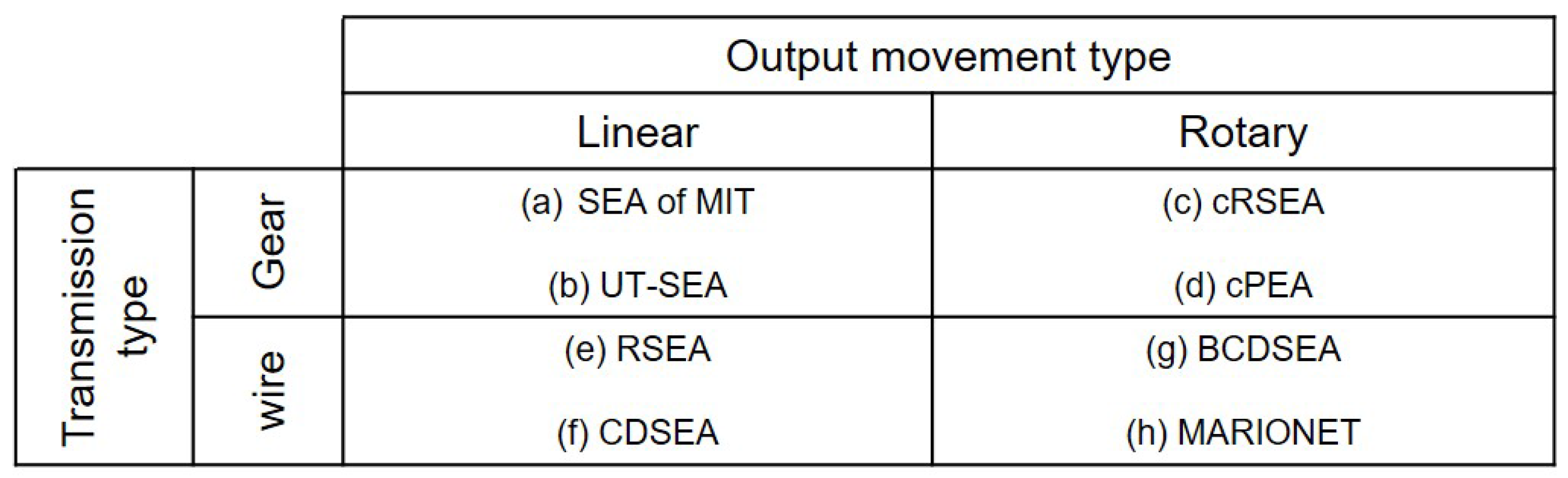
Figure 2.
Overview of organization of this paper.
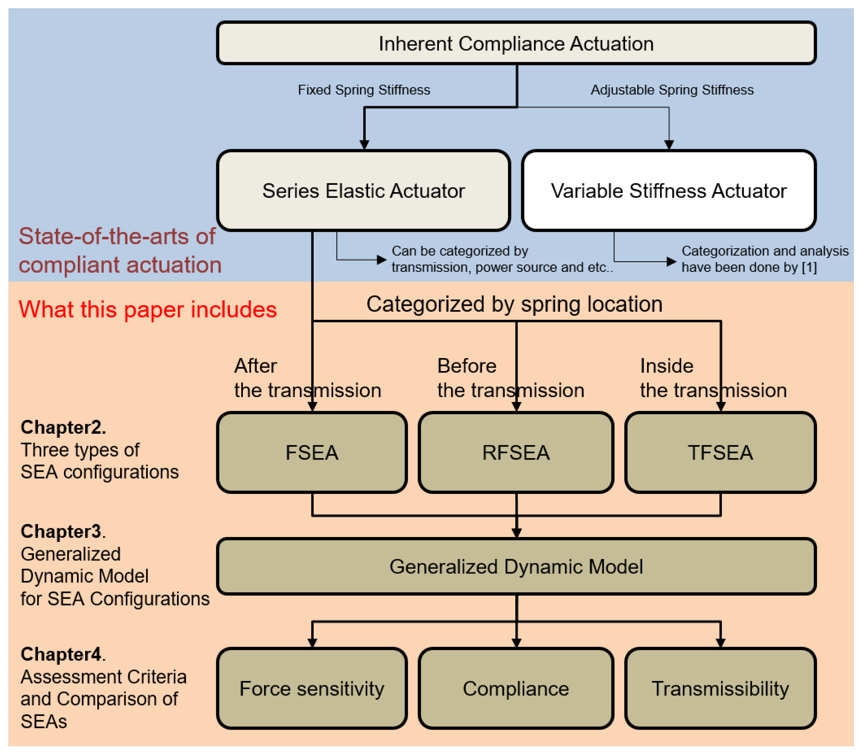
Figure 3.
(a) Rigid Actuator; (b) Series Elastic Actuator.
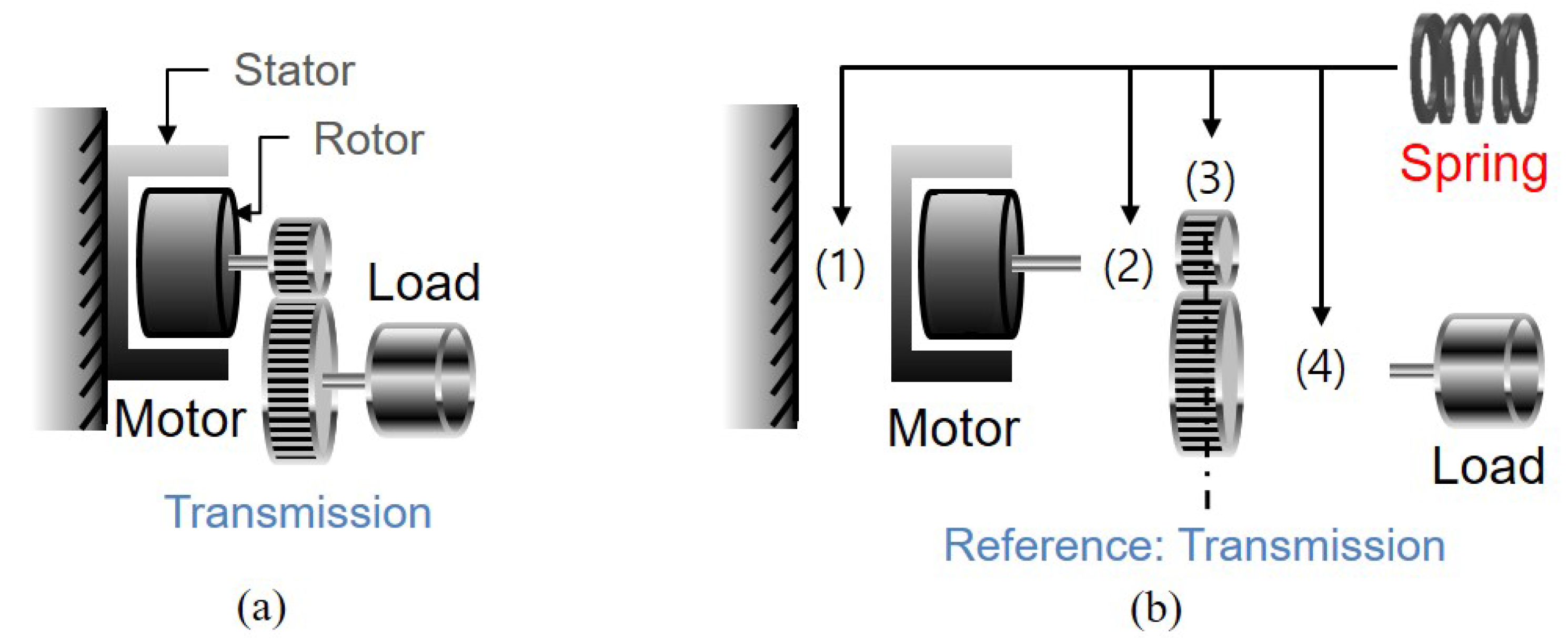
Figure 4.
Configuration of Force-sensing Series Elastic Actuator (FSEA).
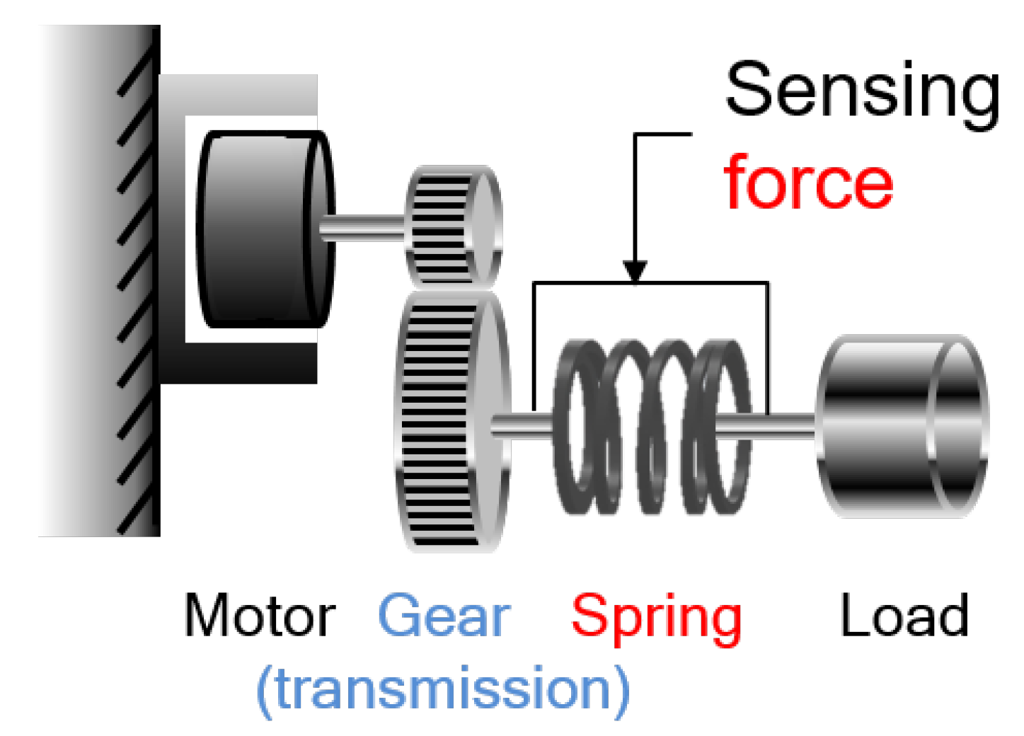
Figure 5.
Example models of FSEA. (a) Series Elastic Actuator (SEA) and (b) compact Rotary Series Elastic Actuator (cRSEA).
Figure 5.
Example models of FSEA. (a) Series Elastic Actuator (SEA) and (b) compact Rotary Series Elastic Actuator (cRSEA).
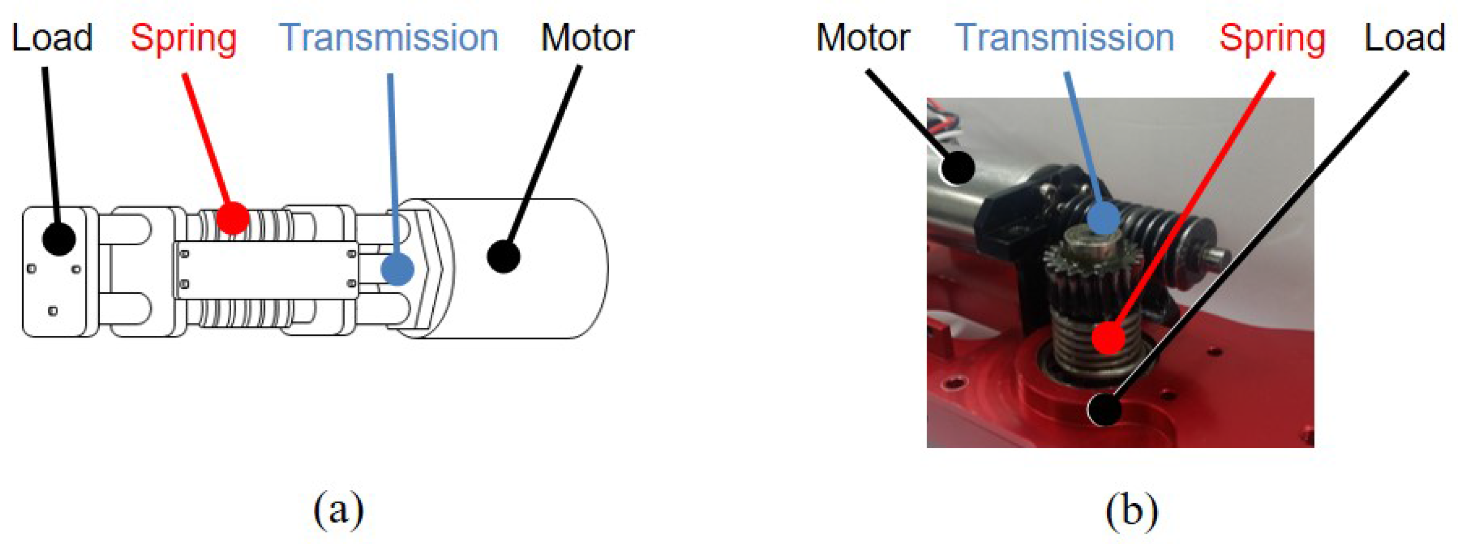
Figure 6.
Configurations of Reaction Force-sensing Series Elastic Actuator (RFSEA). (a) “motor reaction force” sensing type and (b) “gear reaction force” sensing type.
Figure 6.
Configurations of Reaction Force-sensing Series Elastic Actuator (RFSEA). (a) “motor reaction force” sensing type and (b) “gear reaction force” sensing type.

Figure 7.
Example models of RFSEA. (a) University of Texas-Series Elastic Actuator (UT-SEA) and (b) Series Elastic Actuator of MARIONET.
Figure 7.
Example models of RFSEA. (a) University of Texas-Series Elastic Actuator (UT-SEA) and (b) Series Elastic Actuator of MARIONET.

Figure 8.
Configurations of Transmitted Force-sensing Series Elastic Actuator (TFSEA). (a) “internal transmitted force of gear” Sensing type and (b) “external transmitted force of gear” Sensing type.
Figure 8.
Configurations of Transmitted Force-sensing Series Elastic Actuator (TFSEA). (a) “internal transmitted force of gear” Sensing type and (b) “external transmitted force of gear” Sensing type.
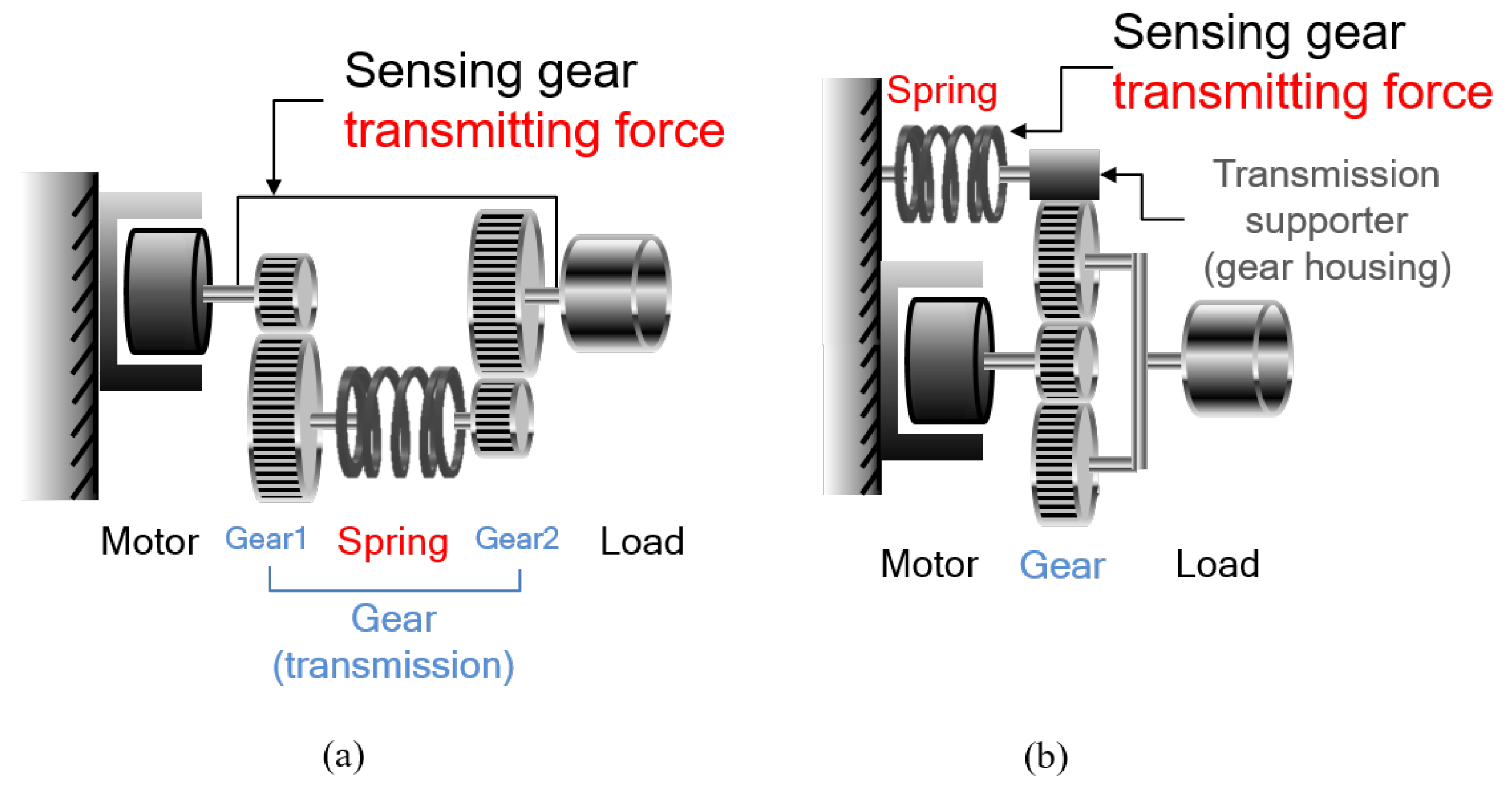
Figure 9.
Example models of TFSEA. (a) Differential Elastic Actuator (DEA) and (b) compact Planetary-geared Elastic Actuator (cPEA).
Figure 9.
Example models of TFSEA. (a) Differential Elastic Actuator (DEA) and (b) compact Planetary-geared Elastic Actuator (cPEA).
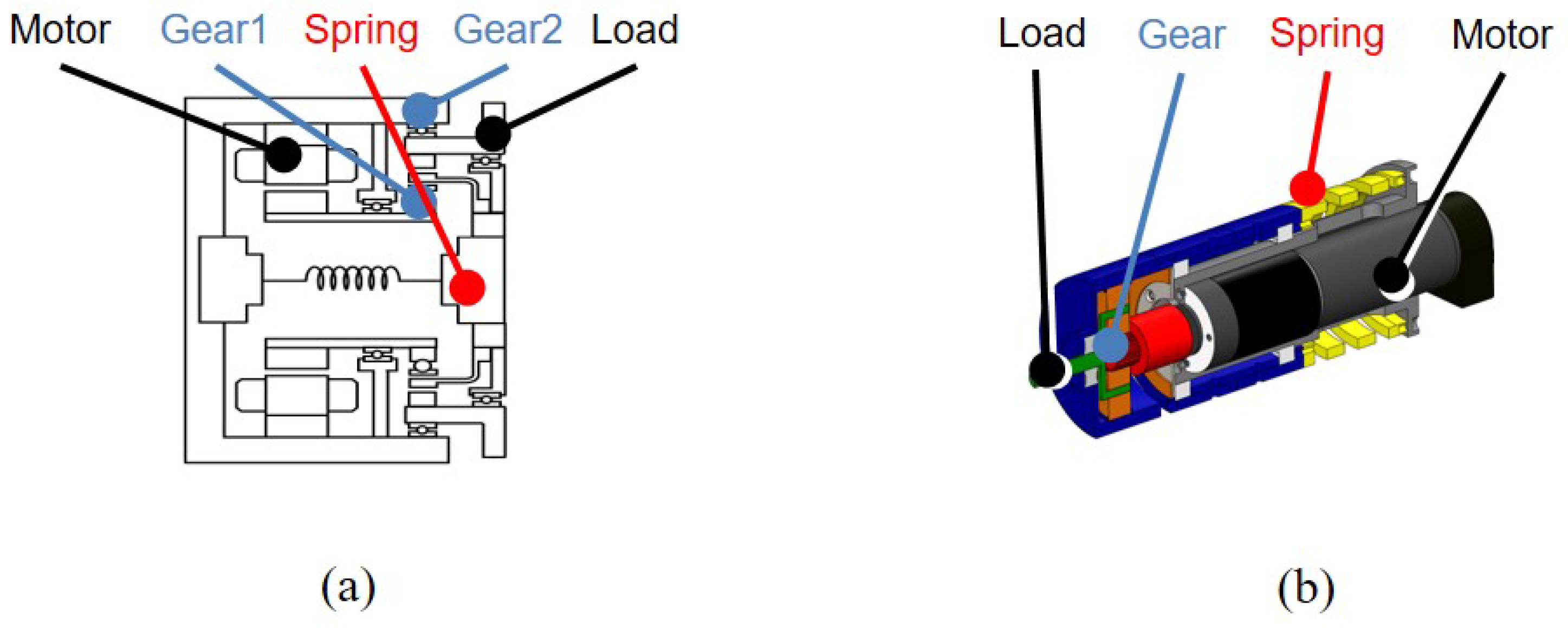
Figure 10.
Dynamic modelling of FSEA. (a) Free-body diagrams of FSEA and (b) block diagram representation of FSEA dynamics.
Figure 10.
Dynamic modelling of FSEA. (a) Free-body diagrams of FSEA and (b) block diagram representation of FSEA dynamics.

Figure 11.
The inertia , and of RFSEA [24].
Figure 11.
The inertia , and of RFSEA [24].
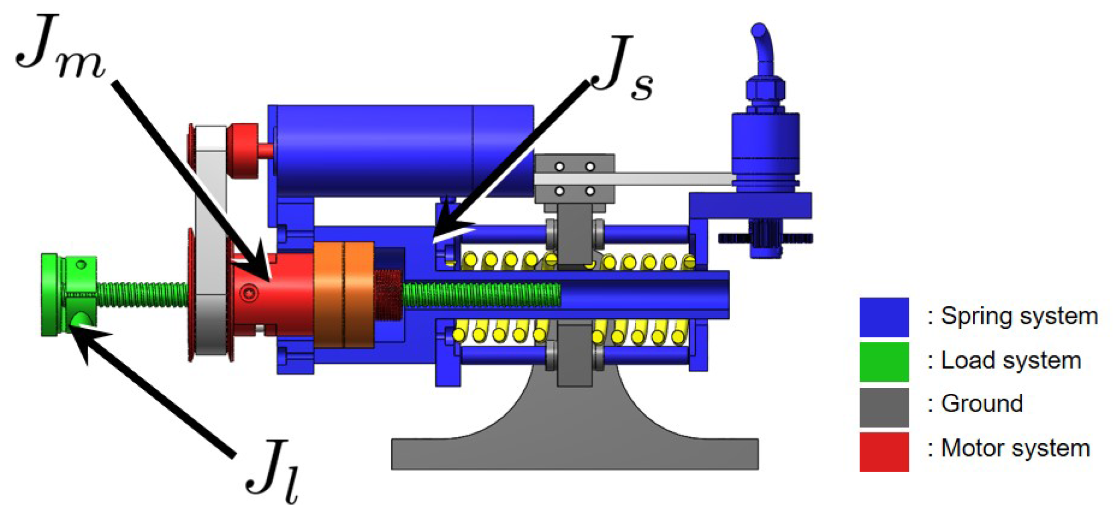
Figure 12.
Dynamic modelling of RFSEA. (a) free-body diagrams of RFSEA and (b) block diagram representation of RFSEA dynamics.
Figure 12.
Dynamic modelling of RFSEA. (a) free-body diagrams of RFSEA and (b) block diagram representation of RFSEA dynamics.

Figure 13.
The inertia , and of cPEA [15].
Figure 13.
The inertia , and of cPEA [15].
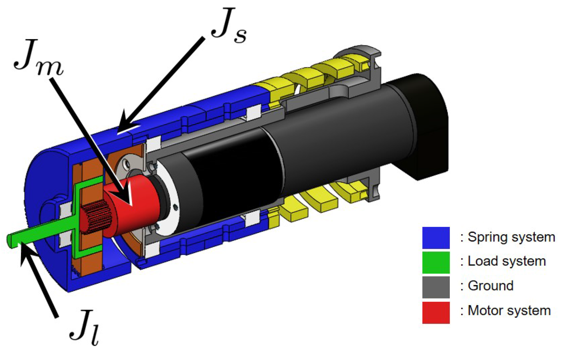
Figure 14.
Dynamic modelling of cPEA. (a) free-body diagrams of cPEA and (b) block diagram representation of cPEA dynamics.
Figure 14.
Dynamic modelling of cPEA. (a) free-body diagrams of cPEA and (b) block diagram representation of cPEA dynamics.

Figure 15.
Frequency Response Functions of cRSEA [25]. (a) FRFs from motor torque to motor velocity and (b) FRFs from motor torque to spring deformation.
Figure 15.
Frequency Response Functions of cRSEA [25]. (a) FRFs from motor torque to motor velocity and (b) FRFs from motor torque to spring deformation.

Figure 16.
Frequency Response Functions of RFSEA [24]. (a) FRFs from motor torque to motor position and (b) FRFs from motor torque to spring deformation.
Figure 16.
Frequency Response Functions of RFSEA [24]. (a) FRFs from motor torque to motor position and (b) FRFs from motor torque to spring deformation.
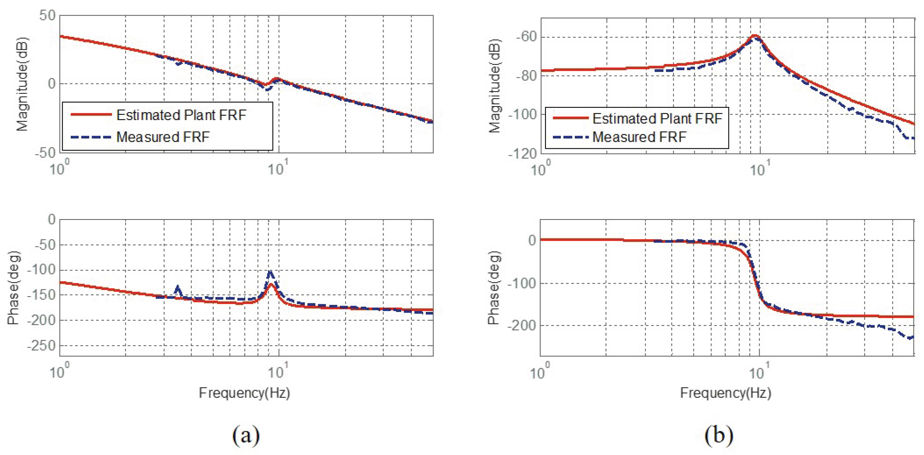
Figure 17.
Frequency Response Functions of cPEA [15]. (a) FRFs from motor torque to motor velocity and (b) FRFs from motor torque to spring deformation.
Figure 17.
Frequency Response Functions of cPEA [15]. (a) FRFs from motor torque to motor velocity and (b) FRFs from motor torque to spring deformation.
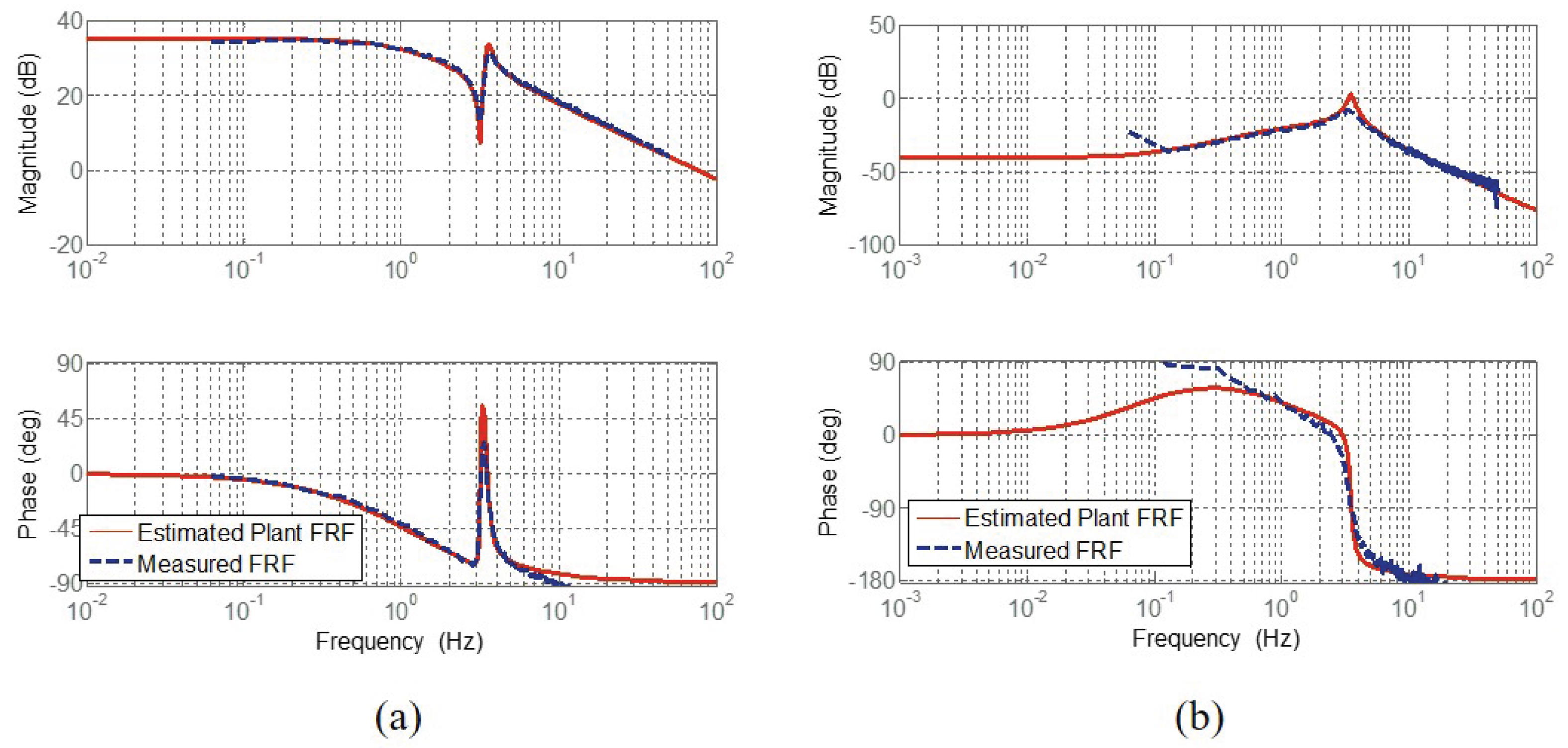
Figure 18.
Block diagram platform of generalized dynamic model of SEA.

Figure 19.
Frequency Response Functions (FRFs) of Force sensitivity.

Figure 20.
Frequency Response Functions (FRFs) of Compliance.

Figure 21.
Frequency Response Functions (FRFs) of Transmissibility.
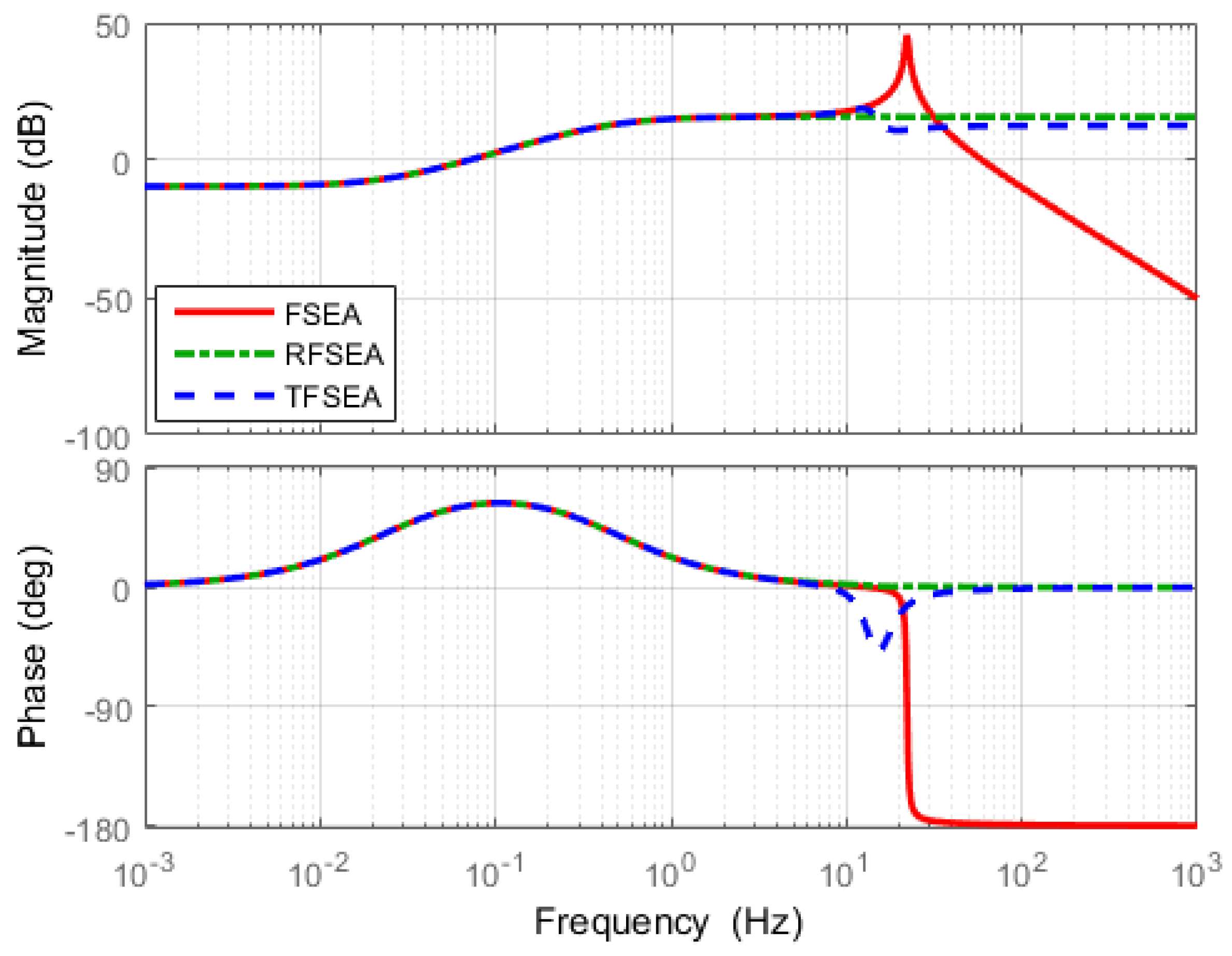
Figure 22.
Frequency responses of open-loop dynamics for SEA force control.

Table 1.
Transfer functions of FSEA.
where .
Table 2.
Transfer functions of RFSEA.
where .
Table 3.
Transfer functions of cPEA.
where .
Table 4.
Generalized parameters of cRSEA, RFSEA and cPEA.
| cRSEA | RFSEA | cPEA | |
|---|---|---|---|
| 1 | N | ||
| 1 | |||
Table 5.
Transfer functions of generalized platform of SEA.
where.
Table 6.
Simulation parameters of SEA criteria.
| Parameter | Value |
|---|---|
| 0.000004 kg | |
| 0.00045 kg | |
| 0.00065 kg | |
| 0.000029 Nm | |
| 0.02 Nm | |
| 0.0001 Nm | |
| 4.8 Nm/rad | |
| N | 10 |
Table 7.
Resonance and anti-resonance frequency of compliance.
| FSEA | RFSEA | TFSEA | |
|---|---|---|---|
Table 8.
Resonance frequency and DC gain of SEA criteria with high gear ratio.
| Force Sensitivity | |||
|---|---|---|---|
| FSEA | RFSEA | TFSEA | |
| 0 | |||
| Compliance | |||
| FSEA | RFSEA | TFSEA | |
| 0 | 0 | ||
| 0 | 0 | 0 | |
| Transmissibility | |||
| FSEA | RFSEA | TFSEA | |
| 0 | 0 | 0 | |
© 2017 by the authors. Licensee MDPI, Basel, Switzerland. This article is an open access article distributed under the terms and conditions of the Creative Commons Attribution (CC BY) license (http://creativecommons.org/licenses/by/4.0/).
Share and Cite
MDPI and ACS Style
Lee, C.; Kwak, S.; Kwak, J.; Oh, S. Generalization of Series Elastic Actuator Configurations and Dynamic Behavior Comparison. Actuators 2017, 6, 26. https://doi.org/10.3390/act6030026
AMA Style
Lee C, Kwak S, Kwak J, Oh S. Generalization of Series Elastic Actuator Configurations and Dynamic Behavior Comparison. Actuators. 2017; 6(3):26. https://doi.org/10.3390/act6030026
Chicago/Turabian StyleLee, Chan, Suhui Kwak, Jihoo Kwak, and Sehoon Oh. 2017. "Generalization of Series Elastic Actuator Configurations and Dynamic Behavior Comparison" Actuators 6, no. 3: 26. https://doi.org/10.3390/act6030026
Note that from the first issue of 2016, this journal uses article numbers instead of page numbers. See further details here.