Stiffness Control of Variable Serial Elastic Actuators: Energy Efficiency through Exploitation of Natural Dynamics


Institute for Mechatronic Systems in Mechanical Engineering, Technische Universität Darmstadt, 64287 Darmstadt, Germany
*
Author to whom correspondence should be addressed.
Actuators 2017, 6(4), 28; https://doi.org/10.3390/act6040028
Submission received: 31 August 2017
/
Revised: 21 September 2017
/
Accepted: 21 September 2017
/
Published: 27 September 2017
(This article belongs to the Special Issue Variable Stiffness and Variable Impedance Actuators)
Abstract
:Variable elastic actuators are very promising for applications in physical human–robot interaction. Besides enabling human safety, such actuators can support energy efficiency, especially if the natural behavior of the system is exploited. In this paper, the power and energy consumption of variable stiffness actuators with serial elasticity is investigated analytically and experimentally. Besides the fundamental mechanics, the influence of friction and electrical losses is discussed. A simple but effective stiffness control method is used to exploit the corresponding knowledge of natural dynamics by tuning the system to antiresonance operation. Despite nonlinear friction effects and additional electrical dynamics, the consideration of the ideal mechanical dynamics is completely sufficient for stiffness control. Simulations and experiments show that this yields a distinct reduction in power and energy consumption, which underlines the suitability of the control strategy.
1. Introduction
Due to increasingly close human–robot interaction, soft or elastic robot designs have received increasing attention [1,2]. Potential applications reach from robotic support for industry workers to assistive and rehabilitation robotics. In both, elastic properties foster human safety [3,4] and can provide motion assistance to their users [5,6]. Regarding the latter, elastic actuators have the potential to distinctly improve energy efficiency. This can be achieved by adapting actuator elasticity to the operating state [7], e.g., by matching the natural frequencies of the system to the trajectory frequency [8,9].
Motivated by these advantages, a variety of actuators with fixed or variable elasticity have been proposed [2]. For safe human-robot interaction, a serial elastic element is placed between drive and link to react to external loads by deformation. While the apparent stiffness of the original SEA is modified by control [10], various solutions to physically alter joint elasticity exist [2] and are categorized according to their fundamental working principles [11], namely, equilibrium-controlled, structure-controlled, mechanically controlled, and antagonistic-controlled stiffness. The latter three feature a physical variable stiffness implemented by mechanisms to modify the structure of the elastic element, its pretension or preload, or coupling two SEAs antagonistically, respectively.
Together with the mechanisms, several control methods for stiffness adjustment have been proposed. Besides reducing power consumption [12,13], approaches aim at setting end effector stiffness [14], ensuring user-safety [15], and improving dynamic behavior [16,17]. A simple but efficient class of stiffness controllers rely on PID-type feedback [17,18]. Beyond these, more complex nonlinear feedback techniques, such as sliding mode control [19] and feedback linearization [20], exist. Yet, for improved energy efficiency, the combination of PID-type feedback with system dynamics models appears promising since it facilitates the exploitation of antiresonance operation [8,13,21].
This paper presents analytical and experimental investigations of the model-extended PID control approach suggested in [21,22] on a variable stiffness actuator. To this end, actuator models including friction and the DC motor are set up to calculate the natural and antiresonance frequencies in Section 2. Section 3 analyzes the energy consumption of the system in comparison to its natural behavior. The applied models and analysis methods rely on [8] and are used to comprehend the behavior of the investigated system. The main contribution of the paper is the extended analysis of the stiffness control strategy that was proposed in [21]. The approach is described and examined in simulations in Section 4. Experimental results are presented and evaluated in Section 5. Finally, Section 6 concludes the paper by discussing the main findings.
2. Actuator Modeling
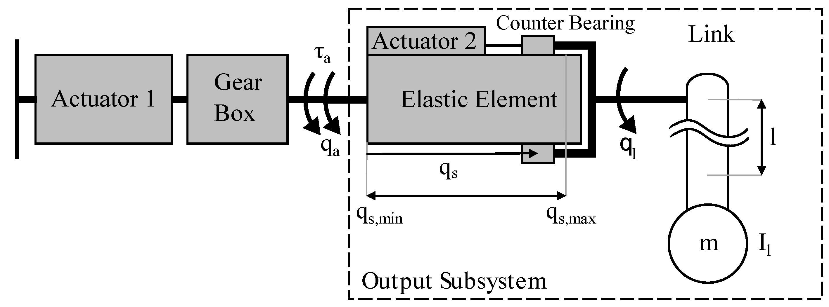
A pendulum driven by a serial elastic actuator is analyzed to explore how natural dynamics influence energy efficiency (see Figure 1). Due to the similar setup, the results are directly comparable to those from [8]. The impact of varying serial stiffness is analyzed based on natural dynamics and inverse dynamics simulations. In addition to inertial and gravitational effects, mechanical and electrical losses are included in the models as suggested in [8].
2.1. Dynamics Equations
A sketch of the considered pendulum, which is driven by a serial elastic actuator with variable torsion stiffness, is given in Figure 1. Actuator 1 and the corresponding gear box are connected to the pendulum link by a serial elastic element with the torsional stiffness . The actuator and link positions, and , are induced by the torque that is generated by Actuator 1. The rotational inertial parameters of actuator and link are denoted by and , while represents the mass of the pendulum. Stiffness adjustment is performed by Actuator 2 that relocates a counter bearing and thereby changes the effective length and hence the stiffness of the elastic element [13].
A general description of elastic joint dynamics considering multi-joint robotic systems is derived with the Lagrange formalism in [23]. In the single-link case of the pendulum example, the positions and as well as the torque represent scalars. Combining both positions into a vector , the dynamics are given by
In this, no Coriolis and centrifugal effects appear, and is a constant due to the single-link setup. Gravitational effects are modeled by .
2.2. Natural Dynamics
To investigate the impact of natural dynamics on energy efficiency, the linearized dynamics of the pendulum are considered. According to the analyses in [8,22], the system exhibits two natural frequencies and an antiresonance frequency . When the actuator operates at the natural frequencies, a very low torque is required [22]. Contrary, the required motions of the actuator are very small if the system operates at antiresonance frequency
3. Energy Consumption Analysis
Aimed at optimizing energy efficiency, mechanical and electrical power requirements are determined by an inverse dynamics calculation with the presented models. To examine how those requirements are influenced by natural dynamics and stiffness variation, the results are juxtaposed to the analytically obtained natural and antiresonance frequencies. Moreover, mechanical losses due to friction at actuator and link [24] are considered. Experiments show that the link losses are mainly comprised of Coulomb friction of the bearing, which can be described by
In this, represents the amplitude and determines the direction of the resulting torque. In [24], Coulomb, Stribeck, and viscous friction are experimentally observed at the actuator and modeled by
Coulomb and viscous friction are represented using the coefficient and , respectively. The amplitude, form factor, and velocity of the Stribeck friction are characterized by , , and , respectively.
3.1. Energy Calculation
The actuator motion and torque corresponding to a desired motion of the link are determined by inverse dynamics to calculate power consumption. Therefore, actuator motion is determined via the upper line of the dynamic equations given by Equation (1) and link-side friction for the desired motion by Equation (3), which yields
where and its derivatives represent the desired motion of the pendulum. With Equation (5) and the lower line of Equation (1) while considering motor-side friction for the desired motion determined from Equation (4), the required actuator torque is calculated by
To obtain the required actuator power, actuator torque is multiplied with actuator velocity, i.e., the derivative of Equation (5). The corresponding energy consumption is evaluated by integration over time:
As the desired pendulum position , sinusoidal link motions of the link with the amplitude and the frequency are investigated.
3.2. Electrical Model Extensions
Losses occurring in the electrical motor can be described by a motor model [8]. Assuming a linear relationship between the motor current I and the desired actuator torque via the torque constant , yields
It needs to be considered that the motor torque is increased by the gearbox with a transmission ratio . In contrast to [8], motor damping is included in the friction model Equation (4). Hence, the motor voltage U is given by
Thereby, R is the winding resistance, L the terminal inductance, and the speed constant of the motor. This differential equation is simplified by neglecting the terminal inductance, which does not have a high impact on the quality of the model for sinusoidal trajectories as discussed in [8]. Hence, by utilizing Equations (8) and (9), the electrical energy is gained by integrating the electrical power over time according to
3.3. Results
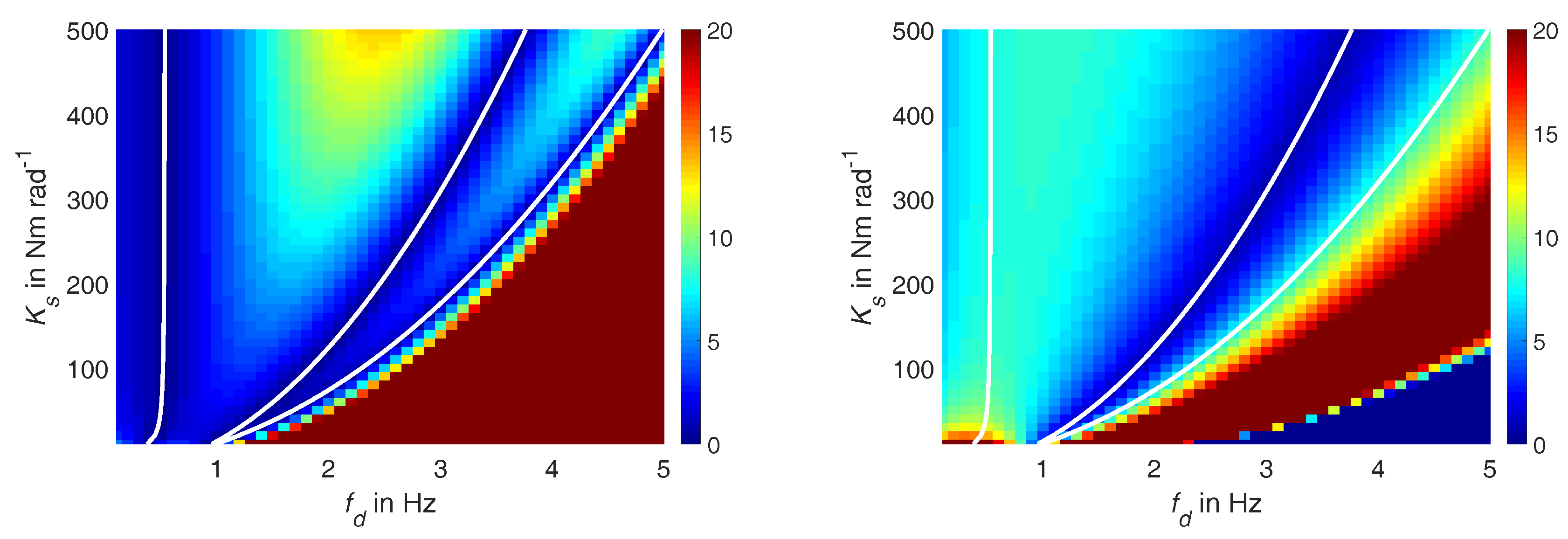
To get insight into energy consumption, inverse dynamics calculations of the energy consumed during tracking a sinusoidal trajectory, with varying frequencies and a fixed amplitude of , are analyzed. To this end, power is integrated over the period to determine the consumed energy per oscillation. The considered parameters of the variable torsion stiffness (VTS) prototype are determined in [13,22,24] and summarized in Table 1. The serial stiffness is varied.
The left plot in Figure 2 presents the mechanical energy consumption of the ideal system depending on the series stiffness and the oscillation frequency . For comparison to the system dynamics, the linearized natural (left and right line) and antiresonance (middle line) frequencies are highlighted in white. Distinct minima of required energy are observed in the areas of the first and second natural frequencies as well as the antiresonance. As mentioned above, this is due to the low required torque when operating at natural frequencies and small required motions at antiresonance. This confirms the results of [8] regarding the VTS-actuator.
The behavior of the system when considering friction is given in the right part of Figure 2. In this case, Coulomb friction at link and actuator leads to higher required torques at the natural frequencies. In contrast, the minimum in actuator velocity also minimizes the actuator friction according to the model presented in Equation (4). Hence, a clear minimum exists only around the antiresonance of the system (middle white line).
Considering electrical losses of the actuator in addition to the ideal system dynamics leads to the results presented left in Figure 3. Due to the characteristic behavior of the DC motor, the respective efficiency is very low at slow velocities and the minimum in mechanical energy at the antiresonance is mostly compensated by high actuator losses. Thus, operation at the first and second natural frequency appears advantageous to minimize electrical losses of the system.
If mechanical and electrical losses are considered simultaneously, the calculation yields the total required energy shown in the right part of Figure 3. As can be seen, for frequencies up to approximately 2.5 , antiresonance provides the lowest energy consumption. For higher frequencies, the minimum approaches the area of the second natural mode. Both is in accordance with the results presented in [8], although the parameters of the considered systems differ. Hence, the optimal stiffness value for a particular oscillation frequency below 2.5 can be selected by determining the antiresonance of the linearized system.
4. Stiffness Control
As shown above, the consumed energy of the system can be minimized by antiresonance operation. In variable elastic actuators, this can be used to control the actuator stiffness. Considering the structure-controlled stiffness of the VTS-actuator , the active length of the elastic element is adjusted by moving the counter bearing depicted in Figure 1 with Actuator 2. The elastic element is implemented as a torsional rod [26,27] and its stiffness characteristics are represented by
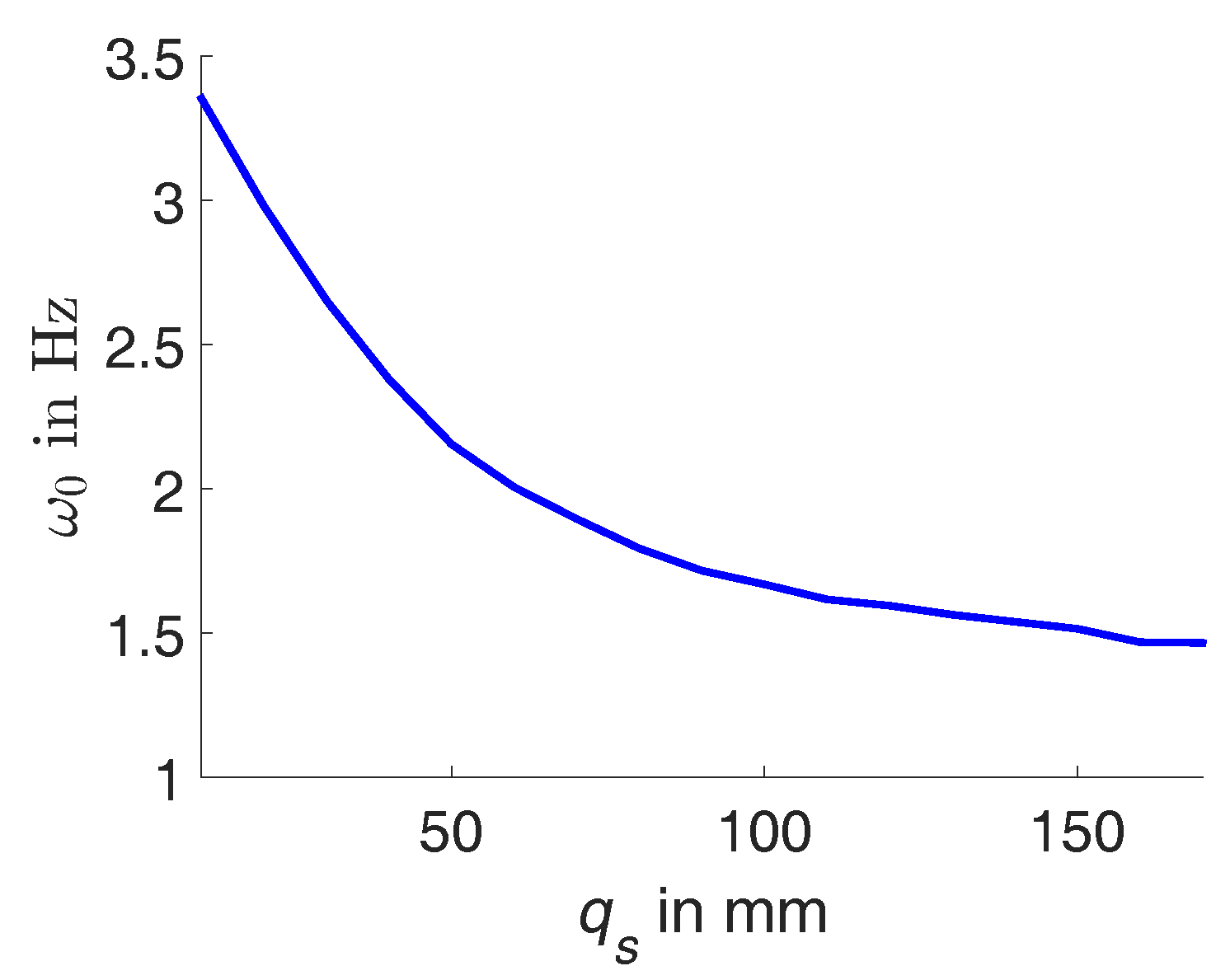
where G is the shear modulus of the material and the torsional moment of inertia of the elastic element with a quadratic cross section. This correlation between the stiffness and the active length can be used to reformulate the antiresonance in Equation (2) as a function of the position of the counter bearing . The resulting mapping between active length and antiresonance frequency is shown in Figure 4. To obtain this characteristic curve, free oscillation experiments of the link are performed with the actuator being locked [24]. The natural frequency of the remaining single mass oscillator coincide with the antiresonance of the whole VTS system.
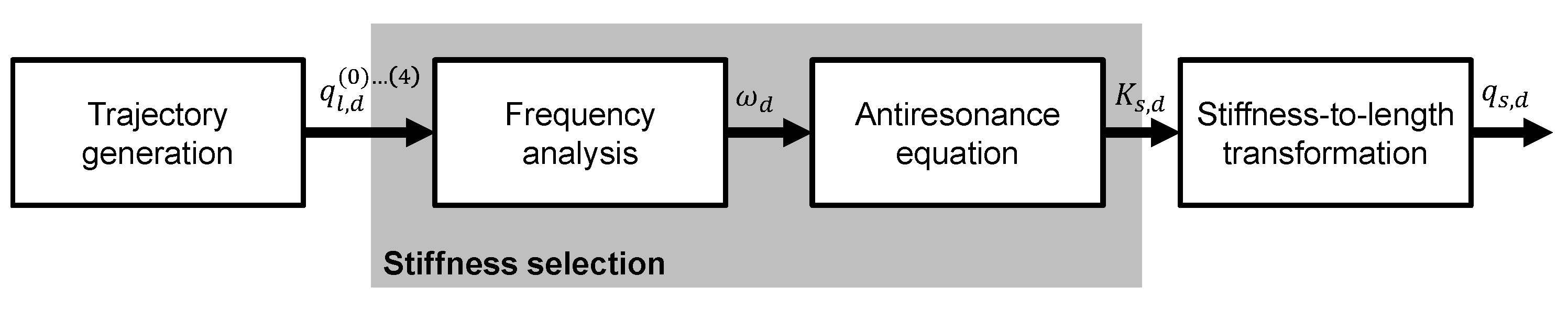
Knowing the mapping between active length and antiresonance enables the control of stiffness by setting the corresponding positions of the counter bearing. Figure 5 shows a block diagram of the stiffness selection suggested in [21,22]. Frequency analysis of the link trajectory yields a time-dependent approximation of the dominant motion frequency . Accordingly, stiffness , which needs to be positive to maintain stability, is selected from the antiresonance equation Equation (2). This value is transformed to a desired active length or counter bearing position , which can be set by common position controllers.
To outline the function of the stiffness adjustment approach, Figure 6 shows simulation results including friction losses. A sine trajectory with an amplitude of 5 and a known frequency of 1.6 is tracked and, initially, the length of the system is set to a value deviating from antiresonance. At 13.6 , the active length is adjusted to bring the system to antiresonance operation on a predefined trajectory. The effect of the antiresonance operation is presented in the right part of Figure 6. As expected, a residual actuator motion is required to compensate for the losses at the link. Yet, the amplitude of the required mechanical actuator power is distinctly reduced from approximately 2 to 0.5 . Alongside, the consumed energy per oscillation declines from 0.47 to 0.08 after the adjustment.
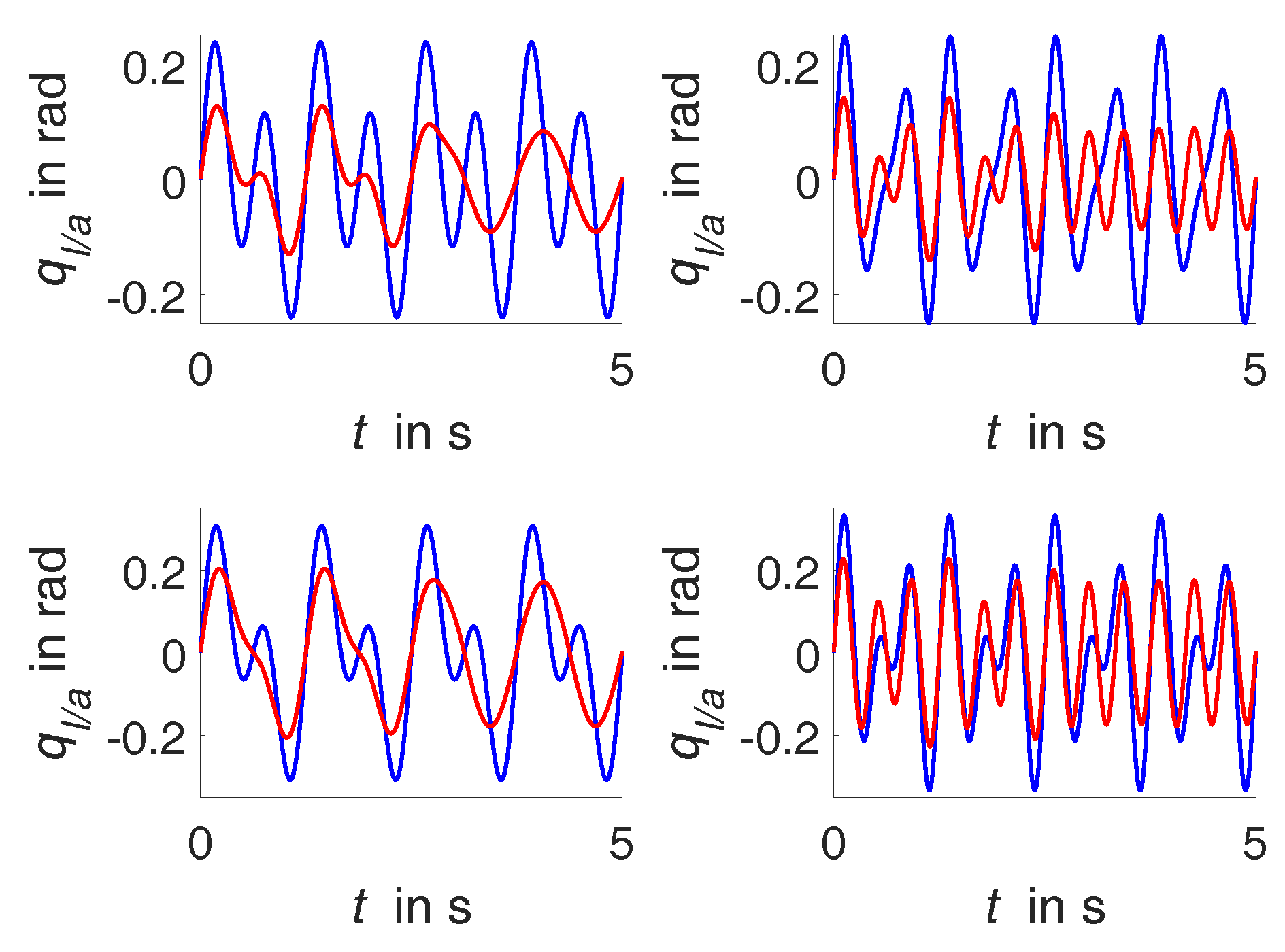
To emphasize that the motion frequency that resembles antiresonance is removed from motor motion, simulations with different dual sinusoidal trajectories are performed. Thereby, a base trajectory with 1.6 is superimposed with a second sinusoidal motion with 0.8 and 2.4 , respectively. Setting the antiresonance to 1.6 throughout the simulation results in a, nearly, sinusoidal motor motion of 0.8 or 2.4 , respectively, as shown in Figure 7. While the effect is independent from the actual amplitude of components in the signal, the adjustment of antiresonance should focus on the frequency with the highest energy to achieve maximum reduction in energy consumption.
5. Experimental Evaluation
Subsequently, the experimental evaluation of the correlation between power consumption and natural dynamics and its exploitation by control is presented.
5.1. Experimental Setup
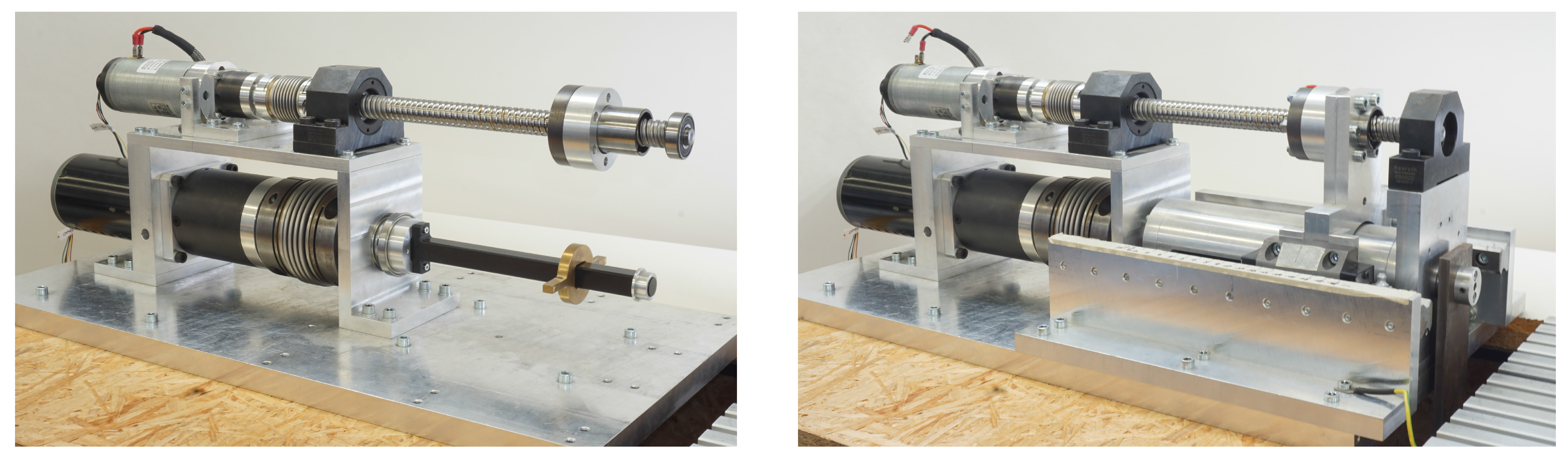
The experimental evaluation is performed using the VTS actuator introduced in [13] and presented in Figure 8. The actuator-gearbox unit in the lower left of the system drives a pendulum load located on the right. The series elasticity is realized by a polyoxymethylene rod (black). The torque of the lower actuator is transferred to the pendulum through a relocatable brass slider and a slitted tube [13,22]. The position of the slider is set via the upper actuator and a ball screw mechanism. Both actuators and the link are equipped with optical motion encoders and motor drivers with low-level current control.
For appropriate tracking of the desired link trajectories and comparability between simulation and experiments, the pendulum motions are controlled using feedback linearization and a feed-forward friction compensator [25]. Stiffness control is performed using the previously presented approach by setting the position of the counter bearing according to the major frequency of the desired link motion. While [21,22] suggested spectral analysis methods to determine the frequency from the trajectory, the LabVIEW Extract Single Tone Information VI from National Instruments, Austin, TX, USA, is used. Based on the characteristics presented in Figure 4, the position of the counter bearing for antiresonance operation is determined and used as the set value of a PID position controller.
5.2. Sinusoidal Trajectory Experiments
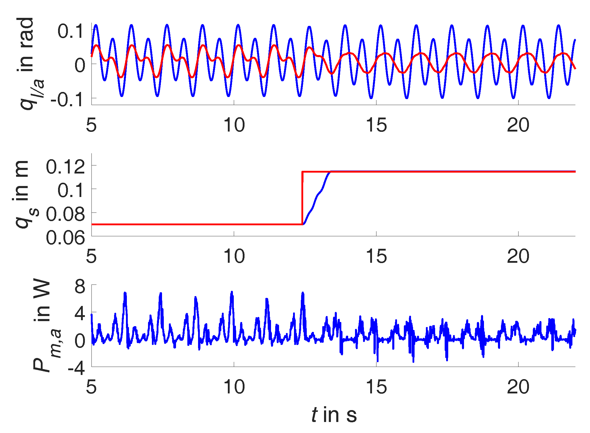
The upper plot of Figure 9 shows the actual positions of link and actuator for a sinusoidal trajectory with 1.6 , which both show appropriate tracking results. Initially, actuator stiffness is set to deviate from the value that yields antiresonance behavior. The middle plot shows how the PID position controller sets stiffness to the determined value within one link oscillation. Accordingly, the power consumption of the actuator that drives the link is distinctly reduced during this adjustment process. Since those observations are matching the simulation results very well, the feasibility of the stiffness control approach is confirmed. The adjustment within a single oscillation underlines the online capability of the approach. Through the continuous analysis of the desired trajectories, the strategy can be applied to arbitrary and unknown trajectories. This is substantiated by superimposing a sinusoidal trajectory with 1.6 with a second sinusoidal trajectory with 0.8 at a halved amplitude, yielding a dual sine trajectory as depicted in Figure 10. To maximize the effect, the controller is set to match the natural behavior to the frequency with the highest power in the signal, which is detected by frequency analysis. Thus, the stiffness value corresponding to 1.6 is selected, which equals the stiffness from the sinusoidal motion presented in Figure 9. Remarkably, the motor only performs a sinusoidal motion with 0.8 to achieve a dual sine at the link, which is accompanied with reduced power consumption.
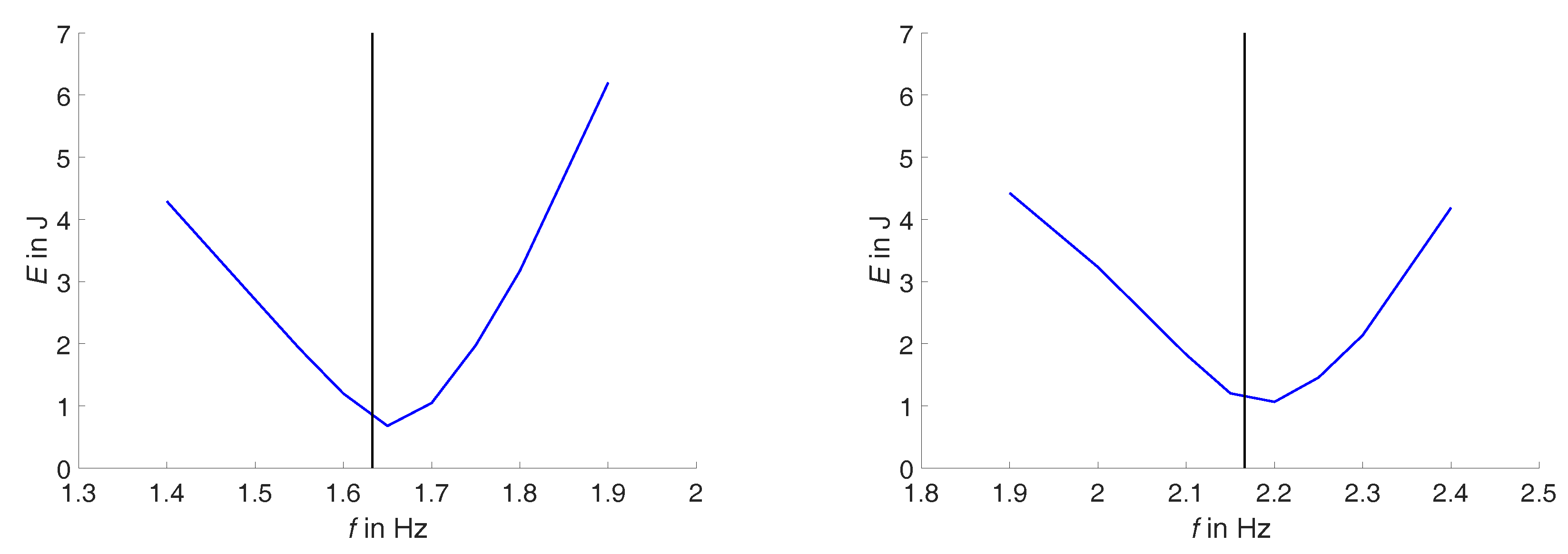
To investigate the energy consumption of the system over a broader range of frequencies, the energy-frequency behavior for fixed stiffness is experimentally determined and presented in Figure 11. The experimentally obtained characteristics (blue) exhibit the energy minimum close to the calculated antiresonance frequency. This substantiates that Equation (2) is well-suited to determine stiffness values for energy efficient operation.
6. Discussion and Conclusions
This paper extends the analysis of the stiffness control strategy for variable stiffness actuators that was proposed in [21]. To implement and analyze the strategy on a variable torsion stiffness (VTS) actuator, the natural dynamics and energy consumption of the system are analyzed and related to each other as suggested in [8]. The analytical and experimental analyses show that the antiresonance operation is very suitable, which confirms the results from [8,9] on a system with different dynamical parameters, i.e., the VTS-actuator [13,26]. As in the previous studies, the influence of friction and electrical losses is investigated and has distinct impacts on power and energy consumption. Due to these impacts, only antiresonance operation fosters energy efficiency while the natural frequencies lead to no improvement.
The stiffness control method suggested in [21,22] is applied to exploit natural dynamics by tuning the system to antiresonance operation. Simulations and experiments highlight the suitability and, especially, the online capabilities of the approach. Without prior knowledge of the desired trajectory, the stiffness is adjusted to bring the system to a more energy-efficient operating point with very low delay. If different frequencies are superimposed, tuning to the natural frequency can be used to compensate for the power consumption that is caused by the dominating motion frequency. Hence, the motor has only to provide the energy, which is necessary for the other frequency components of the trajectory and to compensate for losses. In accordance with [8], it is observed that the analytical expression Equation (2) gives a good estimation of the required stiffness without considering nonlinear friction or the dynamics of the electrical subsystem. This simplifies the implementation of the stiffness control strategy for systems with similar dynamics. Yet, systems with multiple degrees of freedom and complex kinematics might require advanced models. Nevertheless, the control approach leads to distinct reductions of power and energy consumption, which is presented in simulations and experiments. Another advantage of the proposed stiffness control strategy is its independence from the link controller. While link motion is controlled by feedback linearization in this paper, the results from [22] show that it is also applicable in combination with impedance and force control.
After this study highlights the suitability of the proposed stiffness control strategy, future investigations might consider other trajectories and systems with different natural dynamics. Moreover, the examination of potential influences due to human–robot interaction appears promising.
Acknowledgments
This work was supported by Deutsche Forschungsgemeinschaft (DFG) (No. BE 5729/1 and No. BE 5729/2). The authors received no funds for covering the costs to publish in open access.
Author Contributions
P.B. and F.S. conceived and designed the experiments; F.S. performed the experiments; P.B. and F.S. analyzed the data; S.R. contributed materials and analysis tools; P.B. and F.S. wrote the paper; all authors revised the content.
Conflicts of Interest
The authors declare no conflict of interest. The funding sponsors had no role in the design of the study; in the collection, analyses, or interpretation of data; in the writing of the manuscript, and in the decision to publish the results.
References
- Albu-Schäffer, A.; Eiberger, O.; Grebenstein, M.; Haddadin, S.; Ott, C.; Wimbock, T.; Wolf, S.; Hirzinger, G. Soft Robotics. IEEE Robot. Autom. Mag. 2008, 15, 20–30. [Google Scholar] [CrossRef]
- Vanderborght, B.; Albu-Schaeffer, A.; Bicchi, A.; Burdet, E.; Caldwell, D.G.; Carloni, R.; Catalano, M.; Eiberger, O.; Friedl, W.; Ganesh, G.; et al. Variable Impedance Actuators: A review. Robot. Auton. Syst. 2013, 61, 1601–1614. [Google Scholar] [CrossRef]
- Haddadin, S.; Albu-Schaeffer, A.; De Luca, A.; Hirzinger, G. Collision Detection and Reaction: A Contribution to Safe Physical Human–Robot Interaction. In Proceedings of the IEEE International Conference on Robotics and Automation, Nice, France, 22–26 September 2008. [Google Scholar]
- Lens, T.; von Stryk, O. Investigation of Safety in Human–Robot-Interaction for a Series Elastic, Tendon-Driven Robot Driven Robot Arm. In Proceedings of the IEEE/RSJ International Conference on Intelligent Robots and Systems, Vilamoura, Portugal, 7–12 October 2012. [Google Scholar]
- Windrich, M.; Grimmer, M.; Christ, O.; Rinderknecht, S.; Beckerle, P. Active Lower Limb Prosthetics: A Systematic Review of Design Issues and Solutions. BioMed. Eng. OnLine 2016, 15, 5–19. [Google Scholar] [CrossRef] [PubMed]
- Veneman, J.; Burdet, E.; van der Kooij, H.; Lefeber, D. Emerging Directions in Lower Limb Externally Wearable Robots For Gait Rehabilitation and Augmentation—A Review. In Advances in Cooperative Robotics; World Scientific Publishing Co. Pte. Ltd.: Singapore, 2017; pp. 840–850. [Google Scholar]
- Vanderborght, B.; Van Ham, R.; Lefeber, D.; Sugar, T.G.; Hollander, K.W. Comparison of Mechanical Design and Energy Consumption of Adaptable, Passive-Compliant Actuators. Int. J. Robot. Res. 2009, 28, 90–103. [Google Scholar] [CrossRef]
- Verstraten, T.; Beckerle, P.; Furnémont, R.; Mathijssen, G.; Vanderborght, B.; Lefeber, D. Series and Parallel Elastic Actuation: Impact of Natural Dynamics on Power and Energy Consumption. Mech. Mach. Theory 2016, 102, 232–246. [Google Scholar] [CrossRef]
- Beckerle, P.; Verstraten, T.; Mathijssen, G.; Furnémont, R.; Vanderborght, B.; Lefeber, D. Series and Parallel Elastic Actuation: Influence of Operating Positions on Design and Control. IEEE/ASME Trans. Mechatron. 2017, 22, 521–529. [Google Scholar] [CrossRef]
- Pratt, G.A.; Williamson, M.M. Series Elastic Actuators. In Proceedings of the IEEE/RSJ International Conference on Intelligent Robots and Systems, Pittsburgh, PA, USA, 5–9 August 1995. [Google Scholar]
- Van Ham, R.; Sugar, T.G.; Vanderborght, B.; Hollander, K.W.; Lefeber, D. Compliant Actuator Designs Review of Actuators with Passive Adjustable Compliance/Controllable Stiffness for Robotic Applications. IEEE Robot. Autom. Mag. 2009, 16, 81–94. [Google Scholar]
- Vanderborght, B.; Verrelst, B.; Van Ham, R.; Van Damme, M.; Beyl, P.; Lefeber, D. Development of a Compliance Controller to Reduce Energy Consumption for Bipedal Robots. Auton. Robot. 2008, 24, 419–434. [Google Scholar] [CrossRef]
- Beckerle, P.; Wojtusch, J.; Schuy, J.; Strah, B.; Rinderknecht, S.; Stryk, O.V. Power-Optimized Stiffness and Nonlinear Position Control of an Actuator with Variable Torsion Stiffness. In Proceedings of the IEEE/ASME International Conference on Advanced Intelligent Mechatronics, Wollongong, NSW, Australia, 9–12 July 2013. [Google Scholar]
- Palli, G.; Melchiorri, C. On the Control of Redundant Robots with Variable Stiffness Actuation. In Proceedings of the IEEE/RSJ International Conference on Intelligent Robots and Systems, Vilamoura, Portugal, 7–12 October 2012. [Google Scholar]
- Tonietti, G.; Schiavi, R.; Bicchi, A. Design and Control of a Variable Stiffness Actuator for Safe and Fast Physical Human/Robot Interaction. In Proceedings of the IEEE International Conference on Robotics and Automation, Barcelona, Spain, 18–22 April 2005. [Google Scholar]
- Huh, S.; Tonietti, G.; Bicchi, A. Neural Network Based Robust Adaptive Control for a Variable Stiffness Actuator. In Proceedings of the Mediterranean Conference on Control and Automation, Ajaccio, France, 25–27 June 2008. [Google Scholar]
- Albu-Schäffer, A.; Wolf, S.; Eiberger, O.; Haddadin, S.; Petit, F.; Chalon, M. Dynamic Modelling and Control of Variable Stiffness Actuators. In Proceedings of the IEEE International Conference on Robotics and Automation, Anchorage, AK, USA, 3–8 May 2010. [Google Scholar]
- Sardellitti, I.; Medrano-Cerda, G.A.; Tsagarakis, N.; Jafari, A.; Caldwell, D.G. Gain Scheduling Control for a Class of Variable Stiffness Actuators Based on Lever Mechanisms. IEEE Trans. Robot. 2013, 29, 791–798. [Google Scholar] [CrossRef]
- Huh, S.H.; Bien, Z. Robust Sliding Mode Control of a Robot Manipulator based on Variable Structure-Model Reference Adaptive Control Approach. IET Control Theory Appl. 2007, 1, 1355–1363. [Google Scholar] [CrossRef]
- De Luca, A.; Flacco, F.; Bicchi, A.; Schiavi, R. Nonlinear Decoupled Motion-Stiffness Control and Collision Detection/Reaction for the VSA-II Variable Stiffness Device. In Proceedings of the IEEE/RSJ International Conference on Intelligent Robots and Systems, St. Louis, MO, USA, 10–15 October 2009. [Google Scholar]
- Beckerle, P.; Rinderknecht, S. A Variable Stiffness Control Strategy Using System Dynamics and Spectral Trajectory Analysis. In Proceedings of the International Workshop on Human–Machine Systems, Cyborgs and Enhancing Devices, Manchester, UK, 13 October 2013. [Google Scholar]
- Beckerle, P. Human–Machine-Centered Design and Actuation of Lower Limb Prosthetic Systems; Shaker Verlag: Herzogenrath, Germany, 2014. [Google Scholar]
- Albu-Schäffer, A. Regelung von Robotern mit Elastischen Gelenken am Beispiel der DLR-Leichtbauarme. Ph.D. Thesis, Technische Universität München, München, Germany, 2002. [Google Scholar]
- Lendermann, M.; Stuhlenmiller, F.; Erler, P.; Beckerle, P.; Rinderknecht, S. A Systematic Approach to Experimental Modeling of Elastic Actuators by Component-Wise Parameter Identification. In Proceedings of the 2015 IEEE/RSJ International Conference on Intelligent Robots and Systems, Hamburg, Germany, 28 September–2 October 2015. [Google Scholar]
- Erler, P.; Beckerle, P.; Strah, B.; Rinderknecht, S. Experimental Comparison of Nonlinear Motion Control Methods for a Variable Stiffness Actuator. In Proceedings of the IEEE International Conference on Biomedical Robotics and Biomechatronics, Sao Paulo, Brazil, 12–15 August 2014. [Google Scholar]
- Schuy, J.; Beckerle, P.; Wojtusch, J.; Rinderknecht, S.; von Stryk, O. Conception and Evaluation of a Novel Variable Torsion Stiffness for Biomechanical Applications. In Proceedings of the IEEE International Conference on Biomedical Robotics and Biomechatronics, Rome, Italy, 24–27 June 2012. [Google Scholar]
- Schuy, J.; Beckerle, P.; Faber, J.; Wojtusch, J.; Rinderknecht, S.; von Stryk, O. Dimensioning and Evaluation of the Elastic Element in a Variable Torsion Stiffness Actuator. In Proceedings of the IEEE/ASME International Conference on Advanced Intelligent Mechatronics, Wollongong, NSW, Australia, 9–12 July 2013. [Google Scholar]
Figure 1.
Sketch of the investigated pendulum driven by a variable torsion stiffness actuator.

Figure 2.
Consumed Energy per Oscillation in of the ideal system (left) and considering friction (right).
Figure 2.
Consumed Energy per Oscillation in of the ideal system (left) and considering friction (right).

Figure 3.
Consumed Energy per Oscillation in considering electrical losses (left) and all losses (right).
Figure 3.
Consumed Energy per Oscillation in considering electrical losses (left) and all losses (right).
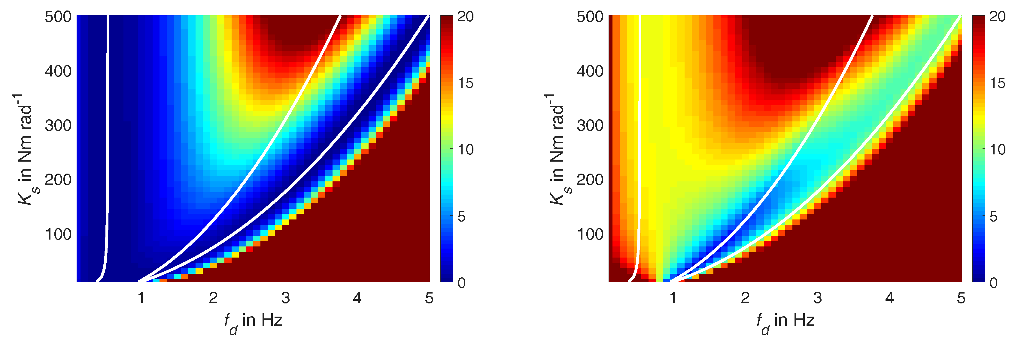
Figure 4.
Mapping between active length and antiresonance frequency.


Figure 6.
Simulation of adjustment to antiresonance while tracking a sinusoidal trajectory with 1.6 ; link (blue) and actuator (red) positions in upper plot, counter bearing positions middle plot, mechanical power in lower plot.
Figure 6.
Simulation of adjustment to antiresonance while tracking a sinusoidal trajectory with 1.6 ; link (blue) and actuator (red) positions in upper plot, counter bearing positions middle plot, mechanical power in lower plot.
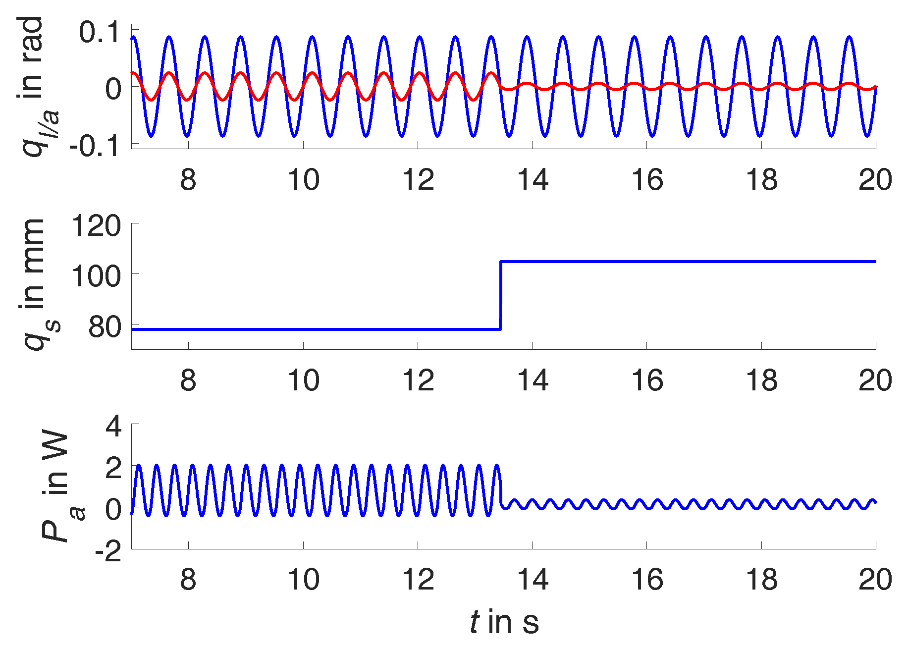
Figure 7.
Adjustment of stiffness while tracking different dual sinusoidal trajectories; link (blue) and actuator (red) positions; base trajectory: sine with 10 and 1.6 ; (top-left) superimposed by sine with 5, 0.8 ; (top-right) superimposed by sine with 5, 2.4 ; (bottom-left) superimposed by sine with 10, 0.8 ; (bottom-right) superimposed by sine with 10, 2.4 .

Figure 8.
Variable torsion stiffness actuator; partially disassembled (left) and assembled (right).

Figure 9.
Adjustment to antiresonance while tracking a sinusoidal trajectory with 1.6 ; link (blue) and actuator (red) positions in upper plot, desired (red) and current (blue) counter bearing positions middle plot, mechanical power in lower plot.
Figure 9.
Adjustment to antiresonance while tracking a sinusoidal trajectory with 1.6 ; link (blue) and actuator (red) positions in upper plot, desired (red) and current (blue) counter bearing positions middle plot, mechanical power in lower plot.
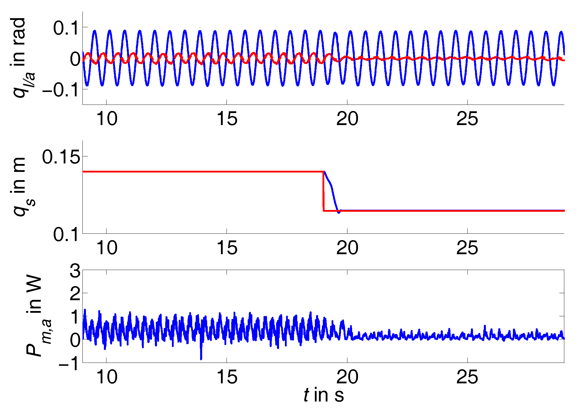
Figure 10.
Adjustment to antiresonance while tracking a dual sinusoidal trajectory with 0.8 and 1.6 ; link (blue) and actuator (red) positions in upper plot, desired (red) and current (blue) counter bearing positions middle plot, mechanical power in lower plot.
Figure 10.
Adjustment to antiresonance while tracking a dual sinusoidal trajectory with 0.8 and 1.6 ; link (blue) and actuator (red) positions in upper plot, desired (red) and current (blue) counter bearing positions middle plot, mechanical power in lower plot.

Figure 11.
Energy-frequency behavior (blue) for sinusoidal trajectories at 75 (left) and 150 (right); antiresonance (black) at 1.63 (left) and 2.17 , respectively.
Figure 11.
Energy-frequency behavior (blue) for sinusoidal trajectories at 75 (left) and 150 (right); antiresonance (black) at 1.63 (left) and 2.17 , respectively.

| Mechanical Properties | |||
|---|---|---|---|
| Inertia link | 0.94 | Inertia actuator | 1.15 |
| Mass link | 6.81 | Length link | 0.362 |
| Coulomb fric. coeff. link | 3.3 × 10⁻² | Coulomb fric. coeff. actuator | 2.4 |
| Viscous fric. coeff. | −0.8 | Stribeck fric. amplitude | 376.1 |
| Stribeck form factor | −0.13 | Stribeck friction velocity | 3.6 × 10⁴ |
| Gear ratio | 80 | ||
| Electrical Properties | |||
| Terminal resistance R | 0.4 Ω | Torque constant | 55 −1 |
| Terminal inductance L | 0.8 | Speed constant | 173.6 −1 |
© 2017 by the authors. Licensee MDPI, Basel, Switzerland. This article is an open access article distributed under the terms and conditions of the Creative Commons Attribution (CC BY) license (http://creativecommons.org/licenses/by/4.0/).
Share and Cite
MDPI and ACS Style
Beckerle, P.; Stuhlenmiller, F.; Rinderknecht, S. Stiffness Control of Variable Serial Elastic Actuators: Energy Efficiency through Exploitation of Natural Dynamics. Actuators 2017, 6, 28. https://doi.org/10.3390/act6040028
AMA Style
Beckerle P, Stuhlenmiller F, Rinderknecht S. Stiffness Control of Variable Serial Elastic Actuators: Energy Efficiency through Exploitation of Natural Dynamics. Actuators. 2017; 6(4):28. https://doi.org/10.3390/act6040028
Chicago/Turabian StyleBeckerle, Philipp, Florian Stuhlenmiller, and Stephan Rinderknecht. 2017. "Stiffness Control of Variable Serial Elastic Actuators: Energy Efficiency through Exploitation of Natural Dynamics" Actuators 6, no. 4: 28. https://doi.org/10.3390/act6040028
Note that from the first issue of 2016, this journal uses article numbers instead of page numbers. See further details here.