1. Introduction
Robots that are compatible with magnetic resonance imaging (MRI-compatible) will revolutionize the safety and efficiency of surgical operations by enhancing dexterity in a digitized imaging environment and providing precise positioning tools. By exploiting MRI, which is a versatile and indispensable imaging modality, these robots can enhance a surgeon’s dexterity and stamina by allowing superior spatial resolution and geometric accuracy [
1]. The excellent ability of MRI for localizing and robots for targeting pathologies will provide additional avenues for developing computational methods and MRI-guided interventions. Surgical instruments can be tracked in real-time while overcoming the deformation of tissues and the spatial constraints of high-resolution closed-bore MRI systems [
2]. However, to perform surgery safely with high precision and full controllability, robots must have accurate actuators operating inside the MR environment [
3,
4].
The applied force of the MR field causes displacement force and deflection torque, resulting in unwanted actuator motion that limits the accuracy of the actuated tool and increases the safety risk for patients. Interactions may result in serious injury or death to patients. Fatality due to the displacement of tools has been previously reported [
5]. The dislodgement of the robot’s end effector in tissues during MR-guided interventions is extremely hazardous, particularly if the end effector is located near important vascular or neural tissues or other critical tissues. Therefore, this study focuses on characterizing the force applied by the magnetic fields of a scanner on an ultrasonic motor (USM).
The effects of MR force fields on USM performance are not completely understood. For example, the applied displacement force and deflection torque have not been fully quantified for high-field (≥3 T) MRI systems. Consequently, in the context of safety, although actuators may not physically contact a patient’s organs, they are connected via links that can move the end effector inside the patient’s body. Therefore, unwanted dislodgement of the actuators can cause unpredictable dislodgment of other links and, consequently, of the end effector.
As we analyzed the force signals generated by the USM itself in our previous work [
6]. In that study, the generated axial force of the USM was evaluated. The current study focuses on the external force that is applied by the scanner on the USM. Most previous studies have concentrated on safety issues caused by displacement force and deflection torque because safety concerns have limited the use of MRI for many patients and with various devices. As reported in Scientific Reports in 2015, approximately 300,000 patients are denied MRI each year because of these limitations [
7]. Because the development of MRI-compatible tools is in a relatively early stage, the lack of knowledge regarding MRI-compatible tools and devices has resulted in the inability of patients to receive many possible benefits, including accurate diagnosis and treatment.
In addition, projectile effects account for 10% of MRI-related accidents; therefore, MRI safety regulations mandate the exclusion of many essential tools from the MR environment, including surgical robots [
8]. Projectile effects are not the only reason that conventional robots are banned from MR environments; unwanted movements of robot components also limit the accuracy of surgical operations. However, the precise operation of robots depends on accurate motion of actuators and the end effector. Only three types of actuators are MRI-compatible: hydraulic, pneumatic, and ultrasonic actuators.
USMs led to unsatisfactory results when they were first used in MRI. For example, USMs interacted with the MRI scanner, inducing noise in the images and generating heat. Lack of MRI compatibility led researchers to shift their focus from USMs to pneumatic actuators in the development of surgical robots for compatibility issues. Although pneumatic and hydraulic systems address a few of the compatibility issues, they cannot provide the numerous advantages of USMs. USMs are highly advantageous because they have a high degree of precision, small size and a non-magnetic mode of operation [
9].
However, unwanted motion of USMs limits their accuracy and increases the safety risk for patients [
10]. The effects of MRI force fields on motor performance are not fully known. For example, the applied force and torque have not been fully quantified for high-field (≥3 T) MRI systems. The risk of accidental dislodgement must be minimized because it can lead to morbidity or mortality. Although the actuators may not physically contact a patient’s organs, the actuators are connected via links that can move the end effector inside the patient’s body. Therefore, unwanted dislodgement of the actuators can cause unpredictable dislodgment of other links and, consequently, the end effector.
The force of attraction exerted by MRI on USMs has not been fully measured while such motors are running in their operational states, which include clockwise (CW) when the motor’s shaft rotates in clockwise direction, standby when the shaft is stalled, counterclockwise (CCW) when it rotates in the CCW direction, or when the motors themselves are in motion on the operating table under MRI.
It is imperative to assess the magnetic field attraction force on a USM to ascertain the potential risks and degree of compatibility with MRI [
5]. Engineering design criteria with effective safety standards can be established by quantifying the displacement force along with other effects of MRI on the motor, such as temperature changes, and the consequences for image quality [
11]. Assessment of the displacement force can also be used to formulate dynamics equations for robot mechanisms [
12,
13].
In addition, inclusion of the force applied by magnetic fields in dynamic equations (i.e., equations of motion) enhances computational accuracy in robot analysis, simulation, and control. The inclusion of this force is particularly important for enhancing the computational efficiency of complex robotic mechanisms operating at high speeds and for the real-time control of mechanisms and is also used in formulating algorithms for developing and implementing these mechanisms.
The displacement force should be measured to adjust the force errors caused by external forces (MRI) on the actuators. These errors can be used to adjust and control the force for tactile feedback systems. Displacement force information is also necessary to calibrate a tactile sensor [
14].
This study investigates the displacement force and torque applied to an ultrasonic motor at various bore locations using the designed apparatus presented in the Materials and Methods. The experimental outcomes are presented in the Results for three orientations of the motor inside the bore and for two states (on and off). The significance of the results and findings are discussed in the Discussion, and a brief conclusion, which integrates the results and discussion, is presented in the Conclusion.
2. Materials and Methods
Two types of movement of an object induced by a magnetic field were investigated: translational movement (displacement) and rotational movement (torque). These movements both result from the force applied by the static gradient field B0, the spatial gradient of the static magnetic field B0, and the spatial gradient field of the gradient coil.
The amplitude of the displacement force is proportional to the magnitude of the gradient field, and the maximum gradient field is present near the portal. The magnetic torque is a result of the magnetic field strength, and the amplitude of the torque is proportional to the field strength. The maximum field strength is present at the isocenter, where the gradient is nearly zero [
5].
The displacement force of the MRI fields was measured to quantify the effect of MRI on a USM. The displacement force needs to be calculated while the scanner is both off and on. This force was measured while the motor was in operation. The design of a measurement tool and the approach used to measure the force are described below.
2.1. Theoretical Evaluation
The maximum displacement force, applied force, and deflection torque can be calculated as follows [
15]:
where
is the volume of the object,
is the susceptibility difference, and
is the angle between the magnetization vector and the magnetic flux density (
). The constant,
, is referred to as the permeability of free space and has a value of
H/m. This model is for a spherical object that is sufficiently small that the following assumptions may be made: (i)
and
are constant values, and (ii)
is very small and has no effect on the field.
When a motor is placed in an MRI field, the spatial gradient of the static magnetic field,
, applies force and torque on the motor. Although
is constant (3 T) around the area of the isocenter, the magnitude of the magnetic field decreases as the distance from the isocenter increases. The fringe filed is the peripheral magnetic field outside the scanner bore. The scanners also have extra windings to minimize the stray field, i.e., a magnetic field whose intensity varies with distance to minimize the magnetic-field effects in the vicinity of the scanner for safety reasons. The spatial gradient is different from gradients generated by coils. The former gradient is generated by the static gradient of the magnet and is always present, whereas the latter is observed only during scanning. Because the MRI system must be confined to a specific area to minimize exposure of the public to the high magnetic field, the field outside the magnet is suppressed. Using this shielding technique generates a spatial gradient of the static magnetic field
in which the attraction force is exponentially increased. The spatial gradient of the gradient coil is a time-varying magnetic field generated by the coils for spatial encoding of the MRI signals during scanning [
16].
In the calculation of force and torque, the effects of “the spatial gradient of the gradient coil” are not fully known. These effects were experimentally analyzed in this study. However, the spatial gradient of the static magnetic field, , is considerably large and should be considered in the calculations. Its applied force results in dislodgement of a robot’s end effector.
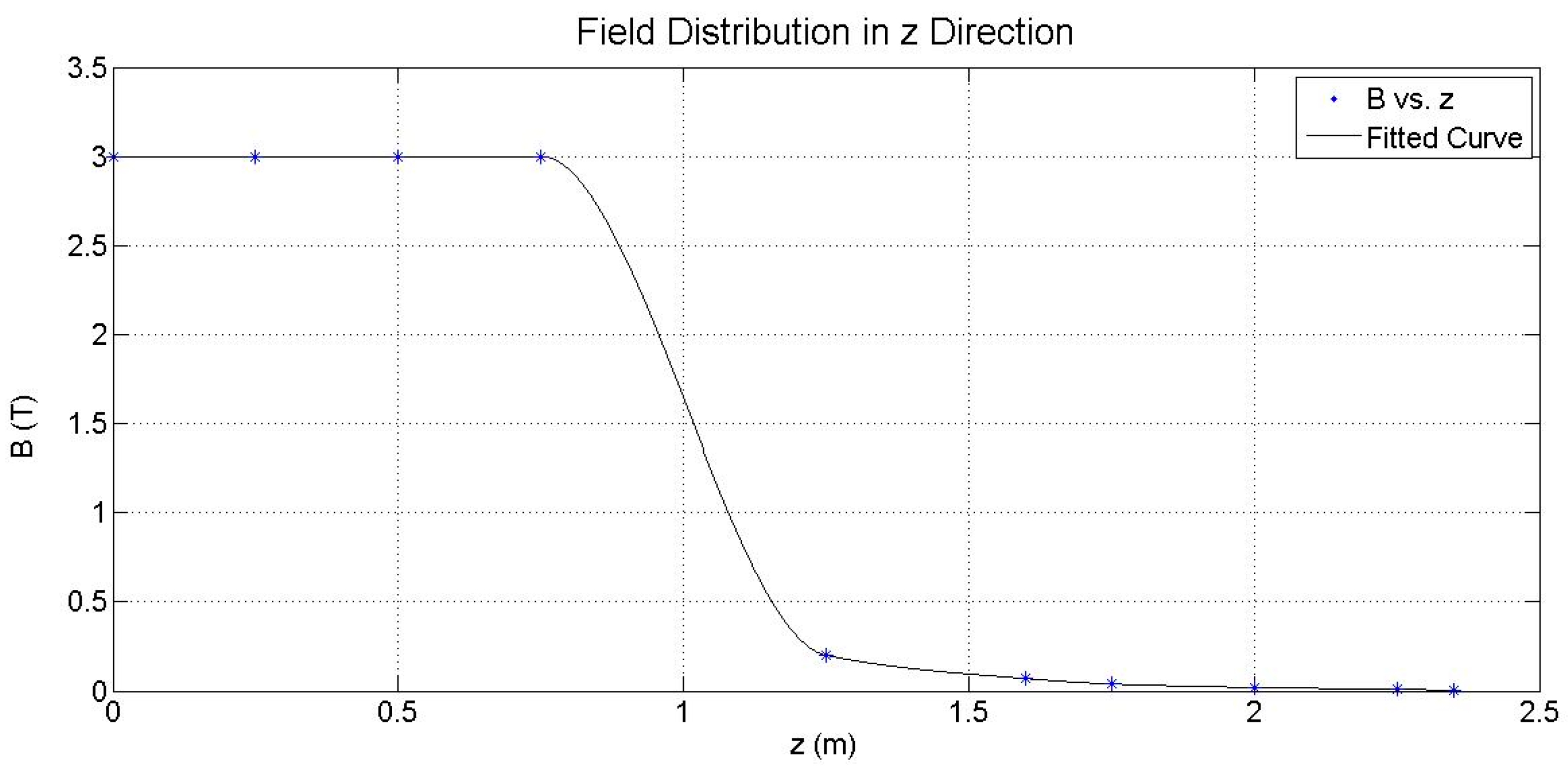
According to the specification of the field distribution of the 3 T Achieva system, which is given for few points around the scanner, the field distribution can be numerically approximated to evaluate force at the later stage using (1).
Figure 1 illustrates the approximated spatial (
) field distribution in the
z direction, that is, the bore axis. The
field distribution is used in (1) to calculate force. In
Figure 1, the field distribution specified by the 3 T Achieva system is indicated by stars, and the fitted curve is indicated by the solid line. The values of the field distribution inside the bore have not been provided by the manufacturer. Therefore, it was assumed that the magnetic field inside the bore is constant (approximately of 3 T). The variation of this value inside the bore has an insignificant impact on the force calculation independent of the manufacturing specifications. Interpolation via “piecewise cubic Hermite interpolating polynomial” was selected from the curve fitting toolbox of MATLAB 2013b to fit a curve to the given values in the
z direction. The fitted curve models the change in the field with an R-squared value of approximately 1. The approximated cubic polynomials derived through this model were used to calculate the force using (1). In this calculation, it was assumed that the field of approximately 3 T is homogeneous and steady inside the bore up to 75 cm from the center of the bore [
17]. The force at the isocenter is theoretically zero. The calculation was performed for the following four parts of the motor with considerable susceptibility: shaft, rear case, front case, and stator ring. Other parts of the motor were not included in these calculations because of their insignificant susceptibility.
Table 1 shows the material properties used for the theoretical evaluation.
The suggested formula is estimated for small objects that do not affect the external magnetic field. In theory, the effects of the induced magnetization of small objects on the external magnetic field can be ignored. In addition, the magnetic field is assumed to be theoretically infinite to obtain (1) and (2). However, the dimensions of the motor are not insignificant compared to the scanner’s magnet, and the motor perturbs the field. Therefore, the demagnetizing factor (known as the shape factor) should be considered in (1) to approximate the proper theoretical value of force. The motor shape was approximated by a sphere. Typically, the force is proportional to the inverse of the demagnetizing factor. A demagnetizing factor of
, reported for spheres, was used in this calculation because it has the largest impact on calculating force compared to other demagnetizing factors [
20].
Table 2 shows the total force applied to the motor.
The torque is theoretically evaluated using (2). The induced magnetization vector in the materials () and are in the same direction, and the angle is zero because the motor materials are assumed to be isotropic, i.e., the induced is parallel to the direction of the external field. Therefore, the deflection torque is zero.
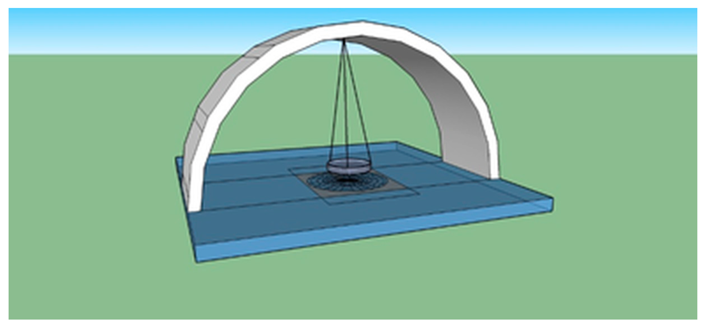
2.2. Suspension Apparatus
To measure the displacement force, a suspension apparatus was designed and implemented to support the motor in the MRI bore (
Figure 2). The apparatus was composed of an arch, a base frame, a plate, threads, a piece of graph paper, and a marker. The arch was installed on the base frame to stabilize the system. The plate was suspended from the center of the arch by three suture threads. To fix the position of the motor in the plate, the motor was placed in the plate filled with dough (Play-Doh). The marker was glued below the plate to indicate the deflection angle on the graph paper taped on the frame base.
The following MRI-compatible materials were used: a stainless-steel arch, a polyethylene terephthalate (PET) plate, silk suture threads, polar graph paper, a glass frame base, and a wooden marker. The dimensions were as follows. The plate was 6.5 cm in diameter with a depth of 1.5 cm, the threads were each 25 cm in length, and the height of the marker was 1 cm. The total height from the suspension node to the tip of marker was 27 cm. The plate and colored dough weighed 30 g. The motor system, including the motor itself, encoder, and part of the shielding, weighed 195 g. The plate, threads and marker weighed 5 g.
Polar graph paper was used to evaluate the deflection angle instead of the previously proposed wooden protractor [
21]. The polar graph was in concentric form at a distance of 3 mm and a radial distance of 5°. The distance between two concentric circles was divided into four segments. To reduce the complexity of the reading, the number of concentric circles was reduced to 22 with 12 primary spokes and 72 secondary spokes labeled in degrees.
This apparatus is advantageous compared with the proposed methods in [
11,
21]. The bulky motor (compared with the small volumes of implants or projectiles) can be placed on the spacious plate. The suspended plate can tolerate more weight than a suspension with only a single suture. The polar graph has a higher visual reading accuracy than a protractor. The reading error of the polar system is
, whereas that of a protractor is
. This measuring accuracy was obtained according to quarter divisions between the lines and circles on graph paper.
2.3. Approach
A USM, i.e., PUMR 40E (Piezoelectric Technology Co., Ltd., Seoul, Korea), was placed on the plate. The deflection angles were measured using a 3T Achieva scanner (Philips Healthcare, Best, The Netherlands). The deflection angle was evaluated by manual reading of the marker on the polar graph located at the bottom of apparatus (
Figure 2). An indicator was attached to the marker to indicate the rotation of the marker for torque measurements. The torque was measured about the axis perpendicular to the plane of the graph paper (
Figure 2). Rotations about the other two axes were measured as the deviations of the markers on the circles of the polar graph. The device was placed on the scanner tabletop on foam rubber (Philips Healthcare, Best, The Netherlands) to locate the motor at the level of the bore’s centerline because the field is purely axial with no tangential components along this line [
22]. The horizontal alignment of the frame base was also verified using a spirit level before beginning the experiment.
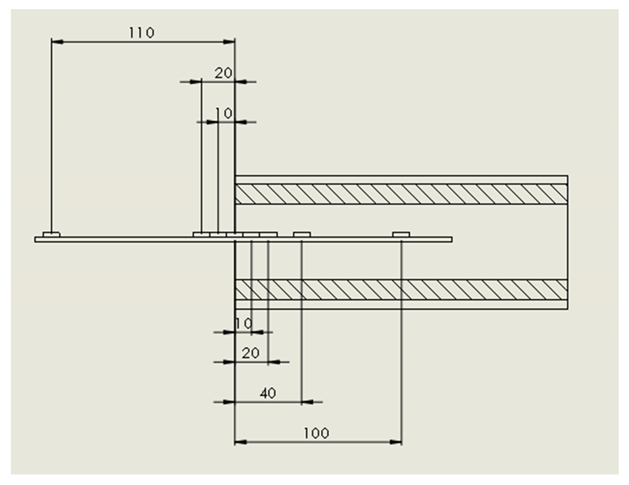
The deflection angle and rotation angle were measured along the bore’s centerline at eight locations (
Table 3 and
Figure 2). For each location, the experiment was performed at least three times by two observers [
11,
17]. Before each measurement, the apparatus was calibrated at an origin point 110 cm from the portal outside the bore, where no displacement was observed, and was carefully moved to the location of interest.
Additionally, the displacement force was measured on the cover surface of the scanner at the portal above the operating table, where the maximum spatial gradient of the static magnetic field B
0 was located in the 3 T Achieva system [
17]. The spatial gradient of the static magnetic field B0 specifies how steeply B
0 changes as a function of position. This quantity indicates the applied attraction force on metallic objects.
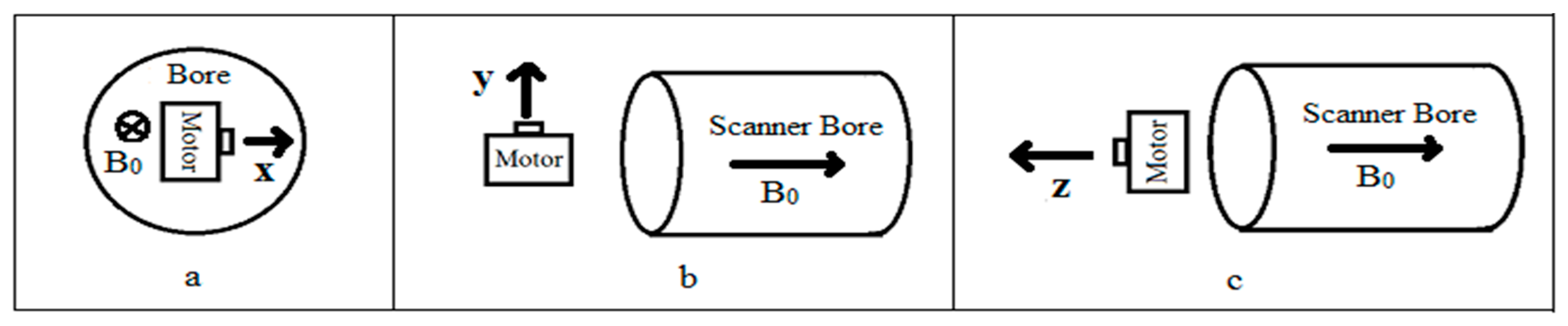
The motor was oriented in three directions: the
x-axis was parallel to the patient table and perpendicular to the bore axis, the
y-axis of the motor’s shaft was perpendicular to the patient table, and the
z-axis was parallel to the bore axis (
Figure 3).
2.4. Displacement Force Measurement
The displacement force was evaluated using (3), where
is the total mass of the motor system and the suspended part of the suspension apparatus (i.e., plate, marker, and dough). g is 9.8 m/s
2, and
is the deflection angle from the vertical axis. The sum of the suspended masses was considered in the force calculation. The error was measured by considering the total mass.
2.5. Deflection Torque Measurement
The torque was measured using the same method as in [
23] except that the system was placed at the center of the bore. The angle of rotation,
, was measured, and the torque was then calculated using (4). The angle of rotation was measured by evaluating the marker’s rotation along its axis on the suspension plate.
4. Discussion
The evaluated theoretical values, as shown in
Table 2, are within the same range as that of the experimental values.
Table 2 shows the theoretically evaluated forces, which were the target values for various locations inside the bore. The deviation between the evaluated theoretical and experimental values is due to several reasons. First, the magnetization factor was selected for a spherical shape as the maximum value of the shape factor. Second, the motor’s stator ring was approximated and its exact volume and material are not known. Third, the susceptibility of the materials was approximated for motor parts, which may be different in reality. Furthermore, the magnetic susceptibility of brass was estimated, as this value is not easily attainable and depends on the portions of its composites. Finally, owing to magnetization of the motor parts, internal forces exist among these parts, which were not considered in the theoretical calculations.
A static field applies an attractive force on metallic objects. The magnitude of this force is proportional to the magnitude of the magnetic field. The applied force on a motor depends on the structural composition and geometric shape of the motor’s metal components, such as the aluminum case, the brass shaft, and the internal metal components of the stator (conductor ring) and encoder. However, given the inaccessibility of most of these components and thus the difficulty associated with studying them, the interactions of the MRI and actuator were studied as a system, and the force was considered the total force applied to the motor’s center of mass.
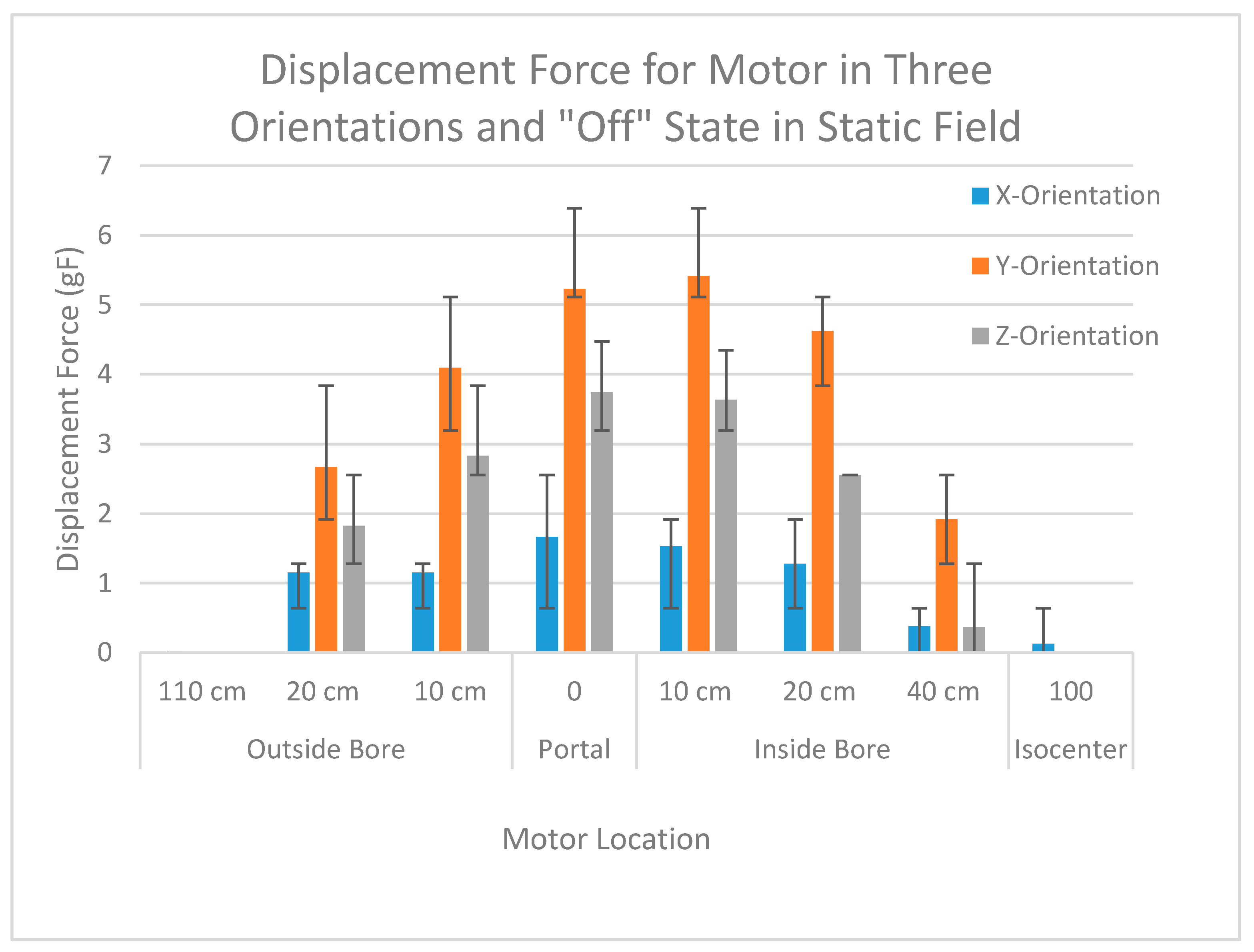
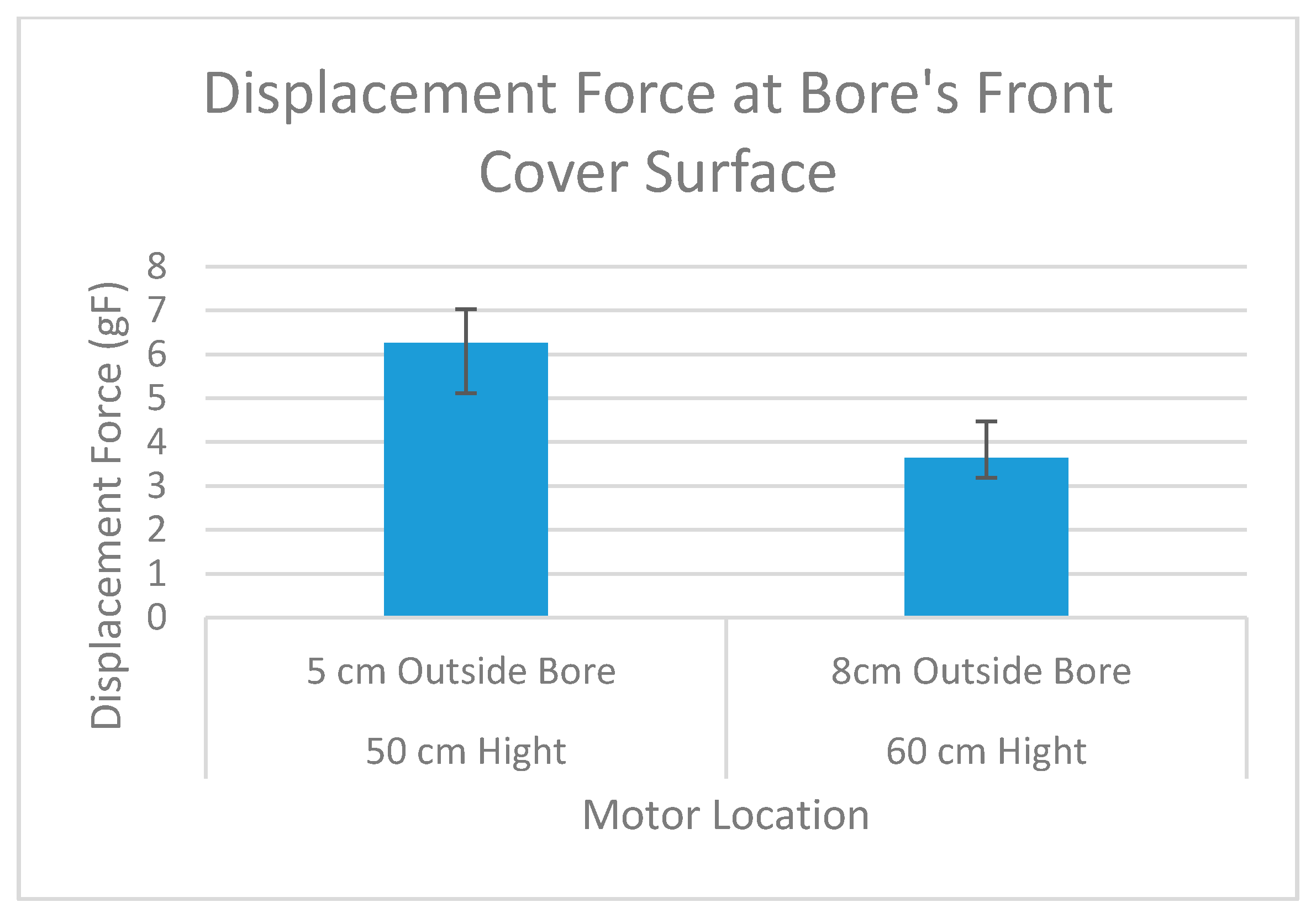
The maximum displacement force when the motor was not in motion was located between 10 cm outside the bore and 20 cm inside the bore. The displacement force was highest in this region because this is where the maximum gradient was present [
24]. The maximum force was not located at the portal, as had been theoretically expected. Our findings are supported by those of Kagestu, who also reported [
25] the possibility of the maximum gradient not occurring at the portal. Additionally, we found that the maximum displacement force was applied at the surface of the bore’s front cover (5 cm outside the bore at a height of 50 cm from the operating table) for the 3 T Achieva (Philips). However, the location of the maximum gradient and, consequently, the maximum displacement force might vary with the type of scanner.
The displacement force increased when the entire motor structure was moved. Increasing the speed of motion increased the displacement force applied to the motor by the MRI device. In this experiment, the maximum speed for moving the motor was limited to the maximum speed of the operating table. If the motor is used on a joint and moved with another actuator on a robot, motion speeds greater than the tested value would be possible and should be evaluated.
Although a deflection angle above 45° has been deemed a considerable force [
26] for testing ballistic objects and metal implants, such an angle would be too high for a motor because its mass is much greater than that of these objects. The mass of tested objects is on the order of hundreds of milligrams (e.g., a Drake aneurysm clip is 630 mg). Thus, when these objects are exposed to a high magnetic field, the deflection angle is high. However, the weight of the motor in this study was approximately 195 g, which is 100 times larger than the weights of these objects. Therefore, a small deflection angle (<1°) is considered a large force on the motor.
A cutoff force for the safety of motors placed in the MRI bore has not been reported. Nevertheless, the reported force of implants in [
27] provides a good reference. This study found that forces above 1 gF can be considered as high in terms of safety because the end effector of the actuated robot may come in contact with critical tissues during surgery. Implants generate a relatively small displacement force (e.g., 0.75 gF by a Drake aneurysm clip [
24]). Comparing the displacement forces reported in [
27] to the force applied to the motor, we conclude that the maximum displacement force (7 gF) on the motor is much larger than that reported for most implants. This force was theoretically calculated to be reduced to 2.1 gF or 0.7 gF when the volume of the brass and aluminum case was decreased by 1/4 or when the case was replaced with silicon carbide, respectively.
The agreement between the theoretical calculation and the experimental evaluation shows that the isotropic material assumption is valid. Although a small torque may exist, its value is insignificant. The possibility of having a significant torque was evaluated by randomly rotating the motor’s body inside the scanner. However, the symmetrical shape of the motor’s metal components results in a balanced force on the body of the motor, which is a potential reason for the insignificant torque.
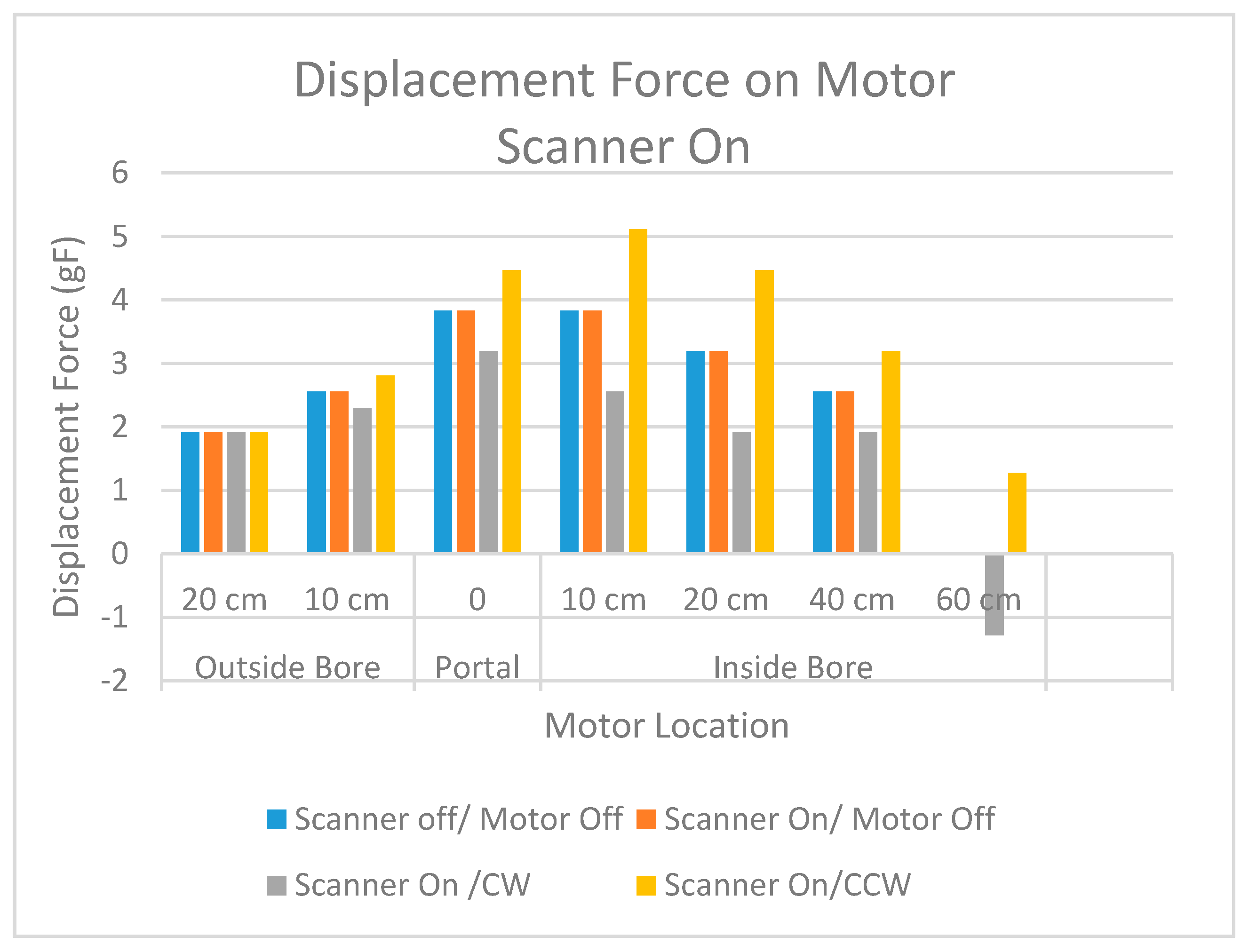
Running the motor alters the force by 1 gF. Running the motor in the CW and CCW directions causes attractive and repulsive forces on the motor of identical magnitudes in both directions. In some cases, the CW and CCW rotation directions showed different experimental results (
Table 4). This difference occurred because the static magnetic field applied different forces to the shaft of the rotating motor. The orientation of the shaft is not aligned with the direction of the static field when the motor is in the
x- or
y-orientation. In addition, the shape of the shaft is not completely symmetrical; i.e., there is a cut part on the cylindrical structure of the shaft. Consequently, different results may be observed even when the shaft is aligned with the
z-orientation.
The type of pulse sequence did not affect the displacement force. Turning the scanner on had an insignificant effect on the displacement force on the motor. There was no significant difference between the three image sequences, indicating that the spatial gradient of the gradient coil has insignificant effects on the force values. Additionally, the orientation of the scan did not affect the displacement force.
The minimum effective external force varies depending on the speed, weight, and arm length of the robot. In addition, the actuators are typically attached to the links, which are in motion or are not stabilized themselves. Therefore, the applied force on the links should be considered when solving dynamic equations for the robot.
We have studied other aspects of MR safety and MR compatibility of these motors. Quantitative analyses of temperature change, geometric distortions of MR images, and signal-noise-ratio of USM have been reported in [
28,
29,
30].


