1. Introduction
An interaction between a robot arm and humans represents an important issue in industrial and medical applications, which has to be safe and compliant during all probable situations, such as control failure, human error, or any unexpected error in the robot arm itself. On the other hand, the performance of the robot, including accuracy and rapidity, remains necessary as the task requirement [
1]. Tonietti, et al. [
2] explain that the machines must be safe against all conceivable accidents whilst they interact with humans. Another important target is their behaviour, which can frequently be expressed as a speed of motion. The designers used to consider the safety and the performance as two separate features [
3].
To overcome this problem, many sensors are used in the rigid robot arm and an active control is required. This solution is costly and not adequately dependable [
2].
Many types of variable stiffness actuators (VSA) have been presented during the last few years. Some of them reduced the probability of risk of injury. In spite of their excellent performance, rigidity is the main characteristic of this type of actuator. This led to the invention of sufficiently soft, high-stiffness actuators. In recent years there has been a substantial increase in designing, modelling, and constructing (biologically-based) continuum robots that provide new robotic behaviours, and offer an infinite number of robot applications [
4,
5]. The pneumatic muscle actuator (PMA), which is the base of such types of robots, has numerous positives over ordinary pneumatic cylinders, such as the high force in comparison to its weight, low workspace requirement, high flexibility to construct [
6,
7], adaptable installation possibilities, minimum consumption of compressed air, accessibility of different measurements, low cost, and being safe for human use [
6,
8]. For these exceptional features, the PMA has been considered as an appropriate actuator to use behind electrical and hydraulic actuators.
Despite its distinct positives, the PMA shows extremely nonlinear features [
9]. This nonlinearity is caused by the elastic-viscous properties of the inner rubber tube, the compressibility of air, and the structure of the complex behaviour of the PMA outer covering [
7]. Furthermore, the hysteresis performance is due to the inner rubber tube, which results in different performances of the PMA during different pressurizing conditions [
6]. This behaviour increases the complexity of the system model and its control [
4].
Numerous studies have been done to study and model the performances and the characteristics of such types of actuators. Among these studies, Takosoglu, et al. [
10] outline the static performance of the PMA. On the other hand, the Tondu and Lopez formula [
9] and the Chou and Hannaford model [
11] are extensively used. Both models are established on the theory of the virtual works of the cylindrical form and the zero walls of the inner rubber tube and the braided sleeve. Their force formulas have been modified many times to reduce the error between the theoretical and exact force values. The force formula has been enhanced by Al-Ibadi, et al. [
12] by considering the amount of the pressure required to establish the tensile force. The hysteresis has been considered by numerous researchers [
13,
14]. In spite of these works, an exact force and position model do not yet exist. As a result, the control strategies have to be modified to overcome the difficulties for the single actuator, as well as for the multiple PMAs.
In this article, two of the major previous assumptions are considered, the thickness of the actuator and the friction between the inner rubber tube and the braided sleeve. A general structure-based force formula for the contraction actuator is presented, and then a modification of the previous length formula is generalized. Furthermore, the variable stiffness of the inner tube has been clarified it is influencing to the stiffness of the PMA at variety pressurised conditions.
2. Structure of the Pneumatic Muscle Actuator
Joseph L. McKibben, in the 1950s, developed the pneumatic muscle actuator (PMA), which is simply made from a latex tube bounded by an expandable sleeve [
11]. The simplicity of the McKibben artificial actuator structure presented its use in many applications. Its operational basics are simple: the bounded tension of the inner rubber tube is converted into a vertical pulling force [
15]. Different air pressure produces different pulling force values and this axial force is subject to the construction of the PMA
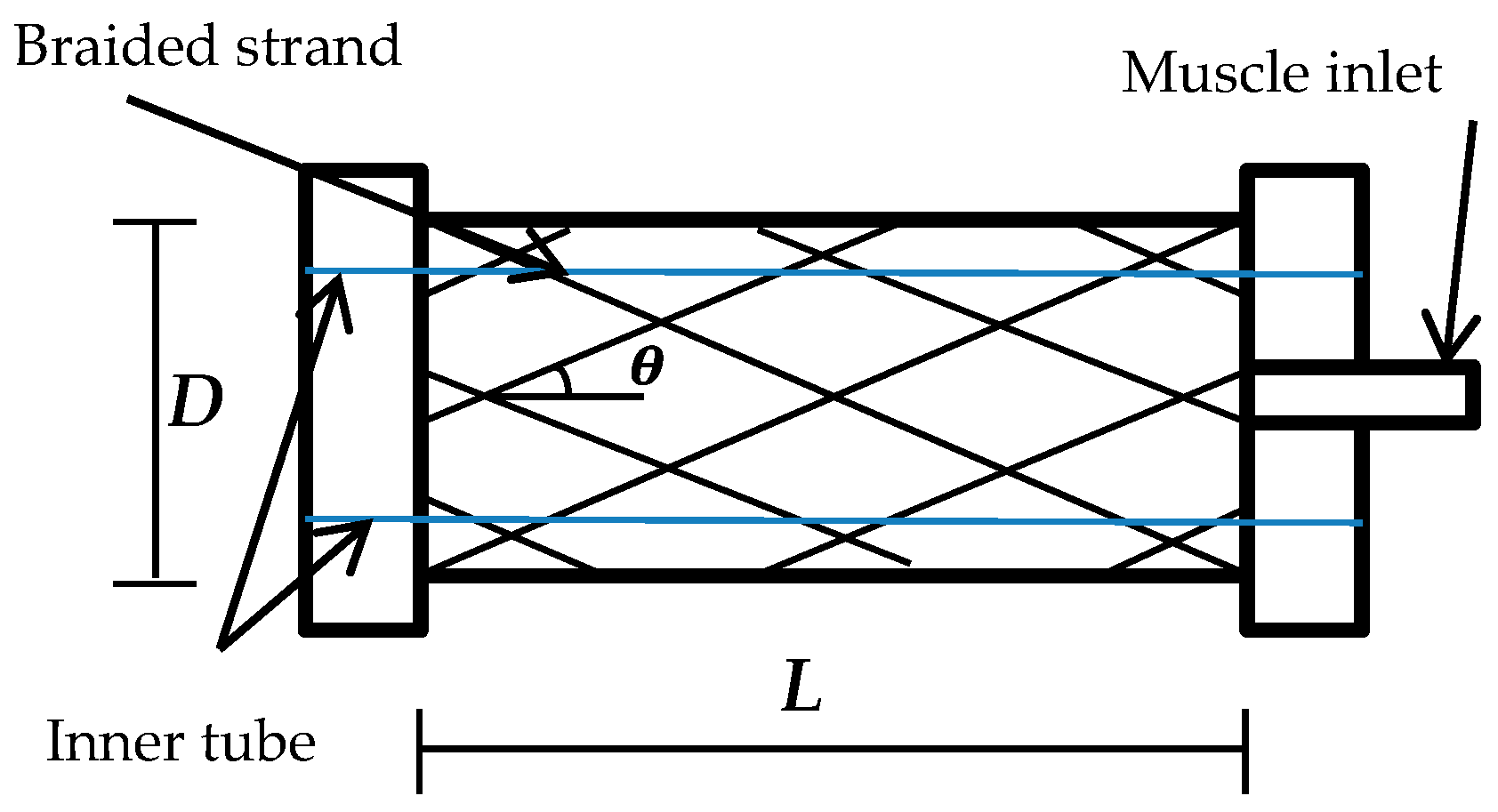
Figure 1 shows the general construction of the pneumatic muscle actuator.
Where L is the length of the actuator, D is the diameter, and θ denotes the braided angle, which it is measured between braided strand (b) and the vertical line, its value varies from 0° to 180° based on the construction and is the main aspect in the PMA’s actions. The initial values are defined as L0, D0, and θ0, respectively.
The length, diameter, and the braided angle change with the amount of the air pressure inside the muscle until the braided angle reaches 54.7°, which represents the critical value at which the contraction force is zero [
9,
11,
12].
The contraction pneumatic muscle actuators act similarly to biological muscle: the contraction behaviour occurs when the diameter of the inner rubber tube increases due to the air pressure, which leads to producing a specific amount of pulling force.
3. Operation of the PMA
The principle operation of the contraction pneumatic muscle can be fully explained in two situations: (a) variable air pressure at a fixed, attached load; and (b) varying the load with constant air pressure. The diameter of the braided sleeve will increase and, as a result, the diameter of the PMA rises by incrementing the air pressure, while the actuator length will decline to reach the maximum contraction ratio (
ε). Equation (1) gives the contraction ratio expression:
where
L0 is the initial actuator length and
L is the length of the PMA under the pressurised condition.
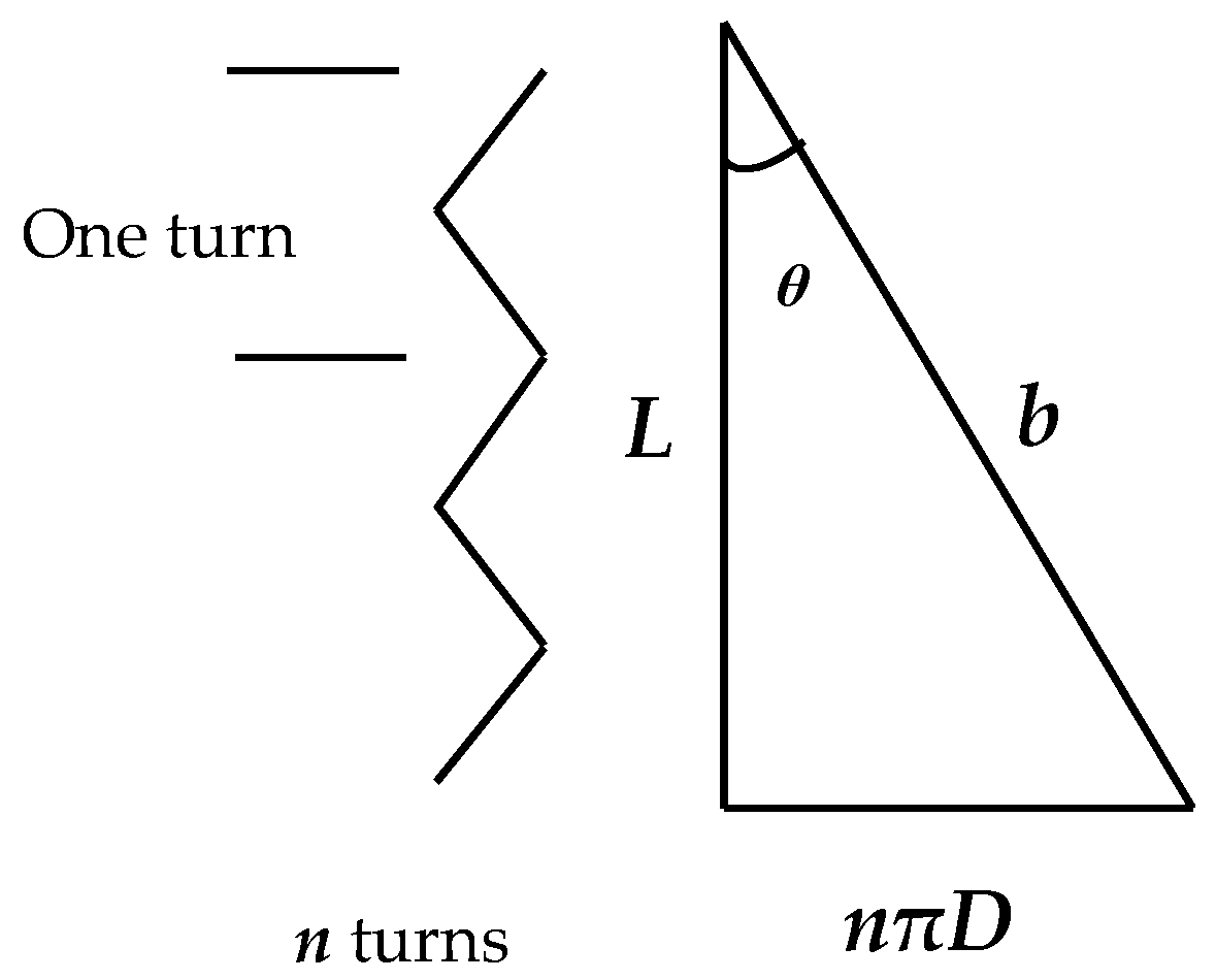
In
Figure 2,
n represent the total amount of strand turns for the whole actuator.
n is a constant value for each actuator and it depends on the length and specification of the braided sleeve. The other coefficients, such as
L,
D, and
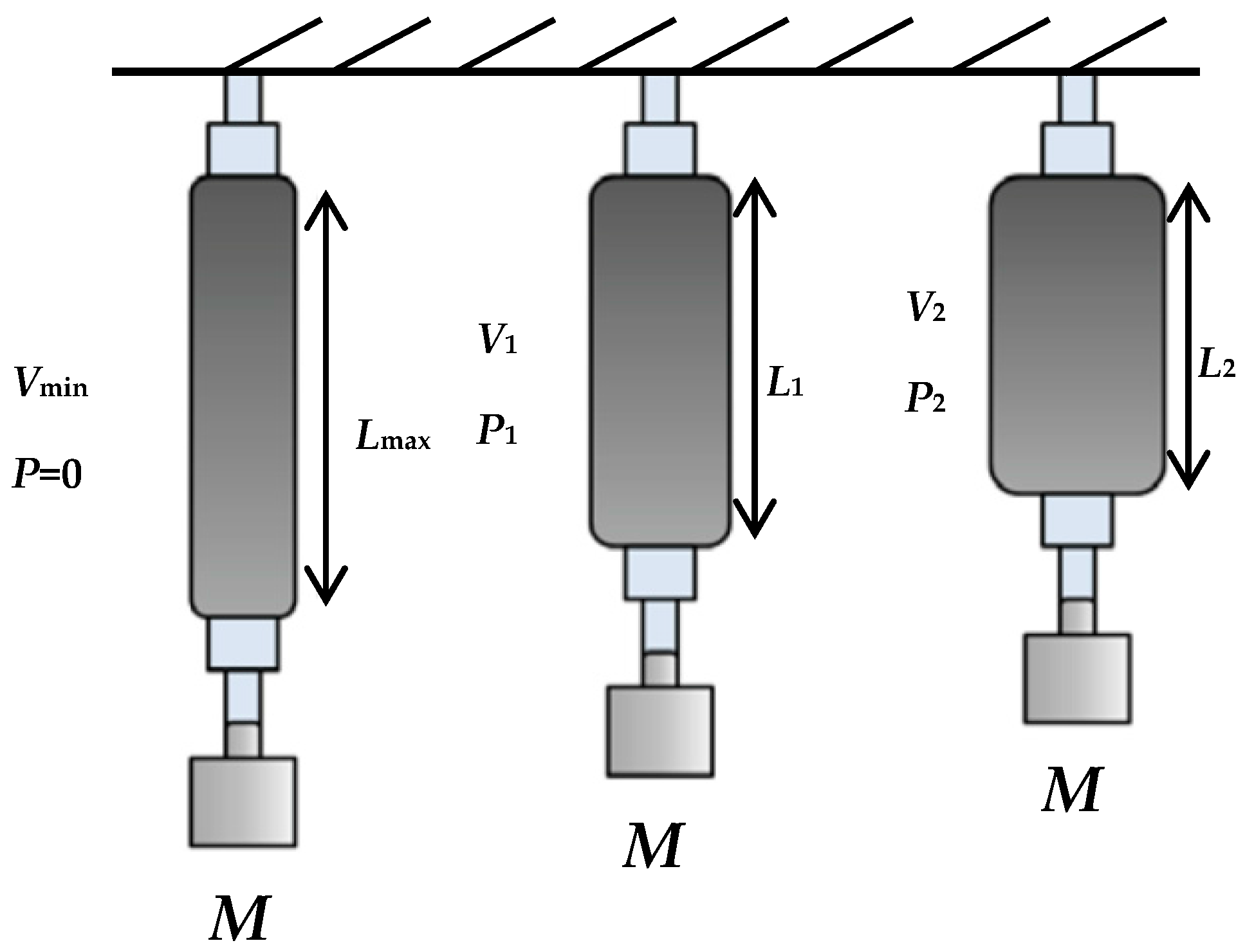
θ, are varied due to the amount of air pressure and the construction of the air muscle. In the first operation, as is shown in
Figure 3, the actuator is fixed at the upper end and a specific load is attached to its free end. The air pressure slowly increases from zero bar to a certain value. Due to the similarity between the pneumatic muscle and the biological muscle, the contraction in the first operation is called isotonic, and measuring the contraction at the second operation is called isobaric [
10].
At a definite pressure value
P1, a contracting force will start to lift the fixed load until it reaches the balance point; at this point the contraction force is similar to the mass weight [
16].
The volume of the PMA will rise to V1 and the length reduces to L1. An increment in the pressure to P2 leads to an increase in the actuator’s volume and creates more contraction to L2, and the air pressure will increase to its maximum value which is subject to the structure of the actuator.
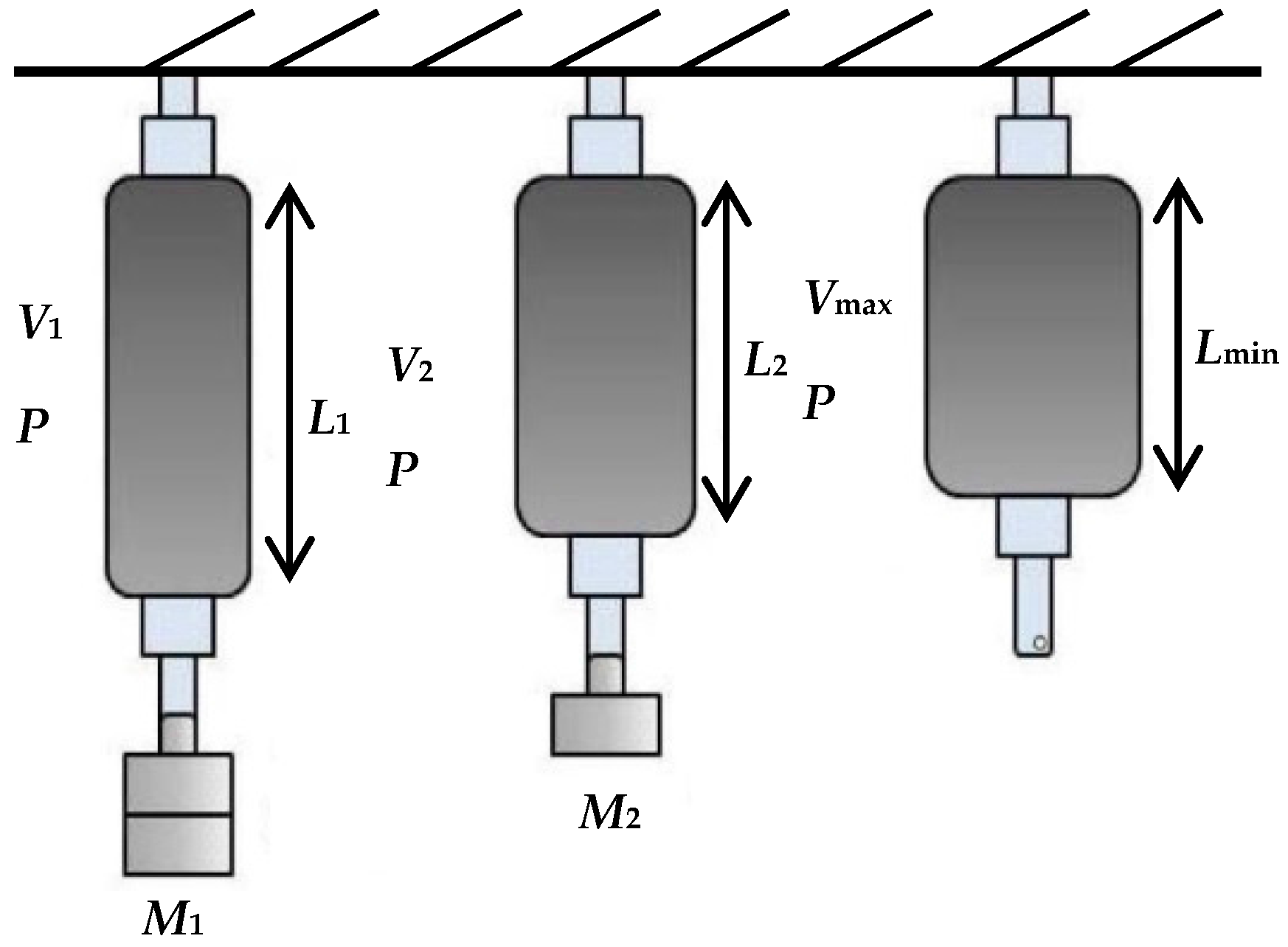
The second action situation is pressurising the PMA at constant air pressure
P. Varying the attached load, as shown in
Figure 4, leads to changes in the behaviour of the PMA. Reducing the load from
M1 to
M2, and then to no load, will raise the volume and reduce the length of the actuator [
16]. The multiple lengths and volumes produced depend on the amount of the air pressure inside the muscle.
4. Presented Force Formula
Tatlicioglu, et al. [
17] show that, in most engineering systems, it is important to have an accurate model to improve the behaviour of the system. In recent years there have been numerous studies conducted to mathematically model the PMAs. The work was done to relate both the air pressure and the length of the PMA to the generated pulling force of contraction muscles. Numerous factors have major effects on the model, such as the properties of the material used in the PMA construction, length, diameter, braided angle, and air pressure. Understanding the relationship between these factors leads to constructing accurate models, especially for control requirements [
16].
Important work was done by Chou and Hannaford [
11]. They constructed a model for the contraction pneumatic muscle actuator under the following assumptions: (a) the shape of an actuator is cylindrical; (b) there is always a contact between the braided sleeve and the surface of the inner tube; (c) neglecting the friction between the tube and the braided sleeve; and (d) ignoring the latex forces of the tube.
The second widely-used model was formulated by Tondu and Lopez [
9]. Their contraction force formula was derived under the following assumptions: (a) the shape of the PMA is a perfect cylinder with zero wall thickness; (b) there is contact between the inner rubber tube and the braided sleeve; (c) the braided strand length is constant; (d) there is no friction between the tube and the sleeve; and (e) the latex tube force is neglected.
Other research is being conducted to overcome the above assumptions for the presented contractor force models. Tondu and Lopez [
9] modified their model by adding the shape correction factor (
q ≤ 1).
There are two options to select the correction factor: (a) the constant value, which depends on the material, and (b) the variable value, which depends on the pressure.
Kang, et al. [
18] propose a formula to the correction factor as follows:
where
c1 and
c2 are positive constants. From this equation, the correction factor becomes 1 at maximum air pressure, where the actuator shape is cylindrical.
Al-Ibadi, et al. [
12] argue that the pulling force of the contractor PMA does not generate an air pressure value less than, or equal to, 0.45 bar.
Referring to
Figure 3, and under the virtual work theory, the input work (
Win) for the McKibben’s muscle under air pressure supply is:
where
dV is the volume change. The output work (
Wout) occurs when the actuator shortens with the volume change:
where
F is the contractor (tensile) force and
L is the axial (actuator) length. Assuming the lossless actuator has no stored energy, the input work must equal the output work as assumed before, then:
thus:
or:
The authors have assumed that the braided strand (
b) length fixed during the pressurising process, and the volume of the actuator under cylindrical shape assumption is:
Referring to the assumption above for the Chou and Hannaford [
11], the Tondu and Lopez [
9] model, the type of material and its thickness and, as a result, its stiffness, plays a major factor in the force production. For that reason, the volume of the actuator is defined as follows:
and:
where
V is the volume in m
3,
Din is the inner diameter in m,
L is the length of the PMA in m,
Dout is the outer diameter in m, and
ThD is twice the value of both the inner rubber tube and the braided sleeve thickness.
Figure 5 shows the cross-section of the actuator structure.
From Equations (8) and (9) the volume of the PMA is less than the volume of the actuator in Equation (7). Moreover, the Win will be less and depends on the thickness of the rubber tube and the braided sleeve. Increasing the rubber tube stiffness leads to increase its resistance and the Wout will decrease, while the generated pulling force affects it longitudinally.
The resistance force is defined as follows:
where
frs is the resistance force (N) of the rubber tube,
sr is the stiffness (N/m) of the rubber tube,
Ain (m
2) is the inner area of the rubber cross-section, and
ΔL (m) is the change of the actuator length between the initial length and length at each pressure step.
The losses force due to a contactless between the surfaces of the rubber tube and the braided sleeve is found experimentally as shown in Equation (11):
The experiment to find the expression in Equation (11) has been performed as follows:
An air pressure is applied to the actuator in
Table 1 with step values from 0 to 5 bar.
At each step, the input work is calculated from Equations (3) and (8).
Subtracting the losses due to the stiffness and the changing in the inner area using Equation (10).
Calculating the output work by multiply the pulling force of the actuator by the length change of Equation (4) (see
Figure 6).
Repeat this experiment on different actuators.
Fixed value of work losses are found to be about 0.641 Nm and it is considered to be due to the contactless losses between the inner tube and the braided sleeve, and the force losses decrease when the () increases (i.e., the contact occurs when the pressure is increased).
Under the principle of virtual work, the pulling force
F can be defined as follows:
where
ΔV represents the volume change between the initial and new value each time the pressure is changed.
To validate this equation, a 20 cm contraction actuator has been built to the specifications shown in
Table 1.
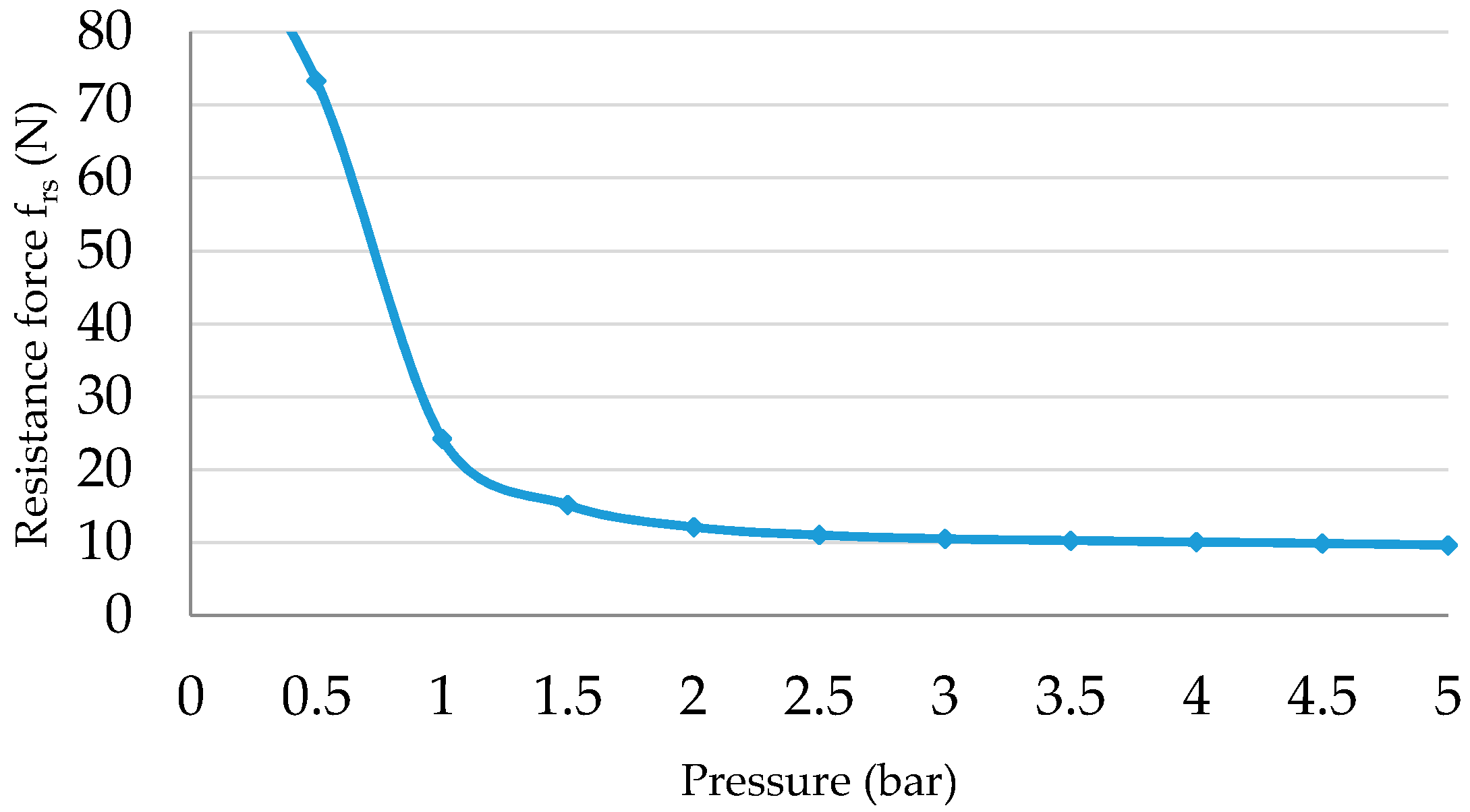
The actuator is pressurised from zero to 5 bar by 0.5 bar steps; at each step, the length of the PMA is recorded. From Equation (10), the resistance force of the inner rubber tube is illustrated in
Figure 7, as a function of the input pressure.
Figure 7 shows that the resistance force is very high at low-pressure values (
Pg < 0.5 bar) and its value has been decreased dramatically at
Pg = 0.5 bar.
The contactless losses at each air pressure step are also calculated and are illustrated against the pressure in
Figure 8. The friction value at
Pg < 0.5 bar is significantly high.
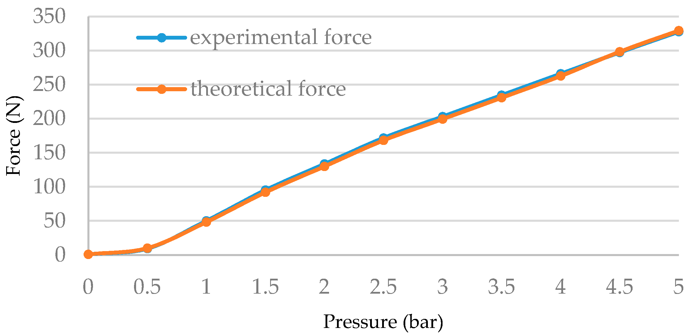
Figure 9 shows the force of both the experimental and theoretical pulling force and it is explained that there is a substantial matching between them.
Since the value of frs and fc is high at Pg < 0.5 bar, the pulling force F cannot be produced and the generated force increases when the opposing forces are decreased.
To ensure that the Equation (12) can fit for all contraction actuators, another actuator for the specification in
Table 2 is constructed.
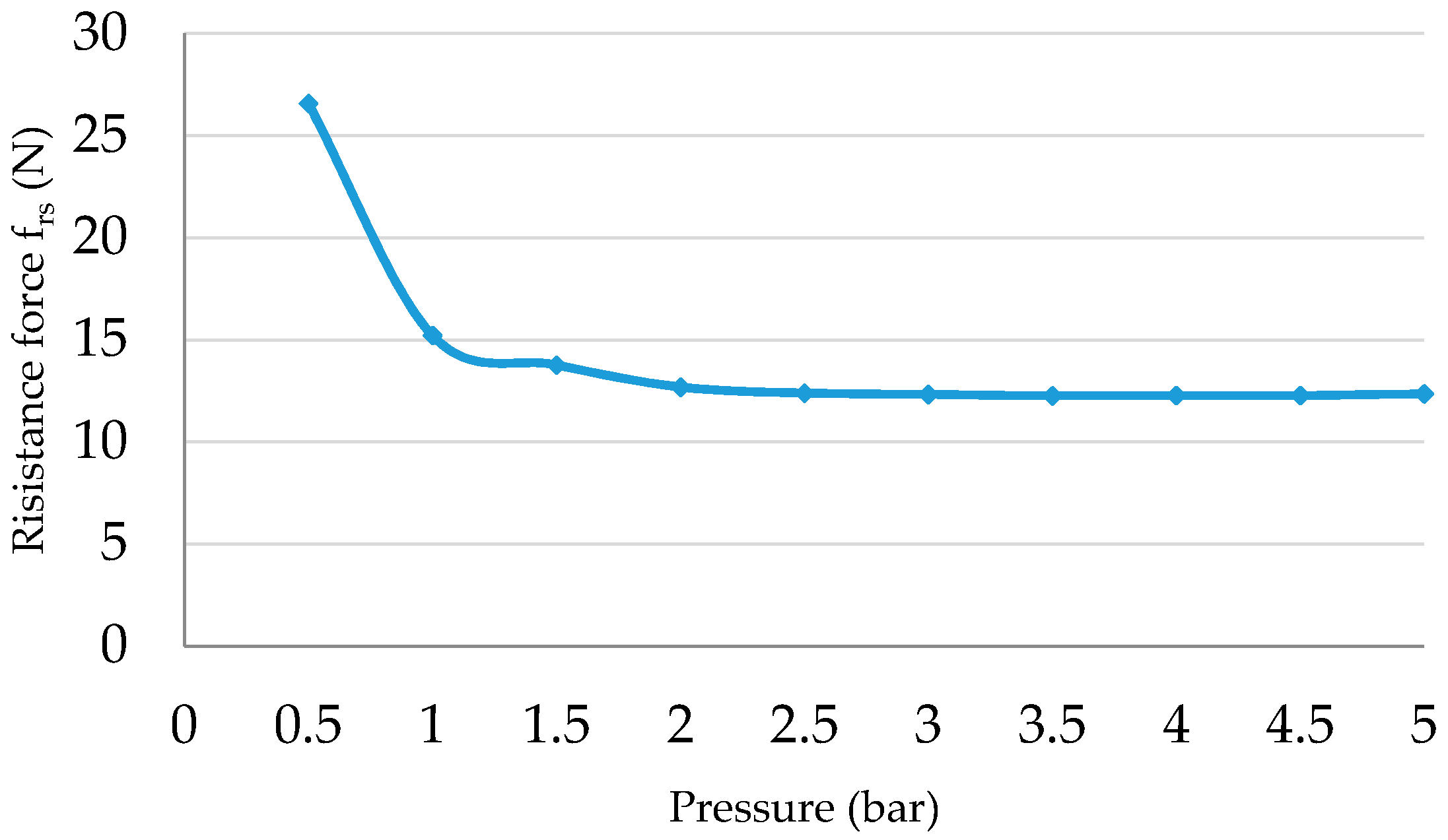
The contactless losses (
fc) for this muscle have the same values as the pressure seen in
Figure 8, while the resistance force (
frs) is different because it is dependent on the rubber’s stiffness.
Figure 10 shows the resistance force against the air pressure. The force of this actuator is higher than the force of the first PMA while the losses are increased because the stiffness is increased.
Increasing the stiffness of the rubber leads to increasing the resistive force, on the other hand, it decreases the contraction ratio (ε) and, as a result, the input work will be higher.
The two PMAs above are made from the same rubber tube diameter, but with different stiffness values. Therefore, to further verification, an actuator is made to the specifications listed in
Table 3.
The reduced forces due to contactless losses have almost the same values because the material types are the same for both the rubber and the sleeve, whereas the resistance force is different because of the differences in diameter and stiffness of the actuators. From Equation (10) the
frs can be given as in
Figure 11. The mean square error (MSE) is listed in
Table 4 and gives the error between the experimental and the proposed force formula to the actuators understudy for the pressure steps from 0 to 0.5 bar and it is calculated according to Equation (13):
where
k is the sample numbers and
e is the error between the experimental and the theoretical values.
Figure 9 and the
Table 4 verify that the proposed force formula in Equation (12) can be used for a variety of actuators, which differ in rubber stiffness and inner diameter.
5. Structure-Based Length Formula for Contraction PMAs
The length of the contraction PMA decreases, while the applied pressure is raised. However, the contraction ratio (
ε) is not fixed for all actuators and it depends on the type of inner rubber tube, the diameter of the PMA, and the maximum diameter of the braided sleeve. Al-Ibadi, et al. [
12] proposed a length formula as in Equation (14).
Their formula is derived for a range of actuator lengths, from 0.15 m to 0.4 m. Furthermore, similar rubber tube and actuator diameters have been used:
where:
.
where: the parameters
a,
b,
c,
d, and
e are constants for each
L0 and they represent the coefficients of Equation (14).
To present an efficient length formula that is able to track the actual length of the PMA, the initial length (
L0), initial diameter (
D0), and the rubber stiffness must be considered. While the contraction ratio increases as a pressure increase, and the highest rubber stiffness
sr leads to the lowest stretchable ability, then:
and to avoid dividing by zero, an exponential form will be considered as follows:
where
a and
b are constants for a fixed structure and the expression to find them depends on the diameter and stiffness of the PMA.
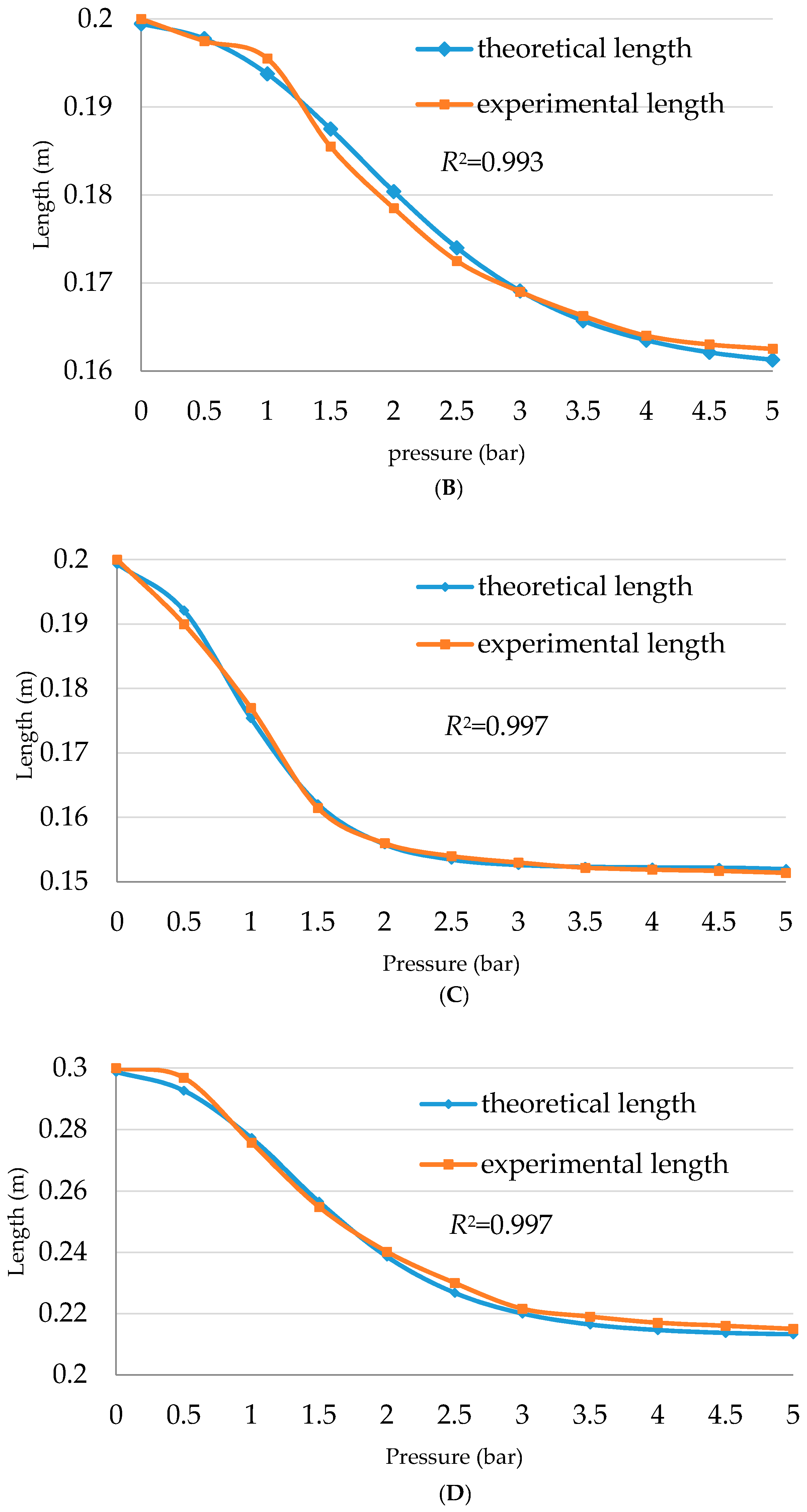
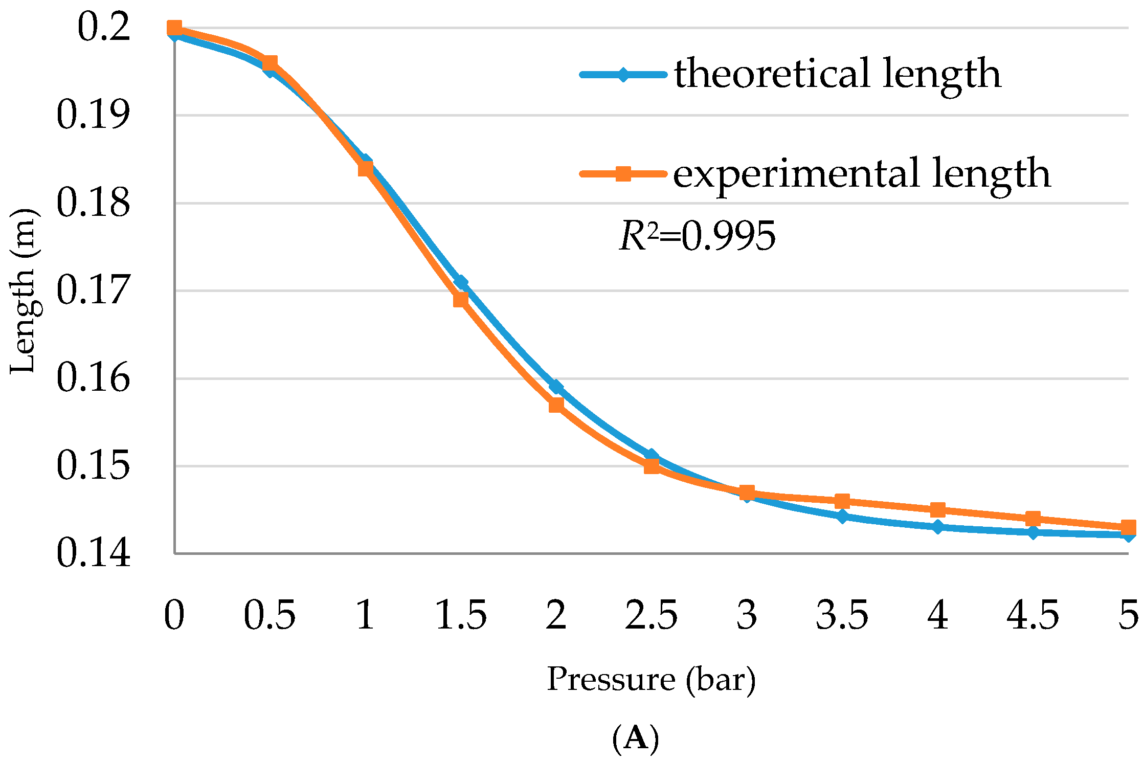
To improve the efficiency of this equation, four actuators are made to the specifications listed in
Table 5 and
Figure 12 illustrates the theoretical and the experimental data according to Equation (17).
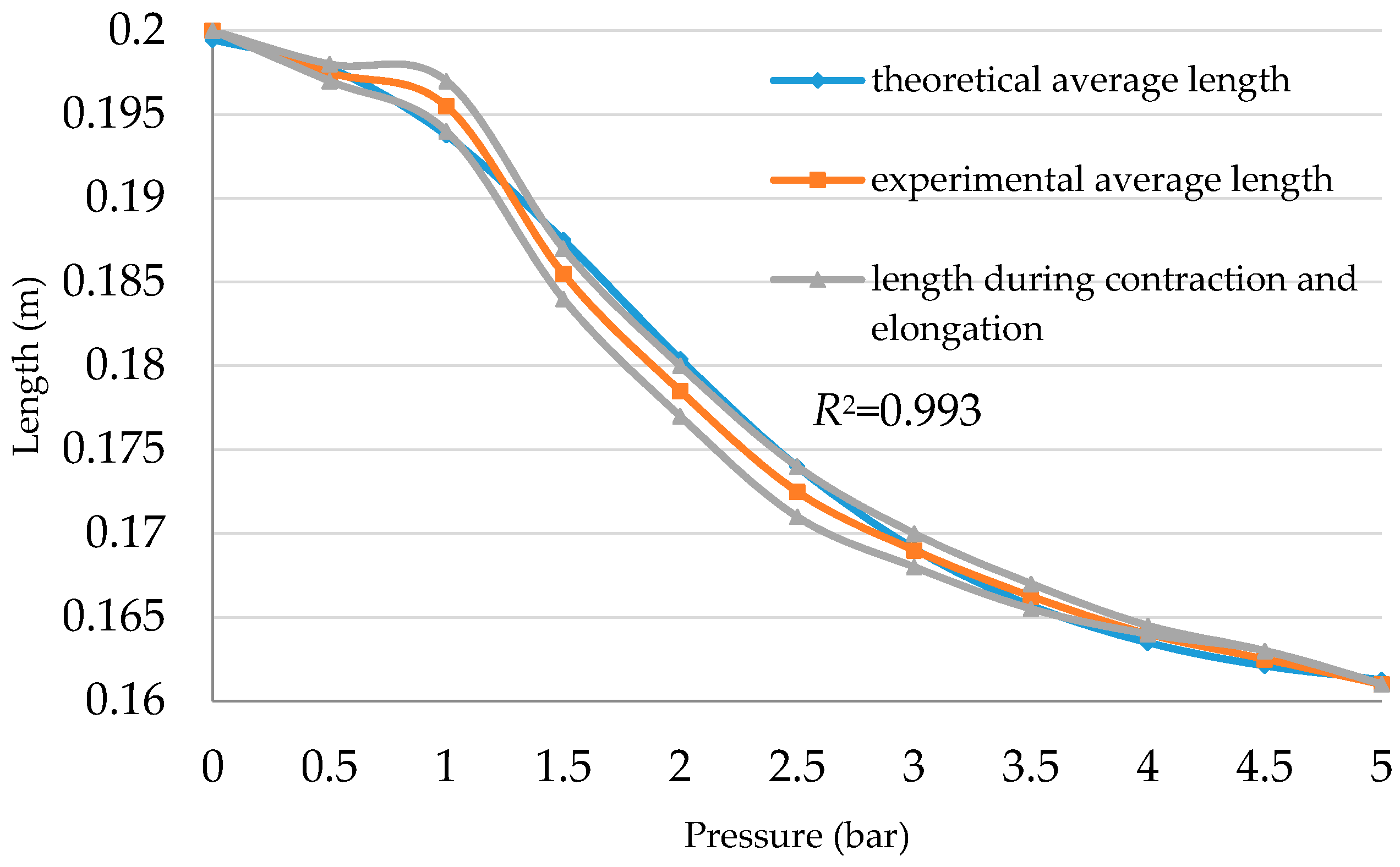
While the experimental length is recorded as an average for the length during contraction and elongation, the small deviation remains inside the whole curve.
As an example,
Figure 13 shows the length of the actuator
B with a contraction and elongation curve.
The length formula in Equation (17) can be used in Equation (12) at any air pressure value to detect the contractor force. Furthermore, the position of a single actuator can be defined at any time for all PMAs under their structure specification.
Sárosi, et al. [
19] argue that the maximum contraction ratio is about 25%. However, from Equation (17), and as illustrated in
Figure 12, the contraction ratio depends on the stiffness and diameter of the actuator and is not fixed.
Table 6 lists the contraction ratio of the actuators (
A,
B,
C, and
D), which are according to the specifications given in
Table 5.
Table 6 shows that the contraction ratio has an inverse relationship with the stiffness of the inner rubber tube, where both
A and
D actuators have similar values of the contraction ration, while it decreased for the actuator
C, whereas actuator
B has the minimum contraction ratio (see
Table 5).
Since Equation (17) is derived from fitting the length of the actuator at no-load,
Table 7 lists the MSE at different load values for the 20 cm contraction PMA, fit for centimetres, for 11 steps of pressure from 0 to 0.5 bar.
7. Conclusions
Modelling the nonlinear system, such as that of the pneumatic muscle actuator (PMA) is a challenge and has three major performances; contraction, pulling force, and variable stiffness. An efficient model must describe the full mechanical behaviour. Since the McKibben artificial muscle is applicable for structure differences, the most effective model has to be based on the structure coefficients, such as initial length, initial inner diameter, the thickness of both the inner rubber tube and the braided sleeve and the stiffness of the rubber tube or, in other words, its ability to extend.
In this article, numerous contraction actuators are built with different structural factors. The presented force model, which is based on these parameters, is validated. Moreover, the results show that this model might be considered a general force formula to the contraction PMA, whatever the structure. On the other hand, it overcame two of the previous assumptions: the zero wall thickness, and ignoring the friction. These have a significant impact on the actuator force, especially at low air pressure values.
The contraction length formula has been generalised in this paper in comparison with the previous work in [
12], which depended on the initial actuator length for similar inner tube performances. The new formula is validated to different contraction actuators and it has been formulated to fit various constructions. The proposed actuator length formula has been derived from the no-load condition, then, it is validated to different load values.
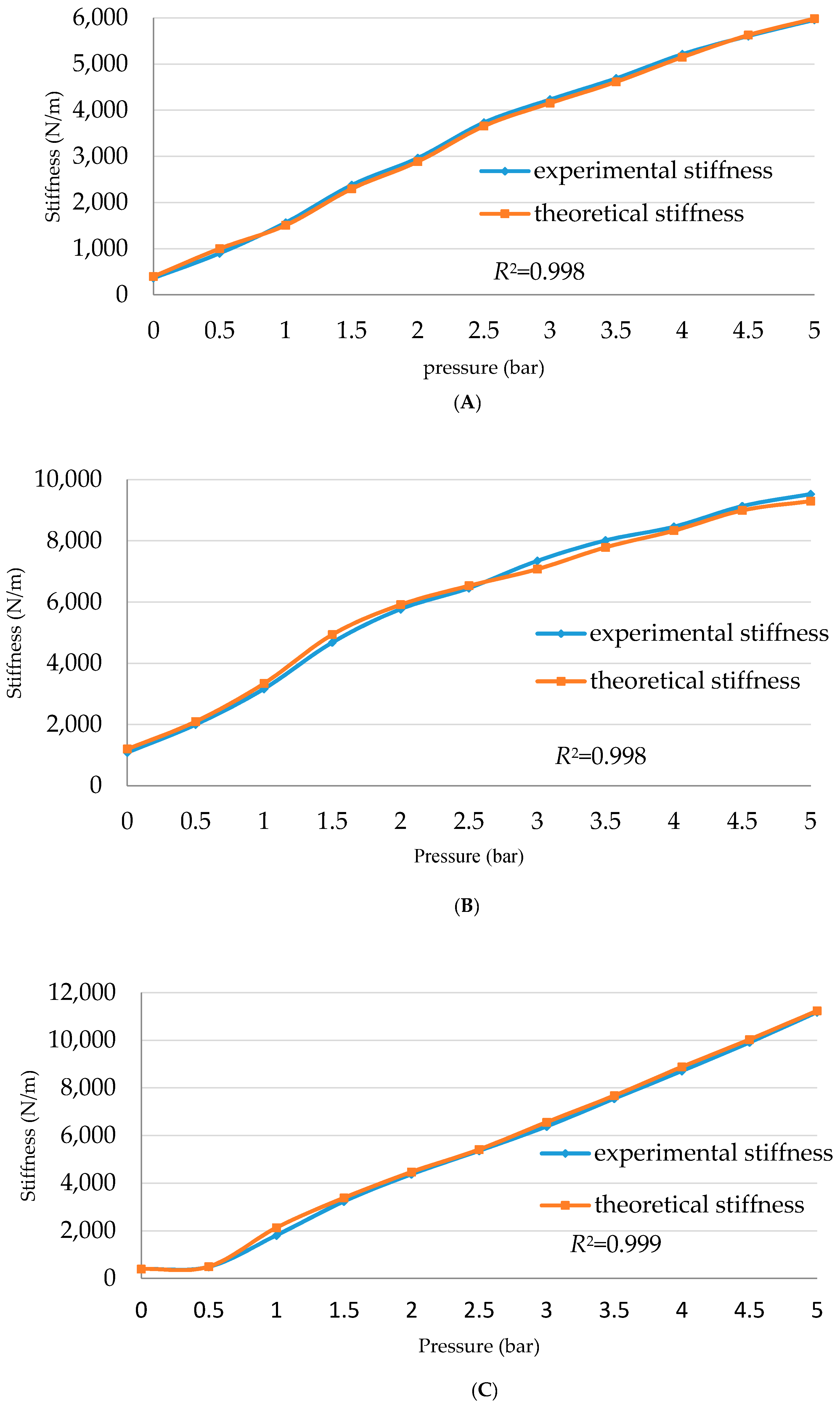
A general stiffness formula for the contraction PMA has been defined and verified for the PMAs under study. The result has proved the effectiveness of the structure on the PMA stiffness.
These models cause the control of force, contraction length (end position) and the stiffness to easily and clearly describe the behaviour of the contraction PMAs under pressurised conditions, which helps in choosing a suitable structure for the required application.
As a future project, a suitable structure will be selected to design and build an efficient continuum arm for different applications, as well as design the proper control system which depends on the muscle parameters.


