Modeling a Pull-In Instability in Micro-Machined Hybrid Contactless Suspension


The Institute of Microstructure Technology, Karlsruhe Institute of Technology, Hermann-von-Helmholtz-Platz 1, 76344 Eggenstein-Leopoldshafen, Germany
*
Author to whom correspondence should be addressed.
Actuators 2018, 7(1), 11; https://doi.org/10.3390/act7010011
Submission received: 26 February 2018
/
Revised: 16 March 2018
/
Accepted: 16 March 2018
/
Published: 20 March 2018
(This article belongs to the Special Issue Micromanipulation)
Abstract
:A micro-machined hybrid contactless suspension, in which a conductive proof mass is inductively levitated within an electrostatic field, is studied. This hybrid suspension has the unique capability to control the stiffness, in particular along the vertical direction, over a wide range, which is limited by a pull-in instability. A prototype of the suspension was micro-fabricated, and the decrease of the vertical component of the stiffness by a factor of 25% was successfully demonstrated. In order to study the pull-in phenomenon of this suspension, an analytical model was developed. Assuming quasi-static behavior of the levitated proof mass, the static and dynamic pull-in of the suspension was comprehensively studied, also yielding a definition for the pull-in parameters of the hybrid suspension.
1. Introduction
Micro-machined Contactless Suspensions (-CS), employing the phenomena of electromagnetic levitation, eliminate mechanical attachments between stationary and moving parts in Micro-Electro-Mechanical Systems (MEMS). As a result, they provide one solution of a fundamental issue in the micro-world of MEMS related to the domination of friction over inertial forces [1,2,3]. Through this concept, a new generation of micro-sensors and actuators based on levitation has been demonstrated.
Depending on the source of the force field, -CS can be simply classified as electrostatic, magnetic and hybrid [4]. For instance, electrostatic suspensions (-ECS) were successfully used in micro-inertial sensors [5,6,7,8,9]. Magnetic suspensions (-MCS) can also be further classified as inductive, diamagnetic and superconducting suspensions and have found applications in micro-bearings [10,11,12,13], micro-gyroscopes [14,15,16], micro-accelerometers [17,18], bistable switches [19], nano-force sensors [20,21], manipulation of droplets [22] and solid micro-particles [23,24]. Hybrid suspensions (-HCS) combine different force fields, for instance magneto- and electro-static, variable magnetic and electro-static or magneto-static and variable magnetic fields, which represent the main difference between -HCS and both -ECS and -MCS.
In particular, the capabilities of -HCS were demonstrated in applications as micro-motors [25], micro-accelerators [26] and micro-gyroscopes [27,28]. A wide range of different operational modes, such as linear and angular positioning, bistable linear and angular actuation and the adjustment of the stiffness components of -HCS, were demonstrated and experimentally studied in the prototype reported in [29]. In particular, the stiffness components were adjusted by changing the equilibrium position of the inductively-levitated, disk-shaped proof mass along the vertical axis. Recently, a novel -HCS, in which the electrostatic forces acting on the bottom and top surfaces of the inductively-levitated proof mass maintain the equilibrium position of the proof mass and, simultaneously, decrease the vertical component of the stiffness by means of increasing the strength of the electrostatic field, was proposed in [30] and presented in [31]. Thus, -HCS establishes a promising direction for further improvement of a range of different micro-sensors and actuators.
Electrostatic actuation is a key principle available to apply force to a passively-levitated micro-object (proof mass) for the adjustment of its static and dynamic characteristics. However, due to the strongly inherent non-linear dependence of the electrostatic forces that act on such a levitating micro-object on its displacement, the stable levitation of a micro-object is restricted by pull-in phenomena [32]. Moreover, due to the fact that the spring constant created by a magnetic suspension of a -HCS also has a nonlinear dependence on displacement, the resulting pull-in phenomenon in -HCS cannot be described and characterized by the classic pull-in effect occurring in a spring-mass system with only electrostatic actuation [33].
In this work, pull-in phenomena based on the combination of an inductive suspension and electrostatic actuation are analytically and numerically studied in more detail. The qualitative technique developed in [34] to model micro-machined inductive contactless suspensions, where the eddy current within the levitated micro-object is approximated by a magnetic dipole, is used. We note that this method has been recently further generalized in [35,36], where the eddy current is more accurately approximated by a system of dipoles. Once established, a reduced analytical model of the -HCS, which describes the behavior of a levitated micro-object in the vertical direction, is developed.
2. Hybrid Suspension
In this section, the fabrication process, as well as the operating principle of the suspension device, including the necessary service electronics for signal processing and preliminary experimental results, are discussed.
2.1. Fabrication
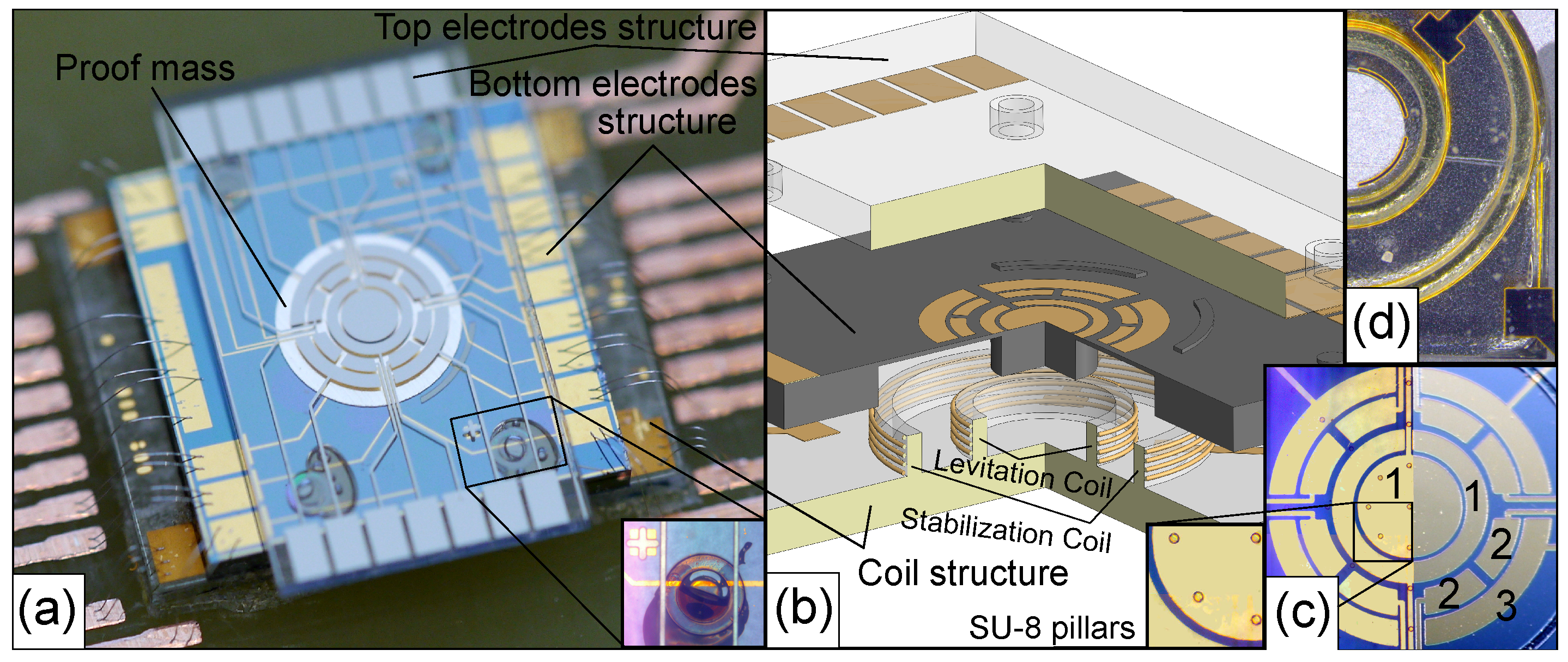
The suspension consists of three structures fabricated independently at the wafer scale, namely a coil structure and the upper and lower electrode structures. These were aligned and assembled into a sandwich by flip-chip bonding into one device with the dimensions: 9.2 × 9.2 × 1.74 , as shown in Figure 1. The coil structure consists of two coaxial 3D wire bonded micro-coils similar to those reported in our previous work [11], namely a stabilization and levitation coil, fabricated on a Pyrex substrate using SU-8 2150; see Figure 1b. For this particular device, a height of the coils is 600 , and the number of windings is 20 and 12 for the levitation and stabilization coil, respectively, which allow us to stably levitate an aluminum disk-shaped proof mass with a diameter of 3.2 and thickness of 30 at a levitation height of 150 . The bottom electrode structure was fabricated on an SOI wafer having a device layer of 40 , a buried oxide of 2 and a handling layer of 600 . The resistivity of the silicon layer is in the range of 1 to 30 . Furthermore, the device layer has a 500 oxide layer for passivation, on top of which electrodes are patterned by UV lithography of evaporated Cr/Au layers (20/150 ), as shown in the left part of Figure 1c. The SU-8 pillars cover the electrodes in order to insulate the proof mass and electrodes and reduce the contact area between the proof mass and the surface, where the proof mass is initially lying flat. The scaled up image at the left of Figure 1c shows the SU-8 pillar having a diameter of 50 and a height of 10 . After etching the handle layer up to the buried oxide by DRIE, the bottom electrode structure was aligned and bonded onto the coil structure, as shown in Figure 1d.
The top electrode structure was fabricated on a Pyrex substrate. The electrodes patterned by UV lithography of evaporated Cr/Au layers (20/150 nm) as shown in the right part of Figure 1c have the same design as those on the bottom structure. To create a gap between the top and bottom structures, four SU-8 posts of 130 in height were fabricated on the top electrode structure. Then, the top structure was aligned and bonded to the bottom one, as shown in Figure 1a.
In order to avoid using an SOI wafer, and thus also to decrease the amount of parallel capacitance arising in the patterned electrodes due to the conductivity of Si, an alternative fabrication route for the bottom electrode structure was explored based on an intrinsically-doped Si wafer of 500 in thickness with a 1- oxide layer for passivation, as shown in Figure 2. On one side of the Si wafer, an SU-8 layer of 30 to 40 in thickness was fabricated by using the epoxy resist SU-8 3025. Then, the electrodes were patterned on this SU-8 layer by UV lithography as shown in Figure 2a. Instead of evaporation, the seed layers Cr/Au (20/150 nm) were sputtered on top of the SU-8 layer. Finally, etching the Si wafer through to the SU-8 layer by DRIE, a cavity for the micro-coils was fabricated as shown in Figure 2b.
2.2. Operating Principle
The proof mass is levitated between the electrode structures. A potential U is applied to the top and bottom electrodes (denoted by the number “1”) and generates an electrostatic field (see Figure 1c), which causes a decrease of stiffness [30]. The series of electrodes numbered “2” are patterned to realize a differential capacitance for sensing the linear displacement of the proof mass along the vertical axis. Electrodes numbered with “3” generate the electrostatic feedback-force needed to operate in a force-rebalance mode. Thus, the prototype can be considered as a levitated micro-accelerometer operating in the vertical direction and providing an adjustable positional stiffness within closed-loop control.
2.3. Preliminary Experimental Results
In order to provide a proof-of-concept and to demonstrate the successful levitation of the proof mass within the electrostatic field generated by electrodes “1”, a preliminary experimental study has been performed (see Figure 3).
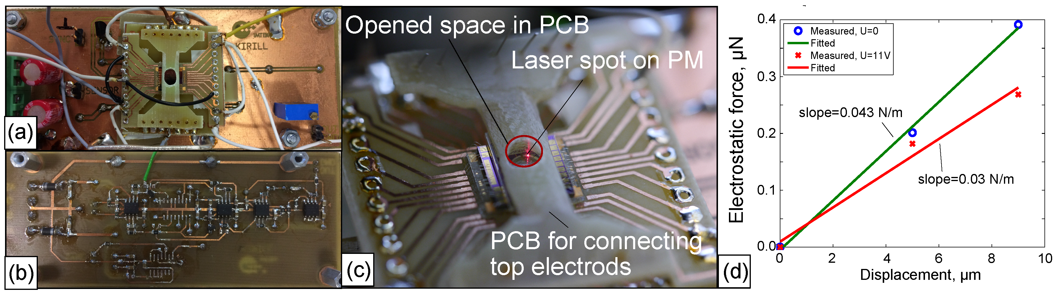
To measure the vertical displacement of the proof mass, a circuit for signal processing and conditioning was developed and fabricated. Using the four pairs of electrodes labeled “2” (see Figure 1c), the capacitive sensing for the vertical displacement of the proof mass, based on a capacitance half-bridge and synchronous amplitude demodulation, was implemented. Each electrode of the pairs “2” was excited by an AC voltage having an amplitude of 3 at a frequency of 100 . After traversing a charge amplifier based on OPA2107AU, the output signal was demodulated by applying a synchronous AM signal. Using switches (ADG441) controlled by a comparator (AD8561), which in turn is synchronized with the excitation voltage and an amplifier (OPA2107AU), a mixer was traversed by the signal. The output from the mixer, passing through an instrumentation amplifier, yielded a differential signal and provided information about the linear displacement.
Coils were fed with a square wave AC current provided by a current amplifier (LCF A093R). The amplitude and frequency of the current in the coils was controlled by a function generator (Arbstudio 1104D) via a computer. A PCB for connecting the top electrodes was fabricated in such way as to leave clear the front of the levitation chip’s electrodes, so that a laser beam could reach the proof mass without obstruction, as shown in Figure 3c. This provided us with an additional means to control the linear displacement of the levitated proof mass using a laser distance sensor (LK-G32 with a resolution of 10 ) and a way to characterize the performance of the capacitive sensing circuit. By applying an electrostatic force generated by the electrodes “3” to the bottom surface of the proof mass, a plot of force against displacement was recorded. From the analysis of the plot, the effective suspension stiffness was estimated.
Assuming that the resulting electrostatic force was applied to the center of the proof mass and accounting for the area of electrode “3” of , the electrostatic force generated by the four electrodes was calculated from , where Fm−1 is the vacuum permittivity, is the relative permittivity (for air ) and h is the space between an electrode’s plane and the equilibrium point of the proof mass.
The results of measurements corresponding to two cases, namely when there is no applied electrical potential to electrodes “1”, and when electrodes “1” are energized, are shown in Figure 3d. First, upon energizing electrodes “1”, the proof mass was stably levitated, and a decrease of the stiffness from 0.043 to 0.03 was observed (also see Table 1). Second, a negative stiffness generated by electrodes “1” can be calculated [37] from , where , to give . This agrees well with the difference of the two measurements. The results are summarized in Table 1.
3. Analytical Model
A schematic diagram for modeling the hybrid contactless suspension is shown in Figure 4a. A typical two-coil stabilization and levitation scheme, arranged to provide stable levitation of a disk-shaped proof mass, is considered. The proof mass is magnetically levitated within the static electric field generated by the top and bottom electrodes. In the general case, it is assumed that the potentials that are applied to the top and bottom electrodes are different and denoted as and , respectively, as shown in Figure 4a. The equilibrium point coincides with the origin O, which lies on the axis of symmetry. The location of the origin is characterized by the following parameters: h is the spacing between the bottom electrode’s plane and the origin, and is the levitation height estimated as the distance between the plane formed by the upper turn of the coils and the origin.
The behavior of an inductively-levitated disk-shaped proof mass (proof mass) within the static electric field generated by the system of electrodes is strongly non-linear, described by the set of Maxwell equations. However, taking into account the fact that the induced eddy current density within the proof mass is distributed continuously, but not homogeneously, two circuits having maximum values of eddy current density can be identified as the representative circuit for the induced eddy current pattern. Furthermore, assuming quasi-static behavior of the levitated proof mass, a simplification in the mathematical description of the hybrid suspension can be obtained. Applying the qualitative technique proposed in [36], an analytical model of the suspension is formulated. Since the design of the suspension is axially symmetric [36], the mechanical part can be represented by the three generalized coordinates , namely , and representing vertical, lateral and angular displacements of the levitated disc, respectively, as introduced in Figure 4b. Considering the capacitors as planar and accounting for , the set describing the motion of the hybrid suspended proof mass becomes
where m is the mass, J is the moment of inertia about the axis perpendicular to the disk plane and passing through the center of mass, , and are the damping coefficients corresponding to the appropriate generalized coordinates, g is the gravity acceleration, , and are the generalized forces and torque corresponding to the appropriate generalized coordinates, and are energies stored in the magnetic and electric fields, respectively, is the dissipation function of the system and and are the charges on the top and bottom electrodes, respectively. Note that magnetic and electric energies stored in the systems can be described in a way similar to those reported in [30,36].
A necessary, but not sufficient condition for stable levitation of the proof mass, near its equilibrium point, is that the second derivatives of electromagnetic energy stored in the system, defined by the following constants , where and , must correspond to a positive definite quadratic form [38]. Note that the necessary and sufficient conditions for stable levitation in micro-machined inductive suspensions require, in addition, taking into accounting the nonconservative positional force due to the resistivity of the proof mass and the dissipative force acting on the levitated proof mass [36]. Thus, the nonlinear set of Equation (1) forms a generalized analytical model of the hybrid contactless suspension and provides opportunities for modeling its dynamics and stability.
The Accelerometer Equation of Motion
In the framework of the proposed application of the device as an accelerometer, as considered in Section 2.2, the behavior of the proof mass along the vertical direction in the hybrid contactless suspension is of special interest and studied in detail below. The static and dynamic responses of the device along this direction are therefore investigated.
Neglecting the generalized coordinates and and also assuming that the resistivity of the conducting proof mass and its linear and angular velocities is small, no damping exists and , then the exact quasi-static nonlinear model, which describes the behavior of the proof mass along the vertical axis, is [30,39]:
where I is the amplitude of a harmonic current i in the coils, L is the self-inductance of the proof mass, M is the mutual inductance between the proof mass and coils and U is the applied voltage to the electrodes. Each electrode set has the same area of , , where is the permeability of free space.
In the general case, the mutual inductance M is a complex non-analytical function. This represents the main difficulty for the analytical study of the suspension model (2). However, we can account for some particularities of the micro-machined device, in that the linear sizes of the coils and proof mass are much larger than the levitation height, , and the distribution of the density of the induced eddy current is not homogenous. The induced eddy current is distributed along the levitated proof mass in such a way that two circuits corresponding to maximum values of the eddy current density can be identified, as shown in Figure 4a. The eddy current circuit is defined geometrically as a circle having the same diameter as the proof mass. The second circuit is also a circle, but with the diameter of the levitation coil [36]. Actually, the second circuit can be considered as the current image of the levitation coil. Due to the mentioned particularities of the device, the force interaction along the vertical direction is reduced to an interaction between eddy current and the levitation coil current [40]. Considering both the levitation coil and the eddy current circuit as filamentary circles, the mutual inductance between the levitation coil and eddy current can be described by the Maxwell formula ([41], page 6); thus:
where is the magnetic permeability of free space, is the radius of the levitation coil and K and E are complete elliptic integrals of the first and second kinds [42]. Then, accounting for (3), Model (2) becomes:
where and . Model (4) is analytical, nonlinear and quasi-exact, but due to the elliptic integrals, it can be studied only numerically. For further analysis, Model (4) is presented in dimensionless form as follows:
here , , , , and .
Moreover, upon ensuring a condition described further below, Equation (3) can be approximated well by the logarithmic function [34]:
Hence, accounting for the latter equation, the following reduced analytical model of a suspension is proposed:
In dimensionless form, Equation (7) becomes:
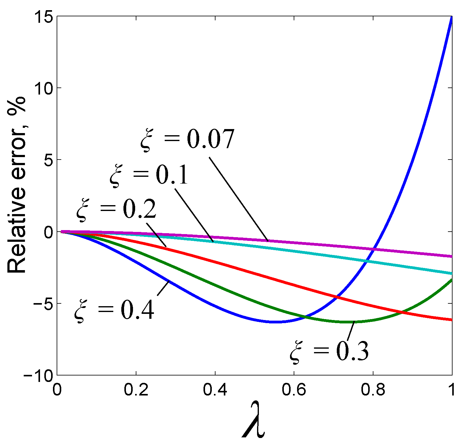
As is shown in Appendix A below, the accuracy of approximation of modeling the electromagnetic force is dependent on the parameter . If is less than 0.3, the electromagnetic force is approximated by the logarithmic function (6) with an error less than 6%. When parameter vanishes, the error between the exact Equation (3) and the approximation (6) also vanishes. It is worth noting that, for all known prototypes of -HCS published in the literature, parameter is less than 0.25. This fact indicates the applicability of the reduced model for further analytical study of -HCS, as has already been successfully demonstrated for instance in [32]. Hence, Model (8) is the main framework for further analysis of the static and dynamic pull-in.
4. Static Pull-In Instability
We now study the load-free behavior of the device upon changing the strength of the electric field, characterized by the dimensionless parameter (dimensionless squared voltage). For this reason, Equation (8) is written as a set in terms of the phase coordinates [31]:
From (9), the equilibrium state of the system can be defined as:
where is the design parameter depending on . At the equilibrium point , the function f must equal zero; this point requires that parameter . Hence, the static equilibrium state of the system, which relates the vertical coordinate with the strength of the electric field, is:
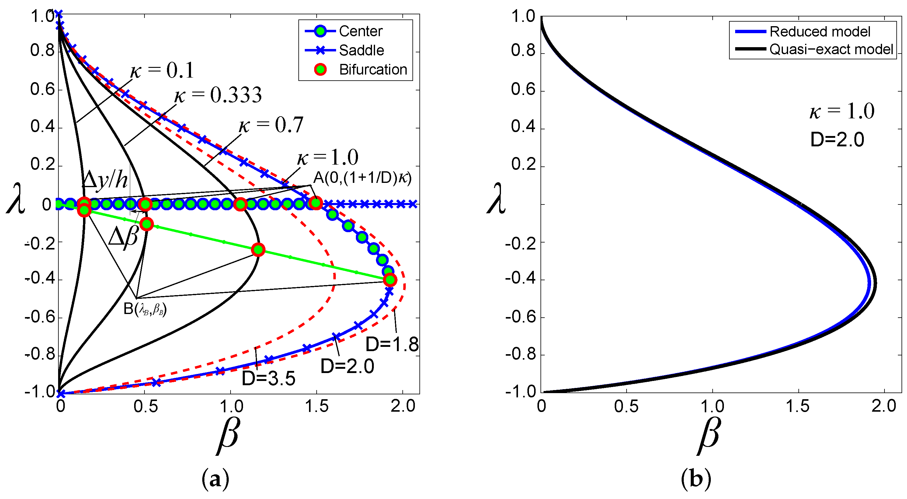
Since the vertical displacement of the proof mass is limited by the positions of the top and bottom electrodes, the variable is varied within a range of . Furthermore, taking into account that constant D and can be considered within the following ranges of and , the bifurcation diagram, which relates the distribution of saddles (unstable equilibrium), centers (stable equilibrium) and bifurcations with the dimensionless square voltage is shown in Figure 5a. Note that the presented prototype of the hybrid suspension in Section 2 has the following values of dimensionless parameters, namely , and . Analysis of the diagram shows that two bifurcation points can be recognized, denoted as A and B. Both bifurcation points correspond to the pull-in instability. This means that, once the strength of the electric field has achieved the value characterized by , the proof mass is pulled in and moves toward the top electrodes. At point B, where the strength of the electric field is characterized by , the proof mass at the position characterized by is also pulled in, but moves already toward the bottom electrodes.
The bifurcation point A is defined by the following parameters:
Parameters and characterizing bifurcation point B (static pull-in instability) are defined numerically as the solution of the following set of equations:
when is small, then the set (13) has an approximate solution:
In addition, a comparison between reduced Model (8) and the quasi-exact model (5) is performed for the considered design of the hybrid suspension in this work, characterized by the following dimensionless parameters and . The result of this comparison is presented in Figure 5b. Analysis of Figure 5b reveals that the relative error is not in excess of 2%.
The ranges of parameters , and and establish a stable state of equilibrium (see Figure 5a). A region near the bifurcation point A is of special interest, because it defines a state of zero stiffness of the suspension. As seen, a decrease of stiffness leads to decreasing a range of linear displacement of the proof mass. Near bifurcation point A, the range of displacement becomes:
Using Equation (15), the minimum possible value of linear stiffness still capable of upholding stable levitation can be estimated. For instance, in the fabricated design of the suspension (see Table 1), upon controlling the linear displacement of the proof mass within a range of , the relative minimization of the stiffness can be expected to be around 0.007. This means that the initial stiffness generated by the inductive suspension can be reduced by two orders of magnitude. Note that the design of the suspension corresponds to a bifurcation curve with , as shown in Figure 5a.
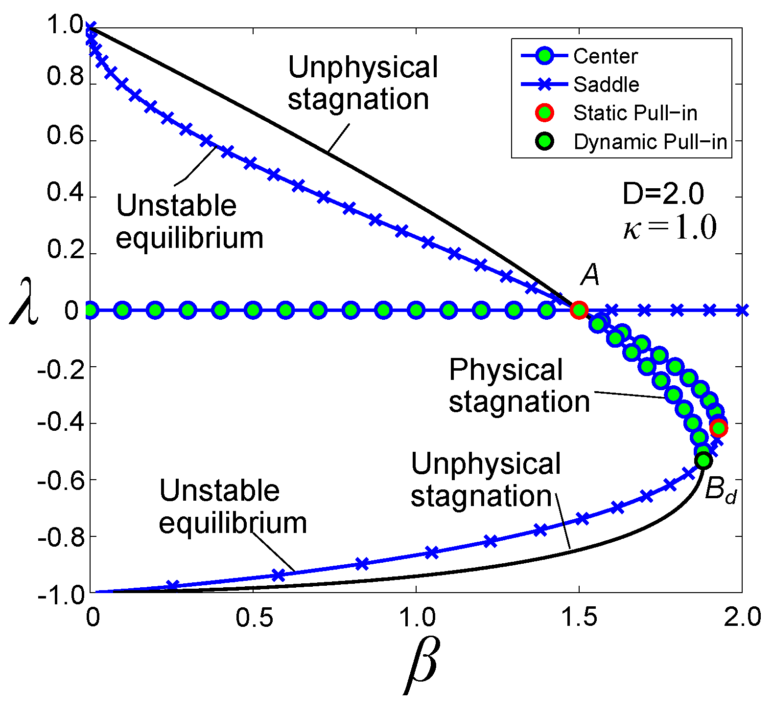
5. Dynamic Pull-In Instability
An equation for the integral curves of set (9) can be obtained as follows:
Integrating (16), the equation of energy is obtained as:
where G is an arbitrary constant of the integration. From the analysis of (17), it is very important to note the following observation, that in order to operate the device properly, it is required to remove the energy of the electric field characterized by parameter from the system, in order to satisfy the initial conditions. Since G is an arbitrary constant, it can be chosen to be equal to . Then, the final form of the integral equation becomes:
From (18), the dynamic equilibrium state can be written as:
Using (19), the bifurcation diagram can be plotted as shown in Figure 6. Similar to the static bifurcation diagram, it has two pull-in instability points (see Figure 6). One point has the same coordinates as point A shown in (12) corresponding to the static pull-in instability, but has different coordinates compared to the static pull-in point B and can be found by numerically solving the following set:
Similar to Section 4, we consider the case when is small, then the set (20) has an approximate solution:
Note that, when the spacing tends to zero, the static and dynamic pull-in displacements tend to their zero initial position, and pull-in voltages also tend to zero. Once , all static and dynamic pull-in points merge into one zero point.
6. Conclusions
In this article, a micro-machined hybrid suspension based on combining electromagnetic inductive and electrostatic actuation, which provides, in particular, control over and decrease of the vertical component of stiffness, was presented. We discussed the micromachined fabrication process of the device establishing three micro-structures, namely coil, top electrode and bottom electrode structure. In particular, two possible ways of fabrication of the bottom electrode structures based on SOI and Si wafer were considered. Using the developed micro-machined process, a prototype of the suspension was successfully fabricated. The preliminary experimental study of this prototype was performed and successfully demonstrated the proof of concept of the device proposed in [30]. In particular, the disk-shaped aluminum proof mass was levitated between the top and bottom structures generating the electrostatic field. A decrease of the vertical component of the stiffness by 25% was successfully observed.
A generalized analytical model of the suspension was also developed. In order to study the behavior of the hybrid suspension along the vertical direction as a particular case of the developed model, a quasi-exact nonlinear model was formulated. Then, using the design particularities of a micro-machined version of the suspension, a reduced model was proposed. It is worth noting that the applicability of the analytical technique used for modeling a hybrid suspension has been already successfully demonstrated for instance in [32]. Using the reduced nonlinear model, the static and dynamic responses of the suspension were analytically and comprehensively investigated, and the static and dynamic pull-in parameters were identified. In particular, it was shown that within the framework of the developed prototype, the initial stiffness generated by the inductive suspension could be reduced by two orders of magnitude.
Acknowledgments
K.P. acknowledges with thanks the support of the Alexander von Humboldt Foundation of his research project performed at the University of Freiburg. He deeply thanks U. Wallrabe for perfectly hosting and supporting his Humboldt project. K.P. also acknowledges with thanks the support from the German Research Foundation (DFG Grant KO 1883/26-1).
Author Contributions
Kirill V. Poletkin developed and fabricated the device, performed the experiment, developed and studied the models and wrote the manuscript. Jan G. Korvink analyzed intensively the developed model and the obtained experimental results and also contributed in improvement of the writing of the manuscript.
Conflicts of Interest
The authors declare no conflict of interest.
Abbreviations
The following abbreviations are used in this manuscript:
| Amplitude modulator | |
| Deep reactive-ion etching | |
| Negative stiffness | |
| Silicon-on-Insulator | |
| -CS | Micro-machined Contactless Suspensions |
| -ECS | Micro-machined Electrostatic Suspensions |
| -MCS | Micro-machined Magnetic Suspensions |
| -HCS | Micro-machined Hybrid Suspensions |
Appendix A
The accuracy of approximation of modeling the electromagnetic force by means of the reduced model (8) depending on the parameter , as shown in Figure A1. Analysis of Figure A1 shows that, if the parameter is less than 0.3, the electromagnetic force is approximated by the logarithmic function (6) with an error less than 6%.

References
- Post, E.R.; Popescu, G.A.; Gershenfeld, N. Inertial measurement with trapped particles: A microdynamical system. Appl. Phys. Lett. 2010, 96, 143501. [Google Scholar] [CrossRef]
- Poletkin, K.V. Thermal Noise in Ideal Micro-machined Levitated Gyroscope. In Proceedings of the MikroSystemTechnik Congress 2017, Munich, Germany, 23–25 October 2017; VDE Verlag: München, Germany, 2017; pp. 789–792. [Google Scholar]
- Poletkin, K.V.; Korvink, J.G.; Badilita, V. Mechanical Thermal Noise in Micro-Machined Levitated Two-Axis Rate Gyroscopes. IEEE Sens. J. 2018, 18, 1390–1402. [Google Scholar] [CrossRef]
- Poletkin, K.V.; Badilita, V.; Lu, Z.; Wallrabe, U.; Shearwood, C. Magnetic Sensors and Devices: Technologies and Applications; CRC Press: Boca Raton, FL, USA, 2017; pp. 101–131. [Google Scholar]
- Toda, R.; Takeda, N.; Murakoshi, T.; Nakamura, S.; Esashi, M. Electrostatically levitated spherical 3-axis accelerometer. Technical Digest. In Proceedings of the Fifteenth IEEE International Conference on Micro Electro Mechanical Systems (Cat. No. 02CH37266), Las Vegas, NV, USA, 24 January 2002; pp. 710–713. [Google Scholar]
- Murakoshi, T.; Endo, Y.; Fukatsu, K.; Nakamura, S.; Esashi, M. Electrostatically levitated ring-shaped rotational gyro/accelerometer. Jpn. J. Appl. Phys. 2003, 42, 2468–2472. [Google Scholar] [CrossRef]
- Cui, F.; Liu, W.; Chen, W.; Zhang, W.; Wu, X. Design, Fabrication and Levitation Experiments of a Micromachined Electrostatically Suspended Six-Axis Accelerometer. Sensors 2011, 11, 11206–11234. [Google Scholar] [CrossRef] [PubMed]
- Han, F.; Liu, Y.; Wang, L.; Ma, G. Micromachined electrostatically suspended gyroscope with a spinning ring-shaped rotor. J. Micromech. Microeng. 2012, 22, 105032. [Google Scholar] [CrossRef]
- Han, F.; Sun, B.; Li, L.; Wu, Q. Performance of a sensitive micromachined accelerometer with an electrostatically suspended proof mass. IEEE Sens. J. 2015, 15, 209–217. [Google Scholar]
- Coombs, T.; Samad, I.; Ruiz-Alonso, D.; Tadinada, K. Superconducting micro-bearings. IEEE Trans. Appl. Supercond. 2005, 15, 2312–2315. [Google Scholar] [CrossRef]
- Lu, Z.; Poletkin, K.; Hartogh, B.d.; Wallrabe, U.; Badilita, V. 3D micro-machined inductive contactless suspension: Testing and Modeling. Sens. Actuators A Phys. 2014, 220, 134–143. [Google Scholar] [CrossRef]
- Poletkin, K.; Moazenzadeh, A.; Mariappan, S.G.; Lu, Z.; Wallrabe, U.; Korvink, J.G.; Badilita, V. Polymer Magnetic Composite Core Boosts Performance of 3D Micromachined Inductive Contactless Suspension. IEEE Magn. Lett. 2016, 7, 1–3. [Google Scholar] [CrossRef]
- Poletkin, K.V.; Lu, Z.; Maozenzadeh, A.; Mariappan, S.G.; Korvink, J.G.; Wallrabe, U.; Badilita, V. 3D Micro-machined Inductive Suspensions with the Lowest Energy Consumption. In Proceedings of the MikroSystemTechnik Congress 2017, Munich, Germany, 23–25 October 2017; VDE Verlag: München, Germany, 2017; pp. 500–502. [Google Scholar]
- Shearwood, C.; Ho, K.; Williams, C.; Gong, H. Development of a levitated micromotor for application as a gyroscope. Sens. Actuators A Phys. 2000, 83, 85–92. [Google Scholar] [CrossRef]
- Su, Y.; Xiao, Z.; Ye, Z.; Takahata, K. Micromachined Graphite Rotor Based on Diamagnetic Levitation. IEEE Electron Device Lett. 2015, 36, 393–395. [Google Scholar] [CrossRef]
- Su, Y.; Zhang, K.; Ye, Z.; Xiao, Z.; Takahata, K. Exploration of micro-diamagnetic levitation rotor. Jpn. J. Appl. Phys. 2017, 56, 126702. [Google Scholar] [CrossRef]
- Garmire, D.; Choo, H.; Kant, R.; Govindjee, S.; Sequin, C.; Muller, R.; Demmel, J. Diamagnetically levitated MEMS accelerometers. In Proceedings of the International IEEE Solid-State Sensors, Actuators and Microsystems Conference, Lyon, France, 10–14 June 2007; pp. 1203–1206. [Google Scholar]
- Ando, B.; Baglio, S.; Marletta, V.; Valastro, A. A Short-Range Inertial Sensor Exploiting Magnetic Levitation and an Inductive Readout Strategy. IEEE Trans. Instrum. Meas. 2018, PP, 1–8. [Google Scholar] [CrossRef]
- Dieppedale, C.; Desloges, B.; Rostaing, H.; Delamare, J.; Cugat, O.; Meunier-Carus, J. Magnetic bistable micro-actuator with integrated permanent magnets. In Proceedings of the IEEE Sensors, Vienna, Austria, 24–27 October 2004; Volume 1, pp. 493–496. [Google Scholar]
- Boukallel, M.; Piat, E.; Abadie, J. Passive diamagnetic levitation: theoretical foundations and application to the design of a micro-nano force sensor. In Proceedings of the 2003 IEEE/RSJ International Conference on Intelligent Robots and Systems (IROS 2003) (Cat. No.03CH37453), Las Vegas, NV, USA, 27–31 October 2003; Volume 2, pp. 1062–1067. [Google Scholar]
- Abadie, J.; Piat, E.; Oster, S.; Boukallel, M. Modeling and experimentation of a passive low frequency nanoforce sensor based on diamagnetic levitation. Sens. Actuators A Phys. 2012, 173, 227–237. [Google Scholar] [CrossRef] [Green Version]
- Lyuksyutov, I.F.; Naugle, D.G.; Rathnayaka, K.D.D. On-chip manipulation of levitated femtodroplets. Appl. Phys. Lett. 2004, 85, 1817–1819. [Google Scholar] [CrossRef]
- Chetouani, H.; Jeandey, C.; Haguet, V.; Rostaing, H.; Dieppedale, C.; Reyne, G. Diamagnetic Levitation With Permanent Magnets for Contactless Guiding and Trapping of Microdroplets and Particles in Air and Liquids. IEEE Trans. Magn. 2006, 42, 3557–3559. [Google Scholar] [CrossRef]
- Lu, Z.; Chen, P.C.Y.; Lin, W. Force Sensing and Control in Micromanipulation. IEEE Trans. Syst. Man Cyberne. Part C 2006, 36, 713–724. [Google Scholar] [CrossRef]
- Liu, W.; Chen, W.Y.; Zhang, W.P.; Huang, X.G.; Zhang, Z.R. Variable-capacitance micromotor with levitated diamagnetic rotor. Electron. Lett. 2008, 44, 681–683. [Google Scholar] [CrossRef]
- Sari, I.; Kraft, M. A MEMS Linear Accelerator for Levitated Micro-objects. Sens. Actuators A Phys. 2015, 222, 15–23. [Google Scholar] [CrossRef]
- Liu, K.; Zhang, W.; Liu, W.; Chen, W.; Li, K.; Cui, F.; Li, S. An innovative micro-diamagnetic levitation system with coils applied in micro-gyroscope. Microsyst. Technol. 2010, 16, 431–439. [Google Scholar] [CrossRef]
- Xu, Y.; Cui, Q.; Kan, R.; Bleuler, H.; Zhou, J. Realization of a Diamagnetically Levitating Rotor Driven by Electrostatic Field. IEEE/ASME Trans. Mechatron. 2017, 22, 2387–2391. [Google Scholar] [CrossRef]
- Poletkin, K.; Lu, Z.; Wallrabe, U.; Badilita, V. A New Hybrid Micromachined Contactless Suspension With Linear and Angular Positioning and Adjustable Dynamics. J. Microelectromech. Syst. 2015, 24, 1248–1250. [Google Scholar] [CrossRef]
- Poletkin, K.V.; Chernomorsky, A.I.; Shearwood, C. A Proposal for Micromachined Accelerometer, base on a Contactless Suspension with Zero Spring Constant. IEEE Sens. J. 2012, 12, 2407–2413. [Google Scholar] [CrossRef]
- Poletkin, K. A novel hybrid contactless suspension with adjustable spring constant. In Proceedings of the 19th International Conference on Solid-State Sensors, Actuators and Microsystems (TRANSDUCERS), Kaohsiung, Taiwan, 18–22 June 2017; pp. 934–937. [Google Scholar]
- Poletkin, K.; Shalati, R.; Korvink, J.G.; Badilita, V. Pull-in Actuation in Micro-machined Hybrid Contactless Suspension. In Proceedings of the 17th International Conference on Micro and Nanotechnology for Power Generation and Energy Conversion Applications (Power MEMS 2017), Kanazawa, Japan, 14–17 November 2017; pp. 150–153. [Google Scholar]
- Elata, D.; Bamberger, H. On the dynamic pull-in of electrostatic actuators with multiple degrees of freedom and multiple voltage sources. J. Microelectromech. Syst. 2006, 15, 131–140. [Google Scholar] [CrossRef]
- Poletkin, K.; Chernomorsky, A.; Shearwood, C.; Wallrabe, U. A qualitative analysis of designs of micromachined electromagnetic inductive contactless suspension. Int. J. Mech. Sci. 2014, 82, 110–121. [Google Scholar] [CrossRef]
- Poletkin, K.V.; Lu, Z.; Wallrabe, U.; Korvink, J.G.; Badilita, V. A qualitative technique to study stability and dynamics of micro-machined inductive contactless suspensions. In Proceedings of the 19th International Conference on Solid-State Sensors, Actuators and Microsystems (TRANSDUCERS), Kaohsiung, Taiwan, 18–22 June 2017; pp. 528–531. [Google Scholar]
- Poletkin, K.; Lu, Z.; Wallrabe, U.; Korvink, J.G.; Badilita, V. Stable dynamics of micro-machined inductive contactless suspensions. Int. J. Mech. Sci. 2017, 131–132, 753–766. [Google Scholar] [CrossRef]
- Poletkin, K.V.; Chernomorsky, A.I.; Shearwood, C. A Proposal for Micromachined Dynamically Tuned Gyroscope, Based on Contactless Suspension. IEEE Sens. J. 2012, 12, 2164–2171. [Google Scholar] [CrossRef]
- Merkin, D.R. Introduction to the Theory of Stability; Springer Science & Business Media: Berlin, Germany, 2012; Volume 24. [Google Scholar]
- Poletkin, K.; Chernomorsky, A.I.; Shearwood, C.; Wallrabe, U. An analytical model of micromachined electromagnetic inductive contactless suspension. In Proceedings of the ASME 2013 International Mechanical Engineering Congress & Exposition, San Diego, CA, USA, 15–21 November 2013; ASME: San Diego, CA, USA, 2013; p. V010T11A072. [Google Scholar]
- Lu, Z.; Poletkin, K.; Wallrabe, U.; Badilita, V. Performance characterization of micromachined inductive suspensions based on 3D wirebonded microcoils. Micromachines 2014, 5, 1469–1484. [Google Scholar] [CrossRef]
- Rosa, E.; Grover, F. Formulas and tables for the calculation of mutual and self-inductance. J. Wash. Acad. Sci. 1911, 1, 14–16. [Google Scholar] [CrossRef]
- Dwight, H.B. Tables of Integrals and Other Mathematical Data, 4th ed.; The MacMillan Company: New York, NY, USA, 1961. [Google Scholar]
Figure 1.
The hybrid suspension: (a) the prototype glued to a PCB. The scaled up image at the bottom right corner shows the alignment and the SU-8 post for spacing (the top electrode structure is not connected); (b) the exploded view; (c) the electrodes patterned at the bottom (right) and top (left); electrode structures: 1, generating negative stiffness; 2, sensing displacement; 3, feedback electrodes; (d) a view of the aligning electrode and coil structures from the rear (Pyrex glass) of the device.

Figure 2.
The bottom electrode structure fabricated by using a Si wafer with an SU-8 layer of 30 in thickness: (a) the front side of the structure; (b) the rear of the structure.
Figure 2.
The bottom electrode structure fabricated by using a Si wafer with an SU-8 layer of 30 in thickness: (a) the front side of the structure; (b) the rear of the structure.
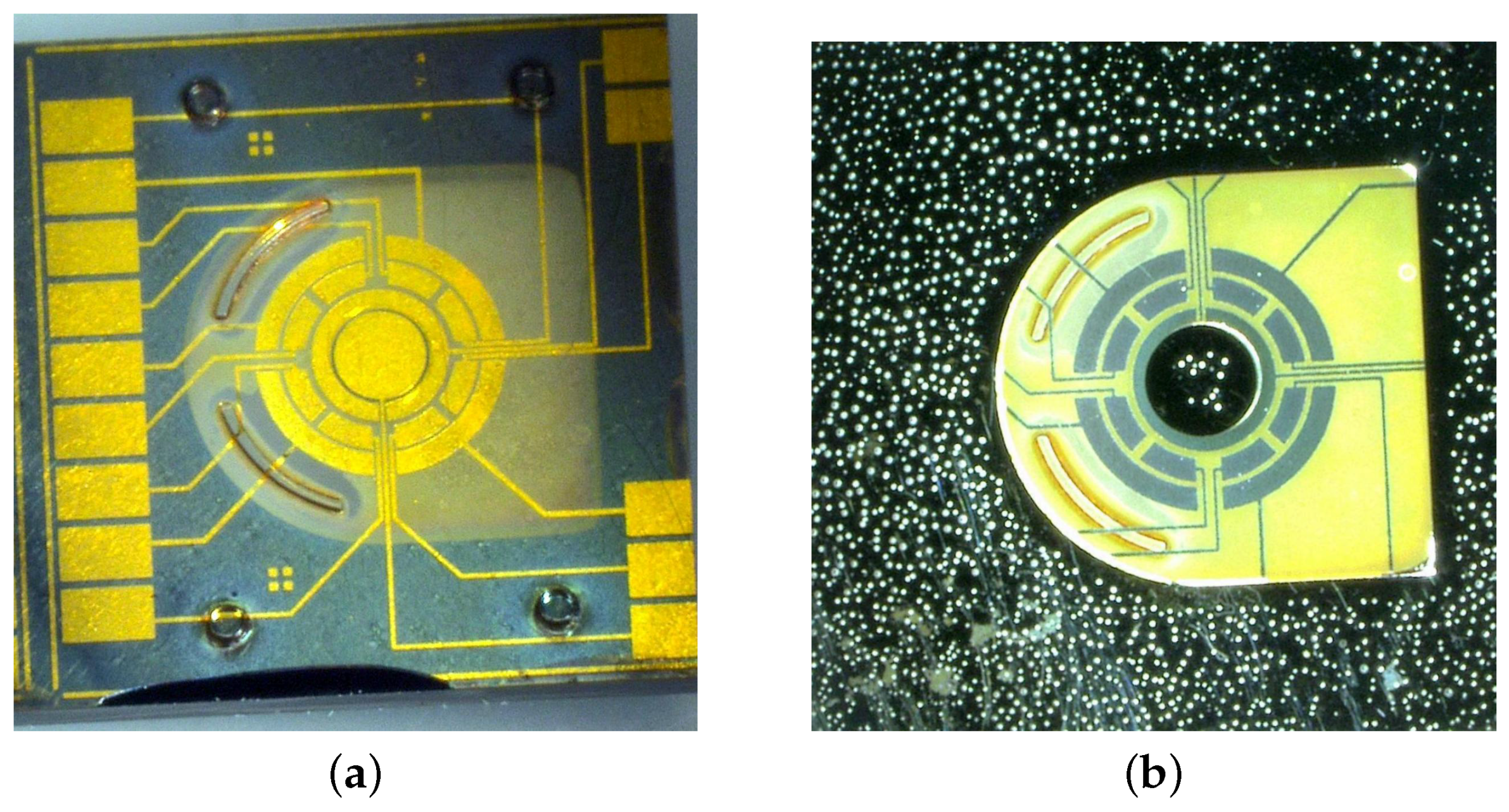
Figure 3.
The prototype under experimental test: (a) the device is fixed on a PCB (front side); (b) the interfacial electronics (rear side); (c) top, bottom and coil structures are connected to the PCB (scaled image); (d) measurements of force against displacement.
Figure 3.
The prototype under experimental test: (a) the device is fixed on a PCB (front side); (b) the interfacial electronics (rear side); (c) top, bottom and coil structures are connected to the PCB (scaled image); (d) measurements of force against displacement.

Figure 4.
Schematic diagram for modeling the hybrid contactless suspension: (a) and are the potentials applied to the top and bottom electrodes, respectively; h is the space between an electrode’s plane and the equilibrium point of the proof mass; is the levitation height between the plane formed by the upper turn of the coils and the equilibrium point of the proof mass; and are the eddy currents corresponding to the maximum current density; (b) coordinate frames and generalized coordinates to define the position of the disc-shaped proof mass around the origin: , , and are the generalized coordinates corresponding to vertical, lateral and angular displacements, respectively.
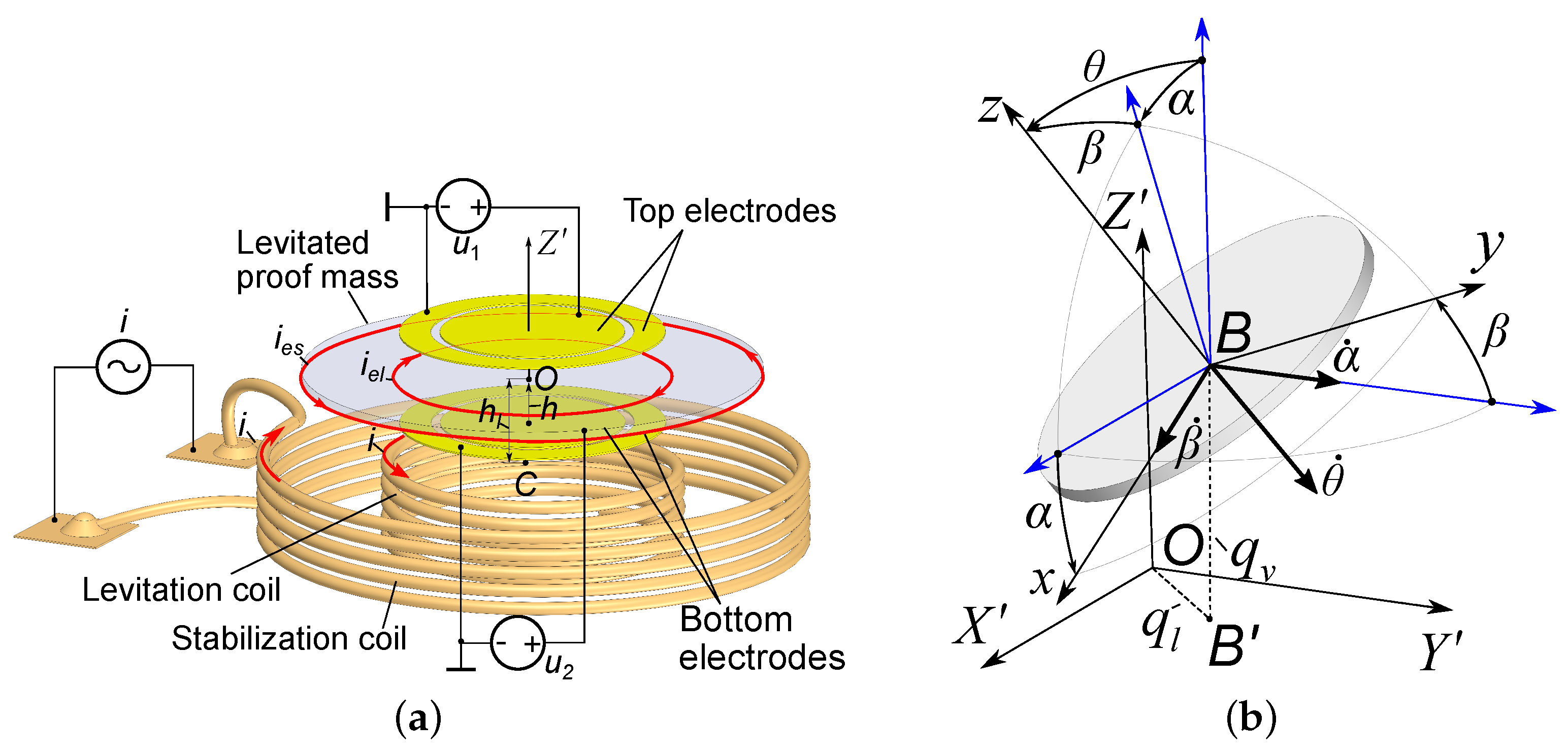
Figure 5.
Bifurcation diagram: (a) dashed red lines show the evolution of the bifurcation map depending on constant D (); solid lines depict the evolution of the bifurcation map depending on spacing (); (b) comparison of the quasi-exact and reduced models for , and (the relative error is less than 2%).

Figure 6.
Static and dynamic bifurcation diagrams: solid black lines correspond to unphysical stagnation.
Figure 6.
Static and dynamic bifurcation diagrams: solid black lines correspond to unphysical stagnation.


Table 1.
Parameters of the prototype and experimental results.
| Parameters of the Prototype | ||
| Diameter of the proof mass | () | 3.2 |
| Thickness of the proof mass | () | 30 |
| Levitation height | () | 150 |
| Spacing | () | 50 |
| Results of Measurements | ||
| Stiffness () | () | 0.043 |
| Stiffness ( V) | () | 0.03 |
© 2018 by the authors. Licensee MDPI, Basel, Switzerland. This article is an open access article distributed under the terms and conditions of the Creative Commons Attribution (CC BY) license (http://creativecommons.org/licenses/by/4.0/).
Share and Cite
MDPI and ACS Style
Poletkin, K.V.; Korvink, J.G. Modeling a Pull-In Instability in Micro-Machined Hybrid Contactless Suspension. Actuators 2018, 7, 11. https://doi.org/10.3390/act7010011
AMA Style
Poletkin KV, Korvink JG. Modeling a Pull-In Instability in Micro-Machined Hybrid Contactless Suspension. Actuators. 2018; 7(1):11. https://doi.org/10.3390/act7010011
Chicago/Turabian StylePoletkin, Kirill V., and Jan G. Korvink. 2018. "Modeling a Pull-In Instability in Micro-Machined Hybrid Contactless Suspension" Actuators 7, no. 1: 11. https://doi.org/10.3390/act7010011
Note that from the first issue of 2016, this journal uses article numbers instead of page numbers. See further details here.