Structural-Parametric Model of Electromagnetoelastic Actuator for Nanomechanics

National Research University of Electronic Technology (MIET), Moscow 124498, Russia
Actuators 2018, 7(1), 6; https://doi.org/10.3390/act7010006
Submission received: 31 October 2017
/
Revised: 4 January 2018
/
Accepted: 11 February 2018
/
Published: 14 February 2018
Abstract
:The generalized parametric structural schematic diagram, the generalized structural-parametric model, and the generalized matrix transfer function of an electromagnetoelastic actuator with output parameters displacements are determined by solving the wave equation with the Laplace transform, using the equation of the electromagnetolasticity in the general form, the boundary conditions on the loaded working surfaces of the actuator, and the strains along the coordinate axes. The parametric structural schematic diagram and the transfer functions of the electromagnetoelastic actuator are obtained for the calculation of the control systems for the nanomechanics. The structural-parametric model of the piezoactuator for the transverse, longitudinal, and shift piezoelectric effects are constructed. The dynamic and static characteristics of the piezoactuator with output parameter displacement are obtained.
1. Introduction
Let us consider the role of an electromagnetoelastic actuator on the piezoeffect, the piezomagnetic effect, and the electrostriction or the magnetostriction effect, which are used for precise alignment in nanomechanics and adaptive optics [1,2,3,4,5,6,7,8]. A piezoactuator uses the inverse piezoeffect and plays a role in the actuation or management of mechanisms, as well as converts electrical signals into the displacement and the force. A piezoactuator is applied for research on the nanomechanics of drives in nanotechnology, microelectronics, adaptive optics, biology as well as in scanning tunnelling microscopes, scanning force microscopes, and atomic force microscopes [7,8,9,10,11,12,13,14,15,16,17,18,19,20,21,22,23,24,25,26,27,28].
In the present paper, the generalized structural-parametric model and the generalized parametric structural schematic diagram of an electromagnetoelastic actuator are constructed by solving the wave equation with the Laplace transform for the equation of the electromagnetolasticity in the general form, the boundary conditions on the loaded working surfaces of the actuator, and the strains along the coordinate axes. The transfer functions and the parametric structural schematic diagrams of the piezoactuator are obtained from the generalized structural-parametric model.
In References [6,7], the solution of the wave equation of the piezoactuator was determined. In References [6,14,15,28], the structural-parametric models and the schematic diagrams for the simplest piezoactuators were obtained, and these were transformed into the structural-parametric model of an electromagnetoelastic actuator with output displacements.
The structural-parametric model of the piezoactuator was determined in contrast to electrical equivalent circuit types Cady and Mason for the calculation of the piezoelectric transmitter and receiver, the vibration actuator, and the vibration motor [8,9,10,11,12,13]. Reference [12] presents the classic analytical two-port lumped-element model (LEM) types Cady and Mason of the piezoelectric composite circular plate with the output pressure. Reference [13] considers the development of various lumped-element models as practical tools to design and manufacture actuators with the output velocity. In References [8,14,15], the transfer functions of the piezoactuator were used to overcome the problem of the absolute stability condition of the strain control system for an electromagnetoelastic actuator.
The elastic compliances and the mechanical and adjusting characteristics of a piezoactuator were explored in Reference [17,18,19] in order to calculate its transfer functions and create the structural-parametric model. The structural-parametric model of a multilayer and compound piezoactuator was determined in References [17,18,19,20,21,22] with output displacement. In this paper, we solve the problem of building the generalized structural parametric model and the generalized parametric structural schematic diagram of an electromagnetoelastic actuator for the equation of electromagnetoelasticity in the general form. The difference of this work from other reports [23,24,26,27,28] is that the construction of the structure-parametric model of the electromagnetoelastic actuator is produced immediately in the general form, and not by the method of mathematical induction from individual examples of models of piezoactuators.
2. Structural-Parametric Model and Transfer Functions of Electromagnetoelastic Actuator
Let us consider the general structural-parametric model and the parametric structural schematic diagram of an electromagnetoelastic actuator with output parameter displacement. For the electromagnetoelastic actuator, six stress components are presented; , , , , , , where the components – are related to extension-compression stresses, and – are related to shear stresses. In the electromagnetoelastic actuator, its deformation corresponds to the stressed state.
For polarized piezoceramics PZT the matrix state equations [11,14] with electric and elastic variables can be given by two equations, where the first equation represents the direct piezoelectric effect, and the second describes the inverse piezoelectric effect:
where is the column matrix of electric induction; is the column matrix of relative deformations; is the column matrix of mechanical stresses; is the column matrix of electric field strength; is the elastic compliance matrix for ; is the matrix of dielectric constants for ; and is the transposed matrix of the piezoelectric modules.
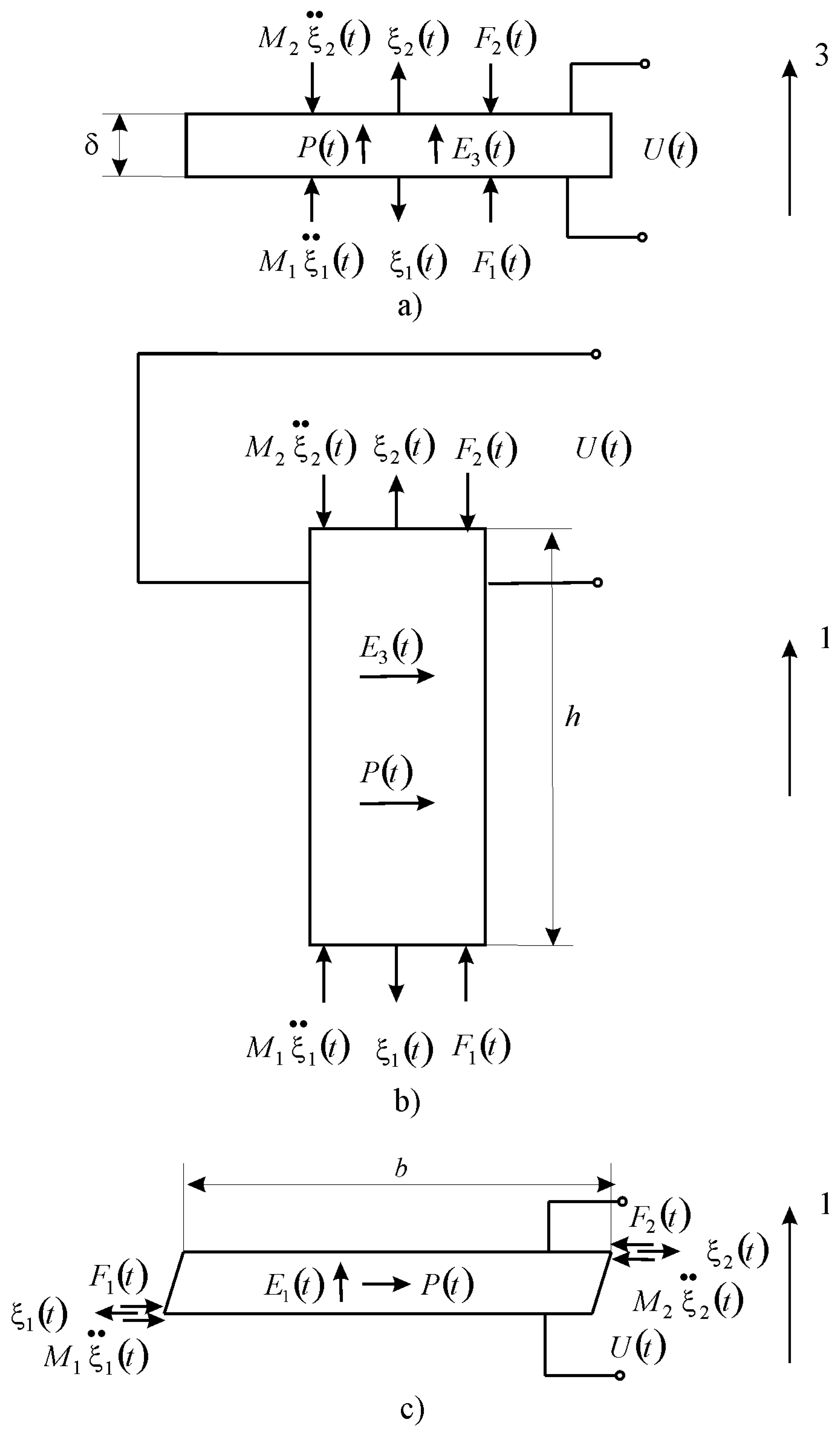
The piezoactuator or piezoplate has the following properties: is the thickness, h is the height, b is the width, and respectively denotes the length of the piezoactuator for the longitudinal, transverse, and shift piezoeffect. The direction of the polarization axis P, i.e., the direction along which polarization was performed, is usually taken as the direction of axis 3 on kinematic schemes of the piezoactuator, shown in Figure 1.
The equation of electromagnetoelasticity [11,14,24] in the general form is:
where , , and is the relative displacement of the cross-section of the piezoactuator along axis i, is the control parameter along axis m = 1, 2, 3 for Figure 1, is the displacement of the section of the piezoactuator, is the piezomodule, is the electric field strength along axis m, is the voltage between the electrodes of the actuator, is the electric induction along axis m, is the magnet field strength along axis m, is the elastic compliance for , is the mechanical stress along axis j, and i, j = 1, 2, …, 6. The main size is the length l of the piezoactuator, respectively, denotes the thickness, height, and width for the longitudinal, transverse, and shift piezoeffect in Figure 1a–c.
To calculate the electromagnetoelastic actuator, we used the wave equation [6,7,14] for the wave propagation in the long line with damping but without distortions. After Laplace transform is obtained, the linear ordinary second-order differential equation with the parameter p is achieved, where the original problem for the partial differential equation of hyperbolic type using the Laplace transform is reduced to the simpler problem for the linear ordinary differential equation.
with its solution
where is the Laplace transform of the displacement of the section of the electromagnetoelastic actuator, is the propagation coefficient, is the sound speed for , is the damping coefficient, and is the control parameter; E stands for the voltage control, D for the current control, and H for the magnet field strength control.
From Equations (3)–(5), the boundary conditions on loaded surfaces, the strains along the axes the system of equations for the generalized structural-parametric model, and the generalized parametric structural schematic diagram are determined in Figure 2 for the electromagnetoelastic actuator with output parameters and the Laplace transform for the displacements of the faces in the form:
where , , , , , , is the coefficient of the electromagnetolasticity or the piezomodule, the coefficient of magnetostriction, and , are the Laplace transform of the forces on the faces of the electromagnetoelastic actuator in Figure 1a–c.
The generalized parametric structural schematic diagram (Figure 2) of the electromagnetoelastic actuator corresponds to Equation (6) for the Laplace transform of the displacements of the faces. The generalized transfer functions of the electromagnetoelastic actuator are the ratio of the Laplace transform of the displacement of the face actuator and the Laplace transform of the corresponding control parameter or the force at zero initial conditions. From Equation (6), the generalized matrix equation of the deformation for the electromagnetoelastic actuator has the form:
where
Let us find the displacement of the faces the electroelastic actuator in the stationary regime for , , and inertial load. The static displacement of the faces of the electroelastic actuator and can be written in the following forms:
where is the mass of the electroelastic actuator, and are the load masses.
The static displacements of the faces of the piezoactuator for the longitudinal piezoeffect (Figure 1a) and and are obtained in the following forms:
Let us consider a numerical example for a piezoactuator from PZT m/V, V, kg, and kg. We obtain the static displacements of the faces of the piezoactuator for the longitudinal piezoeffect: nm, nm, nm.
The static displacements of the faces of the piezoactuator for the transverse piezoeffect (Figure 1b) and and are determined in the following forms:
For the piezoactuator from PZT under the transverse piezoeffect at and , m/V, , V, kg, and kg. The static displacements of the faces are obtained: nm, nm, nm.
From Equation (7), the transfer function of the piezoactuator for the transverse piezoelectric effect for one rigidly fixed face of the piezoactuator at is determined in the form:
From Equation (15), the resonance condition at and is obtained in the form:
where is the frequency coefficient; is the circular frequency.
Because
where index .
Therefore, the piezoactuator is the quarter-wave vibrator with the resonance frequency:
For the piezoactuator from PZT under the transverse piezoeffect at m/s, m, the resonance frequency kHz is obtained. The experimental and calculated values for the piezoactuator are in agreement up to an accuracy of 5%.
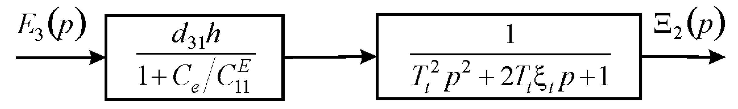
For the approximation of the hyperbolic cotangent by two terms of the power series in transfer function (Equation (15)), the following expressions of the transfer function of the piezoactuator are obtained for the elastic-inertial load at , under the transverse piezoeffect, and the control voltage for the resistance of the voltage source (Figure 3) is given in the form:
where is the Laplace transform of the voltage, is the time constant, and is the damping coefficient of the piezoactuator.
The expression for the transient response of the voltage-controlled piezoactuator for the elastic-inertial load under the transverse piezoeffect and the resistance of the voltage source is determined in the following form:
where is the steady-state value of displacement of the piezoactuator, and is the amplitude of the voltage.
For the voltage-controlled piezoactuator from the piezoceramics PZT under the transverse piezoelectric effect for the elastic-inertial load , and input voltage with amplitude V at m/V, , kg, N/m, H/m, values nm, s are obtained.
3. Results and Discussions
The generalized structural-parametric model, the generalized parametric structural schematic diagram, and the matrix equation of an electromagnetoelastic actuator with output parameters displacements are obtained from the solutions of the wave equation with the Laplace transform and from its deformations along the coordinate axes.
From the generalized matrix equation for the transfer functions of the electromagnetoelastic actuator, the matrix equations of the piezoactuator for the longitudinal, transverse, and shift piezoelectric effects are constructed after algebraic transformations.
The dynamic and static characteristics of the piezoactuator are constructed in order to elucidate the nanomechanics, with regard to its physical parameters and the external load.
The structural-parametric model and the parametric structural schematic diagrams of the voltage-controlled piezoactuator for the longitudinal, transverse, and shift piezoelectric effects are determined from the generalized structural-parametric model of the electromagnetoelastic actuator for the nanomechanics by replacing the generalized parameters with the parameters of the piezoactuator.
4. Conclusions
The generalized structural-parametric model, the generalized parametric structural schematic diagram, and the matrix equation of an electromagnetoelastic actuator with output parameters displacements for the nanomechanics were obtained. The structural-parametric model, the matrix equation for the transfer functions, and the parametric structural schematic diagram of the piezoactuator for the transverse, longitudinal, and shift piezoelectric effects were determined from the generalized structural-parametric model of the electromagnetoelastic actuator.
From the solution of the wave equation with the Laplace transform, the equation of the electromagnetolasticity in the general form, the deformations along the coordinate axes of the generalized structural-parametric model, and the generalized parametric structural schematic diagram of the electromagnetoelastic actuator with output parameters displacements were constructed for the nanomechanics. The deformations of the actuator were described by the matrix equation for the transfer functions of the actuator.
To calculate control systems in the nanomechanics of nanotechnology, microelectronics, nanobiology, astronomy, and adaptive optics, the transfer functions of the electromagnetoelastic actuator were obtained.
The deformations of the piezoactuator for the nanomechanics were described by the matrix equation and the transfer functions of the piezoactuator. The structural-parametric model, the parametric structural schematic diagrams, and the transfer functions of the piezoactuator make it possible to describe the dynamic and static characteristics of the piezoactuator for the nanomechanics with regard to its physical parameters and the external load.
Conflicts of Interest
The authors declare no conflict of interest.
References
- Schultz, J.; Ueda, J.; Asada, H. Cellular Actuators; Butterworth-Heinemann Publisher: Oxford, UK, 2017. [Google Scholar]
- Uchino, K. Piezoelectric Actuator and Ultrasonic Motors; Kluwer Academic Publisher: Boston, MA, USA, 1997. [Google Scholar]
- Przybylski, J. Static and dynamic analysis of a flextensional transducer with an axial piezoelectric actuation. Eng. Struct. 2015, 84, 140–151. [Google Scholar] [CrossRef]
- Ueda, J.; Secord, T.; Asada, H.H. Large effective-strain piezoelectric actuators using nested cellular architecture with exponential strain amplification mechanisms. IEEE/ASME Trans. Mechatron. 2010, 15, 770–782. [Google Scholar] [CrossRef]
- Karpelson, M.; Wei, G.-Y.; Wood, R.J. Driving high voltage piezoelectric actuators in microrobotic applications. Sens. Actuators A 2012, 176, 78–89. [Google Scholar] [CrossRef]
- Afonin, S.M. Solution of the wave equation for the control of an elecromagnetoelastic transduser. Dokl. Math. 2006, 73, 307–313. [Google Scholar] [CrossRef]
- Afonin, S.M. Structural parametric model of a piezoelectric nanodisplacement transduser. Dokl. Phys. 2008, 53, 137–143. [Google Scholar] [CrossRef]
- Afonin, S.M. Stability of strain control systems of nano-and microdisplacement piezotransducers. Mech. Solids 2014, 49, 196–207. [Google Scholar] [CrossRef]
- Talakokula, V.; Bhalla, S.; Ball, R.J.; Bowen, C.R.; Pesce, G.L.; Kurchania, R.; Bhattacharjee, B.; Gupta, A.; Paine, K. Diagnosis of carbonation induced corrosion initiation and progressionin reinforced concrete structures using piezo-impedance transducers. Sens. Actuators A 2016, 242, 79–91. [Google Scholar] [CrossRef] [Green Version]
- Cady, W.G. Piezoelectricity: An Introduction to the Theory and Applications of Electromechancial Phenomena in Crystals; McGraw-Hill Book Company: New York, NY, USA; London, UK, 1946. [Google Scholar]
- Methods and Devices. In Physical Acoustics: Principles and Methods; Mason, W. (Ed.) Academic Press: New York, NY, USA, 1964; Volume 1, p. 515. [Google Scholar]
- Prasad, S.; Gallas, Q.; Horowitz, S.; Homeijer, B. Analytical electroacoustic model of a piezoelectric composite circular plate. AIAA J. 2006, 41, 2311–2318. [Google Scholar] [CrossRef]
- Chiatto, M.; Capuano, F.; Coppola, G.; de Luca, L. LEM characterization of synthetic jet actuators driven by piezoelectric element: A Review. Sensors 2017, 17, 1216. [Google Scholar] [CrossRef] [PubMed]
- Afonin, S.M. Structural-parametric model and transfer functions of electroelastic actuator for nano- and microdisplacement. Chapter 9. In Piezoelectrics and Nanomaterials: Fundamentals, Developments and Applications; Parinov, I.A., Ed.; Nova Science: New York, NY, USA, 2015; pp. 225–242. [Google Scholar]
- Afonin, S.M. Absolute stability conditions for a system controlling the deformation of an elecromagnetoelastic transduser. Dokl. Math. 2006, 74, 943–948. [Google Scholar] [CrossRef]
- Afonin, S.M. Structural-parametric models and transfer functions of electromagnetoelastic actuators nano- and microdisplacement for mechatronic systems. Int. J. Theor. Appl. Math. 2016, 2, 52–59. [Google Scholar] [CrossRef]
- Afonin, S.M. Parametric block diagram and transfer functions of a composite piezoelectric transducer. Mech. Solids 2004, 39, 119–127. [Google Scholar]
- Afonin, S.M. Generalized parametric structural model of a compound elecromagnetoelastic transduser. Dokl. Phys. 2005, 50, 77–82. [Google Scholar] [CrossRef]
- Afonin, S.M. Design static and dynamic characteristics of a piezoelectric nanomicrotransducers. Mech. Solids 2010, 45, 123–132. [Google Scholar] [CrossRef]
- Afonin, S.M. Nano- and micro-scale piezomotors. Russ. Eng. Res. 2012, 32, 519–522. [Google Scholar] [CrossRef]
- Afonin, S.M. Block diagrams of a multilayer piezoelectric motor for nano- and microdisplacements based on the transverse piezoeffect. J. Comput. Syst. Sci. Int. 2015, 54, 424–439. [Google Scholar] [CrossRef]
- Afonin, S.M. Elastic compliances and mechanical and adjusting characteristics of composite piezoelectric transducers. Mech. Solids 2007, 42, 43–49. [Google Scholar] [CrossRef]
- Afonin, S.M. Structural-parametric model electromagnetoelastic actuator nanodisplacement for mechatronics. Inter. J. Phys. 2017, 5, 9–15. [Google Scholar] [CrossRef]
- Afonin, S.M. A structural-parametric model of electroelastic actuator for nano- and microdisplacement of mechatronic system. Chapter 8. In Advances in Nanotechnology; Bartul, Z., Trenor, J., Eds.; Nova Science: New York, NY, USA, 2017; Volume 19, pp. 259–284. [Google Scholar]
- Bhushan, B. (Ed.) Springer Handbook of Nanotechnology; Springer: Berlin, Germany; New York, NY, USA, 2004; p. 1222. [Google Scholar]
- Afonin, S.M. Structural-parametric model of piezoactuator nano- and microdisplacement for nanoscience. AASCIT J. Nanosci. 2017, 3, 12–18. [Google Scholar]
- Afonin, S.M. Wave equation and parametric structural schematic diagrams of electromagnetoelastic actuators nano- and microdisplacement. Int. J. Math. Anal. Appl. 2016, 3, 31–38. [Google Scholar]
- Afonin, S.M. Structural-parametric model electromagnetoelastic actuator nano and microdisplacement for precision engineering. Eng. Technol. 2016, 3, 110–119. [Google Scholar]
Figure 1.
Kinematic schemes of the piezoactuator (a) for the longitudinal piezoeffect; (b) transverse piezoeffect; and (c) shift piezoeffect.
Figure 1.
Kinematic schemes of the piezoactuator (a) for the longitudinal piezoeffect; (b) transverse piezoeffect; and (c) shift piezoeffect.

Figure 2.
Generalized parametric structural schematic diagram of the electromagnetoelastic actuator.
Figure 2.
Generalized parametric structural schematic diagram of the electromagnetoelastic actuator.
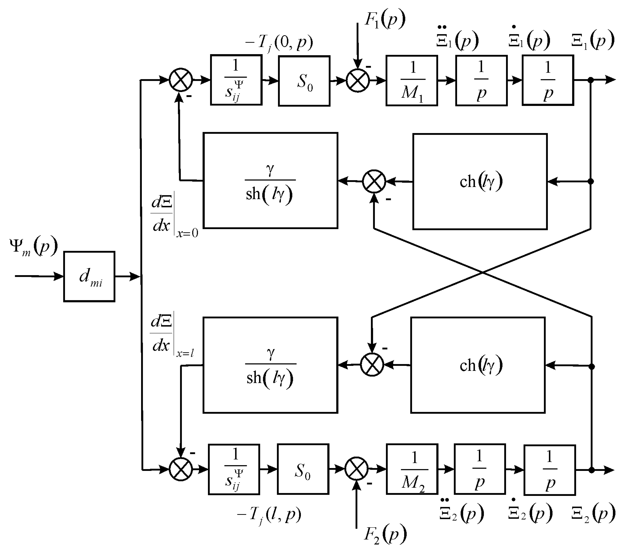
Figure 3.
Parametric structural schematic diagram of the voltage-controlled piezoactuator under the transverse piezoeffect for elastic-inertial load.
Figure 3.
Parametric structural schematic diagram of the voltage-controlled piezoactuator under the transverse piezoeffect for elastic-inertial load.

© 2018 by the author. Licensee MDPI, Basel, Switzerland. This article is an open access article distributed under the terms and conditions of the Creative Commons Attribution (CC BY) license (http://creativecommons.org/licenses/by/4.0/).
Share and Cite
MDPI and ACS Style
Afonin, S.M. Structural-Parametric Model of Electromagnetoelastic Actuator for Nanomechanics. Actuators 2018, 7, 6. https://doi.org/10.3390/act7010006
AMA Style
Afonin SM. Structural-Parametric Model of Electromagnetoelastic Actuator for Nanomechanics. Actuators. 2018; 7(1):6. https://doi.org/10.3390/act7010006
Chicago/Turabian StyleAfonin, S. M. 2018. "Structural-Parametric Model of Electromagnetoelastic Actuator for Nanomechanics" Actuators 7, no. 1: 6. https://doi.org/10.3390/act7010006
Note that from the first issue of 2016, this journal uses article numbers instead of page numbers. See further details here.