Modelling and Control of Ionic Electroactive Polymer Actuators under Varying Humidity Conditions
by

S. Sunjai Nakshatharan
*, 
Veiko Vunder
,
Inga Põldsalu
,
Urmas Johanson
,
Andres Punning
and
Alvo Aabloo
Intelligent Materials and Systems Laboratory, Institute of Technology, University of Tartu, 50411 Tartu, Estonia
*
Author to whom correspondence should be addressed.
Actuators 2018, 7(1), 7; https://doi.org/10.3390/act7010007
Submission received: 29 December 2017
/
Revised: 12 February 2018
/
Accepted: 14 February 2018
/
Published: 20 February 2018
(This article belongs to the Special Issue Electrochemical and Electromechanical Actuators)
Abstract
:In this work, we address the problem of position control of ionic electroactive polymer soft actuators under varying relative humidity conditions. The impact of humidity on the actuation performance of ionic actuators is studied through frequency response and impedance spectroscopy analysis. Considering the uncertain performance of the actuator under varying humidity conditions, an adaptable model using the neural network method is developed. The model uses relative humidity magnitude as one of the model parameters, making it robust to different environmental conditions. Utilizing the model, a closed-loop controller based on the model predictive controller is developed for position control of the actuator. The developed model and controller are experimentally verified and found to be capable of predicting and controlling the actuators with excellent tracking accuracy under relative humidity conditions varying in the range of 10–90%.
1. Introduction
An electroactive polymer (EAP) is a kind of smart material that exhibits a change in shape or size in response to an electric stimulation. Among the different types of EAPs, the ionic electroactive polymers (IEAPs) are highly attractive in the field of sensors and actuators due to their specific characteristics such as their lightweight nature, noiseless operation, and capability of generating large strains at low operating voltages (<3 V). These flexible properties provide superior advantages in using this material for several soft actuator applications. Some of the attempted applications include fish-like robots [1,2,3], grippers [4], microactuators [5], biomedical devices [6], aquatic insectile robots [7], biomimetic robots [8], terrestrial walking robots [9], micro stage platforms [10], etc.
In general, an IEAP is a trilayer structure where a central ion conductive membrane is covered with electronically conductive electrodes on both sides. The most commonly known IEAP is the ionic polymer metal composite (IPMC). It is composed of the ionic polymer membrane, typically Nafion, sandwiched between a pair of noble metal electrodes [1,2,3,4,5]. The whole laminate is contained within an aqueous electrolyte solution. Under an applied electric field, the hydrated cations and water molecules pass through the nanochannels of swollen ionomer and congregate on the surface of the electrode, forming an electrical double layer. The imbalanced distribution of ions leads to a volumetric expansion in one electrode and contraction in the other, causing deformation of the whole film. With a larger electrode surface area, a higher number of ions and water molecules is transported towards the electrodes and hence leads to large deformation. Even though this type of actuator is well studied, a wider deployment of these materials for applications is limited, mainly because of their complex manufacturing, limitation in obtaining large electrode surface area, and unstable operation caused by evaporation and electrolysis of the water, which is typically used as a solvent. These disadvantages of the old type of IPMC and the requirement of the large electrode surface area have led to the development of novel actuators made of porous electrodes and nonvolatile ionic liquid (IL) electrolytes. The use of ionic liquids as electrolytes provides a large electrochemical stability window that allows the actuators to be operated in the open-air environment at a higher electric potential without causing electrolysis and evaporation [11], whereas, the use of porous electrodes makes the fabricating process simple, scalable, and at the same time provides a large surface area contributing to large deformation. The common materials used for fabricating porous electrodes are typically different allotropes of electronically conductive carbon [12,13,14,15].
Although these IL-based IEAPs are capable of operating in an open-air environment, one main disadvantage hindering the use of these actuators for engineering application is their sensitivity towards environmental humidity. The effect of ambient humidity on IEAP actuators and sensors has been widely reported in various studies [12,16,17,18,19]. The main cause for the behavior is attributed to the hydrophilic property of both the ionic liquid and the ionic polymer membrane causing them to absorb water molecules from the surrounding environment.
Effect of Humidity—Overview
The overall influence of the environmental impact on the electrical and mechanical parameters of the IEAP actuators was studied by Vunder et al. by carrying out electromechanical measurements in three different environments: vacuum, dry inert, and ambient air atmosphere [19]. Some major conclusions from the study are listed below.
- The viscosity of IL decreases as it absorbs water molecules from the environment
- The decrease in viscosity is accompanied by an increase in ionic conductivity
- As the relative humidity increases, the double-layer capacitance increases
- The mechanical stiffness of the IL-swollen Nafion decreases with an increase in water absorption
The above factors result in the exhibition of very large strain and a higher speed of response as the environmental humidity increases. The sensitivity of the actuator towards humidity results in unpredictable actuation under different environmental conditions. From a modelling perspective, the model developed under one single humidity will not capture the complete dynamics of the actuator. As a result, the actuator control system may become unstable and fail to control the displacement of the actuator as desired. Applications concerning precise position control in particular may not provide the desired reproducible performance. These factors necessitate the need to study the mechanical characteristics of the actuators in various humidity levels and to develop a model and a control system that could function in the varying conditions.
The main focus of the current work is to develop a modelling scheme and control methodology to handle the effect of humidity on IEAP actuators. To accomplish this, we begin by developing a neural network model of the IEAP actuator, considering the ambient humidity level as one of the input parameters. This approach makes the model adaptable to the varying humidity conditions. The next phase of the work is followed by the development of a closed-loop position control system based on a gain-scheduled model predictive controller. Finally, position-tracking control experiments are conducted at random humidity levels to verify the performance and robustness of the developed model and the controller strategy.
2. Issues with Modelling of the Actuator
Accurate representation of the actuator model allows simulating and evaluating the performance of applications before fabrication and also aids in a better understanding of the actuation mechanisms [5]. So, quite a number of models for ionic polymer transducers are proposed in the literature. Overall, these models can be classified into three major categories, namely physics-based models, black box, and grey box models. Physical models are based on the first principles approach and are typically too complex and consisting of numerous variables. A number of researchers [20,21,22] have developed such models of IEAPs. Chen and Tan [23] suggested a robust H∞ controller for a white box model to achieve a robust response. Although the proposed white box model performed well, it required a number of precise parameters for the actuating system that caused many challenges when using this method [24]. Moreover, there is no reported physical model that takes the humidity effects into account. Grey box models [5,6,19,25] use empirically determined parameters that describe the behavior of the actuator. Usually, the grey box models represent lumped parameter electrical equivalent circuits consisting of resistors and capacitors. These models typically use a strain capacitance coefficient to relate mechanical displacement of the actuator to the charge transferred, which in turn depends on the double layer capacitance [5,22,26]. These models are simple, practical, and less complicated, which makes them desirable for accurate control applications. But under varying environmental conditions, such as humidity, the determined parameters are not constant anymore. The RC parameters undergo a drastic change in response to both the applied input voltage magnitude and the environmental conditions [19]. Hence, any lumped equivalent model representing the actuator at one particular humidity level is no longer valid at other humidities. For that reason, the single equivalent circuit approach, based on linear RC elements, cannot be used to represent the actuator at different environmental conditions.
The black box model is based on identification techniques and does not consider the physical principles. These models are very simple and can be directly applied to control applications. Numerous black box models are proposed [5,27,28,29,30] for force or position control applications of ionic polymer actuators. Adaptive neuro-fuzzy control of ionic polymer metal composites for nonlinear response and back relaxation is presented by Thinh et al. [27]. A comparison of three different neural network models for ionic polymer composite is presented by De Luca et al. [28]. Truong et al. presented a neural network architecture tuned by gradient-descent training [29], but due to the computation complexity of the training, the same authors developed a non-linear black box model based on general multilayer perceptron neural network trained by extended Kalman filter [30]. Kang et al. [31] proposed robust control of IPMC using system identification and compared four different controllers. Similarly, there are other adaptive control methods developed based on the black box model [32,33]. Nevertheless, humidity is not taken into account during control of the actuators.
In this work, the general multilayer neural network model tuned by the Levenberg–Marquardt back-propagation algorithm is used to model the actuator. The distinguishing feature is that the humidity level is also taken into account as a model parameter. This model is then used for prediction and control of the actuator. Since the model is based on system identification using experimental data at different humidity levels, the method is more accurate than all other approaches. Although an accurate model can be obtained using this method, this model is not scalable and transferable to different samples of the same actuator material. One main reason for not being able to develop a scalable model is that there exists a slight difference in the interfacial resistance generated during the manual fabrication procedure. Actuators fabricated within the same batch behave slightly different from one another and so making a scalable model is quite complicated. Nevertheless, this is an attempt to develop a methodology to design a model and control system that takes the humidity effect into consideration. The knowledge gained by this work will enable us to understand the impact of varying environmental conditions on the behavior of the actuators. Moreover, a control strategy has proposed that help to develop future control system architectures and models that are capable of handling the unpredictable environmental impact.
3. Electromechanical Characterization under Varying Humidity
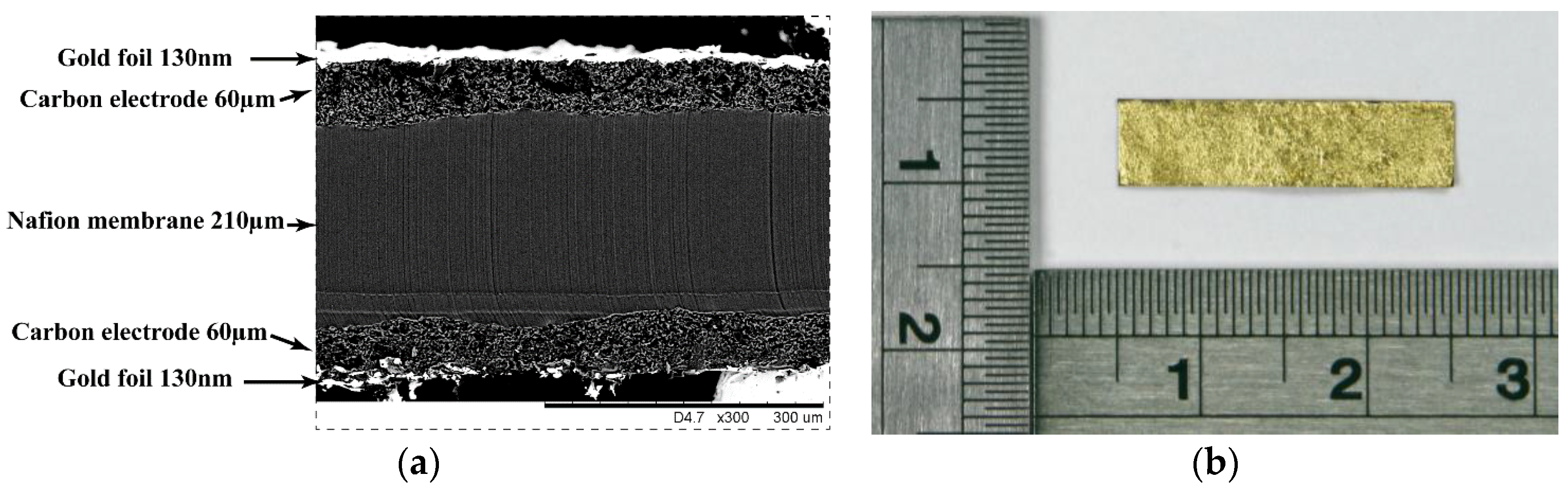
In this work, we study a specific IEAP material that has been extensively characterized [12,19,25]. It is composed of a Nafion® membrane and nanoporous carbide-derived carbon (CDC) electrodes. Compared to carbon nanotubes and graphene, CDC is easier to produce in large quantities and the process of manufacturing the electrodes is easier. For the actuators used in this study, the conductivity of the electrodes is further improved by adding thin gold foils, which are glued to the outer surfaces of the laminate. The ionic liquid electrolyte used is 1-ethyl-3-methylimidazolium trifluoromethanesulfonate (EMIM-Otf). This ionic liquid has an electrochemical stability window of above 3 V which allows the actuator to be operated at higher voltages. The scanning electron microscope (SEM) micrograph of the cross-section of the actuator is shown in Figure 1a and the fabricated actuator under test is shown in Figure 1b. The sample actuator used in the experiment is 20 mm in length, 5 mm wide, and 330 µm thick.
3.1. Actuator Fabrication
A bare Nafion™ 117 membrane was pretreated by roughening both sides with emery paper in order to remove the outer polymer surface layer, which, due to its relatively high hydrophobicity, interacts weakly with the solutions used further on. Roughening also enlarges the polymer–electrode interface area, thereby providing better adhesion. Both sides of the membranes were roughened until the surface appeared to be non-transparent, after which the membranes were washed by boiling in 1 M hydrochloric acid for 30 min, followed by boiling in de-ionized water for 1 h to remove acid residuals. In order to prevent degradation of the ionomer during the relatively long drying procedure at elevated temperature [26], the membranes were ion-exchanged by boiling for 2 h in a 1 M LiClO4 solution. The membranes were then dried in a vacuum at 150 °C for 12 h. Thereafter, the membranes were instantly immersed in ionic liquid (EMIM-Otf) and heated for 5 h at 150 °C. Afterward, the uptake of EMIM-Otf was expected to be near 60% of the dry weight of the membrane. The electrodes were applied to the membrane using the direct assembly process (DAP) [34], i.e., a conductive, nanoporous, carbide-derived carbon powder with the high specific area was mixed with an ionomer solution and painted directly onto the diluent-swollen membrane and sandwiched between two gold foils followed by hot-pressing at 160 °C under 4 MPa for 5–15 s [35].
3.2. Characterization under Different Humidity Levels
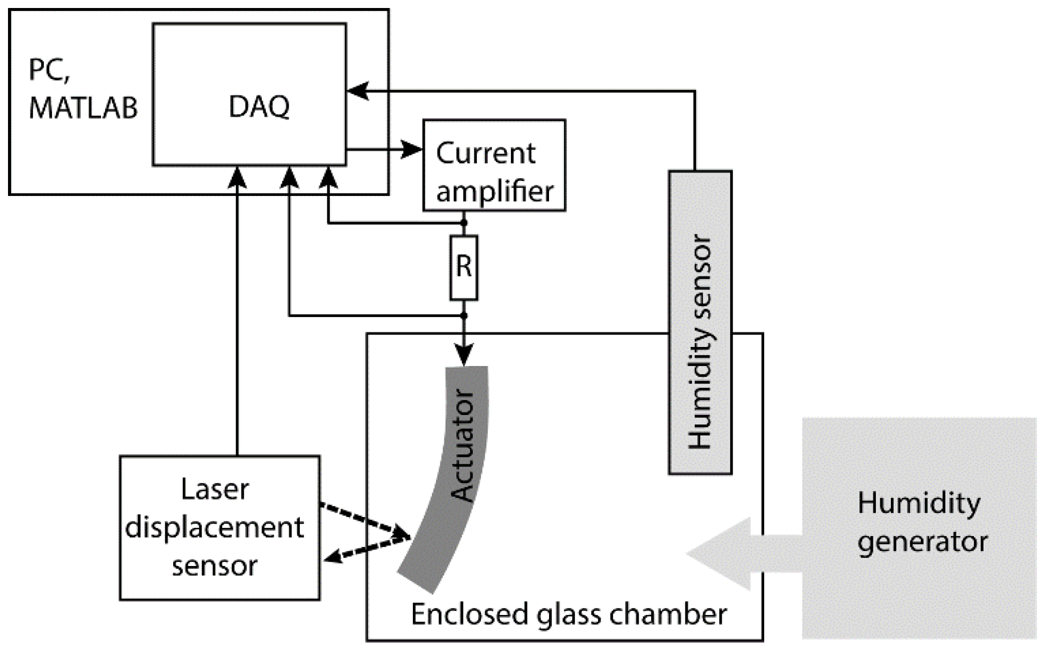
As previously explained, this IEAP actuator is sensitive to ambient humidity. To quantify this effect, the experiments were conducted in a closed glass chamber with the provisions for connecting the actuator, humidity generator, and a humidity sensor as shown in Figure 2.
The actuator tip displacement was measured with a laser displacement sensor (LG10A65PU) and the humidity sensor was kept inside the chamber to measure the chamber’s actual humidity. The actuator, laser displacement sensor, and humidity sensor were connected to a PC running MATLAB via the National Instruments PCI-6221 data acquisition card. The room temperature during the experiments was maintained at 25 °C.
3.3. Experimental Procedure
All characterization and control experimental measurements were carried out in a hermetically closed chamber. The humidity in the chamber was maintained and controlled at a set level by the humidity generator (proUmid MHG32). The equipment was fully capable of maintaining humidity in the range of 5% to 95% automatically. The actuators were fixed in the chamber while the terminals were extended out to make the sealed electrical connections. Before conducting an experiment, the actuators were allowed to get saturated in a specific humidity inside the chamber for about two hours [19]. To measure the response at another humidity level, the humidity within the chamber was varied and the actuators were once again allowed to get saturated for about two hours before conducting the following experiments.
For studying the effect of humidity on deformation of the actuator, mechanical frequency response analysis was performed by exciting it with a sinusoidal signal of magnitude ±2 V in the frequency range from 0.01 Hz to 3 Hz. Figure 3a shows the peak to peak displacement of the actuator for the input signal with a specified frequency at different humidity levels. The results show that at 10% humidity, the peak to peak displacement was about 3.5 mm and at 90% humidity it was 15 mm, showing a variation of nearly 4.5 times, which is highly substantial.
The electrochemical measurement was carried out with the Parstat 2273 of Princeton Applied Research. The impedances of a sample at different humidity levels are depicted in Figure 3b. The corresponding equivalent circuit is shown in Figure 4, where Rs, Rct, W, and Cdl represent the electrolyte resistance, charge transfer resistance, Warburg element, and double layer capacitance, respectively.
Table 1 shows the variation of the parameters with respect to humidity. It shows that the electrolyte resistance decreases as humidity is increased, depicting that the increase in water molecules increases the ionic conductivity and causes the resistance to decrease. In addition, the capacitance is lower at lower humidity and increases as the humidity increases.
These behaviors of the actuator make the task of modelling and designing a controller through a physics-based or equivalent circuit approach to be highly complicated and hence the black box method through the neural network method is adapted and its implementation is described in the following section.
4. Modelling and Control at Different Humidities
As seen from the frequency response analysis, the performance of ionic polymer actuators with IL electrolyte is highly affected by the level of humidity. In order to control such an uncertain system, various control approaches, including adaptive control, intelligent control, and nonlinear control, etc., are possible. In this work, the gain-scheduled method based on Model Predictive Control (MPC) is used. Since MPC has proven to be efficient in different fields, such as chemical engineering, robotics, image processing, and process control [36], it has already become a practice in industrial environments. Also, MPC has the advantage of providing a systematic method of dealing with constraints on inputs and states. The main constraint of the ionic polymer actuators is that to avoid electrolysis, they should be operated at voltages not exceeding the electrochemical stability window of the IL. It is also essential to limit the maximum displacement of the actuator in order to reduce the mechanical damage to the surface, delamination, and aging effects which may happen at large displacements.
4.1. Neural Network Model Predictive Control
At first, the MPC method generally requires a model for optimization, while the model accuracy is essential to provide the desired control performance. In order to model the varying properties of the actuator, the artificial neural networks (ANNs) method is chosen. The neural network method can model a complex nonlinear system, which cannot be easily modeled by other methods [37]. The attractive benefit of the neural network approach is that an accurate representation of the process can be obtained by training the network using samples of input/output data.
4.2. Neural Network Modelling
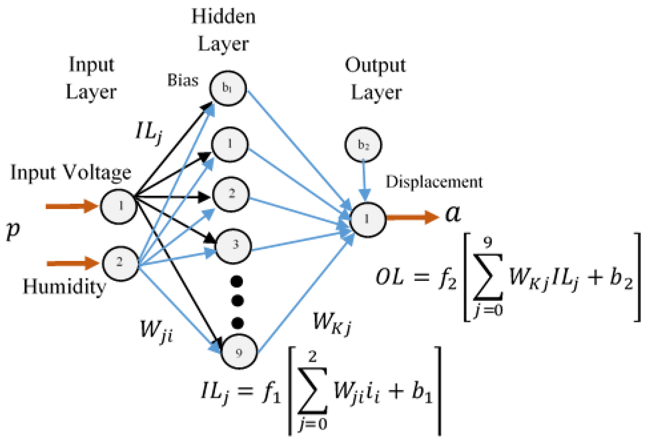
Neural network methods are learning models inspired by the biological neural networks and are used to estimate an approximate function or output that depends on a number of inputs. The networks are generally presented as systems of interconnected neurons, which act as processing elements. A single neuron is a function of input multiplied by a scalar weight to form . This term is then added to a bias . The weight and bias are both scalar parameters and are adjusted by learning rule so that the neuron input/output relationships meet some specified goal. The goal here is to choose the weights and the bias of the network such that the model captures the effects of humidity on the displacement of the actuator. This process of tuning the weights is known as training. The training can be based on experience or based on a standard algorithm and this process makes the neural network adaptive to inputs and capable of learning [38]. The basic schematic of the neural network is shown in Figure 5. In this type of typical multi-neuron network, there are many neurons. Each input to the neuron has its own weight, which forms together a weight matrix .
For this work, a multilayer feedforward network with log sigmoid function for hidden neurons and a linear output function for output neurons are selected. The log sigmoid function squashes the output into a range of 0 to 1 and is commonly used in backpropagation algorithms since the function is differentiable. This structure can also fit multidimensional mapping problems arbitrarily well [39]. The expression of the neural structure is given by following Equation (1)
where is the output, is the input vector, is the input weight matrix, is the bias vector, and is output layer weight matrices, and are transfer function at hidden and output layer which are sigmoidal and linear function, respectively. In the current work, the network is trained with the Levenberg–Marquardt back-propagation algorithm, which has a fast and stable convergence [40].
4.3. Neural Network Training
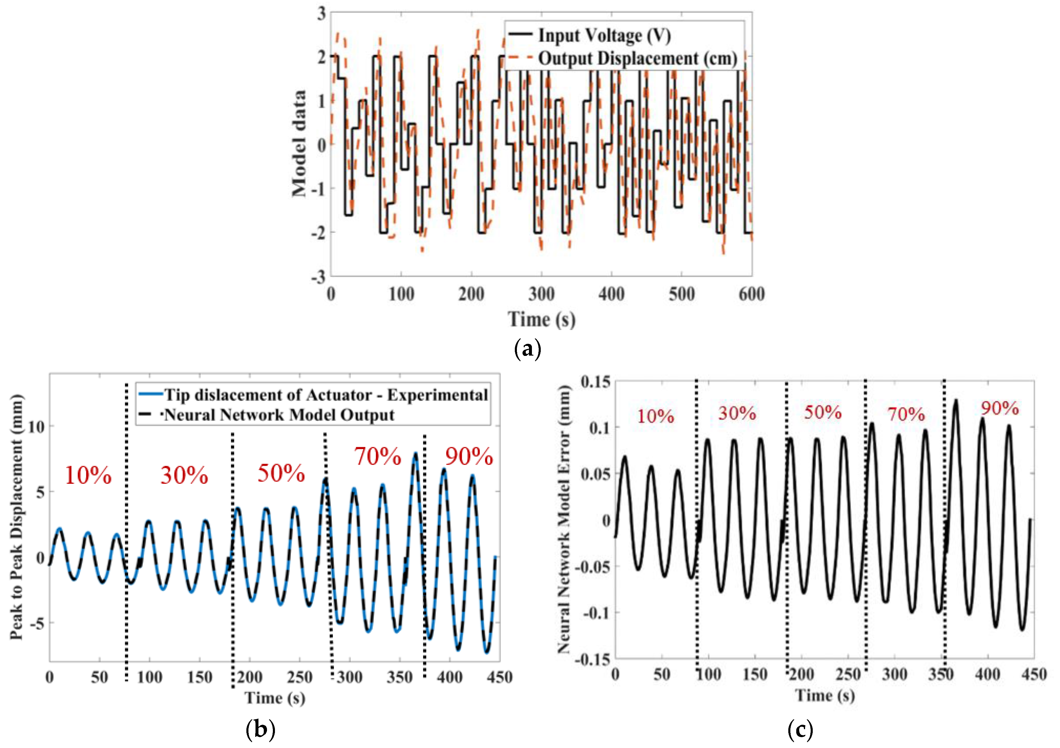
The humidity data from the humidity sensor and the voltage input to the actuator are considered as inputs to the neural network model, and the output to be modeled is the displacement of the actuator. The actuator is kept at a specific humidity for about two hours and then excited with a dynamic input signal while the displacement of the actuator is measured. In order to estimate the system model, the data is divided into two parts, the first part to determine the model, and the second part to validate the model. The neural network training schematic is shown in Figure 6. The sample input excitation signal and the output displacement data collected at 90% humidity used for modelling is shown in Figure 7a.
During training, the number of neurons is increased one by one until the error remains under the pre-specified level. For the current problem, a two-layer network with 9 hidden neurons is selected after repeated training, as it provided the best results. Further addition of neurons does not improve the result but requires more computing power. The comparison of actual displacement and modeled neural network output response for a sinusoidal signal at different humidities is shown in Figure 7b. At all humidity levels, the error between the modeled output and the real-time displacement is limited to 0.1 mm, corresponding to an error of 2%. The error plot is depicted in Figure 7c.
5. Model Predictive Control
Model Predictive Control (MPC) refers to a class of algorithms that computes a sequence of manipulated variable/control signals in order to optimize the future behavior of the process [41]. It is based upon solving an optimization problem for the control actions at each sampling interval. It solves this optimization problem by using the current state of the actuator and the future predicted state from the model to obtain the optimal input vector. It has significant advantages in controlling a Multi-Input-Multi-Output (MIMO) system with a large time delay and constraints [41]. In the MPC scheme, the prediction of a system output over a prediction time horizon NH is considered and the scheme aims to find a sequence of inputs and outputs over the prediction horizon. The cost function or the optimal criteria used in the current model predictive controller is given by the following Equation (2):
where
Here, denotes reference trajectory at instant on the basis of information up to instant (current time), denotes prediction output, is the control signal, and are control weight factors, respectively. Minimizing this objective function by a suitable choice of will provide a trade-off between minimizing the tracking error of the system and increasing the amplitude of the input signal. The constraints which limit the range of the control signal, gradient of the control signal, and the future model predictions are:
where and are minimum and maximum input signals to the actuators, and and are the minimum and maximum output displacements. is the gradient of the control signal between two consecutive sample times.
Here the future outputs from the actuator are given by where is the prediction horizon, up to which the future output displacement is predicted from the model. The future output depends on the actuator’s current states and future control signals. where is the control horizon parameter. The predictive controller computes the potential future control signals such that the future outputs will be as close as possible to the desired position or in other terms, the controller will compute the control signal such that it reduces the error to zero.
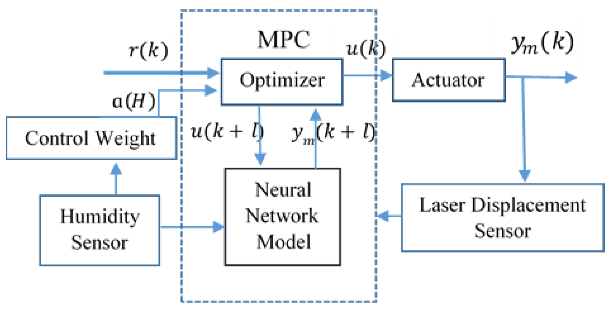
Here the parameter is the weight factor of the control signal and is designed as a function of humidity. This value is used as a tuning parameter to determine the contribution to the performance of the controller. The selection and tuning of the MPC parameters are discussed in the next section. The overall schematics of the working of the controller are depicted in Figure 8. From the scheme, the MPC can be summarized into three major steps. The first step is the prediction step; at each sampling time instant k, with the information from current reference signal , and output displacement , the future behavior of the actuator is predicted over the specified time horizon . In the second step, the objective function is minimized to compute an optimal vector of input signals, up to the control horizon . Then the control signal of the control vector is applied to the actuator. At the next sampling time , the whole process of prediction and optimization will be repeated. During the change in humidity, the neural network model gets adapted and also the control weights of the optimizer and hence the optimal control signal for the specified humidity is computed.
MPC Tuning and Optimization for Operation under Different Humidities.
For successful implementation, MPC parameters need to be tuned. The first parameter to be chosen is the prediction horizon . This is commonly taken as at least 1.2 times the settling time of the system [41] and always . Here, the prediction horizon of 40 steps with 0.1 s sampling time is selected. The control horizon parameter is tuned online for a smooth control performance, whereas only gives marginal performance improvements. The maximum and minimum control input signal is constrained to ; above the range will damage the actuator permanently. The set point or the displacement range is limited to
Here, is the tuning parameter selected to play a role in controlling the actuator at different humidities. Following the gain-scheduled approach for each particular humidity, the different control weights are tuned online. This method of gain-scheduled control for non-linear plants have been proven as a successful design methodology in many engineering applications. The well-known application is the multiple model adaptive control of aircraft [42,43], while another engineering application of process control was presented in [44]. The gain scheduling method was reviewed extensively in the survey paper [45]. The gain-scheduled control system uses linear control strategies to control a nonlinear plant, and the family of closed-loop linear systems is made stable in the vicinity of each linear model [46]. The method has been proven with guaranteed properties on robustness, performance, and nominal stability.
The parameter is tuned for different humidities such as 10%, 20%, 30%, 50%, 70%, and 90%. Under the low humidity range (<30%), the parameter is tuned for short intervals, i.e., for every 10% humidity change, since the experiments have shown that under low humid conditions even a small change in humidity reflects a wide change in the behavior of the actuator. Hence, in order to obtain a robust performance of the controller, the gain has to be scheduled for short intervals of humidity range. Above 30% humidity, the gain is scheduled at an interval of 20% change. Figure 9b shows the relation between humidity and the control weights; a second order polynomial function is derived based on the relation. This control weight as a function of humidity is used for controlling the actuator at humidities ranging from 10% to 90%. Figure 9a below depicts the method of gain scheduling the controller. The control parameters are shown in Table 2.
6. Position Control Results
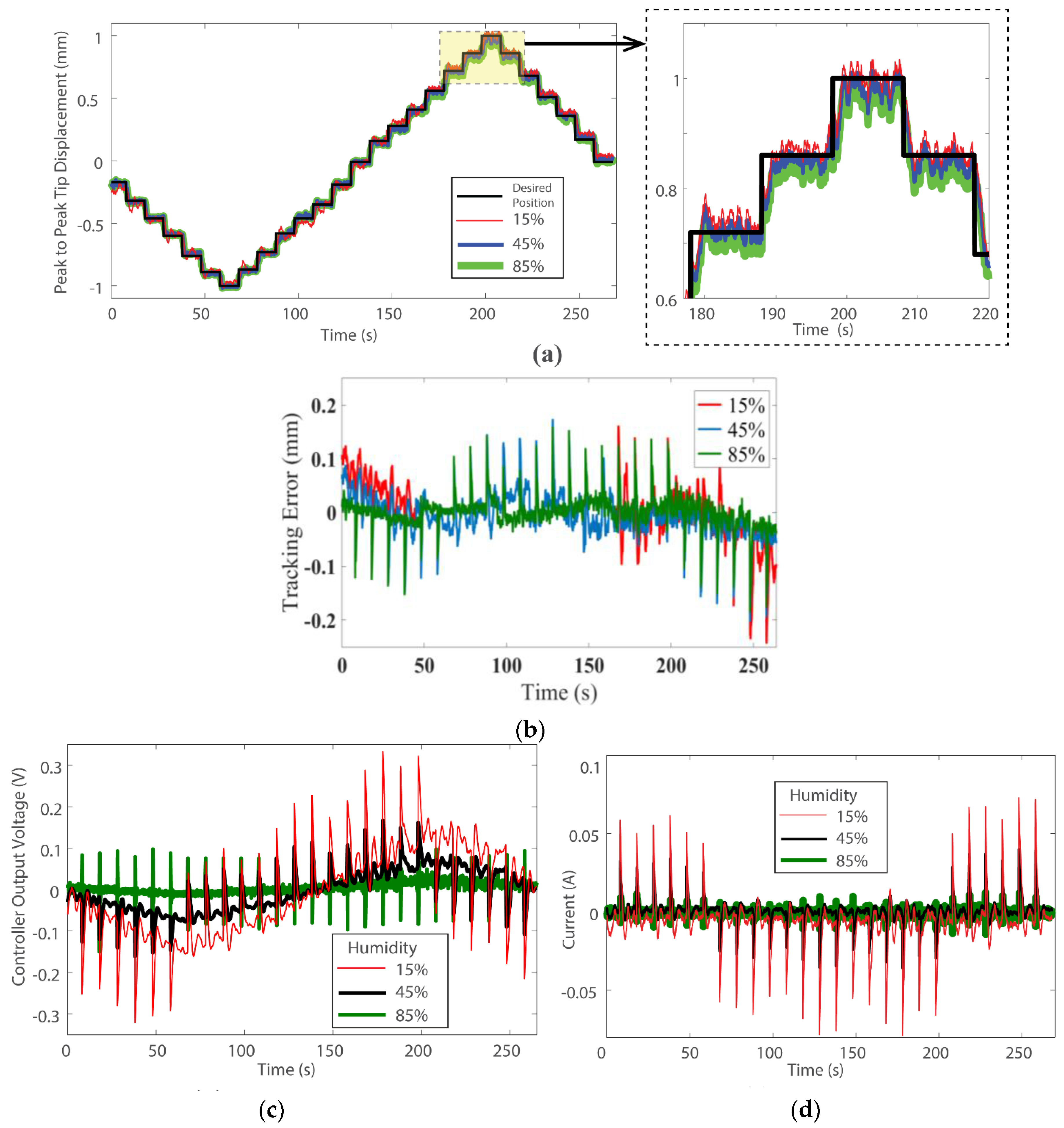
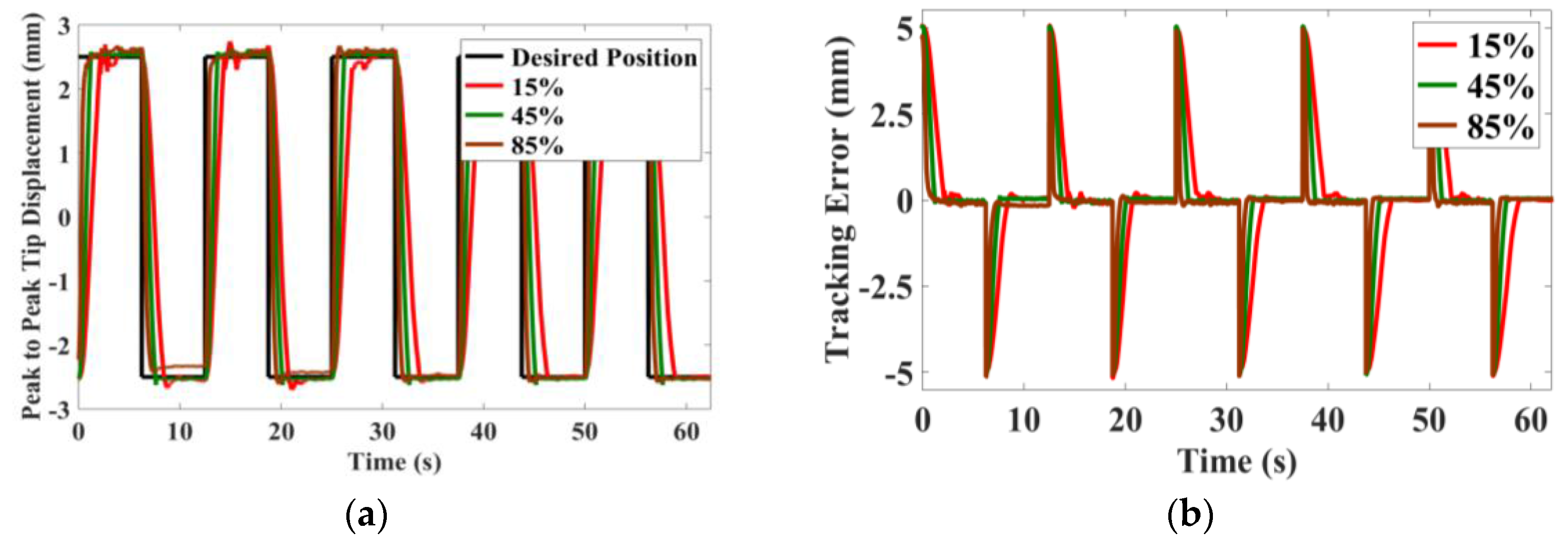
Position control by means of trajectory tracking experiments is conducted with the actuator under different humidity levels. The actuator, at three different random humidity zones, namely low, medium, and high, is selected for testing the system. The results of the sine wave and square wave tracking experiments results are depicted in Figure 10 and Figure 11, respectively. Figure 10a and Figure 11a show the desired reference displacement and the measured peak to peak displacement of the actuator. The tracking error is shown in Figure 10b and Figure 11b. The controller voltage and the current consumed by the actuator during tracking of sine and square wave signals are shown in Figures 10c,d and 11c,d. Figure 12a shows the multistep tracking control of the actuator with each step being 0.14 mm and the tracking error is shown in Figure 12b. The results show the precise tracking performance of the proposed controller with the error limited to 10% over the whole humidity range. The result demonstrates the tracking capability and reliability of the developed model and control scheme under varying humidity conditions. The controller voltage and current consumed by the actuator during tracking of the multistep waveform are shown in Figure 12c,d.
From Figure 10a, for tracking control of sine waves, the controller optimally applies a voltage of about 2 V at 15% and less than 0.5 V at 85% humidity. In a similar fashion for the other tracking results, the voltage applied at lower humidity is far higher than at higher humidity for the same displacement. The actuator consumes less current at higher humidities than at lower humidities. This indicates that under humid conditions, the actuator operates at a higher efficiency. One reason for this effect is that under increased humidity levels, the mechanical stiffness of the actuator or its components is reduced drastically [19]. This allows for effortless bending of the laminate.
Also, at higher humidity levels, the actuator speed of response is higher, which is quite evident from the results of square wave tracking as shown in Figure 11a. The rise time of the actuator is 1.93 s, 1.08 s, and 0.52 s for 15%, 45%, and 85%, respectively. The lower actuation speed is due to the reduced speed of ion transport mechanisms in less humid environments. In order to compensate for that, the controller applies a maximum voltage of 3 V for several seconds, while at high humidity conditions, the control voltage peaks only for a short duration.
7. Conclusions
This work reports on modelling and control of ionic electroactive polymer actuators with porous carbon electrodes under varying humid environments. The impact of humidity on the properties of the actuator is studied through mechanical frequency response analysis and impedance spectroscopy study. To develop an adaptable model to capture the varying dynamics of the actuator under changing environmental conditions, the neural network method is used with humidity as one of the input parameters. Finally, a closed loop control system based on the gain-scheduled model predictive controller is designed for robust position control of the actuator at different humidity levels. The developed model and controller are experimentally verified and found to be well capable of predicting and controlling the actuator under humidity conditions varying in the range of 10%–90%.
Acknowledgments
The research was supported by European Union’s Horizon 2020 research and innovation program under the Marie Sklodowska Curie grant agreement No. 641822, and by the Institutional Research Funding project IUT20-24 from the Estonian Research Council.
Author Contributions
Sunjai Nakshatharan is the corresponding author and is responsible for developing a model and conducting control system experiments and writing the manuscript. Veiko Vunder, Urmas Johnson, Andres Punning contributed in studying and conducting preliminary experiments to understand the effects of humidity on the mechanical and electrical performance of the actuator and also involved in improving the writing of the manuscript. Inga Põldsalu is responsible for the fabrication of the actuators. Alvo Aabloo involved in analyzing the model and experimental results and also involved in improving the writing of the manuscript.
Conflicts of Interest
The authors declare no conflict of interest.
References
- Yeom, S.-W.; Oh, I.-K. A biomimetic jellyfish robot based on ionic polymer metal composite actuators. Smart Mater. Struct. 2009, 18, 085002. [Google Scholar]
- Palmre, V.; Hubbard, J.J.; Fleming, M.; Pugal, D.; Kim, S.; Kim, K.J.; Leang, K.K. An IPMC-enabled bio-inspired bending/twisting fin for underwater applications. Smart Mater. Struct. 2013, 22, 014003. [Google Scholar]
- Chen, Z.; Shatara, S.; Tan, X. Modeling of biomimetic robotic fish propelled by an ionic polymer–metal composite caudal fin. IEEE/ASME Trans. Mechatron. 2010, 15, 448–459. [Google Scholar] [CrossRef]
- Lumia, R.; Shahinpoor, M. IPMC microgripper research and development. J. Phys. Conf. Ser. 2008, 127, 012002. [Google Scholar] [CrossRef]
- McDaid, A.J. Ionic Polymer Metallic Composite Transducers for Biomedical Robotics Applications; IFSA Publishing: Barcelona, Spain, 2014. [Google Scholar]
- Fang, B.K.; Ju, M.S.; Lin, C.C.K. A new approach to develop ionic polymer–metal composites (IPMC) actuator: Fabrication and control for active catheter systems. Sens. Actuators A Phys. 2007, 137, 321–329. [Google Scholar] [CrossRef]
- Chang, Y.-C.; Kim, W.-J. Aquatic ionic-polymer-metal-composite insectile robot with multi-DOF legs. IEEE/ASME Trans. Mechatron. 2013, 18, 547–555. [Google Scholar] [CrossRef]
- Must, I.; Kaasik, F.; Põldsalu, I.; Mihkels, L.; Johanson, U.; Punning, A.; Aabloo, A. Ionic and Capacitive Artificial Muscle for Biomimetic Soft Robotics. Adv. Eng. Mater. 2015, 17, 84–94. [Google Scholar] [CrossRef]
- Nguyen, K.T.; Ko, S.Y.; Park, J.-O.; Park, S. Terrestrial walking robot with 2DoF ionic polymer–metal composite (IPMC) legs. IEEE/ASME Trans. Mechatron. 2015, 20, 2962–2972. [Google Scholar] [CrossRef]
- Mutlu, R.; Alici, G.; Li, W. A Soft Mechatronic Microstage Mechanism Based on Electroactive Polymer Actuators. IEEE/ASME Trans. Mechatron. 2016, 21, 1467–1478. [Google Scholar] [CrossRef]
- Bennett, M.D.; Leo, D. Ionic liquids as stable solvents for ionic polymer transducers. Sens. Actuators A Phys. 2004, 1, 79–90. [Google Scholar] [CrossRef]
- Must, I.; Vunder, V.; Kaasik, F.; Põldsalu, I.; Johanson, U.; Punning, A.; Aabloo, A. Ionic liquid-based actuators working in air: The effect of ambient humidity. Sens. Actuators B Chem. 2014, 202, 114–122. [Google Scholar] [CrossRef]
- Yang, W.; Choi, H.; Choi, S.; Jeon, M.; Lee, S.Y. Carbon nanotube–graphene composite for ionic polymer actuators. Smart Mater. Struct. 2012, 21, 055012. [Google Scholar] [CrossRef]
- Akle, B.; Nawshin, S.; Leo, D. Reliability of high strain ionomeric polymer transducers fabricated using the direct assembly process. Smart Mater. Struct. 2007, 16, S256–S261. [Google Scholar] [CrossRef]
- Landi, B.J.; Raffaelle, R.P.; Heben, M.J.; Alleman, J.L.; VanDerveer, W.; Cennett, T. Single wall carbon nanotube–Nafion composite actuators. Nano Lett. 2002, 2, 1329–1332. [Google Scholar] [CrossRef]
- Brunetto, P.; Fortuna, L.; Giannone, P.; Graziani, S.; Strazzeri, S. Static and Dynamic Characterization of the Temperature and Humidity Influence on IPMC Actuators. IEEE Trans. Instrum. Meas. 2010, 59, 893–908. [Google Scholar] [CrossRef]
- Shoji, E.; Hirayama, D. Effects of Humidity on the Performance of Ionic Polymer−Metal Composite Actuators: Experimental Study of the Back-Relaxation of Actuators. J. Phys. Chem. B 2007, 111, 11915–11920. [Google Scholar] [CrossRef] [PubMed]
- Must, I.; Johanson, U.; Kaasik, F.; Põldsalu, I.; Punning, A.; Aabloo, A. Charging a supercapacitor-like laminate with ambient moisture: From a humidity sensor to an energy harvester. Phys. Chem. Chem. Phys. 2013, 15, 9605–9614. [Google Scholar] [CrossRef] [PubMed]
- Vunder, V.; Hamburg, E.; Johanson, U.; Punning, A.; Aabloo, A. Effect of ambient humidity on ionic electroactive polymer actuators. Smart Mater. Struct. 2016, 25, 055038. [Google Scholar] [CrossRef]
- Pugal, D.; Kim, K.J.; Aabloo, A. An explicit physics-based model of ionic polymer-metal composite actuators. J. Appl. Phys. 2011, 110, 084904. [Google Scholar] [CrossRef]
- Zhu, Z.; Asaka, K.; Chang, L.; Takagi, K.; Chen, H. Multiphysics of ionic polymer-metal composite actuator. J. Appl. Phys. 2013, 114, 084902. [Google Scholar] [CrossRef]
- Nemat-Nasser, S.; Li, J.Y. Electromechanical response of ionic polymer-metal composites. J. Appl. Phys. 2000, 87, 3321. [Google Scholar] [CrossRef]
- Chen, Z.; Tan, X. A Control-Oriented and Physics-Based Model for Ionic Polymer-Metal Composite Actuators. IEEE/ASME Trans. Mechatron. 2008, 13, 519–529. [Google Scholar] [CrossRef]
- Ahn, K.K.; Truong, D.Q.; Nam, D.N.C.; Yoon, J.I.; Yokota, S. Position control of ionic polymer metal composite actuator using quantitative feedback theory. Sens. Actuators A Phys. 2010, 159, 204–212. [Google Scholar] [CrossRef]
- Vunder, V.; Itik, M.; Põldsalu, I.; Punning, A.; Aabloo, A. Inversion-based control of ionic polymer–metal composite actuators with nanoporous carbon-based electrodes. Smart Mater. Struct. 2014, 23, 025010. [Google Scholar] [CrossRef]
- Akle, B.J.; Bennett, M.D.; Leo, D.J. High-strain ionomeric–ionic liquid electroactive actuators Sens. Actuators A Phys. 2006, 126, 173–181. [Google Scholar] [CrossRef]
- Thinh, N.T.; Yang, Y.S.; Oh, I.-K. Adaptive neuro-fuzzy control of ionic polymer metal composite actuators. Smart Mater. Struct. 2009, 18, 065016. [Google Scholar] [CrossRef]
- De Luca, V.; Hosseini-Asl, E.; Graziani, S.; Zurada, J.M. Neural modeling of relative humidity on IP2C vibrating transducer. Procedia Eng. 2014, 87, 424–427. [Google Scholar] [CrossRef]
- Truong, Q.D.; Ahn, K.K. Design and Verification of a Non-linear Black-Box Model for Ionic Polymer Metal Composite Actuators. J. Intell. Mater. Syst. Struct. 2011, 22, 253–269. [Google Scholar] [CrossRef]
- Truong, Q.D.; Ahn, K.K. Modeling of an ionic polymer metal composite actuator based on an extended kalman filter trained neural network. Smart Mater. Struct. 2014, 23, 074008. [Google Scholar] [CrossRef]
- Kang, S.; Shin, J.; Kim, S.J.; Kim, H.J.; Kim, Y.H. Robust control of ionic polymer–metal composites. Smart Mater. Struct. 2007, 16, 2457. [Google Scholar] [CrossRef]
- Fang, Y.; Tan, X.; Alici, G. Robust Adaptive Control of Conjugated Polymer Actuators. IEEE Trans. Control Syst. Technol. 2008, 16, 600–612. [Google Scholar] [CrossRef]
- Chen, X.; Su, C.Y. Adaptive Control for Ionic Polymer-Metal Composite Actuators. IEEE Tran. Syst. Man Cybern. Syst. 2016, 46, 1468–1477. [Google Scholar] [CrossRef]
- Akle, B.J.; Bennett, M.D.; Leo, D.J.; Wiles, K.B.; McGrath, J.E. Direct assembly process: A novel fabrication technique for large strain ionic polymer transducers. J. Mater. Sci. 2007, 42, 7031–7041. [Google Scholar] [CrossRef]
- Palmre, V.; Brandell, D.; Mäeorg, U.; Torop, J.; Volobujeva, O.; Punning, A.; Johanson, U.; Kruusmaa, M.; Aabloo, A. Nanoporous carbon-based electrodes for high strain ionomeric bending actuators. Smart Mater. Struct. 2009, 18, 095028. [Google Scholar] [CrossRef]
- Wang, L. Model Predictive Control System Design and Implementation Using Mat-Lab-Advances in Industrial Control; Springer: London, UK, 2008. [Google Scholar]
- Baughman, D.R.; Liu, Y.A. Neural Networks in Bioprocessing and Chemical Engineering; Academic Press Inc.: London, UK, 1996. [Google Scholar]
- Nguyen, D.H.; Widrow, B. Neural networks for self-learning control systems. IEEE Control Syst. Mag. 1990, 10, 18–23. [Google Scholar] [CrossRef]
- Svozil, D.; Kvasnicka, V.; Pospichal, J. Introduction to multilayer feed forward neural networks. Chemom. Intell. Lab. 1997, 39, 43–62. [Google Scholar] [CrossRef]
- Yu, H.; Wilamowski, B.M. Levenberg Marquardt Training. In the Industrial Electronics Handbook, Vol.5 –Intelligent Systems, 2nd ed.; Wilamowski, B.M., Irwin, J.D., Eds.; CRC Press: Boca Raton, FL, USA, 2011; Chapter 12. [Google Scholar]
- Barlas, T.K.; Van der Veen, G.J.; Van Kuik, G.A.M. Model predictive control for wind turbines with distributed active flaps: Incorporating inflow signals and actuator constraints. Wind Energy 2012, 15, 757–771. [Google Scholar] [CrossRef]
- Stein, G.; Hartmann, G.L.; Hendrick, R. Adaptive control laws for F-8 flight Test. IEEE Trans. Autom. Control 1997, 22, 758–767. [Google Scholar] [CrossRef]
- Athans, M.; Castanon, C.; Dunn, K.; Greene, C.; Wing, L., Jr.; Sandell, N.; Willsky, A.M. The stochastic control of the F-8C aircraft using a multiple model adaptive control (MMAC) method—part I: Equilibrium flight. IEEE Trans. Autom. Control 1977, 22, 768–780. [Google Scholar] [CrossRef]
- Mohanty, S. Artificial neural network based system identification and model predictive control of a flotation column. J. Process Control 2009, 19, 991–999. [Google Scholar] [CrossRef]
- Rugh, W.J.; Shamma, J.S. Research on gain scheduling. Automatica 2000, 36, 1401–1425. [Google Scholar] [CrossRef]
- Whatley, M.J.; Pott, D.C. Adaptive gain improves reactor control. Hydrocarb. Process 1984, 63, 75–78. [Google Scholar]
Figure 1.
(a) Scanning electron microscope (SEM) micrograph of the cross-section of the actuator; (b) Graphical representation of the actuator.
Figure 1.
(a) Scanning electron microscope (SEM) micrograph of the cross-section of the actuator; (b) Graphical representation of the actuator.

Figure 2.
Experimental setup.

Figure 3.
Mechanical frequency response analysis: (a) Peak to peak displacement measured at different humidity conditions from 0.01 Hz to 3 Hz; (b) Impedance spectroscopy results at different humidity from 0.01 Hz to 1000 Hz.
Figure 3.
Mechanical frequency response analysis: (a) Peak to peak displacement measured at different humidity conditions from 0.01 Hz to 3 Hz; (b) Impedance spectroscopy results at different humidity from 0.01 Hz to 1000 Hz.
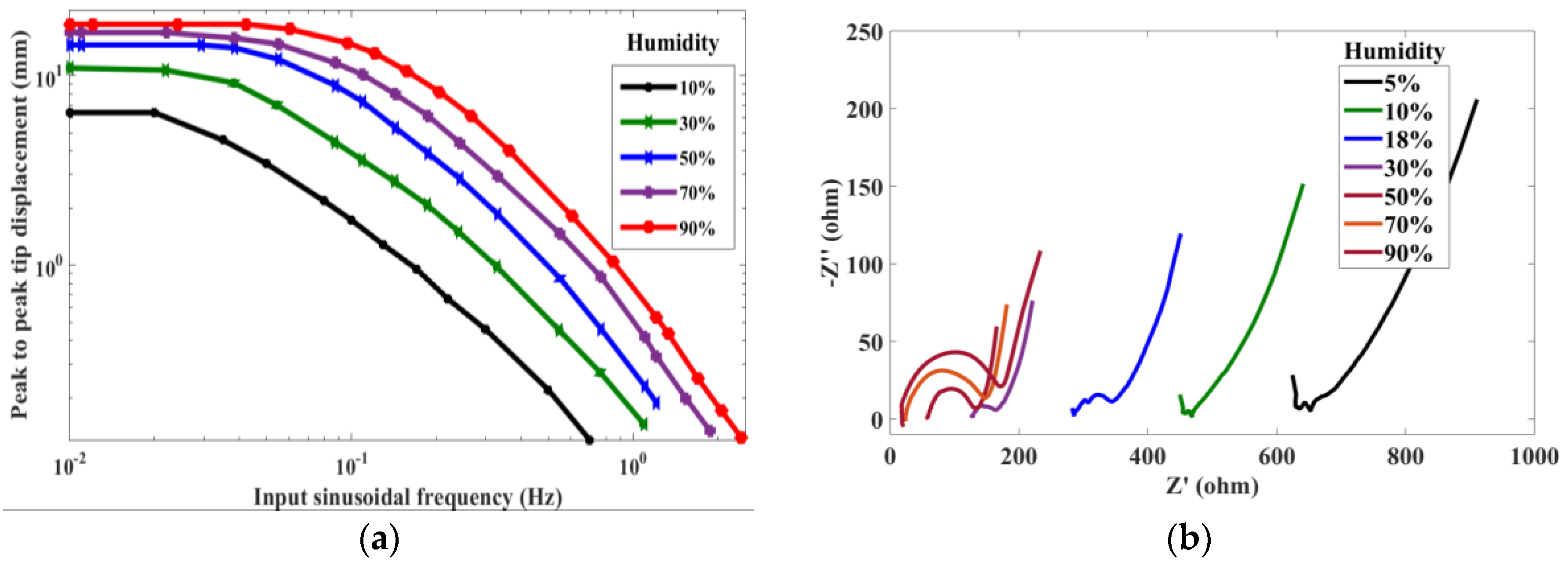
Figure 4.
Electrical equivalent circuit of ionic polymer actuator with charge transfer reaction.
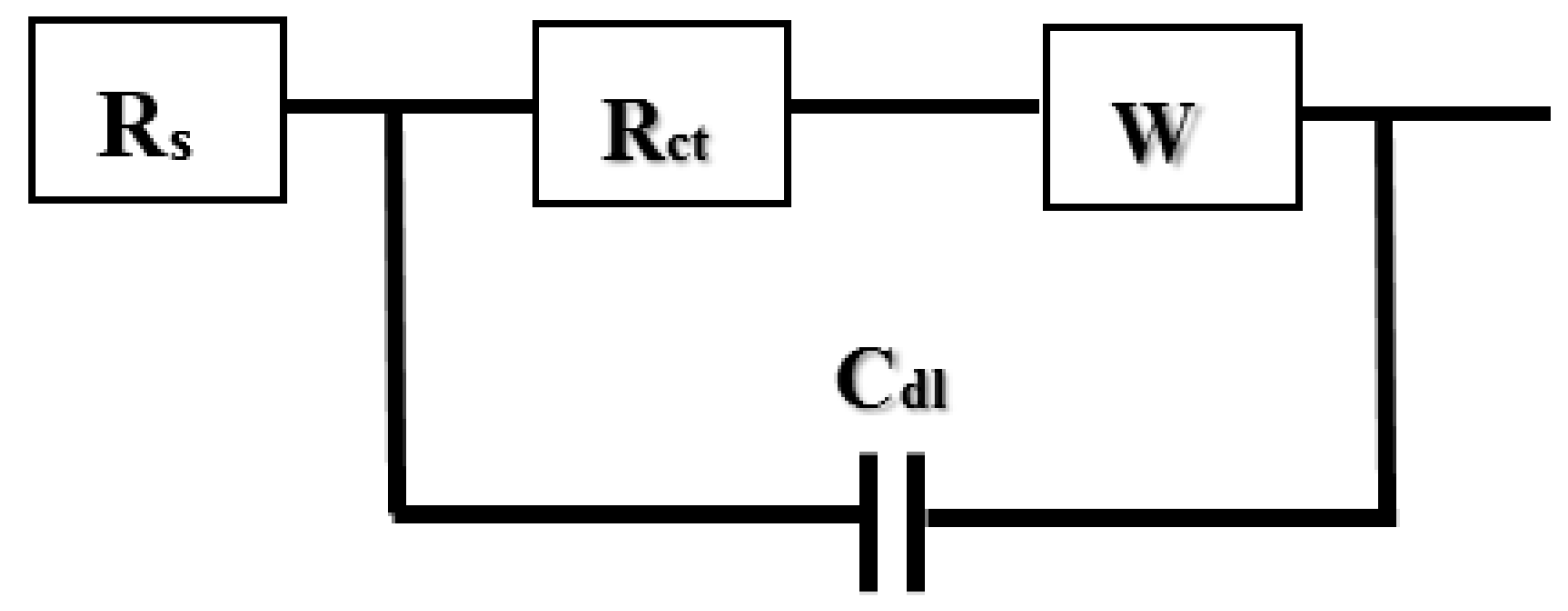
Figure 5.
Multilayer feed forward neural network schematics depicting input–output parameters.

Figure 6.
Neural network training schematics.
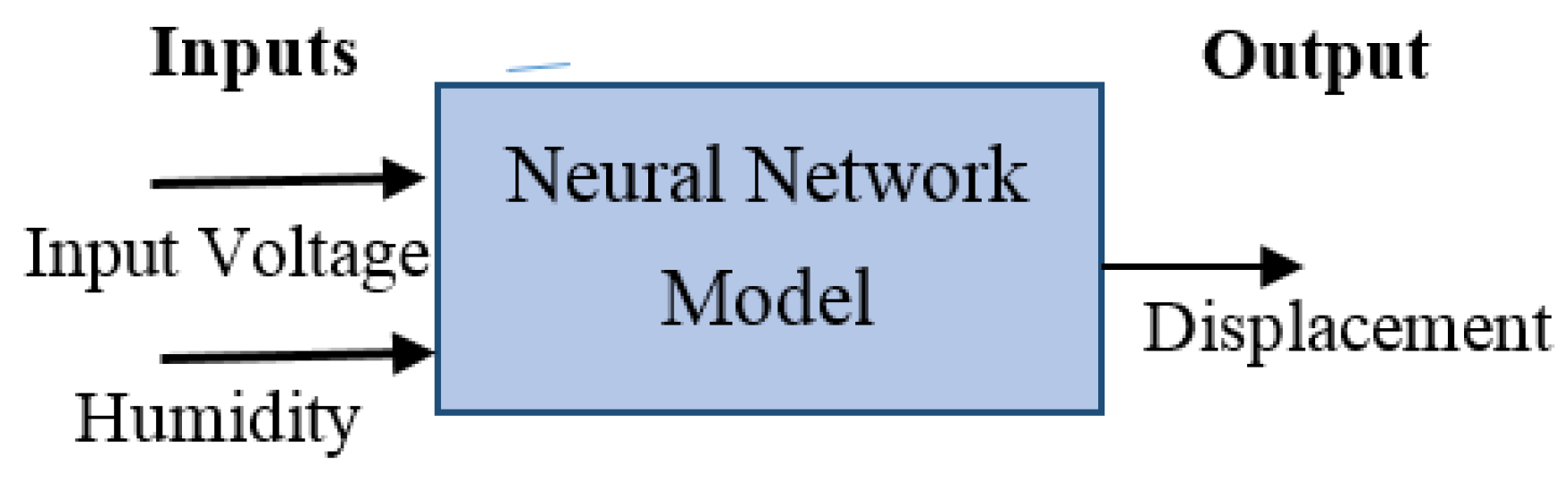
Figure 7.
(a) Sample data used for modelling, (b) comparison of neural network model and experimental output, (c) model error.
Figure 7.
(a) Sample data used for modelling, (b) comparison of neural network model and experimental output, (c) model error.

Figure 8.
Controller schematics.

Figure 9.
(a) Schematic of gain-scheduled controller; (b) weight vs. humidity.
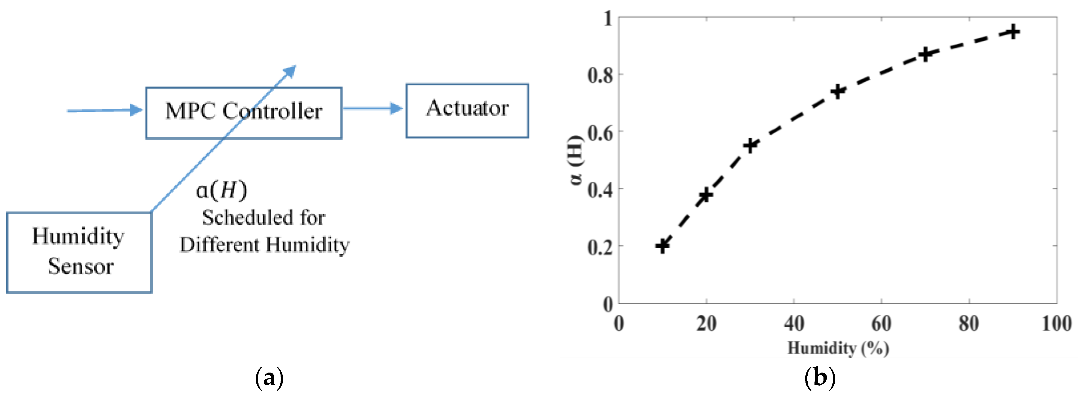
Figure 10.
(a) Sine trajectory tracking; (b) Tracking error; (c) Controller output; (d) Current.
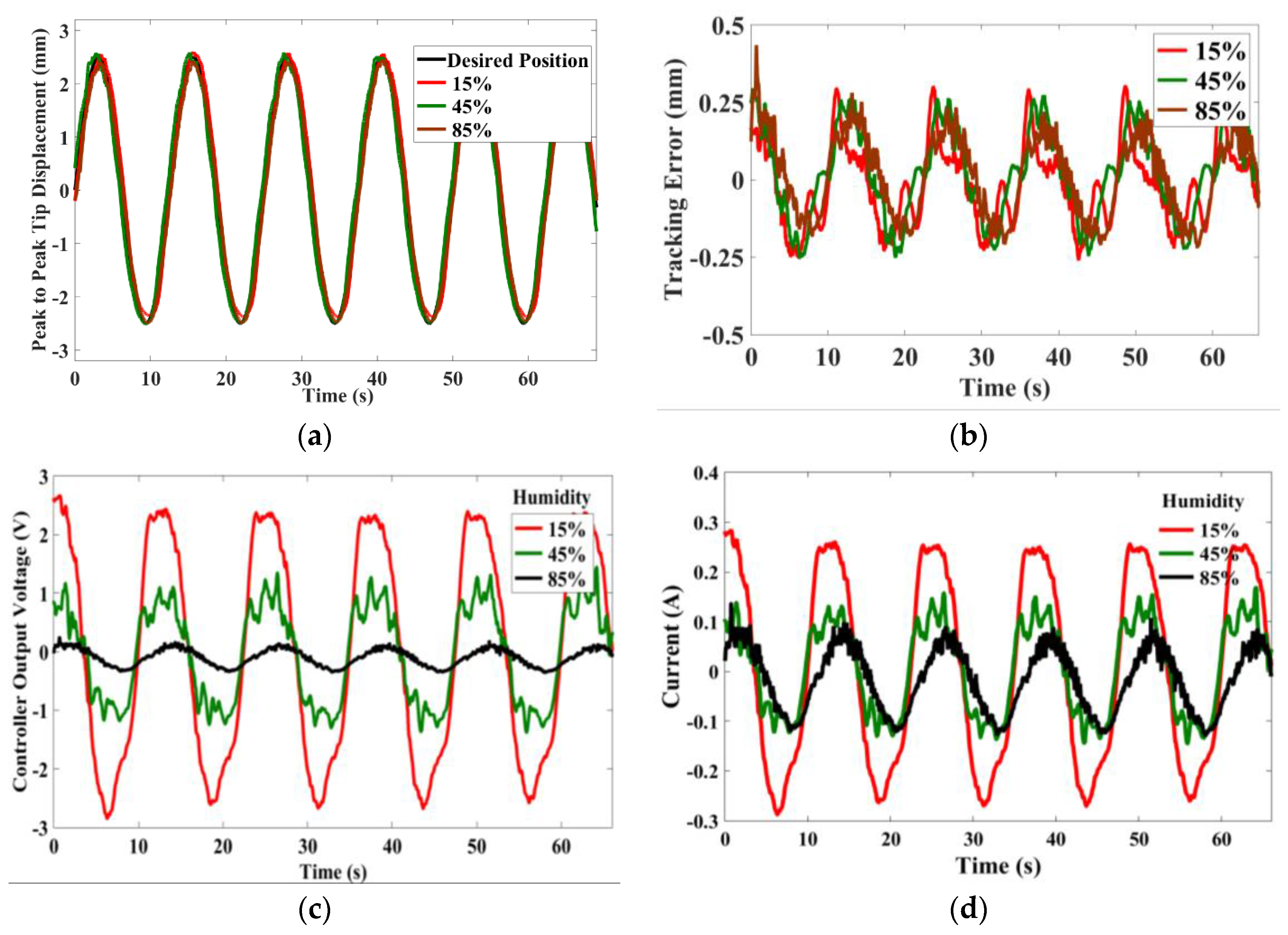
Figure 11.
(a) Square trajectory tracking; (b) Tracking error; (c) Controller output; (d) Current.

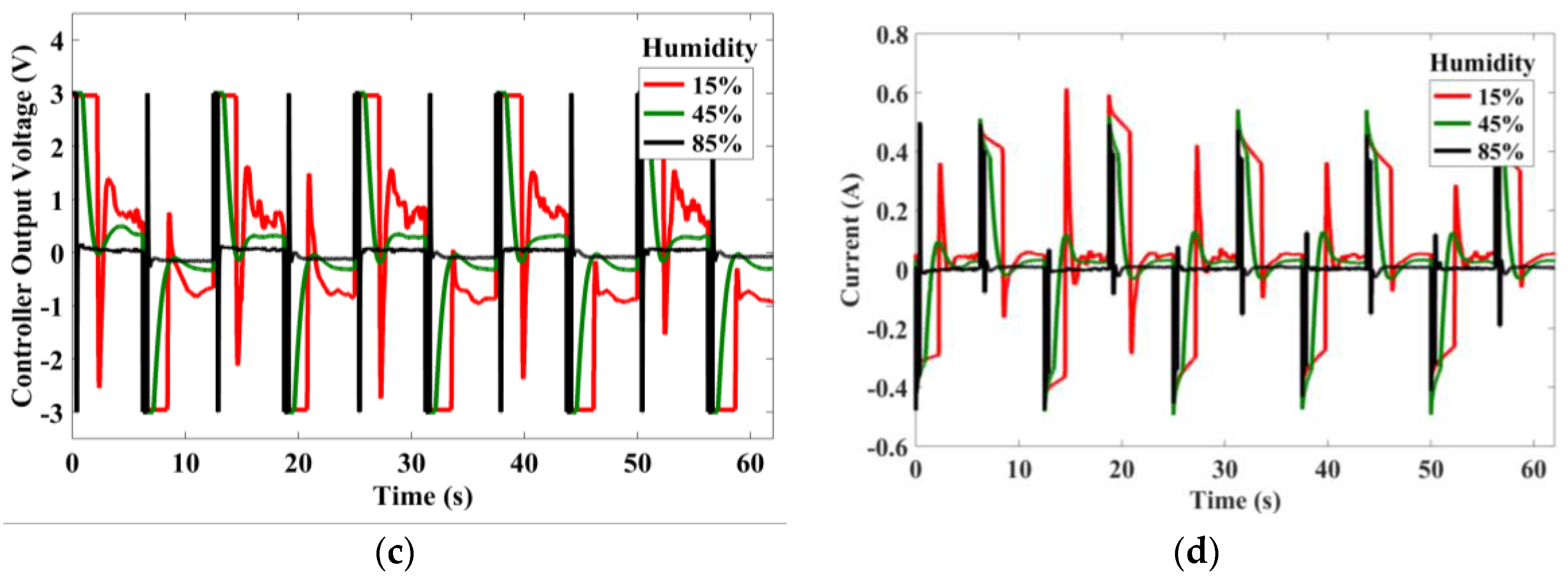
Figure 12.
Multistep tracking: (a) Displacement; (b) Tracking error; (c) Controller output voltage; (d) Current.
Figure 12.
Multistep tracking: (a) Displacement; (b) Tracking error; (c) Controller output voltage; (d) Current.

Table 1.
Equivalent circuit parameters.
| Humidity | Electrolyte Resistance (Ω) RS | Charge Transfer Resistance (Ω) Rct | Double Layer Capacitance (µF) Cdl |
|---|---|---|---|
| 10% | 449.21 | 14.37 | 3.44 |
| 30% | 136.96 | 43.04 | 14.59 |
| 50% | 58.41 | 80.59 | 22.93 |
| 70% | 23.27 | 141.73 | 70.27 |
| 90% | 18.45 | 179.25 | 248.58 |
Table 2.
Control parameters.
| Parameter | Symbol | Value |
|---|---|---|
| Sample Time | ts | 0.1 s |
| Prediction Horizon | NH | 40 (=4 s) |
| Control Horizon | Nc | 10 (=1 s) |
| Humidity at | ||
| 10% = 0.2 | ||
| Control Gain Scheduling | 20% = 0.38 | |
| Tuning Weights | 30% = 0.55 | |
| 50% = 0.74 | ||
| 70% = 0.87 | ||
| 90% = 0.95 |
© 2018 by the authors. Licensee MDPI, Basel, Switzerland. This article is an open access article distributed under the terms and conditions of the Creative Commons Attribution (CC BY) license (http://creativecommons.org/licenses/by/4.0/).
Share and Cite
MDPI and ACS Style
Nakshatharan, S.S.; Vunder, V.; Põldsalu, I.; Johanson, U.; Punning, A.; Aabloo, A. Modelling and Control of Ionic Electroactive Polymer Actuators under Varying Humidity Conditions. Actuators 2018, 7, 7. https://doi.org/10.3390/act7010007
AMA Style
Nakshatharan SS, Vunder V, Põldsalu I, Johanson U, Punning A, Aabloo A. Modelling and Control of Ionic Electroactive Polymer Actuators under Varying Humidity Conditions. Actuators. 2018; 7(1):7. https://doi.org/10.3390/act7010007
Chicago/Turabian StyleNakshatharan, S. Sunjai, Veiko Vunder, Inga Põldsalu, Urmas Johanson, Andres Punning, and Alvo Aabloo. 2018. "Modelling and Control of Ionic Electroactive Polymer Actuators under Varying Humidity Conditions" Actuators 7, no. 1: 7. https://doi.org/10.3390/act7010007
Note that from the first issue of 2016, this journal uses article numbers instead of page numbers. See further details here.