A 3D Printed Linear Pneumatic Actuator for Position, Force and Impedance Control

Robotics and Motion Laboratory, Department of Mechanical Engineering, The University of Texas at San Antonio, One UTSA Circle, San Antonio, TX 78249, USA
*
Author to whom correspondence should be addressed.
Actuators 2018, 7(2), 24; https://doi.org/10.3390/act7020024
Submission received: 27 April 2018
/
Revised: 18 May 2018
/
Accepted: 22 May 2018
/
Published: 24 May 2018
(This article belongs to the Special Issue Pneumatic Actuators)
Abstract
:Although 3D printing has the potential to provide greater customization and to reduce the costs of creating actuators for industrial applications, the 3D printing of actuators is still a relatively new concept. We have developed a pneumatic actuator with 3D-printed parts and placed sensors for position and force control. So far, 3D printing has been used to create pneumatic actuators of the bellows type, thus having a limited travel distance, utilizing low pressures for actuation and being capable of only limited force production and response rates. In contrast, our actuator is linear with a large travel distance and operating at a relatively higher pressure, thus providing great forces and response rates, and this the main novelty of the work. We demonstrate solutions to key challenges that arise during the design and fabrication of 3D-printed linear actuators. These include: (1) the strategic use of metallic parts in high stress areas (i.e., the piston rod); (2) post-processing of the inner surface of the cylinder for smooth finish; (3) piston head design and seal placement for strong and leak-proof action; and (4) sensor choice and placement for position and force control. A permanent magnet placed in the piston head is detected using Hall effect sensors placed along the length of the cylinder to measure the position, and pressure sensors placed at the supply ports were used for force measurement. We demonstrate the actuator performing position, force and impedance control. Our work has the potential to open new avenues for creating less expensive, customizable and capable actuators for industrial and other applications.
1. Introduction
Pneumatic actuators are preferred over hydraulic actuators in applications that have moderate power requirements because they are environmentally safe (compressed air versus high pressure oil), require minimal maintenance and have high durability. Yet, pneumatic actuators are not widely implemented. We hypothesize the reasons might be because: (1) commercially available actuators are available only in specific configurations (i.e., size, material, power output); and (2) of the relatively high cost of position- and force-controlled pneumatic actuators. Our work attempts to narrow the technology gap through the use of additive manufacturing, specifically 3D printing. We demonstrate that it is possible to print a piston-type linear pneumatic actuator with low friction and position and force control to create a relatively inexpensive customized pneumatic actuator.
The most common pneumatic actuators utilize compressed air to drive a piston along a cylindrical tube. Such actuators are generally made from metal (e.g., stainless steel or aluminum), as they require higher endurance to withstand repeated loading (e.g., fatigue failure). The most common and inexpensive pneumatic actuators have no sensors (i.e., operate open loop) and can shuffle between fully-extended or fully-retracted configurations. Adding force/pressure sensors and providing variable flow rates increases the applicability of such actuators to control applications, but adds to the cost and complexity of both the actuator and the control system.
Position sensors for pneumatics are available in either contact or non-contact configurations [1]. Contact position sensors use a linear resistive transducer placed along the length of the cylinder. The piston head is fitted with a wiper that contacts the linear resistive transducer. The resistance changes as the piston moves, thus producing an output voltage proportional to the resistance and thus the piston displacement. Resistive sensors are inexpensive and easy to mount, but prone to contamination, wear and tear. Typical non-contact sensing uses a permanent magnet mounted on the piston head and magnetic switches around the cylinder to measure the strength of the magnetic field. The advantage of such a system is that it is more durable than resistive sensing, but is more expensive and does not work well when the the cylinder has ferric materials that will interfere with the magnetic field. Other work in non-contact sensing involves the detection of changes in the magnetic field in primary and secondary coils placed around the cylinder as the magnet moves or the use of an array of Hall effect sensors placed along the cylinder length to measure the magnetic field [2]. Vyhnanek et al. [3] used an alternate measurement system that does not require a permanent magnet, but needs a ferromagnetic piston rod. The method consists of placing excitation coils along the length of the cylinder, which changes the magnetic field due to interaction with the ferromagnetic piston rod. The magnetic field is then detected using fluxgate sensors placed along the length of the cylinder.
Forces on the actuator may be measured directly using a force sensor mounted on the output shaft [4]. The indirect method uses pressure measurements in the two chambers of the cylinder for force estimation [5,6]. Two solid-state sensors are placed in each chamber of the pneumatic cylinder. Then, using the dimensions of the actuator, specifically the cross-sectional area of the cylinder and pressure measurements, it is possible to calculate the force. Note that the direct measurement estimates the forces at the output shaft, while the indirect method is only able to estimate the force just before the output shaft. The forces measured at the output shaft may be smaller than the forces before the output shaft due to inefficiencies (e.g., force of friction). Depending on the application, one of the two methods might be more desirable.
Three-dimensional (3D) printing, a technology that was created in the 1980s, has only recently become economically and technologically feasible for widespread use. The vast majority of work in 3D printing pneumatic actuators has been for soft (compliant) robot applications. For example, Peele et al. [7] have created a pneumatic bellow-type actuator using stereolithography and fabricated an octopus tentacle. Stereolithography is a 3D printing technique that involves shining ultra-violet light on photosensitive polymers, thus solidifying them to create successive 2D layers to build 3D objects. Another advantage of 3D printing is the ability to build an entire system consisting of the structure, the mechanism, the transmission, as well as the actuator without the need for assembly. For example, Maccurdy et al. [8] created a non-assembly hexapod robot that included bellow actuators, gear pumps and soft grippers, all of which were printed as a single integrated assembly using a multi-material printer. The gear pump forces the fluid through the transmission, thus moving the robot legs in a predefined fashion to create forward movement. Wei et al. [9] created a rotary pneumatic stepper actuator. The actuator consists of an inner fixed rotor with gears on its outside and an outer moving rotor with gears on its inside. Three equidistant diaphragm cylinders placed along the outer gear are sequentially activated by compressed air to move the outer gear relative to the inner gear in steps. The main advantage is that the system has low requirements for airtightness. This actuator was printed along with a robotic arm, and a simple pick and place operation was demonstrated.
Sensors for 3D-printed parts can be placed after the printing is completed. A more subtle approach is to embed sensors by stopping the 3D printing process [10]. The benefit of this method is the elimination of the assembly process, thus saving time. However, the approach is more complicated: visual cues need to be set up to stop the printing process to embed actuators, and joints need to be designed so that excess material around the joints can be easily removed post printing. More recently, with the development of newer materials (e.g., conductive elastomer) and printers with multiple material deposition heads, it is possible to co-print the sensor along with the structure. For example, Yang and Chen [11] co-printed a position and pressure sensor within the soft actuator to create a robotic gripper.
Although 3D printing has been used to create soft pneumatic actuators that operate at a relatively low supply pressure, 3D printing has not been used to produce conventional pneumatic actuators such as the piston-cylinder assembly that is able to operate at standard pneumatic supply pressures. This work extends our earlier work on 3D-printed actuators that demonstrated a linear pneumatic ON-OFF actuator [12] for open loop control. Here, in addition, we demonstrate feedback control by integrating appropriate sensors. Creating 3D-printed actuators using plastic filaments and hobby-grade printers is significantly challenging because of the low resolution of hobby-grade printers, leading to: limited strength parts, rough (high friction) surfaces, thus reducing the efficiency, appreciable clearance, leading to leakages, and anisotropy of the parts, resulting in direction-dependent strength. In this research, the challenges are met by using metal in high stress parts, post-processing of the printed surfaces for a smooth finish, piston head design and O-ring placement for a leak-proof piston-cylinder interface.
2. Materials and Methods
2.1. Overall Actuator Design
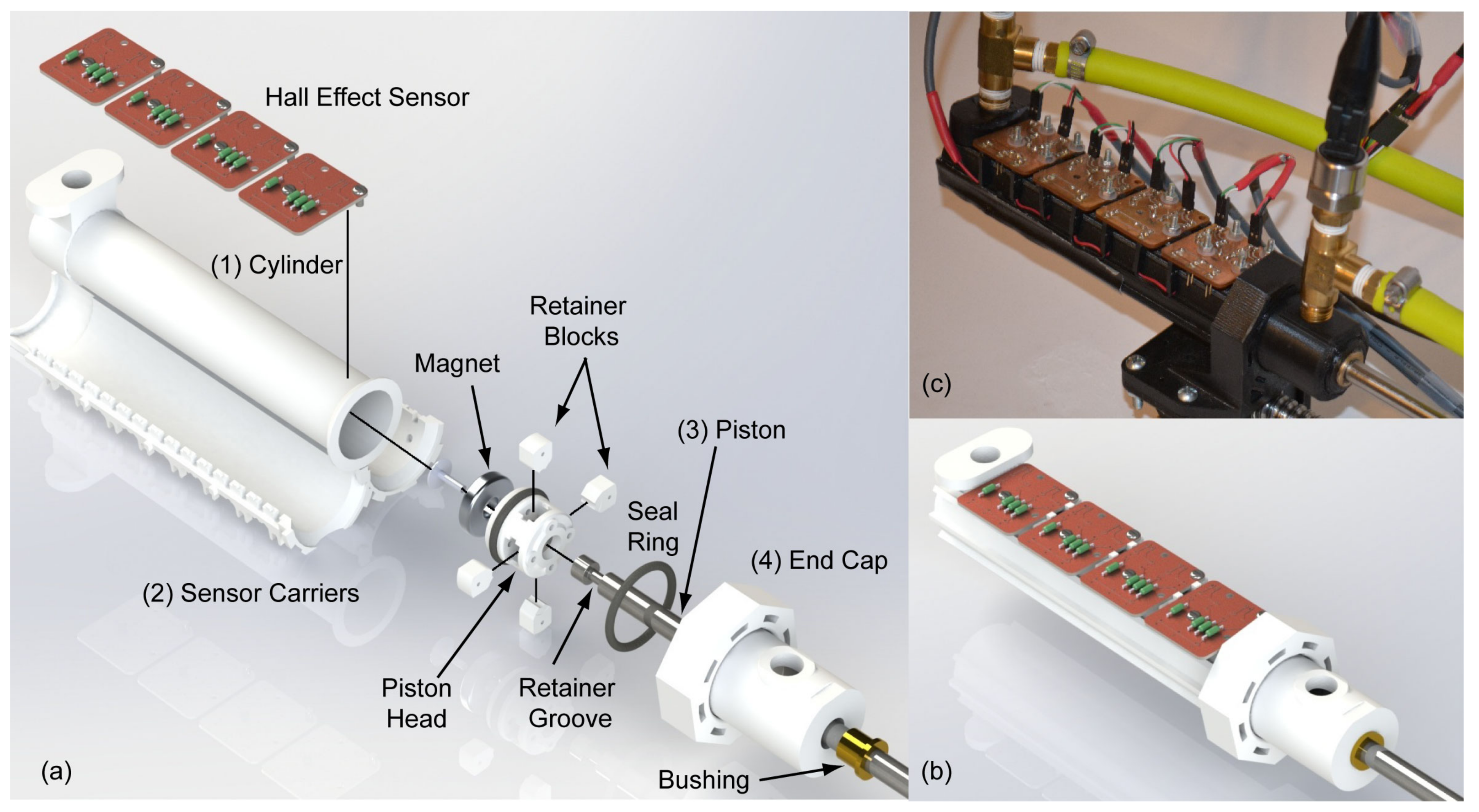
The CAD design and the final 3D-printed linear actuator are shown in Figure 1. The final actuator design had a weight of kg, a bore diameter of cm and a stroke length of cm. The pneumatic cylinder consisted of four main components: (1) a 3D-printed cylinder body; (2) two 3D-printed sensor carriers, positioned around the cylinder to retain the position sensors; (3) a metal piston rod with a 3D-printed piston head; and (4) a 3D-printed end cap with bushings.
2.1.1. Cylinder
The cylinder was 3D printed using the Ultimaker 3 Extended printer using a PolyLactic Acid (PLA) filament. The cylinder consisted of two parts: the cylinder body and the front cap that was printed as a single part to avoid unnecessary sealing requirements. Both parts were printed along the lengthwise direction, thus printing concentric circles to build the body. The thickness of the cylinder body was chosen to be 0.1143 cm. To determine the optimal thickness, we printed multiple short samples with different thicknesses, but the same inner radius. We subjected each cylinder to a static pressure of 100 psi (689.58 kN/m). We found that thicknesses of less than 0.1143 cm lead to excess intra-pore leakage and plastic deformation.
One issue with the 3D printing of the cylinder body was that the inner surface was not sufficiently smooth to allow for low resistance movement of the piston. This was a limitation of our 3D printer, which has a maximum resolution of m or inches. Thus, a mechanical post-processing procedure was used in order to remove a thin surface layer of material to create a smooth surface finish. We 3D printed an arbor with three spring-loaded arms. An aluminum oxide impregnated paper was wound around the arms on the arbor. The arbor was driven by an electric drill and moved along the length of the cylinder on the inner side. First, we sanded the surface with a 400-grit (coarse) abrasive paper and then with a 1000-grit (fine) abrasive paper. During sanding, a copious amount of water was used to remove heat, thus preventing warping and damaging of the 3D-printed part. The resulting bore finish was adequately polished for smooth piston action.
2.1.2. Sensor Carriers
Two 3D-printed sensor carriers were fitted onto the external surface of the cylinder to mount the Hall effect sensors. These carriers were constructed with an interlocked grid configuration with integral interior cavities to reduce the overall weight and printing time. They were attached to the inner bore through the use of interlocking mechanical connectors. Besides restraining the sensors, they served the additional purpose of reinforcing the inner bore.
2.1.3. Piston
The piston consisted of an SAE 304 steel rod shaft with a 3D-printed piston head. The use of a steel rod shaft as opposed to a 3D-printed shaft was due to the ability of the former to handle the high stresses that are generated during the operation. The piston head was fitted with a high strength neodymium magnet. The neodymium magnet was available as an annulus. Thus, the piston head was 3D-printed with an internal threaded hole of a diameter equal to the inner circle of the magnet. A non-ferrous screw was used to secure the magnet to the piston head. In addition, the piston had a groove to mount the seal (O-ring) between the piston and cylinder and to mount four retainer blocks as shown in Figure 1. The magnetic field generated by the magnet was measured by the Hall effect sensors mounted along the length of the cylinder. The output voltages from the Hall effect sensors were calibrated to indicate the position of the piston head relative to the cylinder. The fluoroelastomer seal goes by the trade name Viton and has a Durometer 60A hardness. We found that the chosen seal used in our configuration was extremely effective at sealing the pneumatic piston at pressures up to 150 psig (1034 kN/m).
2.1.4. End Cap
The end cap was 3D printed and designed to seal against the surface on the inner cylinder bore. A brass bushing was embedded at the end of the cap to allow mechanical force to be transferred outside of the cylinder while maintaining elevated pressures inside.
2.1.5. Design Safety Considerations for 3D Printing
Due to the nature of 3D-printed materials, with strength being a factor of multiple variables that are not readily measured without specialized equipment, such as print temperature, print speed, printer extrusion consistency, ambient temperature and selected thermoplastic material, two practices are highly recommended: over-construction and pressure testing.
Over-construction is the practice of constructing a part such that critical thicknesses (the thicknesses of parts that would be subject to bursting at elevated pressures) are over-designed to an extent that the operator can be sure that, to a high level of certainty, they will not fail under normal circumstances. Over-construction can also take the form of designing exterior pieces. For example the sensor carrier was capable of containing fragments of the inner pressure bore should failure occur. All the utilized wall thicknesses in the final design were at least twice the thicknesses of pressure-tested parts. Note that the test parts were tested up to 150 psig (1034 kN/m) in static loading and did not show any signs of catastrophic failure.
Pressure testing should be performed with test parts printed on the same 3D printer that will be used for the pneumatic cylinder, with a test wall thickness up to the planned bore wall thickness. Pressure testing was performed with test cylinders of -cm, -cm, -cm and -cm wall thickness with bore diameter held constant at cm. Sample cylinders where submerged in a water bath to capture any fragments in the event of failure and cyclically charged and discharged from 0–150 psig (1034 kN/m) for a period of 10 s for 20 cycles. No part failed or deformed plastically, but a significant increase in interlayer pore leakage was observed as wall thickness was decreased, with the leakage rate for the -cm wall thickness cylinder approaching cubic meters per minute for a 5 cm-long test cylinder. None of the pressure-tested samples possessed post-treated bores.
2.2. Experimental Apparatus
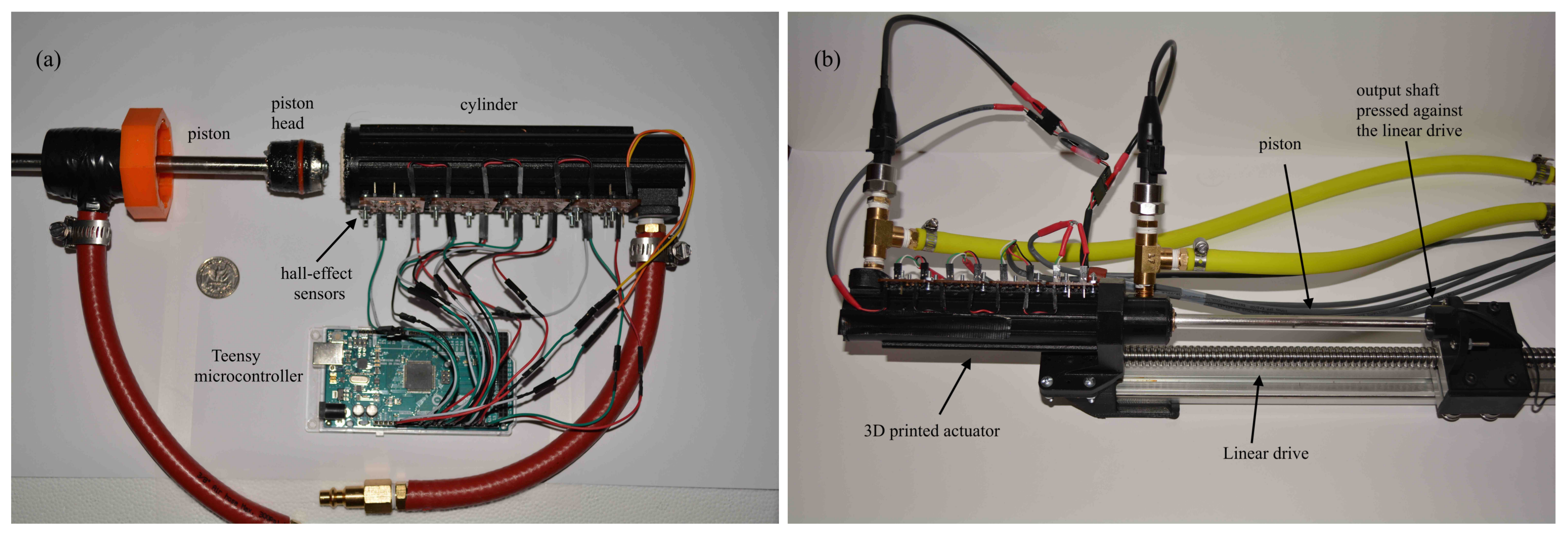
The experimental setup used is shown in Figure 2. The apparatus consisted of four main components: (1) sensors; (2) a pneumatic proportional flow valve; (3) a micro-controller; and (4) a commercially produced lead screw drive.
2.2.1. Sensors
The actuator had non-contact position sensors to measure the piston travel. The actuator also had 2 pressure sensors in the actuator chambers that were calibrated to measure the force.
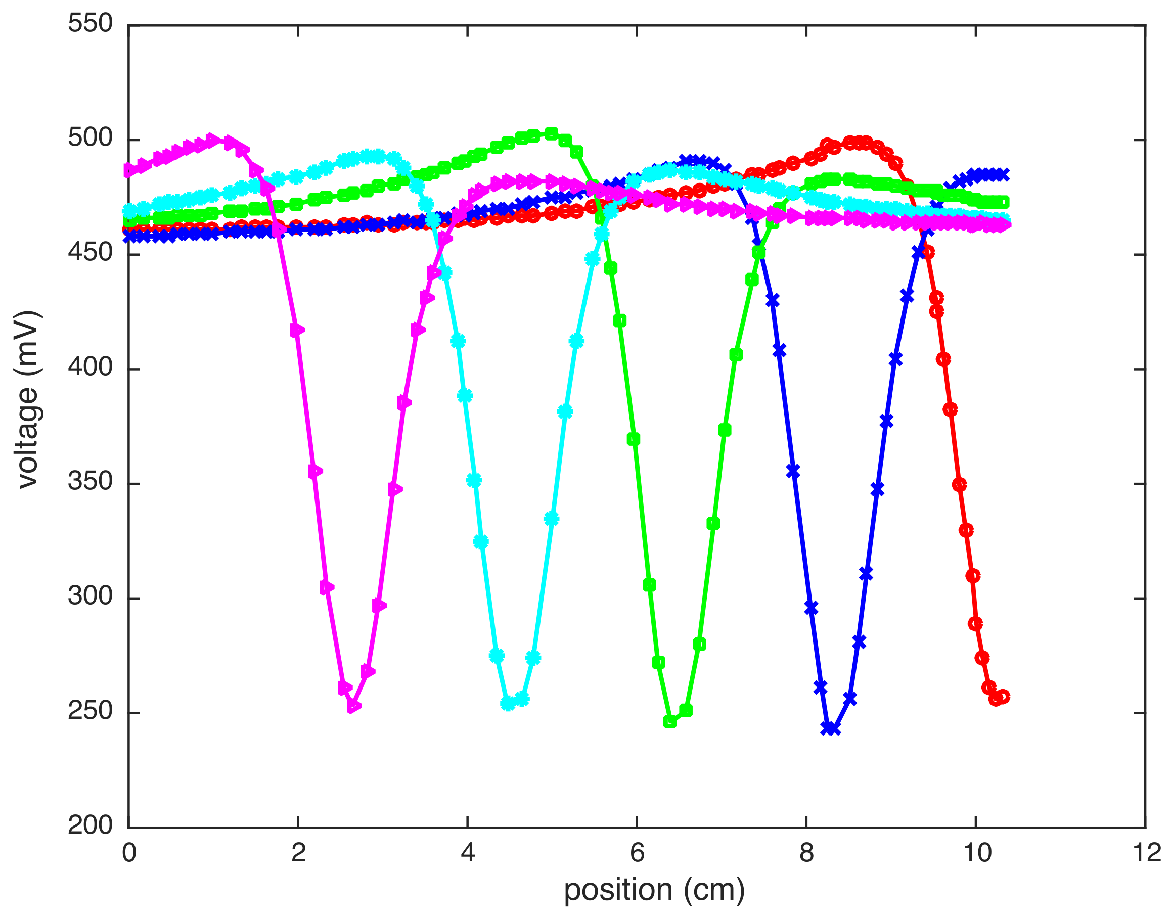
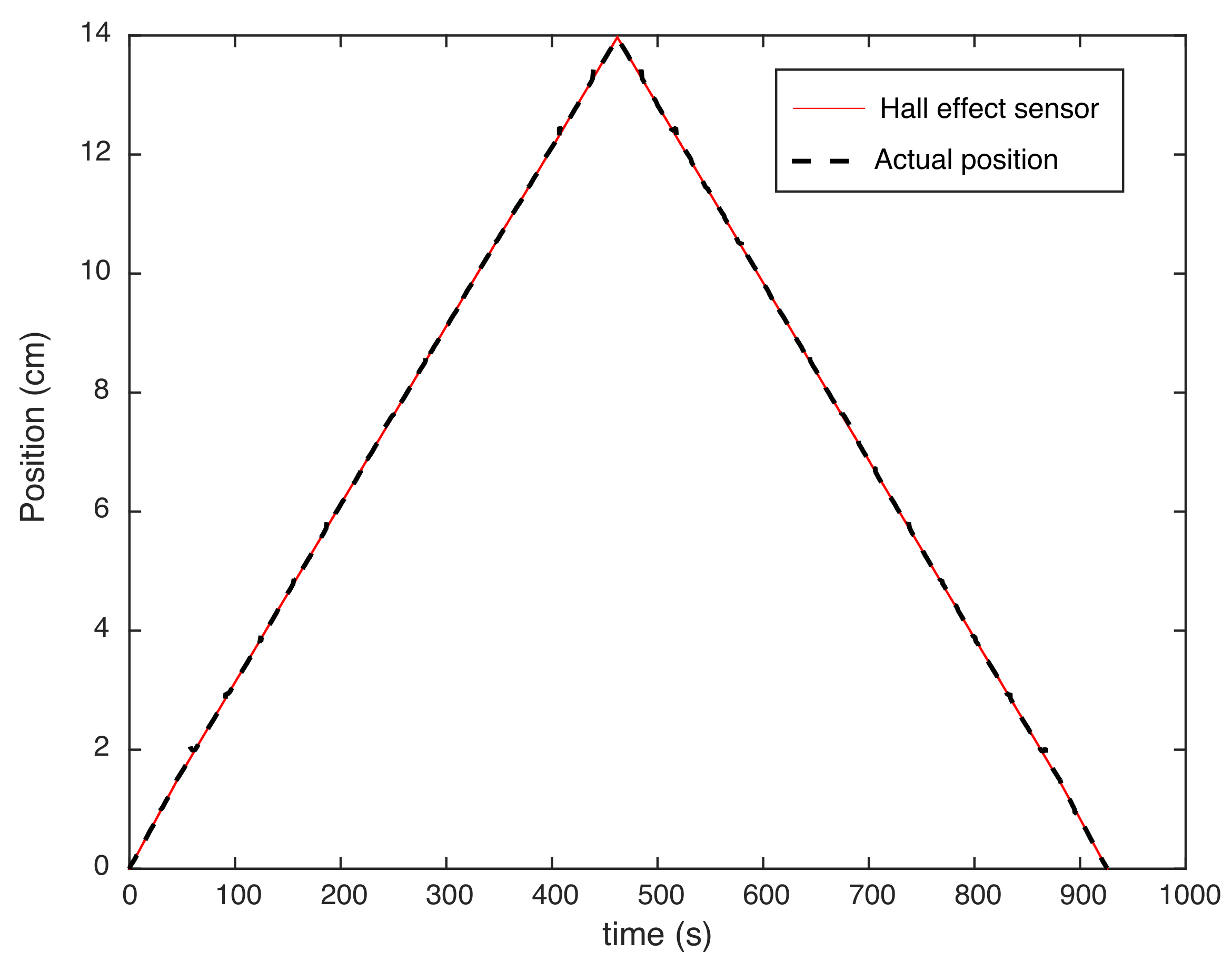
The position of the piston was obtained by using Hall effect sensors that measured the magnetic intensity of the neodymium magnet in the piston head. The magnetic intensity was measured using an array of Honeywell SS49E linear Hall effect sensors, arranged in sectional modules along the length of the pneumatic cylinder, as shown in Figure 1. The sensors were separated such that there was sufficient response overlap to allow absolute positioning of the piston-mounted neodymium magnet while minimizing the number of required individual Hall effect sensors. Each Hall effect sensor had a response length of cm and required at least cm of adjacent sensor overlap to calculate sufficient absolute sensor resolution. A total of 15 sensors was required to measure the piston position over the entire length of the piston. Figure 3 shows the raw voltage measured by the array of Hall effect sensors as the piston travels the full length. The Hall effect sensor array functioned using 15 micro-controller inputs, which were fed into an onboard 13-bit analog to digital converter. Using the response curve for each individual sensor, the responses of the individual sensors were compared to determine the active sensor and calculate the absolute piston position. The lead screw drive (see Section 2.2.4) was used to calibrate the position sensor. Figure 4 shows the final calibration fit for the position sensor. The sensors were soldered to machined PCB modules to minimize sensor cross-talk.
Force measurement was performed through the use of two Eyourlife pressure transducers, each of which was mounted on the two pressure supply ports on either side of the cylinder body. The sensors were calibrated to local atmospheric pressure (zero relative pressure) and maximum transducer pressure, verified by mechanical measurement (standard relative pressure gauge). Using the pressure measurements ( and ) and known cross-section area of the supply ports ( and ), the net force (F) was computed to be . The placement of transducers close to the cylinder requires long wires to carry measurement data to the micro-controllers. An alternate, simpler arrangement is to place transducer near the farther end of the pressure supply tubes, but this adds a time delay with the force measurement leading the actual force output at the piston. These time delays need to be accounted for in the control systems for stable control design [13].
2.2.2. Pneumatic Valve
Early work utilized multiple low-cost ARO P251SS-012-D 3-way/2-position solenoid valves. The solenoids were controlled through the use of a pulse width modulated (PWM) control signal at a frequency of 30 Hz to form a variable air flow rate into and out of the cylinders. Low level control with the setup was insufficient for precise positioning control at elevated operating pressures (greater than 40 psi) [14].
For all results reported here, we used an Enfield LS-V15s proportional flow valve (PFV) with a D1 PFV driver. The Enfield PFV was controlled through the use of a PWM control signal, but the modulation frequency was 32 kHz, thus allowing for rapid control.
2.2.3. Microcontroller
The control system utilized first an Arduino Mega 2560 (16-MHz clock speed) as the primary micro-controller, which was later upgraded to a Teensy 3.6 (180 MHz clock speed) due to the demand for increased processing speed. The microprocessor change required the inclusion of 5-volt/-volt level shifters due to differing multiprocessor voltage requirements for sensor inputs (Arduino Mega 2560 requires 5 V, while Teensy 3.6 requires V). Both micro-controllers feature similar programmatic operation, utilizing a linear operational program (no multithreading). Without multithreading, the program cycle time was highly dependent on individual functions, providing an inconsistent cycle time. This error was greatly reduced by moving to the faster Teensy, with the average cycle time being reduced from ms with the Arduino Mega 2560 to ms with the Teensy 3.6. The Teensy 3.6 was capable of handling all functions including piston position computation, controller implementation, external positioning (lead-screw) drive and data collection (via serial to an attached desktop computer).
2.2.4. Lead-Screw Linear Drive
A lead-screw-driven linear drive (Konmison SFU1605) was utilized to position the piston of the pneumatic cylinder during the force control and impedance control testing phases (see Figure 2b). It was also used to establish a positional base line during calibration of the Hall effect sensor array. Control of the SFU1605 was performed by the Teensy 3.6 through the use of the AccelStepper program library [15].
2.3. Control System
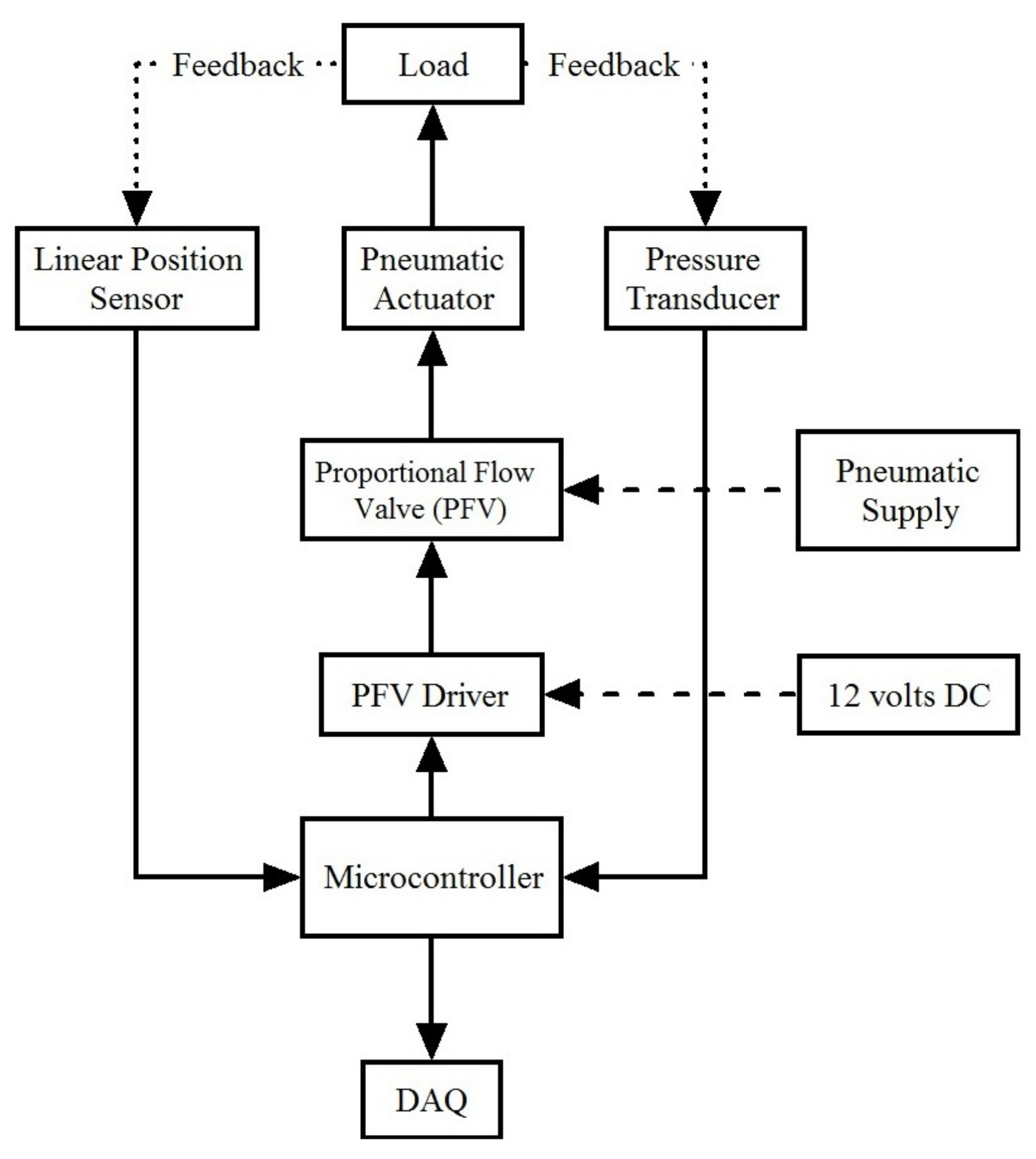
Figure 5 shows a block diagram of the control system. At the heart of the control system was the micro-controller. The micro-controller sends a voltage signal to the proportional flow valve driver (PFV) (D1 valve driver from Enfield Technologies). The PFV driver controlled the compressed air from the pneumatic supply system through a valve (LS-V15s, proportional pneumatic valve Enfield Technologies). The PFV moved the piston of the pneumatic actuator, which in turn moved the load. The pneumatic actuator had a custom-built position sensor based on Hall effect sensing and commercial pressure transducers that were calibrated to read the force. Both sensors were connected to the micro-controller to read the data. The Parallax PLX-DAQ software suite was used to log and save data for post-processing. The DAQ operated at 128 KBs.
The testing programs were designed to perform operations common to commercially produced pneumatic actuators, specifically position control, force control and impedance control. The position control program operated with the specific goal of bringing the cylinder piston to a defined position and maintaining it under the effect of external forces. The force control program operated with the specific goal of maintaining a specified net cylinder force relative to the cylinder body as the piston position was externally manipulated. The impedance control program was designed to be an extension of the force control program, utilizing the calculated cylinder forces and measured position to attempt to maintain a specified impedance as the piston was externally manipulated. As the impedance control was based on simple spring impedance, as the displacement approached a zero position, the output approached infinity. Therefore, a spring preload of one inch was instituted so that a zero displacement position would not grow abnormally high. This had the inherent effect of increasing the required supply pressure for a given target impedance, so care had to be taken to not designate a target impedance beyond the supply pressures that the thermoplastic cylinder was capable of withstanding.
The actuator was demonstrated on test cases using a set-point control based on the standard proportional and integral (PI) controller given by:
where , are constants for proportional and integral control, respectively, V is the voltage to the PFV, X is the quantity that needs to be regulated (e.g., position, force or impedance) and is the reference value. The gains were tuned manually: the proportional constant aggressively tuned to allow fast response, and the integral constant was used to bring the output to the reference value and to have negligible steady state error.
3. Results
3.1. Position Control
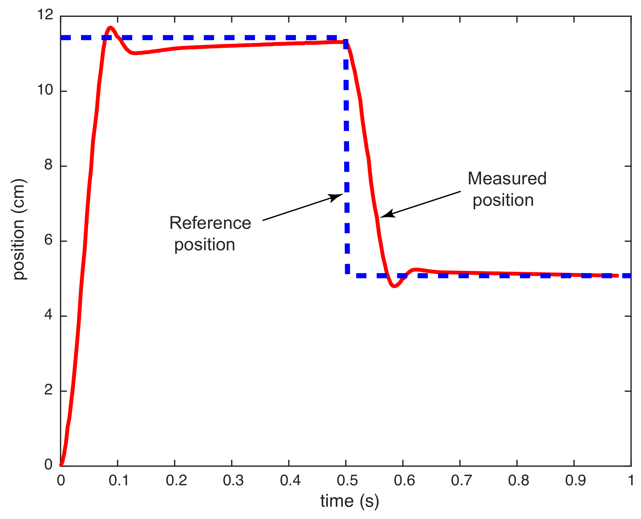
Figure 6 shows the results for position control. The position control test was performed with a regulated 25 psig supply pressure. The reference positions were two step inputs of amplitude cm and cm, each for s. The rise time was 50 ms. However, this does not include a delay time or time between initiation of the step command and first motion of 25 ms. The settling time was about 100 ms. The overshoot and steady state error were negligible.
This delay time was significant, about 50% of the rise time. The delay time was dependent on the design of the pneumatic system. It is the time needed for the compressed air to fill the empty space (air lines, fittings, etc.) passing through the PFV before the piston was able to reach the minimum pressure required for motion. The delay time may be minimized by reducing the lengths of the air flow paths between the control valve and the cylinder, by reducing the size of the empty cavities found on either side of the piston, by using either valves capable of a larger flow rate or by using a control system that offers a higher response. However, the latter changes could increase the speed of the piston substantially, leading to overshooting; hence, careful design of the controller is needed to have reasonable response characteristics. Furthermore, reductions in this delay can be realized by reducing the radial compression of the piston sealing mechanism in order to reduce the required minimum pressure to overcome piston friction, but care must be taken, or leakage will occur past the piston seal.
3.2. Force Control
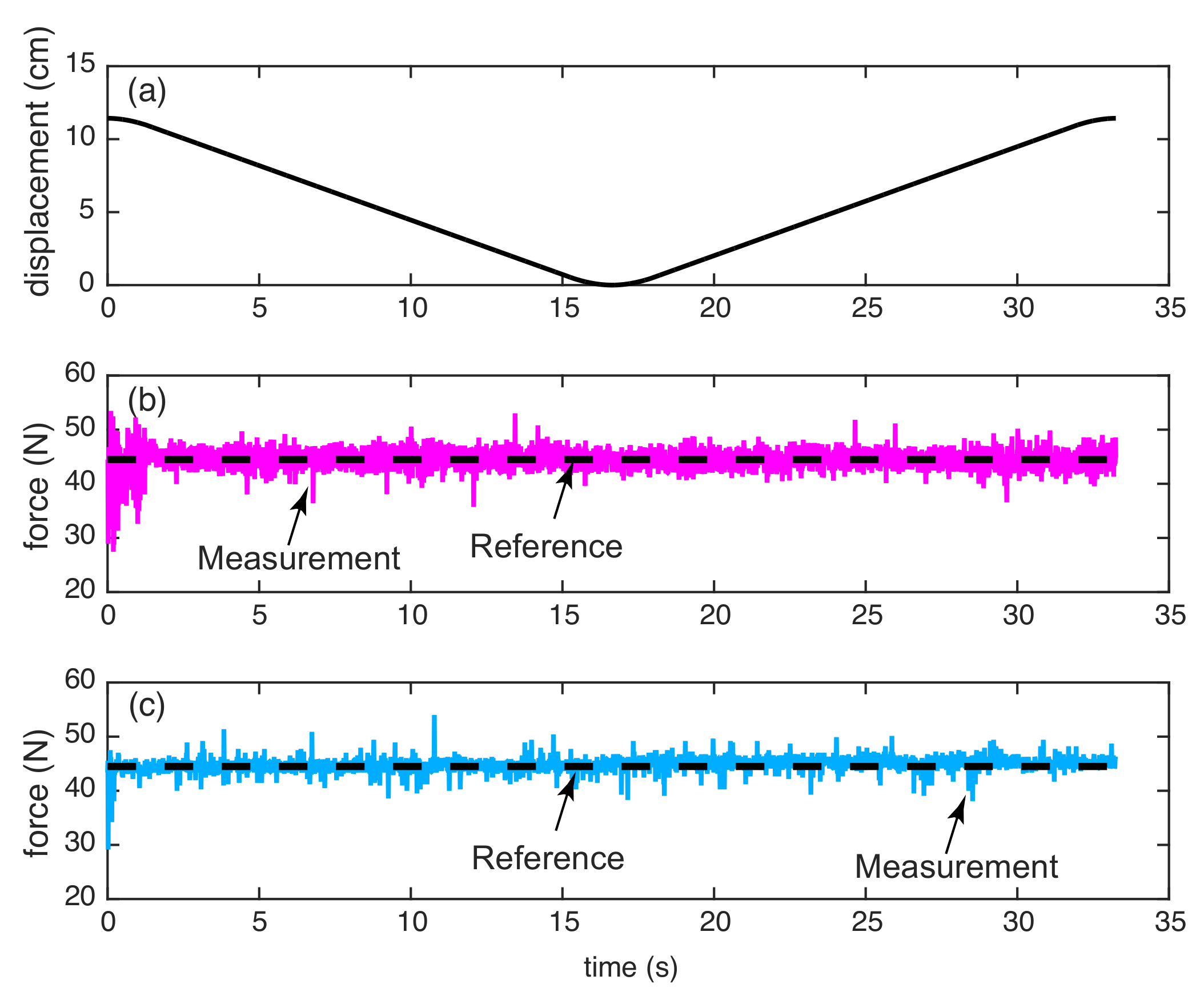
Figure 7 shows results for force control using the pneumatic actuator. The force control test was performed with a regulated 40 psig ( kN/m) supply pressure. The linear drive was placed in series with the pneumatic actuator such that the linear drive could exert a force on the piston of the pneumatic actuator as shown in Figure 2b. The objective was to maintain a constant compressive force of N while moving the linear actuator at a constant speed back and forth as shown in Figure 7a. An external linear drive coupled to the piston of the 3D-printed actuator imposes a constant speed on the device. The constant speed test is done to demonstrate that the 3D-printed actuator is able to maintain constant force throughout its travel distance. The force control was achieved using feedback from the force measured from the pressure sensors. Figure 7b shows the force as measured by the pressure sensors in the pneumatic chambers, and Figure 7c indicates force as measured by a strain gauge mounted on the output shaft. Note that Figure 7b is the force measured before the output shaft, and Figure 7c is at the output shaft. The two measurements should be the same except when there is measurable sliding friction. In such a case, the output force (strain gauge measurement) will be less than the input force (force measured in the pneumatic chambers). The average force values were N and N for the pressure transducer-based force and the strain gauge-based force, respectively.
The response shows initial spikes in the force measured by the pressure transducers (Figure 7b) around (where t is the time in second). Initially, the micro-controller was in the reset state. This causes a zero voltage input to the PFV, which corresponds to a full flow state. Thus, the piston was subjected to supply pressure. This increases the force leading to spike, and it takes a few more spikes before the micro-controller was able to regulate the force. At s, the linear slide reverses direction. The average force measured by the pressure sensor was unchanged. However, the average force values measured by the strain gauge were lower by an average of N, although this was not readily observable from the above plots. This was due to friction at the piston-cylinder interface, which shows up on the strain gauge reading, as it was mounted at the output shaft.
3.3. Impedance Control
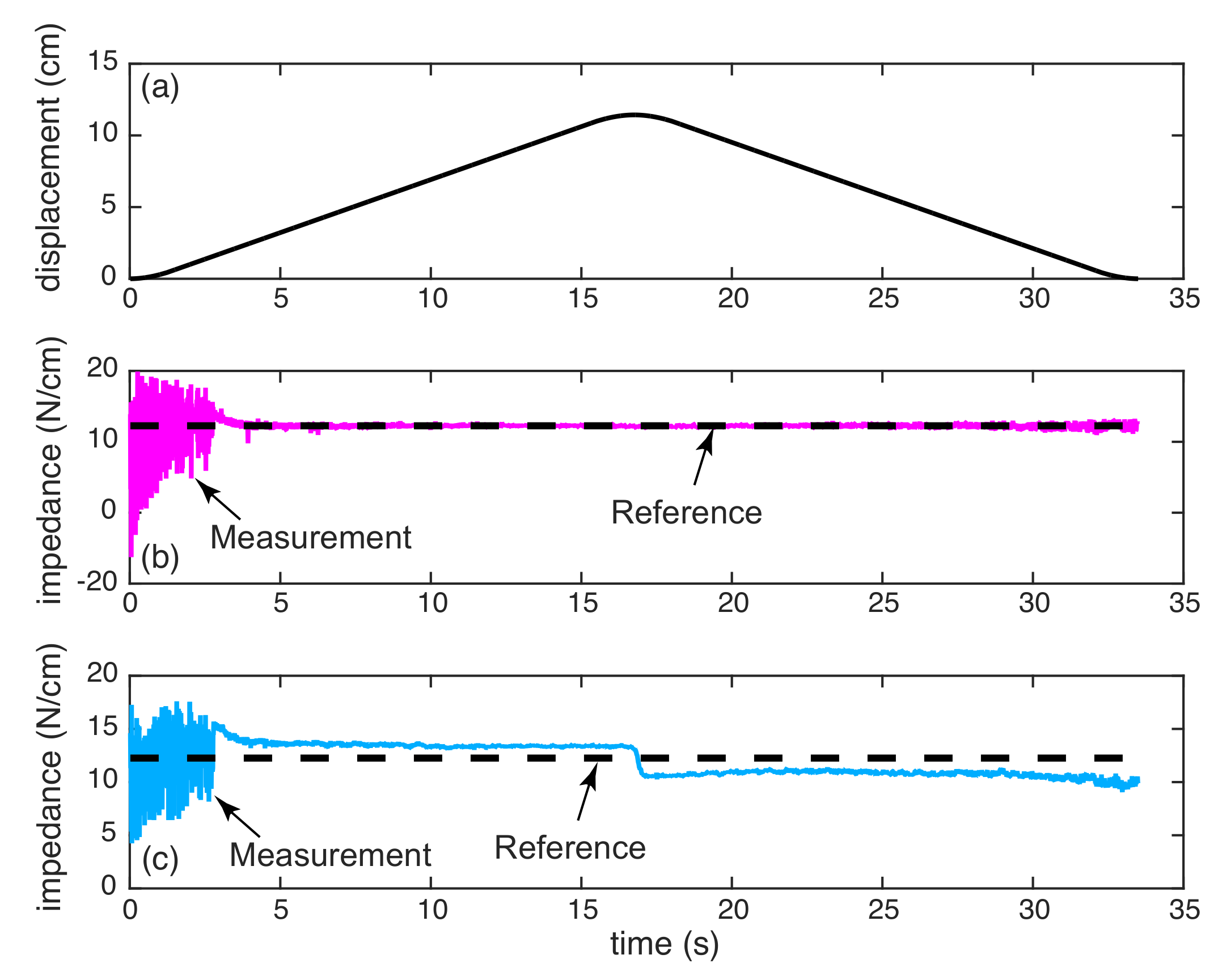
We define impedance control as being able to control the ratio of the force to the displacement to a prescribed value. Figure 8 shows results for impedance control using the pneumatic actuator. Impedance is defined as the ratio of the force to the displacement. The impedance control test was performed with a regulated 40-psig ( kN/m) supply pressure. Like the force control experiment, the linear drive was placed in series with the pneumatic actuator and moved at a uniform rate as shown in Figure 8a. The objective was to maintain N/cm (a constant value). The position was measured using the Hall effect sensors, and the force was measured using the pressure sensors. These sensors values were used to compute the measured impedance. As seen from Figure 8b, the measured impedance follows the desired impedance (shown as a black dashed horizontal line). The average impedance for the plot was N/cm. We also estimated the impedance using the force measurement from the strain gauge in combination with the position from Hall effect sensors. The impedance is shown in Figure 8c. The average impedance during increasing linear drive movement () was N/cm and during decreasing linear drive movement () was N/cm. The difference in impedances in these plots was due to a combination of friction and stick-slip displacement, as discussed in the next paragraph.
The impedance control test possesses some particularly interesting artifacts from a control standpoint. First, in the initial time period of the plot, , the response shows spikes. This was due to a combination of effects; specifically, it was due to the PFV starting movement from a full open position as previously described, as well as the displacement and pressure transducer values were sufficiently small and were close to the noise levels in the measurements. Thus, measured impedance was noisy, and the use of high gains amplified the noise and showed up as spikes in the plot. However, as the displacement and forces increased (the sled moves from the initial position), the noise was no longer an issue, and tracking was easier. This effect can be alleviated by increasing the accuracy of the utilized pressure transducers or selecting a PFV with higher resolution for a lower volumetric flow (overall response would suffer due to a reduced maximum flow rate). The second point of interest was that the measured impedance using the strain gauge was different as the linear drive reversed direction at s. There are two factors that contribute to this: (1) the sliding friction force, which shows up in the strain gauge reading; and (2) the displacement error at the onset due to the sliding friction force. The latter was caused due stick-slip behavior that occurred when the piston head changed direction. It was much easier to control the actuator at slow speeds using the force measurement from pressure transducers, as there was no friction to be accounted for, but harder using the strain gauge, as friction can lead to nonlinearities that may degrade performance.
4. Discussion
We have presented the design and construction of a 3D-printed linear pneumatic actuator. The cylinder, sensor cover, end caps and piston head were all 3D printed using PolyLactic Acid (PLA), a thermoplastic, while the piston was a stainless steel rod for strength. A magnet embedded in the piston head produces a magnetic field that was measured by Hall effect sensors embedded on the outside of the cylinder to measure the position and two pressure transducers placed in the two chambers of the cylinder where the pneumatic tube meets the cylinder to measure the force by suitable calibration. The actuator was controlled using an off-the-shelf high performance proportional flow valve. The utility of the actuator was demonstrated by performing position control, force control and impedance (or stiffness) control experiments. Our work is novel as it demonstrates for the first time the possibility of creating a linear pneumatic actuator comparable to an industrial-grade pneumatic actuator in terms of size, stroke length and input pressure by 3D printing using PLA (a thermoplastic).
The design of the 3D-printed cylinder requires a few considerations. As an FDM 3D printer functions on a layer-by-layer basis (the current layer is adhered to the subsequent layer), the material bonds were weakest in the direction perpendicular (z-axis) to the printing plane (x-y axis). The cylinder was 3D printed such that the z-axis of the printer aligned with the length of the cylinder. Due to this print configuration, the cylinder was weakest for forces imparted along the piston travel direction. This caused the 3D-printed cylinder to be particularly susceptible to high magnitude forces, particularly the forces that arise from unrestrained travel within the cylinder, which results in a high magnitude impact with the 3D-printed cylinder body. Thus, the 3D-printed cylinder should be designed so that the actuated movement range terminates before the piston impacts with either end of the 3D-printed cylinder. Another issue was the limited resolution of our hobby-grade 3D printer that led to a rough surface finish and pores in the cylinder. This was an issue, as it would lead to higher friction and air leakage. A post-processing procedure we employed involving sanding the inner surface using a hand-drill was able to improve the surface finish and close the pores. Another technique we have used in the past was chemical post-processing. This involved dipping the 3D-printed part in acetone, and this worked only for certain plastics, namely acrylonitrile butadiene styrene also (ABS), that chemically react with acetone.
The seal-cylinder interface was where the actual movement occurs. This interface can get heated up quickly, and maintaining a sufficient flow rate and lubrication was important. The amount of allowable heat generation will vary according to the dimensions of the specific cylinder, but the interior surface temperature of the bore should not exceed 100 degrees Fahrenheit, otherwise plastic deformation of the cylinder could occur, possibly allowing the cylinder to deform to the extent that leakage past the piston seal may occur, rendering the pneumatic cylinder inoperable. Another idea to reduce heating is to use a rolling diaphragm to seal the pneumatic cylinder, and this is advantageous because rolling friction produces less heat than sliding friction due to the lower contact area in rolling movements [16].
The total cost of the custom-made pneumatic actuator including the position sensing, but excluding the proportional control valve and micro-controller was about USD 90. A comparable commercially available pneumatic actuator, the Bimba PFCNL-09 [1], has a list price for the base cylinder/position sensing apparatus of about USD 580, about -times our actuator. Both actuators have comparable weight ( kg for Bimba and kg in our 3D-printed actuator). Bimba operates at about 70–80 psig, but we have only tested ours up to 40 psig in dynamic loading and up to 150 psig in static loading without failure. Furthermore, our actuator has an accuracy of mm and a linearity of 3%, which were lower than those of Bimba (accuracy of mm and linearity of 1%). A major cost for our actuator was the off-the-shelf pneumatic valves and drives (Enfield Technologies) that cost about United States Dollar (USD) $700. These were necessary to achieve high fidelity position and force control. In our previous work, we created a custom valve driver using a solenoid driven by pulse width modulation costing about USD 50, but it had a limited bandwidth of 30 Hz [14].
The force control in this paper is called collocated control. In collocated control, the actuator and sensor are placed at the same location. In our case, force was measured using pressure sensors placed in the pneumatic chambers and controlled using air flow from valves. Thus, the force was measured before the output shaft. On the other hand, we also measured the force at the output shaft using a strain gauge, but this force measurement was not used for force control. The output shaft forces are different from forces measured before the output shaft because of friction and air compressibility. Controlling the output shaft force using compressed air in the chambers is called non-collocated control because the actuator and sensor are placed at different locations. We did not attempt non-collocated control here, but it is more difficult because one needs to account for additional dynamics between the actuator and sensor. Careful design of non-collocated control system is desirable to prevent system instabilities [17].
We investigated the use of resistive and capacitive sensing for position measurement. For resistive sensing, we attempted to 3D print a conductive plastic along the inner surface of the cylinder. However, we had difficulty in printing a smooth layer of conductive filament and had to abandon the method. For capacitive sensing, a suitably conductive material was placed along the length of the cylinder as concentric plates. One plate serves as a reference, while the other moves with the piston, causing a varying amount of capacitance between the concentric plates. This is a non-contact measurement system, but had poor accuracy due to external interferences and requires investigating shielding techniques (e.g., enveloping the cylinder in a system ground plane, for example). Another issue we found was that with capacitive sensing, there was a loss of measurements close to the ends of the cylinder. Ultimately, we found that magnet-based sensing using a Hall effect sensor worked well for our actuator.
5. Conclusions
Our conclusion is that it is possible to use 3D printing to create a pneumatic actuator that is comparable to commercial actuators in terms of strength and performance, but at a fraction of the cost. Several key strategies were discussed and included: (1) the use of metallic inserts in high stress areas; (2) a sanding procedure along the inner surface for a smooth finish; (3) piston head design and seal placement for leak-proof motion; and (4) appropriate sensor choice and placement for position and force control. This research could potentially open new techniques for creating less expensive, customizable and capable actuators by harnessing 3D printing technology.
However, our work also has several limitations. The cylinder requires extensive post-processing, which was critical for a good surface finish and closing the pores. This issue may be resolved by using higher resolution printers (e.g., industrial-grade printers), but some post-processing might still be needed for a smooth finish. Although we used 3D printing with the intent of having a lighter actuator than that commercially available, our 3D-printed actuator had a similar weight as that of an industrial-grade actuator to which we compared our actuator. We could have reduced the weight by replacing the stainless steel rod with aluminum and further reducing the cylinder wall thickness. The latter would result in reduced cylinder strength and durability. Although our 3D-printed actuator was almost six-times less expensive than a commercial actuator of the same size, the use of an off-the-shelf flow rate valve increases the cost of the actuator substantially. Though we have tried creating our own valve using solenoid and pulse width modulation, the low bandwidth meant that we were unable to have high fidelity control. We have tried a naive hand-tuned proportional-integral controller, and better tracking and performance may be achieved using a model-based controller, but this would necessitate identification of the system. Finally, the availability of multi-material printers that can print multiple materials (e.g., metals, plastic) simultaneously including sensors would make the actuator truly monolithic besides providing the great customizability of 3D printing.
Author Contributions
J.K. designed the hardware and did all the experiments. J.K. and P.B. wrote the paper together.
Acknowledgments
This work was funded by the University of Texas at San Antonio, Office of the Vice President for Research.
Conflicts of Interest
The authors declare no conflict of interest.
References
- Bimba. Position Control System Products. Available online: https://www.bimba.com/sites/default/files/Library%20Archives/Catalogs/Bimba/Position_Control_System_Products.pdf (accessed on 1 April 2018).
- Reininger, T.; Welker, F.; Von Zeppelin, M. Sensors in position control applications for industrial automation. Sens. Actuators A Phys. 2006, 129, 270–274. [Google Scholar] [CrossRef]
- Vyhnanek, J.; Ripka, P.; Chirtsov, A. Linear Position Sensing through Conductive Wall without Permanent Magnet. Proceedings 2017, 1, 390. [Google Scholar] [CrossRef]
- Atkeson, C.G.; Hale, J.G.; Pollick, F.; Riley, M.; Kotosaka, S.; Schaal, S.; Shibata, T.; Tevatia, G.; Ude, A.; Vijayakumar, S.; et al. Using humanoid robots to study human behavior. IEEE Intell. Syst. Their Appl. 2000, 15, 46–56. [Google Scholar] [CrossRef]
- Ben-Dov, D.; Salcudean, S.E. A force-controlled pneumatic actuator. IEEE Trans. Robot. Autom. 1995, 11, 906–911. [Google Scholar] [CrossRef]
- Tassa, Y.; Erez, T.; Todorov, E. Synthesis and stabilization of complex behaviors through online trajectory optimization. In Proceedings of the 2012 IEEE/RSJ International Conference on Intelligent Robots and Systems (IROS), Vilamoura, Portugal, 7–12 October 2012; IEEE: Piscataway, NJ, USA, 2012; pp. 4906–4913. [Google Scholar]
- Peele, B.N.; Wallin, T.J.; Zhao, H.; Shepherd, R.F. 3D printing antagonistic systems of artificial muscle using projection stereolithography. Bioinspir. Biomim. 2015, 10, 055003. [Google Scholar] [CrossRef] [PubMed]
- MacCurdy, R.; Katzschmann, R.; Kim, Y.; Rus, D. Printable hydraulics: A method for fabricating robots by 3D co-printing solids and liquids. In Proceedings of the 2016 IEEE International Conference on Robotics and Automation (ICRA), Stockholm, Sweden, 16–21 May 2016; IEEE: Piscataway, NJ, USA, 2016; pp. 3878–3885. [Google Scholar]
- Wei, Y.; Chen, Y.; Yang, Y.; Li, Y. Novel design and 3-D printing of nonassembly controllable pneumatic robots. IEEE/ASME Trans. Mechatron. 2016, 21, 649–659. [Google Scholar] [CrossRef]
- De Laurentis, K.J.; Mavroidis, C.; Kong, F.F. Rapid robot reproduction. IEEE Robot. Autom. Mag. 2004, 11, 86–92. [Google Scholar] [CrossRef]
- Yang, Y.; Chen, Y. Innovative Design of Embedded Pressure and Position Sensors for Soft Actuators. IEEE Robot. Autom. Lett. 2018, 3, 656–663. [Google Scholar] [CrossRef]
- Nall, C.; Bhounsule, P.A. A Miniature 3D Printed On-Off Linear Pneumatic Actuator with Application for Legged Robots. IEEE/ASME Trans. Mechatron. 2018. submitted. [Google Scholar]
- Ogata, K. Modern Control Engineering; Prentice Hall India: Delhi, India, 2002; Volume 4. [Google Scholar]
- Krause, J.; Bhounsule, P. Variable Position and Force Control of a Pneumatically Actuated Knee Joint. In Proceedings of the ASME 2017 International Design Engineering Technical Conferences and Computers and Information in Engineering Conference, Cleveland, OH, USA, 6–9 August 2017; American Society of Mechanical Engineers: New York, NY, USA, 2017; p. V05AT08A059. [Google Scholar]
- AirSpayce. AccelStepper Library for Arduino. Available online: http://www.airspayce.com/mikem/arduino/AccelStepper/ (accessed on 1 April 2018).
- Whitney, J.P.; Glisson, M.F.; Brockmeyer, E.L.; Hodgins, J.K. A low-friction passive fluid transmission and fluid-tendon soft actuator. In Proceedings of the 2014 IEEE/RSJ International Conference on Intelligent Robots and Systems (IROS 2014), Chicago, IL, USA, 14–18 September 2014; IEEE: Piscataway, NJ, USA, 2014; pp. 2801–2808. [Google Scholar]
- Eppinger, S.D.; Seering, W.P. Three dynamic problems in robot force control. IEEE Trans. Robot. Autom. 1989, 8, 392–397. [Google Scholar]
Figure 1.
Actuator: (a) exploded view; (b) assembled view; and (c) final prototype.

Figure 2.
Experimental setup: (a) actuator connected to the microcontroller and pneumatic tubes; and (b) actuator applying force against the linear drive for the force and impedance control tests.
Figure 2.
Experimental setup: (a) actuator connected to the microcontroller and pneumatic tubes; and (b) actuator applying force against the linear drive for the force and impedance control tests.

Figure 3.
Voltage data from the Hall effect sensor as the piston slides along the length of the cylinder. Response from only five Hall effect sensors out of thirteen are shown.
Figure 3.
Voltage data from the Hall effect sensor as the piston slides along the length of the cylinder. Response from only five Hall effect sensors out of thirteen are shown.

Figure 4.
Measurements from the thirteen sensors are combined to give the absolute position of the piston. Data taken as the piston moves from minimum extension to maximum and back versus time. The red solid line shows the measurement from Hall effect sensors, and the black thick dashed line indicates independent measurement using a linear drive.

Figure 5.
A block diagram showing the various components of the experimental setup for position, force and impedance control.
Figure 5.
A block diagram showing the various components of the experimental setup for position, force and impedance control.

Figure 6.
Results for position control. The input was a reference position with steps at s and s.

Figure 7.
Results for force control: (a) lead screw movement; (b) force measured using pressure sensors in the pneumatic chambers (before output shaft); and (c) force measured using the strain gauge at the output shaft.
Figure 7.
Results for force control: (a) lead screw movement; (b) force measured using pressure sensors in the pneumatic chambers (before output shaft); and (c) force measured using the strain gauge at the output shaft.

Figure 8.
Results for impedance control: (a) lead screw movement; (b) impedance values with force measured using pressure sensors in the pneumatic chambers (before output shaft); and (c) impedance values with force measured using the strain gauge at the output shaft.
Figure 8.
Results for impedance control: (a) lead screw movement; (b) impedance values with force measured using pressure sensors in the pneumatic chambers (before output shaft); and (c) impedance values with force measured using the strain gauge at the output shaft.

© 2018 by the authors. Licensee MDPI, Basel, Switzerland. This article is an open access article distributed under the terms and conditions of the Creative Commons Attribution (CC BY) license (http://creativecommons.org/licenses/by/4.0/).
Share and Cite
MDPI and ACS Style
Krause, J.; Bhounsule, P. A 3D Printed Linear Pneumatic Actuator for Position, Force and Impedance Control. Actuators 2018, 7, 24. https://doi.org/10.3390/act7020024
AMA Style
Krause J, Bhounsule P. A 3D Printed Linear Pneumatic Actuator for Position, Force and Impedance Control. Actuators. 2018; 7(2):24. https://doi.org/10.3390/act7020024
Chicago/Turabian StyleKrause, Jeremy, and Pranav Bhounsule. 2018. "A 3D Printed Linear Pneumatic Actuator for Position, Force and Impedance Control" Actuators 7, no. 2: 24. https://doi.org/10.3390/act7020024
Note that from the first issue of 2016, this journal uses article numbers instead of page numbers. See further details here.