Polymer Microgripper with Autofocusing and Visual Tracking Operations to Grip Particle Moving in Liquid

Department of Mechanical Engineering, National Cheng Kung University, Tainan 70101, Taiwan
*
Author to whom correspondence should be addressed.
Actuators 2018, 7(2), 27; https://doi.org/10.3390/act7020027
Submission received: 21 May 2018
/
Revised: 7 June 2018
/
Accepted: 7 June 2018
/
Published: 11 June 2018
(This article belongs to the Special Issue Micromanipulation)
Abstract
:A visual-servo automatic micromanipulating system was developed and tested for gripping the moving microparticle suspended in liquid well. An innovative design of microgripper integrated with flexible arms was utilized to constrain particles in a moving work space. A novel focus function by non-normalized wavelet entropy was proposed and utilized to estimate the depth for the alignment of microgripper tips and moving particle in the same focus plane. An enhanced tracking algorithm, which is based on Polar Coordinate System Similarity, incorporated with template matching, edge detection method, and circular Hough Transform, was implemented. Experimental tests of the manipulation processes from moving gripper to tracking, gripping, transporting, and releasing 30–50 μm Polystyrene particle in 25 °C water were carried out.
1. Introduction
The manipulation of micro objects in liquid environment has become a great challenge in biotechnical engineering [1]. Micromanipulation of artificial particle or biological cell is a crucial technology for acquiring the geometrical, mechanical, electrical and/or chemical properties of micro objects. In addition, micromanipulation technique can be employed for analyzing the interactions between artificial particle and biological object. Micromanipulation in general requires accurate and precise position and/or force operations in holding, picking, placing, pulling, pushing, cutting, and indenting biotechnical micro objects. Regarding biotechnical manipulation, various approaches have been implemented: optic and electric micromanipulation, magnetic micromanipulation, microelectromechanical systems (MEMS) and mechanical micromanipulation [2]. Early research on utilizing micro end effector for biotechnical manipulation was contributed by Carrozza et al. [3], Ok et al. [4], and Arai et al. [5]. For manipulating moving bioparticle or cell, a non-damage holding technique is generally required before proceeding with further micro operation. In the conventional micromanipulation, a pipette is utilized carefully to hold the micro objects in liquid. In a more recent approach, acoustic pressure field is proposed to preposition micro particles in liquid prior to manipulation by utilizing MEMS gripper [6]. To work with biological samples, such as living cells, it must be possible to immerse the end effector tips into liquids. The micromanipulation technology with device dimensions and material properties compatible to biological cell finds important applications in the biomedical manipulation [7,8]. In considering the different requirements of manipulating micro particles in liquid environment, several mechanical microgrippers have been developed for these applications [1,3,6,7,8,9,10,11,12,13,14,15,16,17,18]. Regarding the manipulation of micro particles in liquid environment, the research on gripping stationary artificial particle [1,3,6,7,10,11,12,15] and living cell [3,6,9,13,14,16] has been reported. For the in vivo operations at smaller size scales, untethered microgrippers that can be navigated to grasp living cell or tissue have been reviewed recently [19,20]. When the micro living cell is moving in liquid, the manipulation technique to hold the cell without causing damage needs further development.
Microscopic autofocus operation is an important technique utilized in the detection, tracking, and grasping of micro objects [21,22,23,24]. In gripping objects, it is actually one of the most essential techniques to ensure the successful operation. In the literature, the performance of focus functions has been widely investigated and compared [25,26,27,28,29,30,31]. Based on the comparison results of focusing different types of images, in general, recommended effective focus functions include energy Laplace [25], normalized variance [30], wavelet-based measure [31], and autocorrelation for fluorescence microscopy [29]. Regarding the technique for tracking particle, it can be traced back to the Particle Tracking Velocimetry (PTV). In the literature, there are several tracking algorithms for PTV ([32], and references therein). In implementing the digital PTV, temporal tracking scheme of matching the same particles in the consecutive time step is the core technique of each PTV algorithm. A tracking algorithm, which is insensitive to experimental parameters and applied to flows subjected to drift and diffusion, is considered in this paper. Although the performance of focusing functions has been widely tested in the aforementioned literature, it is noted that the focusing operation has not been tested by integrating them with visual tracking and grasping operation. Particularly, the automatic alignment of microgripper tips with moving micro particle in the same focus plane is the most essential test to ensure successful gripping operation.
In this paper, innovative design of microgripper, novel focus function, and enhanced tracking algorithm are proposed for gripping micro particle moving in liquid. After the Introduction, Section 2 describes the system design and installation of the micro manipulation system. An innovative design of microgripper integrated with flexible arms is utilized to constrain particles in a moving work space. Section 3 is dedicated to the innovative autofocus function which is utilized to estimate the depth for the alignment of microgripper tips and moving particle in the same focus plane. Section 4 gives an enhanced two-frame scheme for tracking particle under drift and diffusion flow. Section 5 provides experimental test and record of gripping microparticle. Operational processes from moving gripper to tracking, gripping, transporting, and releasing micro particle were carried out in experimental tests. In Section 6, we summarize the present innovative approach of utilizing microgripper to grip moving particle.
2. System Design and Installation
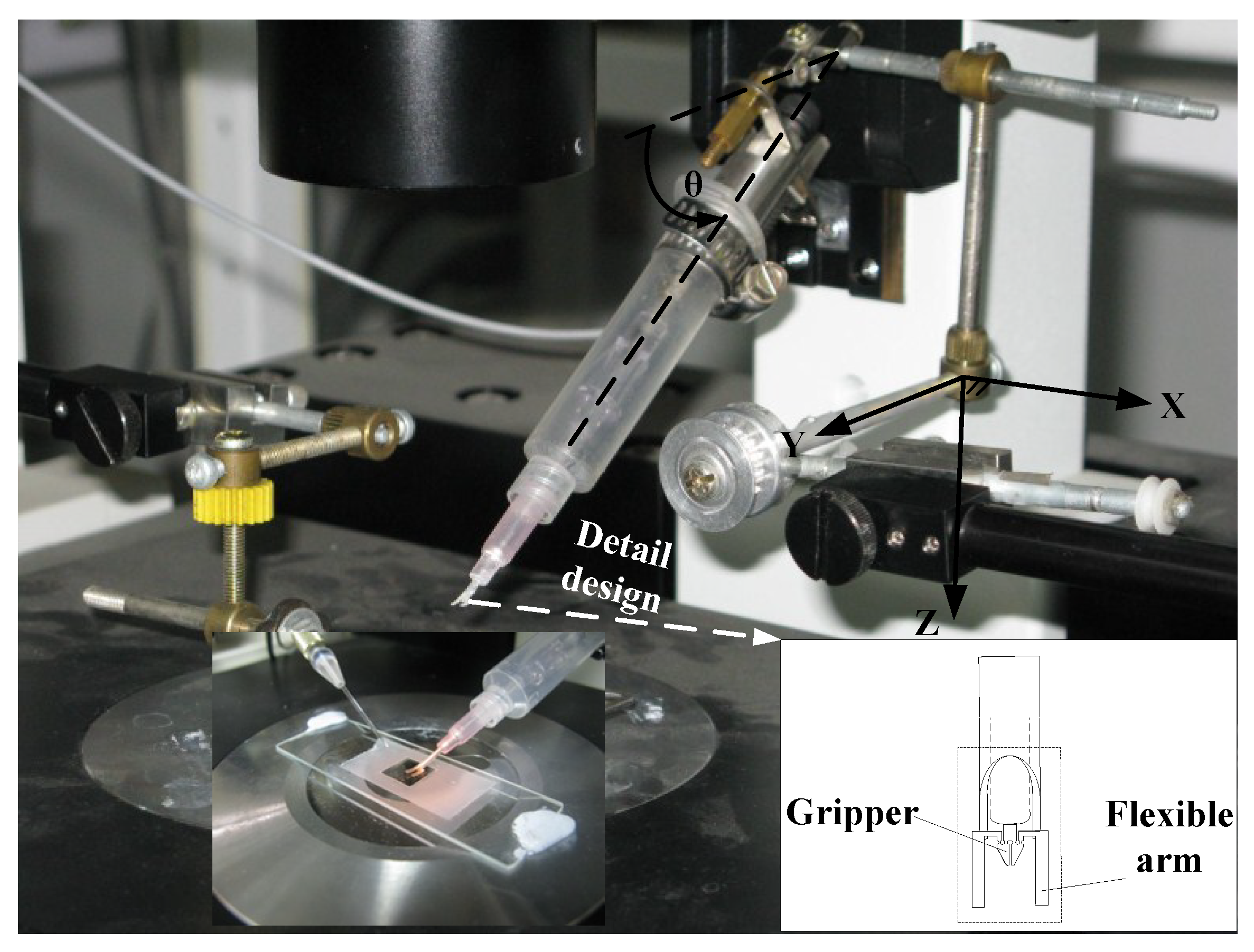
A micromanipulation system installed to realize grasping micro particle with autofocusing and automatic tracking operations is shown in Figure 1. The micromanipulation system consists of Micro Gripper System, Moving Manipulator System, Object Stage, and Autofocusing Stage. The detail design of the four subsystems is described in the following sections.
2.1. Micro Gripper System and Moving Manipulator System
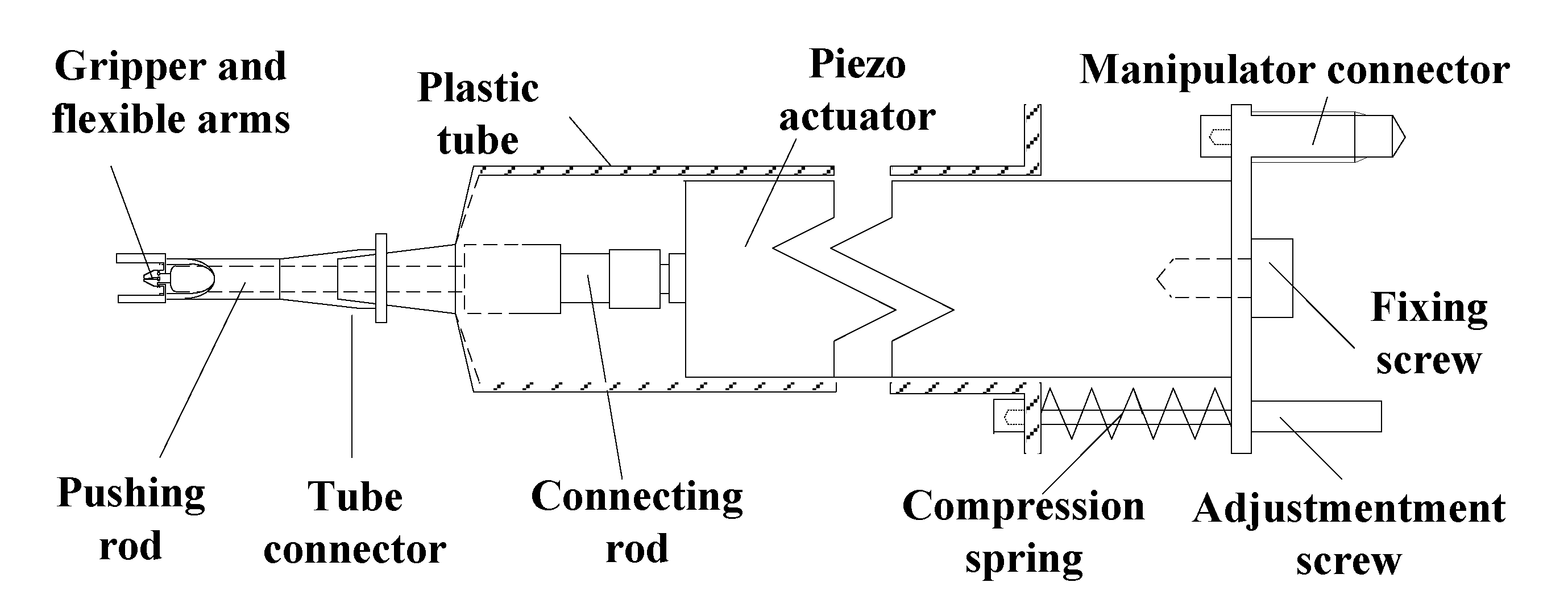
Micro Gripper System was installed on the Moving Manipulator System. The Moving Manipulator System, MMS-77 from Shimadzu (Kyoto, Japan), is an X-Y-Z stage with 0.1 μm resolution, 30 mm stroke for X and Y axes, and 15 mm stroke for Z axis. The maximum moving speed is 3 mm/s. The Micro Gripper System consists of Gripper and Actuator Mechanism as well as Gripper Controller. The Gripper and Actuator Mechanism include micro gripper and actuating mechanism, as shown in Figure 2. The micro gripper is fabricated by utilizing Excimer Laser, Exitech 2000 (Oxford, UK), with mask projection through 10× size reduction by an optical lens. The micro gripper is driven through a connecting rod by piezoelectric actuator, P-820.10. The design with pushing rod is to minimize the geometrical interference between the piezoelectric actuator and liquid well in gripping operation. By employing the present design, the Micro Gripper System is able to grip a micro particle with diameter around 20–90 μm by the input of 0–100 V from the Gripper Controller, PI (Physik Instrumente) E-503.00 (Munich, Germany).
The innovative micro gripper is made of PU (Polyurethane) film which is 200 μm in thickness. The Young’s modulus of PU is 76.4 MPa. The present gripper mechanism is similar to that of the SMA (Shape Memory Alloy) drive PU microgripper employed for gripping micro particle [33]. The mechanism of micro gripper is symmetric with respect to the gripper axis. The kinematic motion of one gripper tip can be modeled through a four-bar orthogonal double slider linkage with one slider along gripper axis as input. Regarding the gripping force, it depends on the geometrical and material property of micro object, gripper–object contact condition, as well as the holding and gripping displacement. When gripping a soft object with Young’s modulus less than that of the PU, the gripping force can be analyzed and calibrated in advance through controlling the input displacement. In the present innovative design, as shown in the bottom right corner of Figure 1, the design is to incorporate a pair of flexible arms which are fabricated and integrated on the outer right and left sides of gripper frame. The flexible arms are designed to provide important functions: visual contact probe, constraint of particle movement, and reference for focus plane. When the manipulator moves downward in Z direction, the flexible arms will first approach to touch the inner bottom of liquid container. Then, the continue motion of Moving Manipulator System will cause bending of the flexible arms. The bending flexible arms form a rectangular notch to constrain the fluid flow and trap moving particles. In addition, the reflected edge of bending flexible arms can be monitored through the vertical visual CCD (Charge Coupled Device) system to provide a reference focus plane for positioning the gripper tips and avoiding collision with bottom surface.
2.2. Object Platform
Object Platform is a platform to support particles and fluid container. The platform was installed on another MMS-77 from Shimadzu (Kyoto, Japan). The specifications of MMS-77 to support container are the same as those of MMS-77 employed for installing Micro Gripper System.
2.3. Autofocusing Stage
Autofocusing Stage includes illumination system, CCD visual system, Z-axis servo system, and autofocusing controller. The autofocusing system is implemented through Olympus IX71 (Tokyo, Japan) inverted microscope. With 4× object lens, the view range is 1592 × 1194 × 25 μm3. The stage is driven by stepping motor with 1.8 degree/step through a gear train of 4.54 ratio. The moving resolution of focusing stage in Z axis by stepping motor is 0.28 μm/degree. The detail components of the image-based Autofocusing Stage are shown in the block diagram of Figure 3. A functional block of the Procedure of autofocusing operation is implemented by PC (Personal computer). The image signal of moving Z position is sensed by CCD through microscope and image capture card. The focusing control through PC can be operated in open-loop or closed-loop mode. The closed-loop control is to realize the autofocusing operation with feedback image signal of moving Z position.
The synergetic operation of the four subsystems for automatic operation of focusing, tracking and grasping micro particle is implemented by utilizing C/C++ on a PC with Intel® Core™ 2 CPU. The Clock rate of CPU is 2.13 GHz. The human–machine control interface was implemented by employing Microsoft Foundation Classes. The communication between computer and the subsystems is through image capture card, Morphis (MOR/2VD/84) from Matrox (Quebec, Canada), AD/DA cards, PCI-1727U and PCI-1710HG from Advantech (Kaohsiung, Taiwan), and communication interface by RS-232.
3. Autofocusing Operations
A visual servo system with autofocusing operations is an important setup on gripping moving particle. The present image-based autofocusing operation is the first to focus the moving particle and gripper tips, respectively, by evaluating the autofocusing function at different in-focusing positions. Then, the in-focusing positions are utilized to estimate the depth for aligning the gripper tips with moving micro particle in the same focus plane.
Regarding the image-based autofocusing operation, the focus scheme involves searching strategy and evaluating focus measure to locate the focus position. The searching strategy usually includes Global search, Binary search, and Rule-based search [25,34,35]. The selection consideration of searching strategy depends on the searching range, speed, accuracy, and robustness. In the digital searching process, a discrete focus measure which obtains the maximum value in the focusing range is deemed as the best focused image. A discrete focus measure to be formulated is expected to have the properties of the unbiased distribution, clear single apex, high sensitivity, good anti-noise capability, and rapid computation.
In the past, many discrete focus functions have been proposed in the literature. By summing up the different classification of focus functions proposed by Groen et al. [27], Sun et al. [30], and Xie et al. [31], the discrete focus functions in general can be categorized as Derivative-based measure [36,37,38,39,40], Statistics-based measure [27,39,41,42], Histogram-based measure [28], Gray level magnitude-based measure [26,27,29], and Wavelet-based measure [31,43]. In the present focusing and gripping applications, a new focus measure was proposed and the focusing performance was tested and compared with the widely-used measures.
3.1. Wavelet-Entropy Focusing Function
In an image, the diversity of pixel grey level of a focused image is usually greater than that of a defocused one. From the viewpoint of information science, a focusing process can be considered as changes of distribution content of an image. Since an entropy function is a measure of diversity as information content, it may be selected and utilized as a focusing function. Firestone et al. (1991) [28] proposed a histogram-measure Shannon entropy, which is formulated by utilizing the probability of grey level occurred in an image, as a focusing function. The focusing performance of histogram-measure entropy had been tested and compared with other focusing functions. From various comparative studies, the performance of histogram-measure entropy is poor [30,31]. For defining a focus function, it may not be appropriate to formulate entropy through grey level in space domain.
Beyond the information viewpoint on focusing process, a focusing process can be considered as changes of spatial energy content of an image. Application of wavelet energy analysis for defining focus function was proposed by Xie et al. (2007) [31]. The formulation of focus function was to utilize spatial image energy through wavelet coefficients since the orthogonal discrete wavelet transform preserves the contents of image energy. When focusing the image, the energy of high frequency will increase while the energy of low frequency will decrease. In the comparison of four focus measures by Histogram Entropy, Energy Laplace, Normalized Variance, and Wavelet Algorithm, testing results revealed that Mw, which was formulated as a ratio between high frequency energy and low frequency energy, provided the best performance.
The present focusing operation involved two different scales of objects, gripper tips and micro particles, which is different from the aforementioned focusing images under tests. Considering this, a new measure to integrate both information and energy contents in an image may be better utilized for the present applications. First, the Shannon entropy function, which can measure the contents of average information of objects, may be eligible. In the entropy formulation, the discrete Shannon entropy is defined as [28]
where X is a random variable with n outcomes {xi: i = 1, …, n} and pi is the probability of outcome xi. Next, the probability distribution of signal energy relative to the total signal energy can be expressed:
where xi is a series of wavelet coefficients and is the l2-norm of X = {xi: i = 1, …, n}. The functional in Equation (1) utilizing pi of Equation (2) in Shannon entropy is non-additive. A one-dimensional additive Shannon entropy may be given as
Here, it is noted that the effect of is only to shift a function along vertical axis and scale the magnitude of function. Thus, the additive Shannon entropy preserves the function property of Shannon entropy. However, the additive Shannon entropy gives negative value while the Shannon entropy gives positive value.
By following the entropy formulation of Equation (3) and introducing the wavelet energy, the spatial wavelet entropy for a specific wavelet domain may be defined as
where D is a wavelet domain on an image and are wavelet coefficients at level l. The image entropy can be expressed as a summation of the entropies contributed by different regions in the wavelet decomposition. By utilizing the mother-wavelet filter of high pass (H) and low pass (L) to an image, the resultant image is divided into four sub-images: LL, HL, LH, snd HH. For level-1 decomposition, the total entropy can be expressed as
Since the second moment of wavelet coefficients in the low frequency component will be slightly decreased in the focusing process, this component does not contribute useful focusing information. Consequently, the component of LL in Equation (5) can be ignored and an autofocusing function in the level-1 decomposition, including total high frequency components, is proposed:
For higher level wavelet decomposition, an autofocusing function in the level-2 decomposition can be considered. In considering the issue of real-time computation, only three terms in wavelet decomposition are retained. The contribution of focusing information in the level-2 decomposition is to retain the higher and lower frequency components than those components in the level-1 for obtaining higher contrast between the high frequency and low frequency contents. From Equation (6), an autofocusing function to include significant partial high frequency components in level 2 is proposed:
The present wavelet-entropy focusing functions are proposed in Equations (6) and (7). The performance of ETHF1 and EPHF2 in the gripping applications needs to be tested.
3.2. Experimental Test and Comparison with Other Focusing Functions
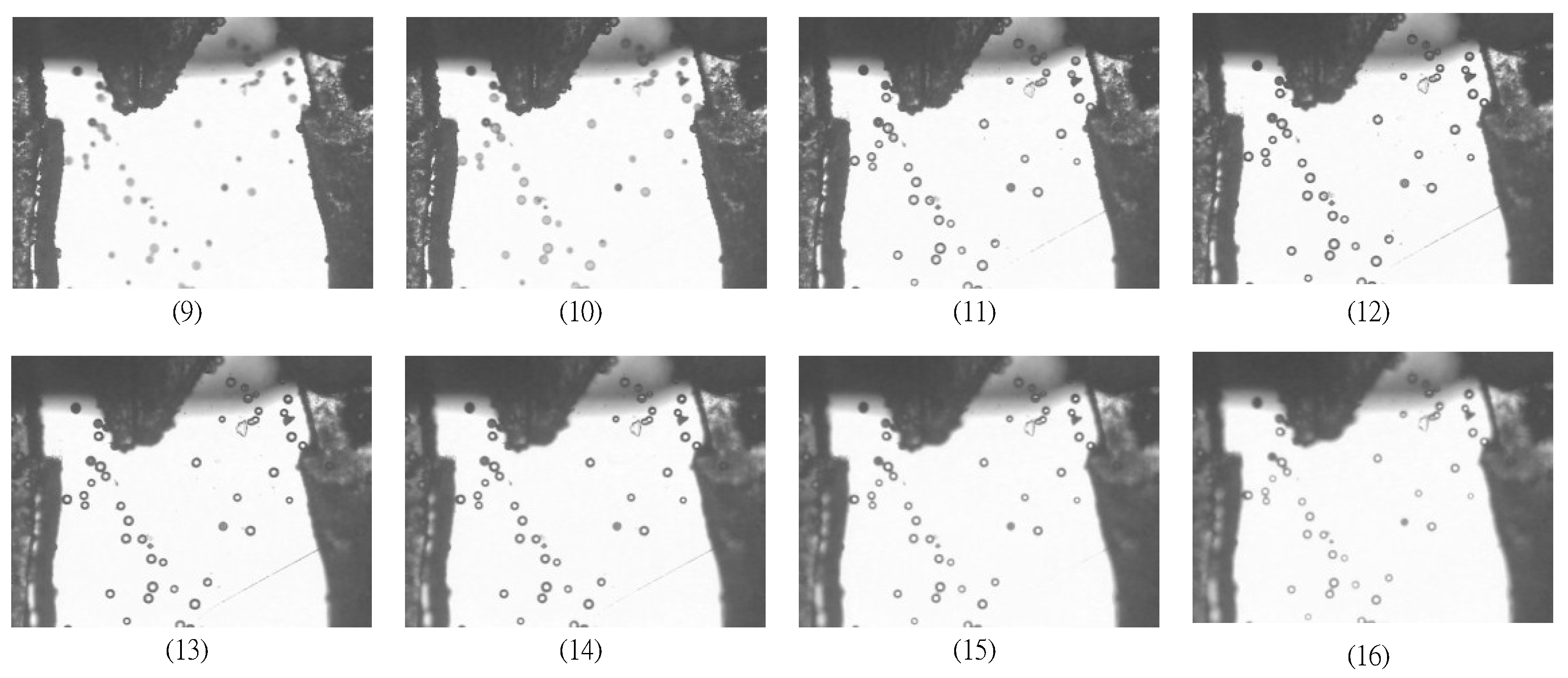
The performance of the proposed autofocusing function on the moving particle was compared with both common focusing functions and wavelet-based focusing functions. In the experimental tests, the particles were made of Polystyrene with density 1.05 g/mL and size 30–50 μm. The microparticles were suspended in water over a long duration. In the experimental tests, the microgripper tips were positioned in the same focus plane as that of microparticles in advance. In utilizing the Autofocusing stage for focusing tests, the block diagram shown in Figure 4 was operated in open loop. The functional block of the Procedure of autofocusing operation in PC was to implement various focusing functions in capturing particle images at different Z positions. The size of particles image was 640 × 480 pixels. The image was captured on every one cyclic rotation of step motor. A total of 29 images were collected. In the sequence of 29 images, Images 1 to 12 were captured in focusing process while Images 13 to 29 were captured in defocusing process. The 29 images in sequence are listed as shown in Figure 4, where the best focusing image is found at image 12.
For the evaluation of noise effect on focusing functions, the relative strength of the added noise is measured by employing SN ratio in dB
where is the size of original image, IM is the grey level of the original image, and IMZ is the grey level of the original image with added noise. In the evaluation of noise effect, a Gaussian white noise with variance 0.0008 was added to each image. The SNR of 29 test images was calculated to give 26 ± 0.2 dB.
3.2.1. Comparison with Common Focusing Functions
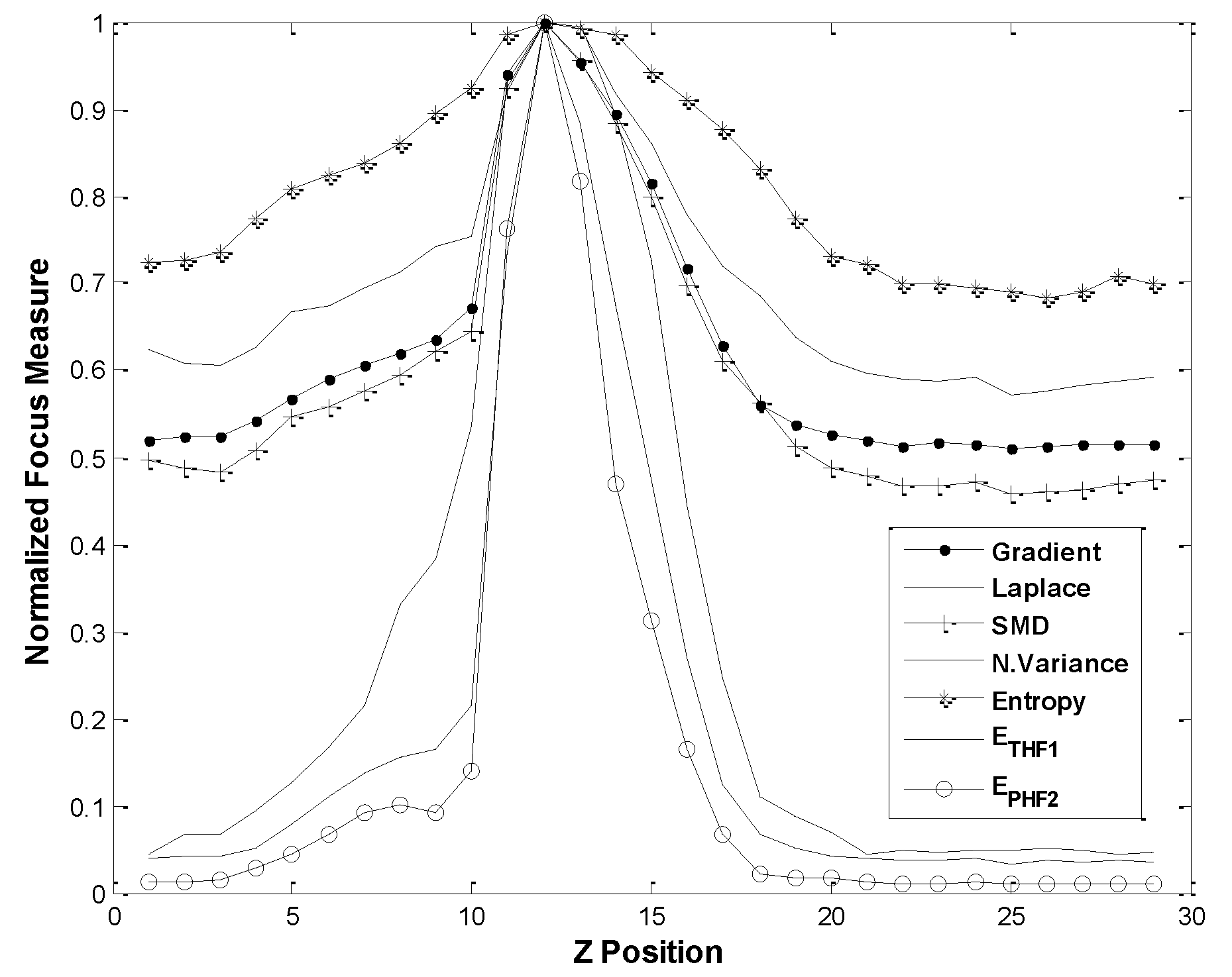
The focusing performances of the proposed ETHF1 and EPHF2 are compared with the common focusing functions: Normalized variance function, Entropy function, Energy Laplace function, Tenenbaum Gradient function, and Sum Modulus Difference (SMD) function. In the wavelet-based algorithms, the mother wavelet was Haar function, i.e., db2 or Daubechies 2. In comparing performance, the evaluated results of autofocusing functions were normalized, as shown in Figure 5. Figure 5 reveals that all focusing functions give the maximum functional values at the same Z position. The Z position at 12 is a correct in-focus position. However, the autofocusing functions ETHF1 and EPHF2 give sharper curves than those of other autofocusing functions. In addition, the performance of the double decomposition EPHF2 is somewhat better than that of single decomposition ETHF1.
3.2.2. Comparison of Wavelet-Based Focusing Functions
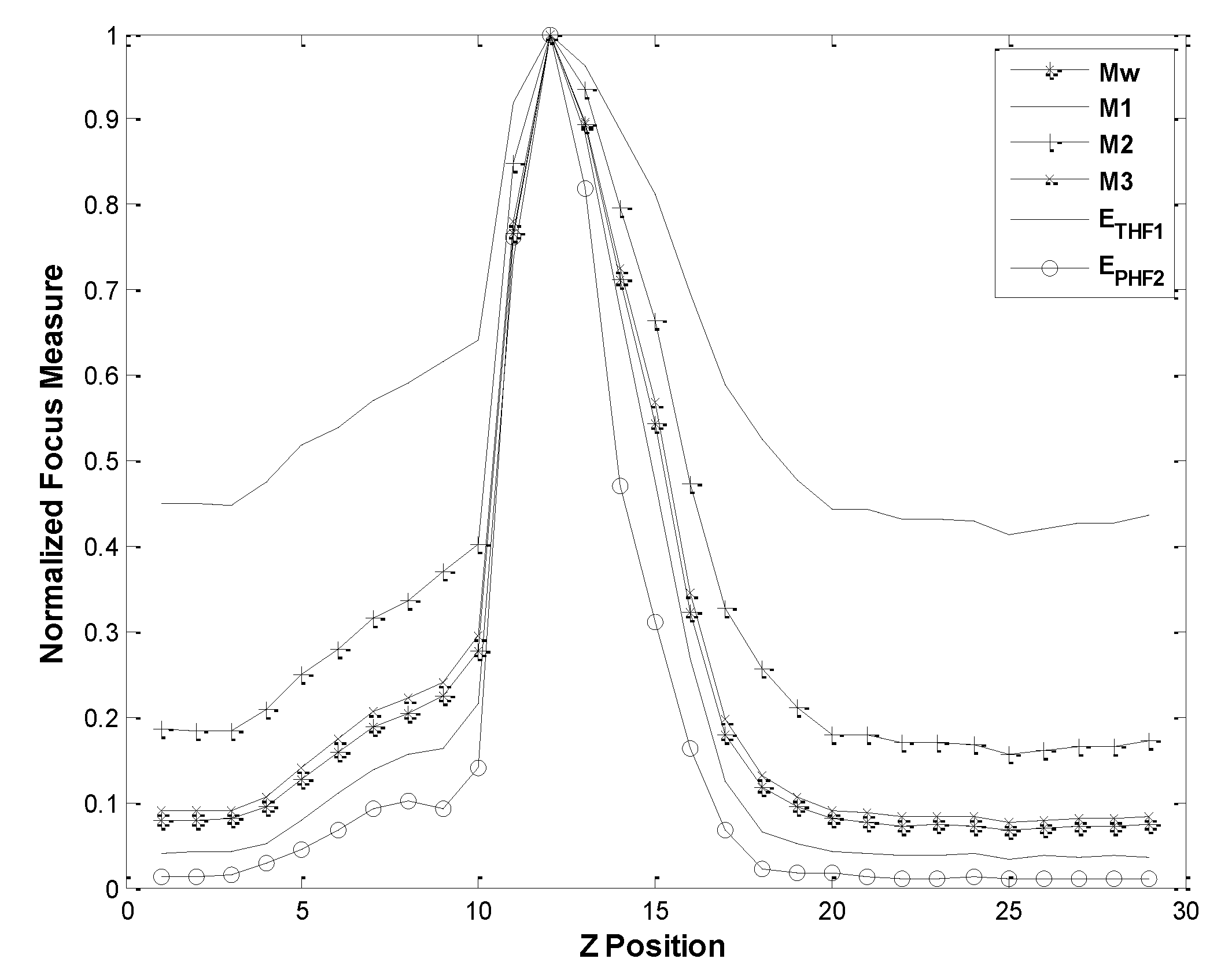
The autofocusing performance by wavelet-entropy function ETHF1 and EPHF2 was compared with the wavelet-based autofocusing functions by Mw, M1, M2 and M3. Here, the autofocusing functions M1, M2 and M3 correspond to W1, W2, and W3 in [30], respectively. In the comparisons of performance, the evaluated results of autofocusing functions were normalized, as displayed in Figure 6. Figure 6 reveals that all focusing functions give the maximum functional values at the same correct Z position. Among the wavelet-based focusing functions, the present double decomposition EPHF2 gives the best performance.
The aforementioned comparison results reveal that the wavelet-entropy function EPHF2 gives the best performance in focusing both microparticles and gripper tips. Therefore, the EPHF2 is selected and employed for the depth estimation to align microgripper tips and moving particle in the same focus plane.
3.3. Peak Position Identification and Depth Estimation in Visual Servo
3.3.1. Peak Position Identification
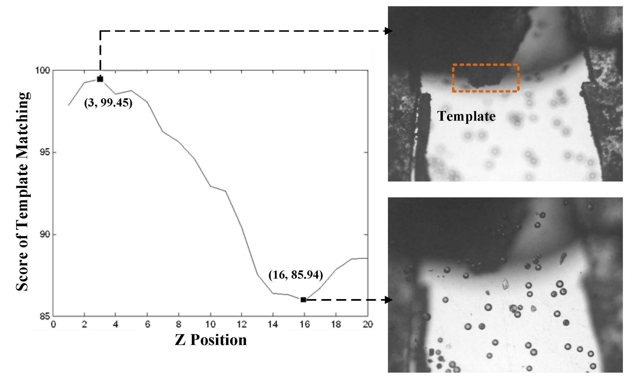
In the image-based microscopic autofocus, Global searching strategy was selected for identifying the peak position of focus measure. The image was captured on every one cyclic rotation of step motor. A total of 20 images were collected. The result of at different Z positions is shown in Figure 7. Figure 7 shows that there are several local maxima in the focusing function. The highest peak at position 16 refers to the image of the in-focus position of micro particles. The next highest peak at position 3 refers to the image of the in-focus position of gripper tips. To obtain the correct identification of the two local maxima in different Z positions, a template of gripper tips, which was not changed in the process of Global searching, was utilized to distinguish two focusing positions by evaluating the matching score between images. Figure 8 displays the matching score in the process of Global searching. In Figure 8, it is observed that the highest score at position 3 is obviously the in-focus position of gripper tips. The lowest score at position 16 is the in-focus position of microparticles.
3.3.2. Depth Estimation
After identifying the in-focus positions of gripper tips and microparticles, the depth between these two positions in Z axis can be evaluated by:
where and are the Z positions of particles and gripper tip, respectively, and is the moving distance of object lens by stepping motor in one revolution. Here, = 22.20 μm/rev. is calculated by the multiplication of gain of step motor, gear ratio, and microscope focus from Figure 3. = 16 rev. and = 3 rev. are obtained from Figure 8. Consequently, the depth between two focusing plane is calculated to give Depth = 288.6 μm. In the servo loop, the depth is calculated in real time for positioning the gripper tips to the same image plane of particles.
The visual servo of autofocusing operation is given by Figure 3. In Figure 3, the functional block of the Procedure of autofocusing operation in PC is to implement the autofocusing operation given in Figure 9. Here, it is noted that the position of gripper tips in Z axis will be moved to the same focusing image plane as that of particles before carrying out the next process of tracking particle.
4. Particle Tracking Process
In utilizing the image-based digital PTV for tracking particle, the first step is to identify and label particles. The next step is to estimate the centroid coordinates of particles. In the last step, the positions of each particle between two consecutive time step images are matched. In considering the requirements of real-time and robust tracking operation, a two-frame scheme by Polar Coordinate System Similarity (PCSS) [44], which is insensitive to experimental parameters and applicable to flows subjected to strong rotation, is first selected and considered for the present applications.
4.1. PCSS Algorithm
The essence of PCSS for finding the matched particles in tracking operation is employing a similarity measure to estimate the changes of both distance and angle of surrounding particles relative to the other particles at two consecutive image frames. The PCSS algorithm is implemented by the following steps:
- Step 1.
- Set an interrogation pattern I centered on the object particle i with radius of R. In the pattern I, the other particles are , where
- Step 2.
- Establish a polar coordinate system with the identified centroid of the particle i as the pole. The relative positions of to i is obtained by their polar radii and angles
- Step 3.
- Repeat Steps 1 and 2 for another interrogation pattern J centered on the object particle j with radius of R. In the pattern J, the other particles are , where and the relative positions of to j is obtained by their polar radii and angles
- Step 4.
- Define a similarity coefficient between patterns I and J aswhere is a step function. and are thresholds of the polar radius and angle, respectively.
- Step 5.
- Calculate the Sij for all candidate particles in the patterns I and J, and find the matched candidate particle i which gives the maximum value of Sij.
The application of PCSS in tracking particles requires the condition of small velocity change in flow field [32]. However, in considering the present application of tracking micron particle, the particle may fluctuate in Brownian motion which causes low value of Sij in tracking algorithm. Therefore, an enhanced PCSS is proposed to incorporate template matching in the tracking algorithm when the value of Sij is not well above a threshold value ρ.
4.2. Template Matching
The representing particle position in fluctuating movement is obtained through template matching technique. By utilizing zero-mean normalized cross-correlation, the correlation between a template image of size and an input image of size can be expressed as
where and are the mean of and , respectively, and the is a subimage of the same size of template. The best match between the template and image is given by the maximum correlation:
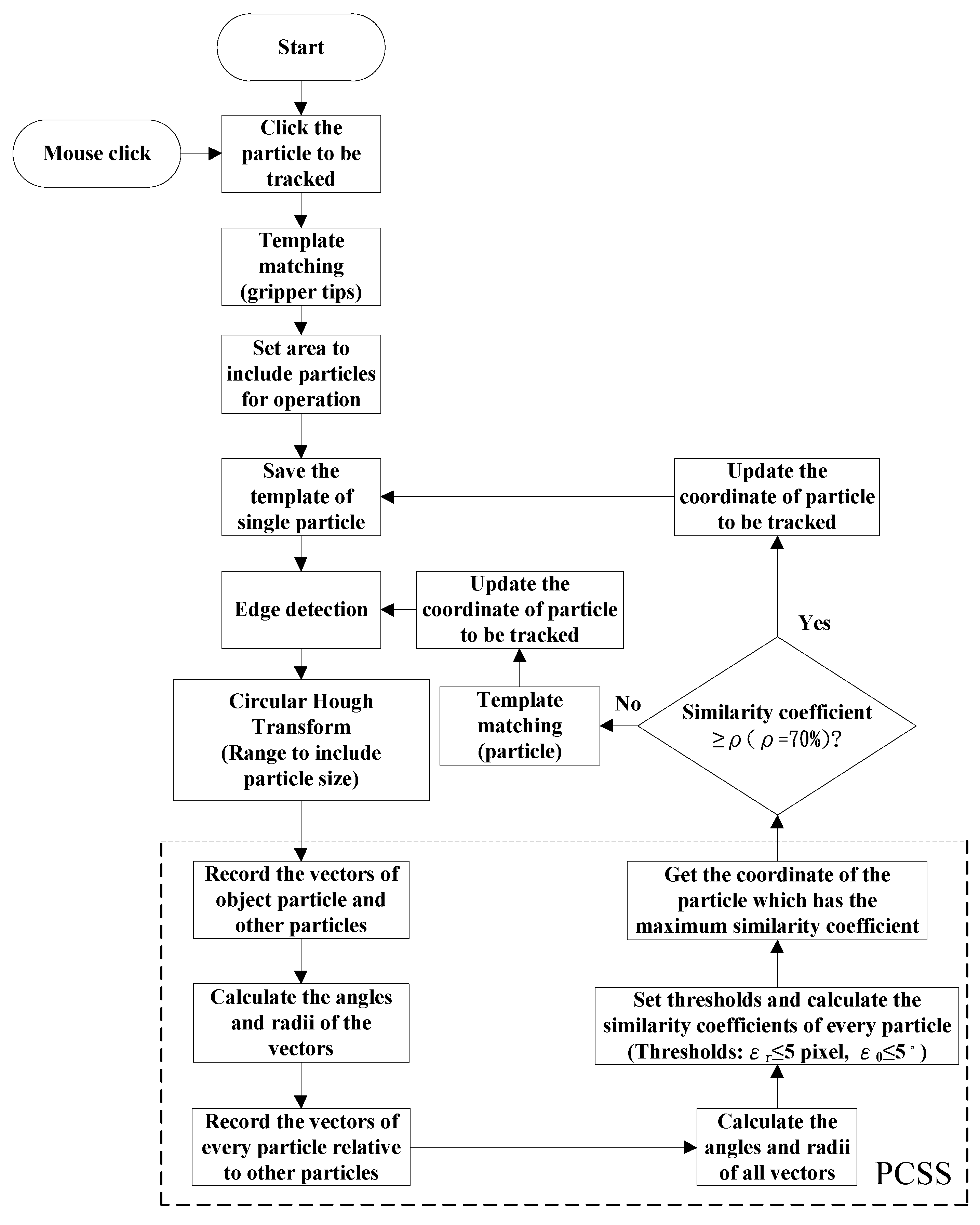
The enhanced PCSS algorithm combines PCSS, edge detection, and template matching in tracking particle movement. In addition, the centroid of particle is estimated by utilizing circular Hough transformation [45]. Regarding the template matching, image pyramids can be employed to enhance the computational efficiency of the correlation-based template detection. The practical operation of the enhanced PCSS algorithm for tracking particle is given by the flowchart shown in Figure 10. In Figure 10, the threshold values are assigned as ρ = 0.7, pixel, and .
5. Gripping Microparticle Tests
A visual-servo automatic micromanipulating system was developed for gripping the moving microparticle suspended in liquid well. The performance of immersing the PU gripper tips into water to grip moving Polystyrene particle was tested. In the experimental test, the microgripper was operated with autofocusing and visual tracking functions in gripping operations. The experimental calibration gave and for the calibrated x, y distance per unit pixel, respectively. The size of microparticle was 30–50 μm. The microparticle was suspended in the water well. The water temperature was 25 °C. To emulate the effect of manipulating performance under flow field, the Object Platform to support the water well was moving with speed 0.6 mm/s which was orthogonal to the gripper axis. The moving speed was set through control panel.
5.1. Working Space in Gripping Operation
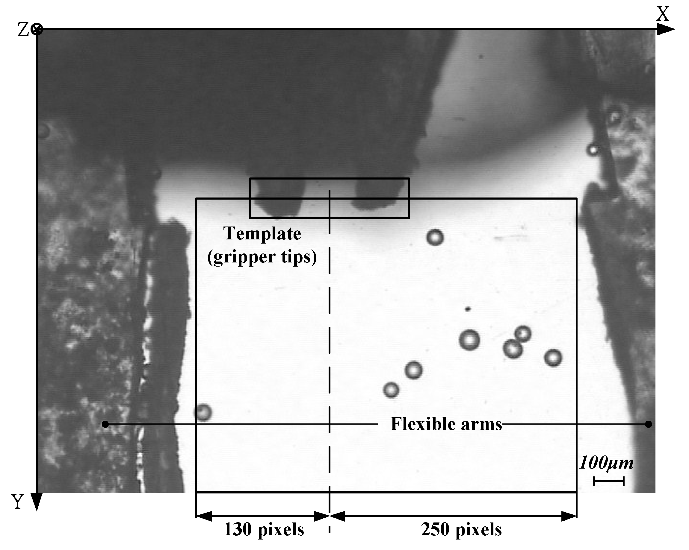
In the operation of gripping particle, the working space will be established. For the horizontal planner area, it is constrained by the sides of two flexible arms and the line passed through the centroid position of gripper tips’ template, as shown in Figure 11. The vertical height is constrained by the 200 μm thickness of microgripper.
5.2. Fine Adjustment of Tracking in Z axis
Regarding the microparticle suspended in water, the focusing position of individual microparticle can change even though the coarse adjustment in the Z-axis focusing operation is completed. Therefore, fine adjustment of focus position is required for the accurate tracking of the specific particle moving in Z axis. For the fine tracking operation, at first, a planner neighborhood region of the identified particle is established:
where Rmax is the maximum diameter of particle, tsampling is the sampling time, and Vx and Vy are the estimated particle speed moving in the X and Y direction, respectively. The center of the region is located at the centroid position of the identified particle, which is estimated by the tracking algorithm. Then, a refocusing search is initiated and the focusing measure of EPHF2 is recorded at each time step. The fine focusing operation will not stop until the peak value of EPHF2 in the next time step is little degraded. The degraded focusing measure can be detected by setting a threshold value :
In the experimental tests, and
5.3. Pre-Positioning and Approaching Operations
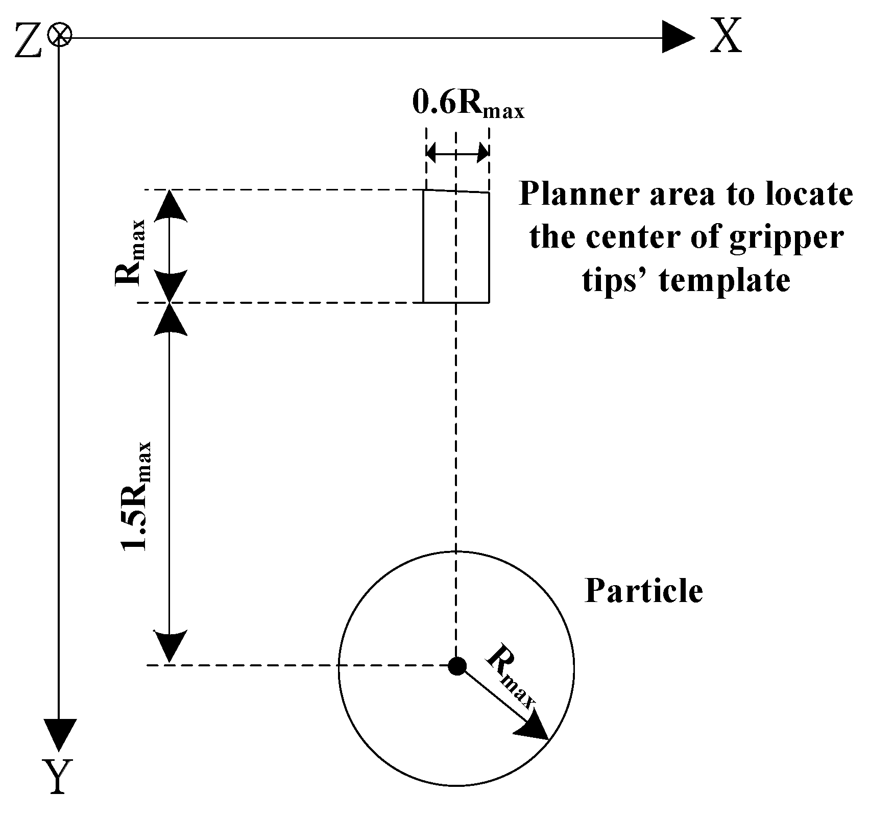
Before carrying out the operation of gripping identified particle, the microgripper will pre-position itself and then approach to the particle by visual servo. In the first pre-positioning step, the microgripper will track the particle in the horizontal X-Y plane. It will not stop until the centroid of gripper tips’ template is located in a region which is close to the identified microparticle. For avoiding collision between gripper tips and particle, a non-colliding safe distance is set to 1.0 Rmax. The planner region to pre-position the gripper is depicted in Figure 12. The gripper will stop when the following conditions are satisfied:
and
where are the X, Y coordinates of particle position, respectively, are the X, Y centroid coordinates of gripper tips’ template, respectively, and are the calculated distances of moving gripper tips to the particle in X, Y directions, respectively. In the second approaching step, the centroid of gripper tips’ template will move to approach the particle. By employing visual servo, the input command for the planner movement of microgripper in X and Y directions can be calculated from Equations (16a) and (16c), respectively. If the particle is not accurately tracked by the gripper, the second approaching step can be interrupted by sending operator’s command.
5.4. Gripping and Releasing Operations
For gripping microparticle, the gripper tip is continuously moving to approach the microparticle. It will not move until the position of particle is located near the centroid of gripper tips’ template. Then, a gripping command is initiated to close and grip the particle. After gripping particle, the gripper will move upward in −Z direction and then hold the particle to 400 μm away in both X and Y directions. Finally, the gripper tips will move to approach the bottom of well and then the gripper will open for releasing microparticle. To avoid adhesion of the particle to the gripper, the microgripper will move fast along −Y for flushing the particle away.
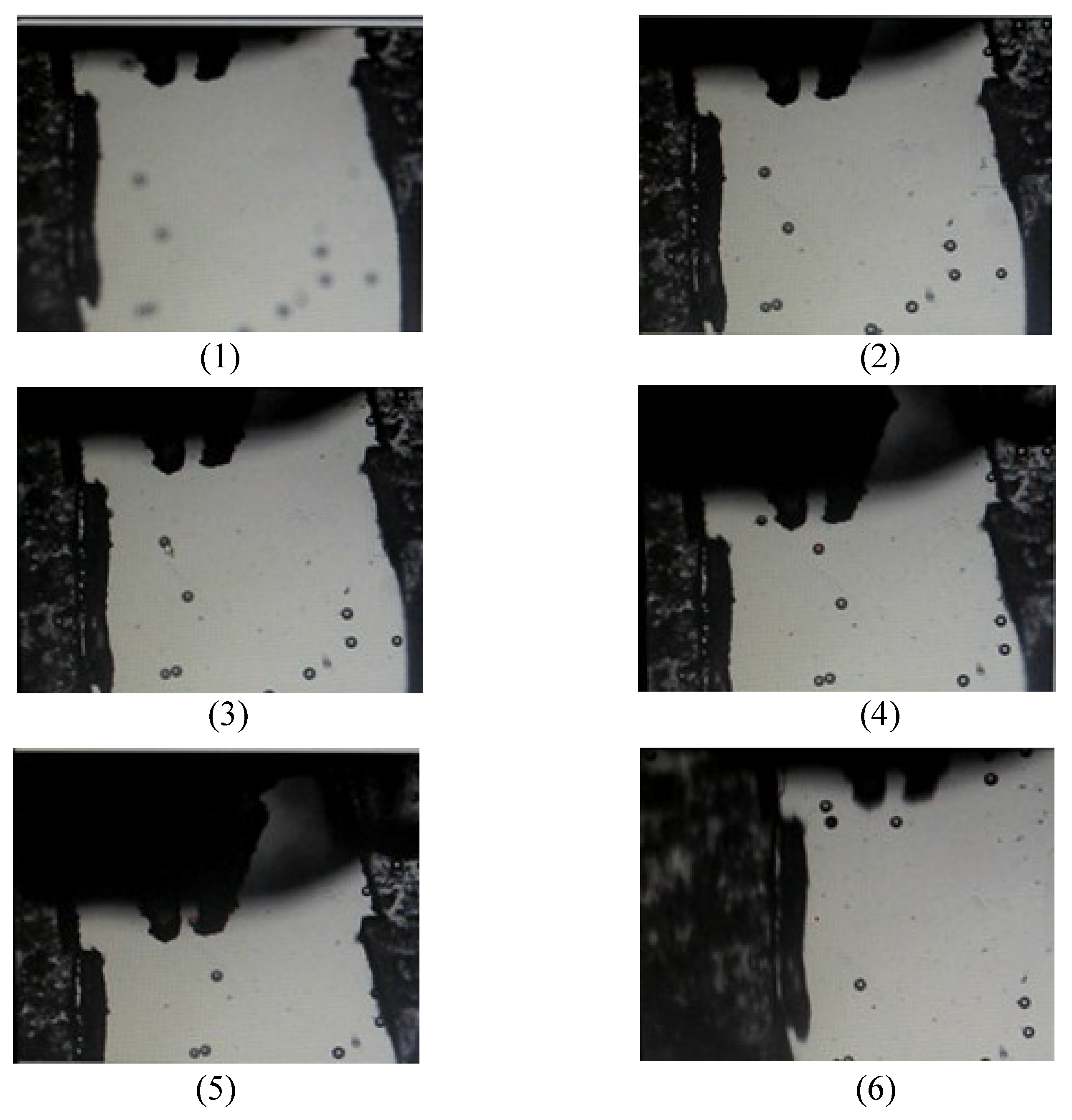
In the gripping microparticle tests, the operational procedures were: (1) initiating the movement of gripper and capturing gripper tips’ template; (2) coarse adjustment; (3) identifying particle by mouse click; (4) fine adjustment; (5) tracking microparticle on X-Y plane; (6) pre-positioning gripper; (7) gripper approaching particle; (8) gripping, transporting, and releasing particle; and (9) homing of gripper. In the initial operation, the microgripper was moved to the position of water surface and the template of gripper tips was captured. During the operational process, the Stop Grasping Command was waited for operator to input if the identified particle was not well tracked by the fine adjustment of focus. The detail operational flowchart is shown in Figure 13. In the performance tests, the images of tracking and gripping identified particle in the 3-D space were captured. The six captured images are displayed in Figure 14. Figure 14(1) shows the initial image in the beginning of global searching for coarse adjustment. Figure 14(2) shows the image of finishing autofocus adjustment. Figure 14(3) displays the image of clicking mouse on the identified particle. Figure 14(4) displays an image in the process of approaching particle before gripping operation. Figure 14(5) displays an image in the process of gripping particle. Figure 14(6) displays an image in the process of releasing particle after the completion of gripping and transporting particle. For the experimental tests, the time expense from the beginning of the global search for coarse adjustment to the actual gripping of the particle was less than 50 s. The successful gripping rate of the present apparatus was 8/10 when the object platform was moving in 0.6 mm/s. The failure was mainly due to the adhesion of micro particles after fine adjustment which caused the inaccurate estimation of particle’s coordinates. As a result, the proposed apparatus can perform better when the particle concentration is somewhat low.
6. Conclusions
An innovative visual-servo automatic micromanipulating system has been developed for gripping the moving microparticle suspended in liquid well. By using an innovative piezoelectric actuated PU micro gripper with flexible arms, a microparticle can be tracked and gripped in a moving work space. A new wavelet-based focus function EPHF2, which revealed the best performance among the surveyed focus functions, was proposed and utilized to estimate the depth for the alignment of microgripper tips and moving particle in the same focus plane. An enhanced PCSS algorithm incorporated with template matching, edge detection method, and circular Hough Transform was implemented for tracking particles under fluctuating and drifting flow. In the performance tests, the images of experimental results in the processes of tracking, gripping, transporting, and releasing 30–50 μm Polystyrene particle in 25 °C water were captured and displayed. For the experimental tests, the time expense from the beginning of the global search for coarse adjustment to the actual gripping of the particle was less than 50 s. The successful gripping rate of the present apparatus was 8/10 when the object platform was moving in 0.6 mm/s. The failure was mainly due to the adhesion of micro particles after fine adjustment which caused the inaccurate estimation of particle’s coordinates. As a result, the proposed apparatus can perform better when the particle concentration is somewhat low.
Author Contributions
Methodology, R.J.C.; Writing-Review & Editing, R.J.C.; Software, Y.C.C.; Investigation, R.J.C. and Y.C.C.
Acknowledgments
The authors would like to thank the Ministry of Science and Technology (MOST) for the partial support provided under contract No. MOST 105-2221-E-006-081.
Conflicts of Interest
The authors declare no conflicts of interest.
References
- Jager, E.W.H.; Inganas, O.; Lundstrom, I. Microrobots for micrometer-size objects in aqueous media: Potential tools for single-cell manipulation. Science 2000, 288, 2335–2338. [Google Scholar] [CrossRef] [PubMed]
- Desai, J.P.; Pillarisetti, A.; Brooks, A.D. Engineering approaches to biomanipulation. Annu. Rev. Biomed. Eng. 2007, 9, 35–53. [Google Scholar] [CrossRef] [PubMed]
- Carrozza, M.C.; Dario, P.; Menciassi, A.; Fenu, A. Manipulating biological and mechanical micro-objects using LIGA-microfabricated end-effectors. In Proceedings of the IEEE International Conference on Robotics & Automation, Leuven, Belgium, 16–20 May 1998; Volume 2, pp. 1811–1816. [Google Scholar]
- Ok, J.; Chu, M.; Kim, C.J. Pneumatically driven microcage for micro-objects in biological liquid. In Proceedings of the Twelfth IEEE International Conference on Micro Electro Mechanical Systems, Orlando, FL, USA, 17 January 1999; pp. 459–463. [Google Scholar]
- Arai, F.; Sugiyama, T.; Luangjarmekorn, P.; Kawaji, A.; Fukuda, T.; Itoigawa, K.; Maeda, A. 3D Viewpoint Selection and Bilateral Control for Bio-Micromanipulation. In Proceedings of the IEEE International Conference on Robotics & Automation, San Francisco, CA, USA, 24–28 April 2000; pp. 947–952. [Google Scholar]
- Beyeler, F.; Neild, A.; Oberti, S.; Bell, D.J.; Sun, Y. Monolithically fabricated microgripper with integrated force sensor for manipulating microobjects and biological cells aligned in an ultrasonic field. J. Microelectromech. Syst. 2007, 16, 7–15. [Google Scholar] [CrossRef]
- Feng, L.; Wu, X.; Jiang, Y.; Zhang, D.; Arai, F. Manipulating Microrobots Using Balanced Magnetic and Buoyancy Forces. Micromachines 2018, 9, 50. [Google Scholar] [CrossRef]
- Potrich, C.; Lunelli, L.; Bagolini, A.; Bellutti, P.; Pederzolli, C.; Verotti, M.; Belfiore, N.P. Innovative Silicon Microgrippers for Biomedical Applications: Design, Mechanical Simulation and Evaluation of Protein Fouling. Actuators 2018, 7, 12. [Google Scholar] [CrossRef]
- Chronis, N.; Lee, L.P. Electrothermally activated SU-8 microgripper for single cell manipulation in solution. J. Microelectromech. Syst. 2005, 14, 857–863. [Google Scholar] [CrossRef]
- Hériban, D.; Agnus, J.; Gauthier, M. Micro-manipulation of silicate micro-sized particles for biological applications. In Proceedings of the 5th International Workshop on Microfactories, Becanson, France, 25–27 October 2006; p. 4. [Google Scholar]
- Solano, B.; Wood, D. Design and testing of a polymeric microgripper for cell manipulation. Microelectron. Eng. 2007, 84, 1219–1222. [Google Scholar] [CrossRef]
- Han, K.; Lee, S.H.; Moon, W.; Park, J.S.; Moon, C.W. Design and fabrication of the microgripper for manipulation the cell. Integr. Ferroelectr. 2007, 89, 77–86. [Google Scholar] [CrossRef]
- Colinjivadi, K.S.; Lee, J.B.; Draper, R. Viable cell handling with high aspect ratio polymer chopstick gripper mounted on a nano precision manipulator. Microsyst. Technol. 2008, 14, 1627–1633. [Google Scholar] [CrossRef]
- Kim, K.; Liu, X.; Zhang, Y.; Sun, Y. Nanonewton force-controlled manipulation of biological cells using a monolithic MEMS microgripper with two-axis force feedback. J. Micromech. Microeng. 2008, 18, 055013. [Google Scholar] [CrossRef]
- Kim, K.; Liu, X.; Zhang, Y.; Cheng, J.; Xiao, Y.W.; Sun, Y. Elastic and viscoelastic characterization of microcapsules for drug delivery using a force-feedback MEMS microgripper. Biomed. Microdevices 2009, 11, 421–427. [Google Scholar] [CrossRef] [PubMed]
- Zhang, R.; Chu, J.; Wang, H.; Chen, Z. A multipurpose electrothermal microgripper for biological micro-manipulation. Microsyst. Technol. 2013, 89, 89–97. [Google Scholar] [CrossRef]
- Di Giamberardino, P.; Bagolini, A.; Bellutti, P.; Rudas, I.J.; Verotti, M.; Botta, F.; Belfiore, N.P. New MEMS tweezers for the viscoelastic characterization of soft materials at the microscale. Micromachines 2018, 9, 15. [Google Scholar] [CrossRef]
- Cauchi, M.; Grech, I.; Mallia, B.; Mollicone, P.; Sammut, N. Analytical, numerical and experimental study of a horizontal electrothermal MEMS microgripper for the deformability characterisation of human red blood cells. Micromachines 2018, 9, 108. [Google Scholar] [CrossRef]
- Malachowski, K.; Jamal, M.; Jin, Q.R.; Polat, B.; Morris, C.J.; Gracias, D.H. Self-folding single cell grippers. Nano Lett. 2014, 14, 4164–4170. [Google Scholar] [CrossRef] [PubMed]
- Ghosh, A.; Yoon, C.; Ongaro, F.; Scheggi, S.; Selaru, F.M.; Misra, S.; Gracias, D.H. Stimuli-responsive soft untethered grippers for drug delivery and robotic surgery. Front. Mech. Eng. 2017, 3, 7. [Google Scholar] [CrossRef]
- Wang, W.H.; Lin, X.Y.; Sun, Y. Contact detection in microrobotic manipulation. Int. J. Robot. Res. 2007, 26, 821–828. [Google Scholar] [CrossRef]
- Inoue, K.; Tanikawa, T.; Arai, T. Micro-manipulation system with a two-fingered micro-hand and its potential application in bioscience. J. Biotechnol. 2008, 133, 219–224. [Google Scholar] [CrossRef] [PubMed]
- Chen, L.; Yang, Z.; Sun, L. Three-dimensional tracking at micro-scale using a single optical microscope. In Proceedings of the International Conference on Intelligent Robotics and Applications, Wuhan, China, 15–17 October 2008; pp. 178–187. [Google Scholar]
- Duceux, G.; Tamadazte, B.; Fort-Piat, N.L.; Marchand, E.; Fortier, G.; Dembele, S. Autofocusing-based visual servoing: Application to MEMS micromanipulation. In Proceedings of the 2010 International Symposium on Optomechatronic Technologies (ISOT), Toronto, ON, Canada, 25–27 October 2010; p. 11747002. [Google Scholar]
- Subbarao, M.; Tyan, J.K. Selecting the optimal focus measure for autofocusing and depth-from-focus. IEEE Trans. Pattern Anal. Mach. Intell. 1998, 20, 864–870. [Google Scholar] [CrossRef] [Green Version]
- Brenner, J.F.; Dew, B.S.; Horton, J.B.; King, T.; Neurath, P.W.; Selles, W.D. An automated microscope for cytologic research, a preliminary evaluation. J. Histochem. Cytochem. 1976, 24, 100–111. [Google Scholar] [CrossRef] [PubMed]
- Groen, F.C.A.; Young, I.T.; Ligthart, G. A comparison of different focus functions for use in autofocus algorithms. Cytometry 1985, 6, 81–91. [Google Scholar] [CrossRef] [PubMed] [Green Version]
- Firestone, L.; Cook, K.; Culp, K.; Talsania, N.; Preston, K., Jr. Comparison of autofocus methods for automated microscopy. Cytometry 1991, 12, 195–206. [Google Scholar] [CrossRef] [PubMed]
- Santos, A.; De Solorzano, C.O.; Vaquero, J.J.; Peña, J.M.; Malpica, N.; Del Pozo, F. Evaluation of autofocus functions in molecular cytogenetic analysis. J. Microsc. 1997, 188, 264–272. [Google Scholar] [CrossRef] [PubMed] [Green Version]
- Sun, Y.; Duthaler, S.; Nelson, B.J. Autofocusing in computer microscopy: Selecting the optimal focus algorithm. Microsc. Res. Tech. 2004, 65, 139–149. [Google Scholar] [CrossRef] [PubMed]
- Xie, H.; Rong, W.B.; Sun, L.N. Construction and Evaluation of a Wavelet-Based Focus Measure for Microscopy Imaging. Microsc. Res. Tech. 2007, 70, 987–995. [Google Scholar] [CrossRef] [PubMed]
- Shindler, L.; Moroni, M.; Cenedese, A. Spatial–temporal improvements of a two-frame particle-tracking algorithm. Meas. Sci. Technol. 2010, 21, 1–15. [Google Scholar] [CrossRef]
- Chang, R.J.; Lai, Y.H. Design and implementation of micromechatronic systems: SMA drive polymer microgripper. In Design, Control and Applications of Mechatronic Systems in Engineering; Sahin, Y., Ed.; InTechOpen: London, UK, 2017. [Google Scholar]
- Yao, Y.; Abidi, B.; Doggaz, N.; Abidi, M. Evaluation of sharpness measures and search algorithms for the auto focusing of high-magnification images. Proc. SPIE 2006, 6246, 62460G. [Google Scholar] [CrossRef] [Green Version]
- Kou, C.J.; Chiu, C.H. Improved auto-focus search algorithms for CMOS image-sensing module. J. Inf. Sci. Eng. 2011, 27, 1377–1393. [Google Scholar]
- Mendelsohn, M.L.; Mayall, B.H. Computer-oriented analysis of human chromosomes-III focus. Comput. Biol. Med. 1972, 2, 137–150. [Google Scholar] [CrossRef]
- Krotkov, E. Focusing. Int. J. Comput. Vis. 1987, 1, 223–237. [Google Scholar] [CrossRef]
- Subbarao, M.; Choi, T.S.; Nikzad, A. Focusing techniques. J. Opt. Eng. 1993, 32, 2824–2836. [Google Scholar] [CrossRef]
- Yeo, T.T.E.; Ong, S.H.; Jayasooriah; Sinniah, R. Autofocusing for tissue microscopy. Image Vis. Comput. 1993, 11, 629–639. [Google Scholar] [CrossRef]
- Nayar, S.K.; Nakagawa, Y. Shape from Focus. IEEE Trans. Pattern Anal. Mach. Intell. 1994, 16, 824–831. [Google Scholar] [CrossRef]
- Vollath, D. Automatic focusing by correlative methods. J. Microsc. 1987, 147, 279–288. [Google Scholar] [CrossRef]
- Vollath, D. The influence of the scene parameters and of noise on the behavior of automatic focusing algorithms. J. Microsc. 1988, 151, 133–146. [Google Scholar] [CrossRef]
- Yang, G.; Nelson, B.J. Wavelet-based autofocusing and unsupervised segmentation of microscopic images. In Proceedings of the IEEE/RSJ International Conference on Intelligent Robots and Systems, Las Vegas, NV, USA, 27–31 October 2003; pp. 2143–2148. [Google Scholar]
- Ruan, X.D.; Zhao, W.F. A novel particle tracking algorithm using polar coordinate system similarity. Acta Mech. Sin. 2005, 21, 430–435. [Google Scholar] [CrossRef]
- Duda, R.O.; Hart, P.E. Use of the Hough Transformation to detect lines and curves in pictures. Commun. ACM 1972, 15, 11–15. [Google Scholar] [CrossRef]
Figure 1.
Micromanipulation system (overlapped by a photo of microgripper with bending flexible arms in liquid well).
Figure 1.
Micromanipulation system (overlapped by a photo of microgripper with bending flexible arms in liquid well).

Figure 2.
Detail components and assembly of Gripper and Actuator Mechanism.

Figure 3.
Block diagram of focusing control in open or closed loop through PC.

Figure 4.
A sequence of eight images from total 29 images are displayed to illustrate the test of autofocusing functions. Images (1)–(12) are captured in the focusing process while Images (13)–(29) are captured in the defocusing process. Note that the best focusing image is at Image (12).
Figure 4.
A sequence of eight images from total 29 images are displayed to illustrate the test of autofocusing functions. Images (1)–(12) are captured in the focusing process while Images (13)–(29) are captured in the defocusing process. Note that the best focusing image is at Image (12).

Figure 5.
Comparisons of focus measures by wavelet-entropy ETHF1, EPHF2 and other common focus functions (SNR of test image = 26 ± 0.2 dB).
Figure 5.
Comparisons of focus measures by wavelet-entropy ETHF1, EPHF2 and other common focus functions (SNR of test image = 26 ± 0.2 dB).

Figure 6.
Comparisons of focus measures by wavelet-entropy ETHF1, EPHF2 and other wavelet-based functions (SNR of test image = 26 ± 0.2 dB).
Figure 6.
Comparisons of focus measures by wavelet-entropy ETHF1, EPHF2 and other wavelet-based functions (SNR of test image = 26 ± 0.2 dB).

Figure 7.
Focus measure of in focusing gripper tips and particles.

Figure 8.
Score of template matching by employing the template of gripper tips.

Figure 9.
Flowchart of autofocusing operation to align microgripper tips and moving particles in the same focus plane (coarse adjustment).
Figure 9.
Flowchart of autofocusing operation to align microgripper tips and moving particles in the same focus plane (coarse adjustment).

Figure 10.
Enhanced PCSS for tracking micro particle on X-Y plane.

Figure 11.
Horizontal planner area to constrain moving particles.

Figure 12.
Planner area to locate the gripper by the center of gripper tips’ template in pre-positioning operation.
Figure 12.
Planner area to locate the gripper by the center of gripper tips’ template in pre-positioning operation.

Figure 13.
The processes of tracking and gripping particle moving in 3-D space.

Figure 14.
Results of tracking and gripping particle in 3-D space: (1) beginning of global searching for coarse adjustment; (2) finishing autofocus adjustment; (3) identifying particle by clicking mouse; (4) approaching particle; (5) gripping particle; and (6) releasing particle after completion of gripping and transporting particle.

© 2018 by the authors. Licensee MDPI, Basel, Switzerland. This article is an open access article distributed under the terms and conditions of the Creative Commons Attribution (CC BY) license (http://creativecommons.org/licenses/by/4.0/).
Share and Cite
MDPI and ACS Style
Chang, R.-J.; Chien, Y.-C. Polymer Microgripper with Autofocusing and Visual Tracking Operations to Grip Particle Moving in Liquid. Actuators 2018, 7, 27. https://doi.org/10.3390/act7020027
AMA Style
Chang R-J, Chien Y-C. Polymer Microgripper with Autofocusing and Visual Tracking Operations to Grip Particle Moving in Liquid. Actuators. 2018; 7(2):27. https://doi.org/10.3390/act7020027
Chicago/Turabian StyleChang, Ren-Jung, and Yu-Cheng Chien. 2018. "Polymer Microgripper with Autofocusing and Visual Tracking Operations to Grip Particle Moving in Liquid" Actuators 7, no. 2: 27. https://doi.org/10.3390/act7020027
Note that from the first issue of 2016, this journal uses article numbers instead of page numbers. See further details here.