New Layouts of Fiber Reinforcements to Enable Full Finger Motion Assist with Pneumatic Multi-Chamber Elastomer Actuators


1
Department of Medical Engineering, Graduate school of Engineering, Chiba University, Inage-ku, Yayoi-cho 1-33, Chiba 263-8522, Japan
2
Center for Frontier Medical Engineering, Chiba University, Inage-ku, Yayoi-cho 1-33, Chiba 263-8522, Japan
*
Author to whom correspondence should be addressed.
Actuators 2018, 7(2), 31; https://doi.org/10.3390/act7020031
Submission received: 7 April 2018
/
Revised: 1 June 2018
/
Accepted: 13 June 2018
/
Published: 18 June 2018
Abstract
:Fiber-reinforced fluid-driven elastomer actuators have enabled the production of simple, low-cost and safe hand rehabilitation devices. However, so far, the actuators support only finger flexion-extension, and little has been reported on abduction-adduction, which is essential for manipulation tasks and grasping larger objects. The technical design difficulty of realizing abduction-adduction lies in the suppression of interference effects between the metacarpophalangeal (MCP) joint’s two orthogonal motion axes, caused by the necessary multi-chamber actuator structure and its reinforcements, under strong spatial constraints. This problem has not been solved yet, regardless of research efforts on designing various actuator structures. In this study, our goal was to enable flexion of all three finger joints and abduction-adduction of the MCP joint, while minimizing the interference and realizing required ranges of motion. For this, we propose two new types of fiber reinforcements (separate single loops and two-directional hitching) and their combination to direct a multi-chamber structure’s expansion and strengthen its force output into the wanted directions. The reinforcements’ effects on actuator response were evaluated by attaching prototypes to a dummy finger and measuring its range of motion and related joint torques and forces. Results showed that the single loops provided length extension, while the hitching constrained it from the bottom at the centerline and strengthened flexion. When combined, they could be used to adjust the amount of length extension and flexion along the actuator, without detrimentally affecting the flexion or abduction-adduction functions. In conclusion, the two new reinforcement types have the potential of being a major design factor for fitting the actuators’ response for different users’ finger kinematics.
1. Introduction
1.1. Background
The field of soft robotics has received increasing attention in the past decade. New materials and manufacturing methods have enabled the fabrication of novel structures and systems for applications that require robustness and safety through compliance, especially when interacting with humans [1,2,3,4]. One such application is assistive devices for upper limb rehabilitation [2,5].
Soft robotics can provide safe, effective and intensive exercises, specifically in cases where safety and patient comfort are a priority [2]. For example, after a stroke, there is an approximately three-month window for most of the neurological recovery to happen, and intensive rehabilitation is required during this sensitive period to enable full potential recovery [6,7]. This type of need in rehabilitation has driven research groups around the world to explore the design space of soft actuators for affordable at-home hand motion assist and rehabilitation [2,8]. These devices could enable earlier hospital discharge, as the patient could perform the exercises independently at home at his/her own pace, having to go to the rehabilitation clinic only for control checks. Several motion-assist glove systems have also been developed to the clinical trial phase [2], e.g., by Polygerinos et al. [9] and Yap et al. [8].
Still, to the best of our knowledge, none of the studies so far have achieved full separate, or simultaneous, motion assist of all finger joints with a single wearable system [2]. Firstly, they have excluded abduction-adduction, which is an important function in activities of daily living, as it enables many manipulation tasks and grasping of larger objects [10]. Concentrating only on more general motions, such as power grasp, may leave this type of fine manipulation function unrecoverable after the critical three-month period after stroke [6,7,11]. Secondly, many studies [8,9,12,13,14] combine the motion assist of the interphalangeal (IP) and metacarpophalangeal (MCP) joints to be controlled by only one input, which then excludes multiple motion combinations that involve bending the joints separately.
Only Chua et al. [15] have concentrated on the sideways motion of the fingers. Their device was designed to correct the posture of a finger that is deformed due to rheumatoid arthritis by pressurizing and stiffening two actuators attached to it. However, this was not the same as assistance of abduction-adduction motion, as the device only pulled the bent finger towards the centerline. Furthermore, they placed the other actuator under the finger, removing the possibility of flexion-extension.
In another study by Yun et al. [16], an actuator was placed between the thumb and index finger to provide sideways motion of the thumb’s carpometacarpal joint. This idea could be possibly expanded to include the abduction-adduction of the fingers’ MCP joint, but they have not explored this option.
Therefore, there is a need to develop novel soft actuator structures to enable support for the fingers’ sideways abduction-adduction motion, while providing actuation in the flexion-extension direction.
1.2. Related Research
Many groups have developed different types of fluid-driven elastomer actuators [9,17,18,19,20,21]. These actuators consist of one or more chambers, enclosed in a polymer, which can be reinforced with strain-limiting materials. When the chambers are pressurized, the actuator deforms like a balloon, following the constraints set by four basic principles [20]:
- (1)
- (2)
- (3)
- (4)
A major difficulty in implementing full finger motion support is the complexity of designing an actuator structure that could control the MCP joint’s two orthogonal degrees of freedom (DoF) separately and simultaneously. Considering the four principles, it is necessary to use either a multi-chamber structure [20,30] or separate actuator modules [16] on the joint to enable its multi-directional control without the two functions interfering with each other.
Furthermore, the available space on the hand is limited. To not obstruct the flexion of the fingers, actuators cannot be placed on the palmar side. Furthermore, placing actuator modules between the fingers to push them apart [16] would disable them from moving close to each other and lead to losing their separate flexion by coupling them together. The remaining option is to place the actuators on top of the joint and include both functions inside the same multi-chamber structure.
We explored this in our previous study [20] on multi-chamber fiber-reinforced actuators for MCP joint motion assist. We presented several different options for the actuator geometry in combination with a set of embedded reinforcements. We tested their ability to control the two DoFs of the MCP joint separately by measuring their free motion and attaching them to a dummy joint for torque measurements. However, the presented approaches all had disadvantages that made them not fully suitable for the intended purpose. Four of the five prototypes had a clear forwards deviation during the abduction-adduction motion even without being connected to a finger. This was caused by the reinforcements, which included a strain restricting layer on the bottom side, and commonly-used fiber reinforcement patterns around the actuators to constrain radial expansion. The fifth prototype’s response was balanced in free motion. It had four parallel chambers, and the structure was reinforced only with separate single loops of fiber. However, the abduction-adduction function was too strong compared to flexion, and the actuator’s length extension was excessive due to not having a constraint on it. Furthermore, the amount of inputs could have been reduced to three to remove redundancy and simplify control.
A common method of placing fiber reinforcements is to wind one or more fibers at specific angles around the actuator [26,27]. A single fiber can be used to induce twisting, while fibers at different angles can be used to induce flexion and length extension, depending on the fibers’ angles relative to each other and the actuator’s longitudinal axis [26,27]. This way of placing the reinforcements can be used for simple internal structures that should achieve only a single motion of a joint. However, when reinforcing a multi-chamber structure to control a 2-DoF joint, the commonly-used reinforcement patterns cause the two functions to degrade [20].
Thus, a combination of an internal structure and a reinforcement layout that would allow for a separate and simultaneous two-directional control of the connected MCP joint motion has not been presented so far.
1.3. Goals of This Study
In this study, we propose two new types of fiber reinforcements (separate single loops and two-directional hitching), and their combination, to be used on multi-chamber elastomer actuators to direct their expansion in the wanted directions. We aimed to minimize detrimental effects between motion assist of the two orthogonal DoFs of a connected finger’s MCP joint. We also considered how the reinforcements affect a single-chamber structure for IP joint assist. In other words, our goal was to enable abduction-adduction with minimal flexion and flexion of the three joints with minimal sideways motion and twisting.
We analyzed how the two reinforcement types and their combination can be used to modify and strengthen the actuator’s motion and force output and realize the required range of motion (RoM) for an assisted dummy finger’s joints.
The description of our study is divided into two, the design of the actuator structure and fiber reinforcements and the fabrication and experimental evaluation of prototypes.
2. Actuator Design
In this section, we outline our actuators’ functional requirements and describe the design of the prototypes we fabricated and evaluated.
2.1. Functional Requirements
Actuators connected to assisted fingers need to provide adequate RoM and apply enough torque on the joints to enable effective motion assist for rehabilitation. Our focus in this study was on MCP and IP joint flexion and MCP joint abduction-adduction motions. We excluded joint extension, as we saw it to be mutually exclusive with flexion in rehabilitation scenarios, as usually patients need either only flexion or extension assist. Thus, it was implemented only as a passive function through material stiffness.
Normally, the IP joints’ motion is coupled [31,32], and separate control of the distal IP (DIP) joint is not possible for most individuals. Thus, their motion assist should be done together. Hahn et al. [31] describe a relation of 1° of proximal IP (PIP) joint flexion to 0.76° of DIP joint flexion, which is in agreement with the results of Leijnse et al. [32]. This gives us a bending ratio of approximately:
Considering this relationship and the normal human finger joint RoMs [32,33], we set the motion assist RoM requirements as in Table 1.
In order to have the fingers bend to these target values, the actuators need to transfer enough torque to the joints. The torque requirements are naturally different for a relaxed hand and a hand that is suffering from joint stiffness caused by either scar tissue or possible muscle spasticity related to neurological impairments. We approximated the minimum and maximum torques (Table 2) based on the results of our previous study on MCP joint assist actuators [20] and acceptable torques for assisting the index finger joint motions by Kawasaki et al. [34], respectively.
The actuators also need to expand in length to compensate for the length difference between the top of a straight and a flexed joint. This difference causes the point directly above the joint centers to move as the finger flexes. This length change varies greatly between individuals and between the four fingers, as it depends on the thickness of the joints and the soft tissues on them. Thus, in this study, we used approximated arbitrary values for it.
2.2. Actuator Structure
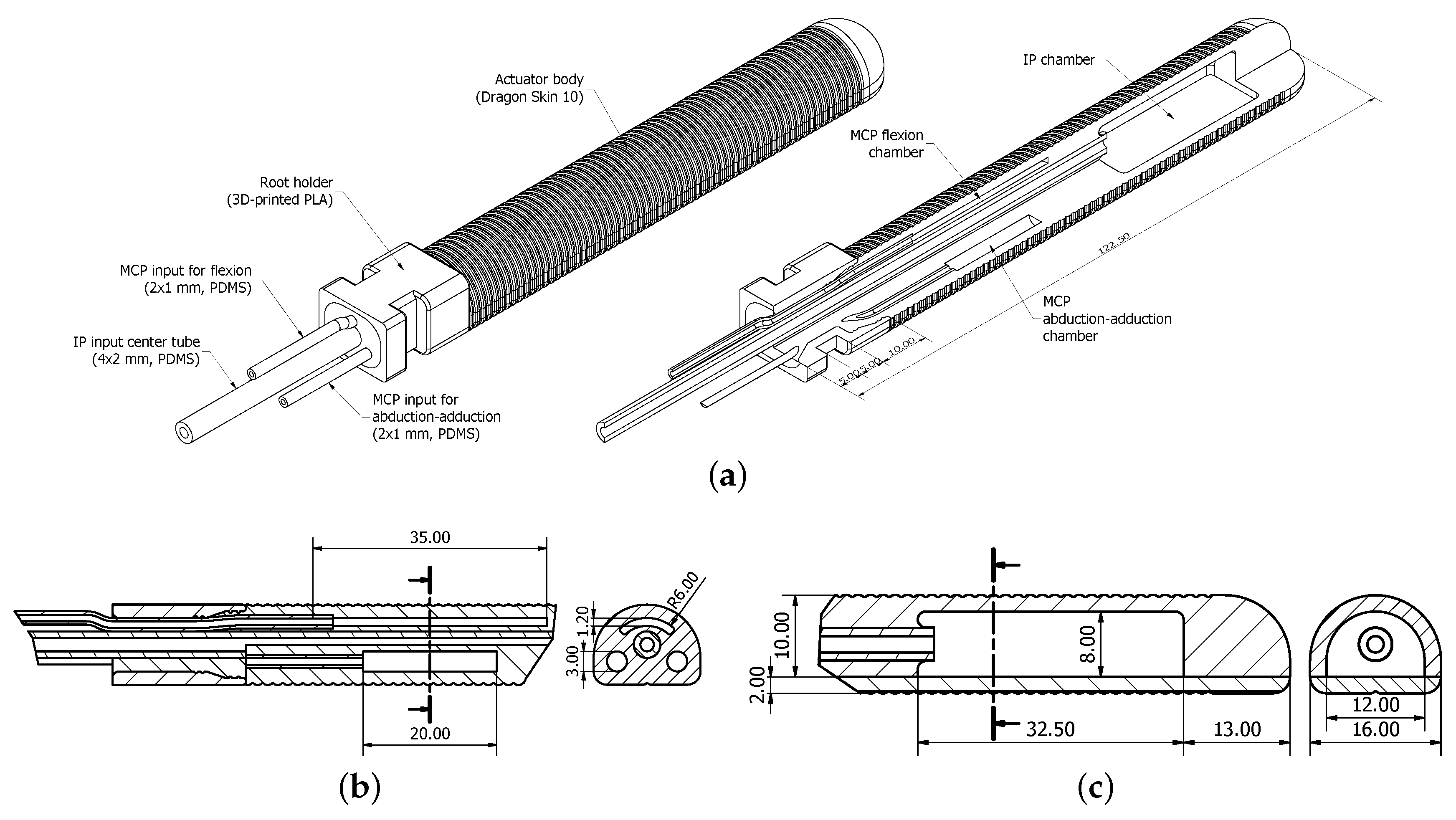
To enable separate assist of MCP and IP joints, we designed an actuator structure with four chambers; three for MCP joint and one for IP joints (Figure 1). Many of the design decisions were based on the analysis of a four-chamber MCP structure in our previous study [20]. Differing from before, we changed the cross-sectional shape to be a half-circle instead of a rectangle to reduce the initial deformation towards a circular shape during inflation and to make the actuators more compact and aesthetic. General actuator dimensions were made to match those of a collaborating patient’s index finger, regarding overall length, width and distances between joints. The dimensions of the chambers were decided based on the available space and through iterative testing with prototypes.
The internal structure of the MCP joint section of the actuator is shown in Figure 1b. The center of the actuator consisted of a 4-mm PDMS silicone tube, which served a dual purpose of restricting the actuator deformation from its center and providing pressure input for the distal joints. The 20 mm-long chambers for abduction-adduction were placed symmetrically on both sides of the central tube, slightly under it. This was to cause the actuator to bend slightly backwards, working against the constraint from a connected finger, and to bring the resultant motion closer to be more directly sideways. The flexion chamber had a curved wider cross-section to accommodate the space restriction above the center tube and to spread the effect of the structure’s deformation evenly on both sides to make it directed always forwards without twisting.
The IP joint section of the actuator (Figure 1c) had only one continuous chamber for controlling both joints with the same input, because of the coupled nature of their motion. Furthermore, as the IP joints move only in the flexion-extension direction, this chamber had a simple geometry, similar to, e.g., the one by Wang et al. [35].
The root part of each actuator was designed to be hard plastic for easily connecting the actuators to a test bench or a supporting orthotic structure on the hand. The root connector was hollow and had pressure input tubing passing through it. It was fixed in place by casting silicone around the tubing.
Finally, guide grooves for the fiber reinforcements on the actuator were set to be at a 1.5-mm interval along the actuator (Figure 1).
2.3. Fiber Reinforcements
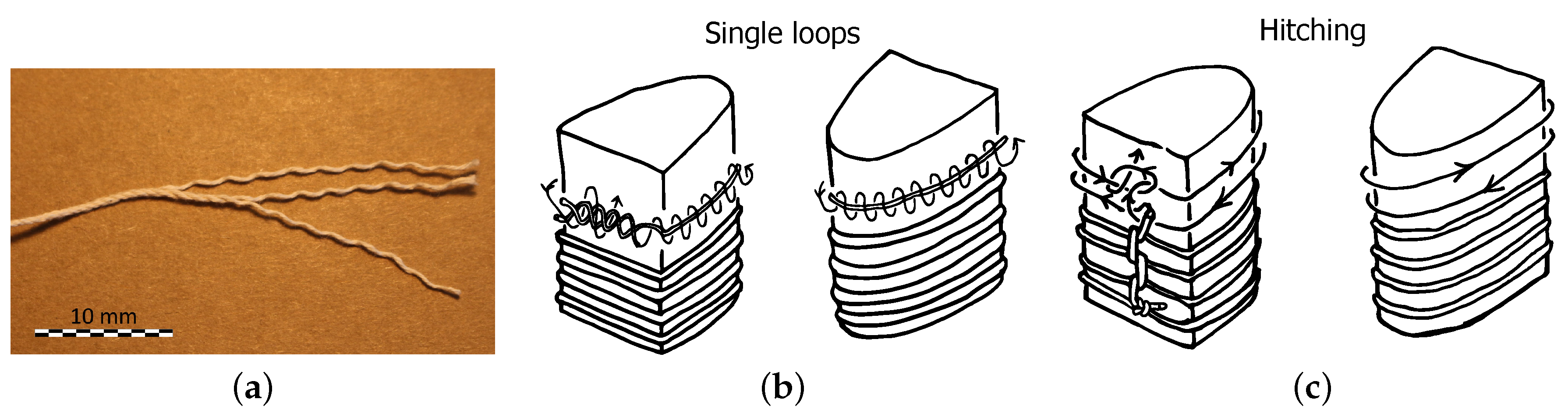
We used two new ways of placing fiber reinforcements on the actuators (Figure 2): separate single loops (from our previous study [20]) and two-directional hitching. We did not embed other strain restricting materials in the actuators to free the bottom layer for length extension. This also simplified the design and reduced fabrication steps.
The single loops of thread (Figure 2b), traditionally called grommets (The Ashley Book of Knots (ABoK) #2864 [36]), are made by taking a single strand of a three-strand thread and winding it around itself twice. Using this method, the knot for closing a loop is 1/3 the size of a knot tied from a three-strand thread, which makes the loop’s thickness more even. This reduces variations in the thickness of the silicone that binds the reinforcements to the actuator. The single loops act only as a radial constraint for the actuator expansion, while letting it freely extend in length. Thus, the resultant actuator motion and forces are defined by other constraints from the actuator’s internal geometry and the assisted finger. This may free the actuator to conform to the shape of the finger, which leads to achieving the wanted assisting motion more effectively. However, making the loops and placing them on the actuator manually take an extremely long amount of time compared to other methods.
The two-directional hitching (Figure 2c), normally used for ringbolt hitching (ABoK #3604 [36]), consists of a series of alternating left and right half-hitches. It combines the benefits of fast manual placement around the actuator and having the fiber crossing itself only on one straight line, while leaving most of it perpendicular to the actuator’s longitudinal axis. We set the self-crossing point to be on the bottom centerline of the actuator. This way, it added a constraint that strengthened flexion, while allowing a slight length extension of the self-crossing point, caused by the loop interval. This also kept the reinforcement distributed symmetrically to minimize effects on the internal structure’s deformation designed to induce the abduction-adduction motion.
By combining these two types of fiber reinforcements in series, it could be possible to control the amounts of length extension and flexion of the internal structure along the actuator’s length and adjust its response to fit the kinematics of the assisted finger.
Based on our previous results [20], we shortened the interval between the reinforcement fibers from 2.0 to 1.5 mm in order to contain the actuators’ deformation better and make them more robust by preventing bulging of the silicone between fibers. However, the actuators required a higher pressure to reach specific bending angles as the amount of deforming silicone between the fibers was reduced.
3. Prototype Fabrication and Evaluation
The functionality of the described actuator and reinforcement designs was validated by fabricating and testing prototypes. Tested reinforcement layouts on the MCP and IP chambers are listed in Table 3. The spaces between chambers and on the actuator root and tip were covered with hitching.
For the combined reinforcement layout, the amounts of single and hitching loops on the MCP chambers were chosen so that hitching covered the part where abduction-adduction and flexion chambers overlapped. Thus, 7.5 mm on each end of the flexion chamber were freed to extend more in length in order to hold the chamber better on top of the assisted joint. For the IP chamber, the amounts of hitching loops were chosen based on the joint flexion ratio described in Equation (1). The three single loops between the joints were approximated to be enough for length extension based on preliminary tests.
Four separate prototypes were fabricated for the tests. In this study, we tested the MCP and IP parts separately without considering their effect on each other, although three of the prototypes had both parts. In this section, we describe how we made the prototypes and how we evaluated and compared them in motion capture and force measurements.
3.1. Fabrication
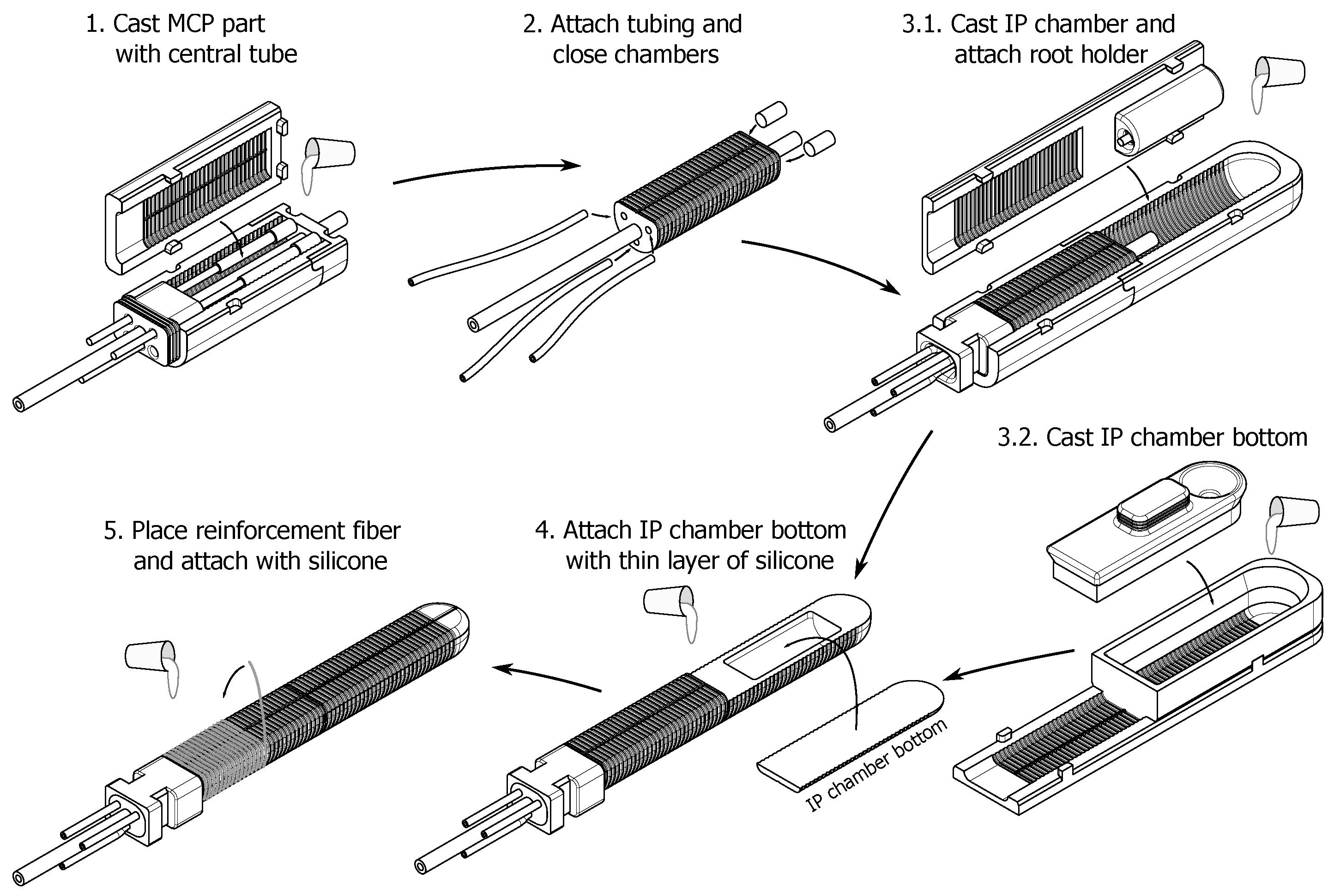
The actuator fabrication flow can be divided roughly into five steps, shown in Figure 3. A modular mold system (CAD files in supplementary materials), 3D printed from polylactic acid (PLA), was used for casting the sections of the main actuator body. A vacuum chamber was used to degas the silicone when casting it.
The actuators were fabricated from a two-part platinum curing silicone, Dragon Skin 10 Slow. Silicone glue, Sil-Poxy, was used for attaching tubing (PDMS) for pressure input, and 0.7 mm-thick three-strand cotton thread (Figure 2a) was used for the fiber reinforcements.
In the end, the fabrication of a full prototype took approximately 27 h, as the silicone was allowed to cure in the molds at room temperature for seven hours after each casting step. This time could be shortened drastically by using an oven to cure the silicone. However, we could not do this, as we used PLA as the mold material. Its glass transition temperature is relatively low, at 60–65 °C, and the molds would have deformed. We only used a heat lamp or heat gun during the last step, when curing the thin layer of silicone for fixing the reinforcements in place.
The single loop reinforcements (Figure 2b) were made by taking a piece of cotton thread, approximately three times the length of actuator circumference, and separating it into three strands. Each strand was then wound on the actuator twice around itself, ending up with three single loops. The ends of each strand were locked in place with a simple reef knot (ABoK #460 [36]).
On the other hand, the two-directional hitching (Figure 2c) was made with a single piece of thread. First, it was locked in place at the root of the actuator with a reef knot. Then, the alternating left and right half-hitches were tied by making left-handed and right-handed loops and tightening them lightly on the actuator, following the guide grooves. The final loop was locked in place by making a half-hitch with the end of the thread around itself.
3.2. Dummy Finger
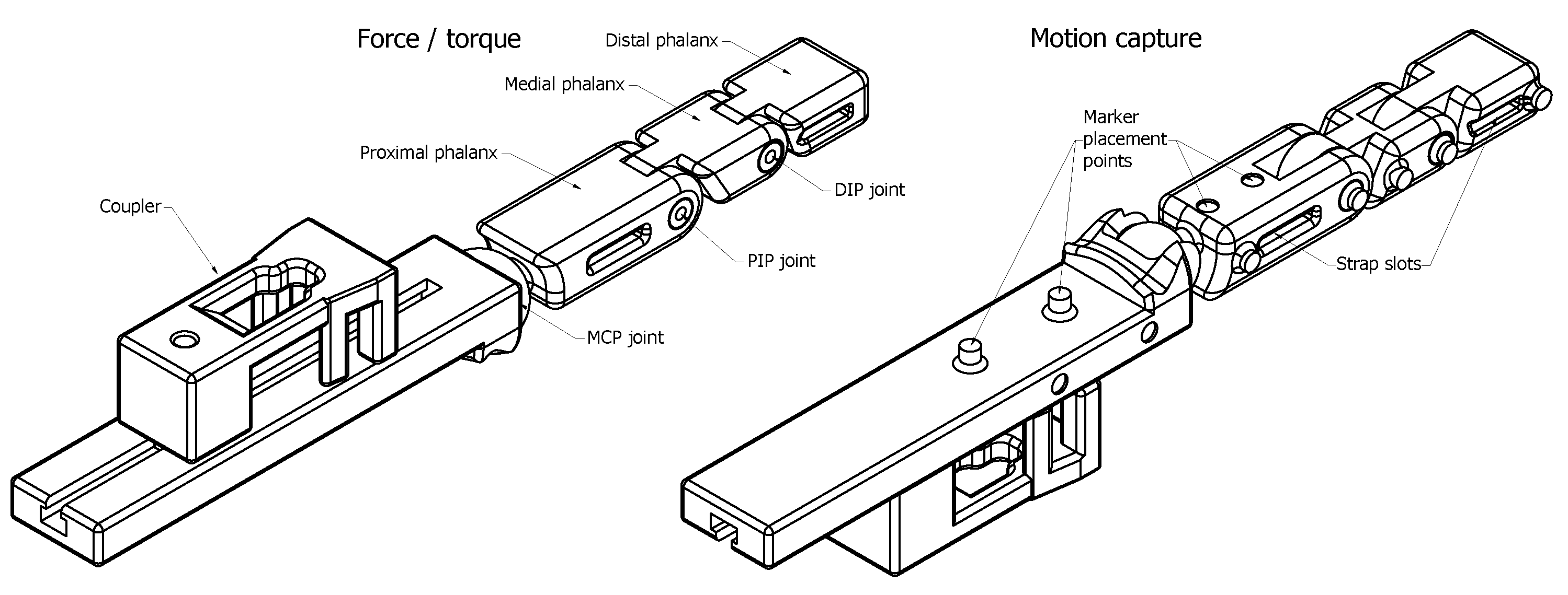
The actuators should be attached to a finger to have a realistic view of how well they perform. However, making accurate measurements of the motion trajectories and torques of a human finger is challenging due to the soft tissues and other factors. Thus, we designed and manufactured an anthropomorphic dummy finger (Figure 4) that worked as a test bench for measuring how the reinforcements affected the coupled motion and joint angles, and the torques that the actuators could apply to the finger joints. The MCP joint was a 2-DoF ball joint, and the IP joints were 1-DoF pin joints. As with the actuators, the dummy finger’s dimensions (Table 4) were based on the collaborating patient’s index finger.
Two versions of the finger were made, one for force and torque measurements and one for motion capture (Figure 4). The fingers were 3D printed from PLA. The one for torque measurements had holes through the IP joint centers for wire attachment, while 3-mm reflective markers were attached to the one for motion capture. CAD files and further details for both dummy fingers are available online at the Thingiverse website [37].
3.3. Motion Capture Measurements
For evaluating the prototypes’ response, we connected them to the dummy finger and measured the finger’s motion with a motion capture system.
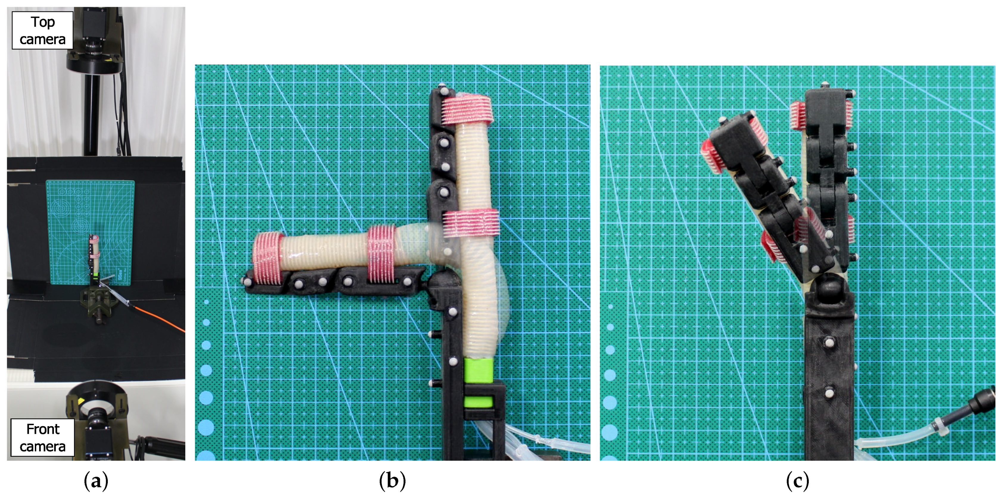
The motion capture measurements were made in 1D, meaning that only one camera for each plane of motion was used. For the flexion measurements, one camera was set on the side of the test setup, perpendicular to it. For abduction-adduction, two cameras were used, one on top of the test setup and another in front of it. Figure 5 shows the setup.
Flexion angle measurements were done at 0–225-kPa pressures, with 25-kPa intervals, repeated three times, and the average was calculated. Abduction-adduction measurements were done in the same manner, with the exception of maximum pressure being determined from when the joint reached its 30° RoM limit.
3.4. Joint Torque and Fingertip Force Measurements
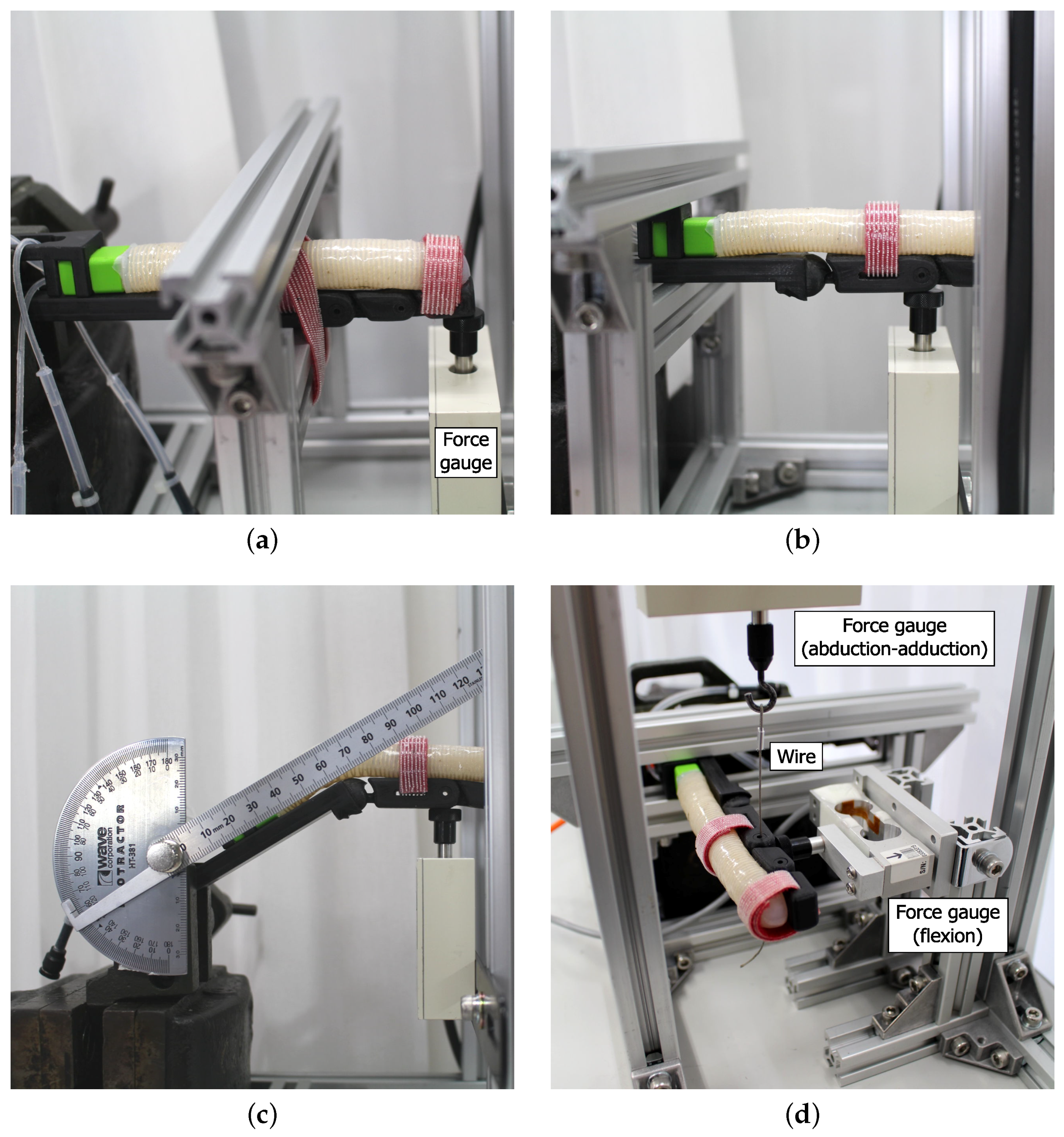
The goal of the torque measurements was to evaluate how well the different reinforcement layouts could transfer the actuator’s deformation to forces in the wanted directions and, thus, apply the required torques on a finger. The torque measurement setups are shown in Figure 6.
For the MCP joint, the actuators were measured in flexion-extension and the abduction-adduction direction. The flexion measurements were done at 0°, 30° and 60° joint angles by placing the force gauge under the finger at the PIP joint center (Figure 6b). Two force gauges were used for abduction-adduction. The finger was suspended from its PIP joint with a steel wire attached to one gauge (Figure 6d). The secondary gauge was placed on the side, under the PIP joint, to measure flexion forces. The dummy finger’s proximal phalanx length, from the joint center to the measurement point, was mm. The force gauges were always kept at a right angle to the finger. Thus, the torque at the joint was:
The IP joint flexion measurements were done in a similar fashion as the MCP flexion with the difference of the finger being supported at the proximal phalanx and the measurement being done at the fingertip (Figure 6a). However, as the actuator was controlling both IP joints at the same time, the results cannot be considered as a simple joint torque. Thus, we analyzed them as fingertip force.
The force measurements were done in 0–225-kPa pressure range, with 50-kPa intervals. For MCP joint flexion torque, each measurement was repeated three times, and the average was calculated. The minimum pressures for the angled flexion measurements were different for each prototype. It was defined as the pressure at which the actuators reached the 30° or 60° target angle. For fingertip force in IP joint flexion, the measurements were repeated six times, and the average was calculated. For abduction-adduction, the measurements were repeated six times to the left and right, and the average was calculated as a combination of all 12 measurements. This was done to compensate for any imbalances caused by hand-made fabrication between the actuators’ left and right side.
4. Results
In this section, we present the results for the motion capture and force measurements. Full set of numerical data and more photos of the experiments are available as supplementary materials.
4.1. MCP Joint Flexion
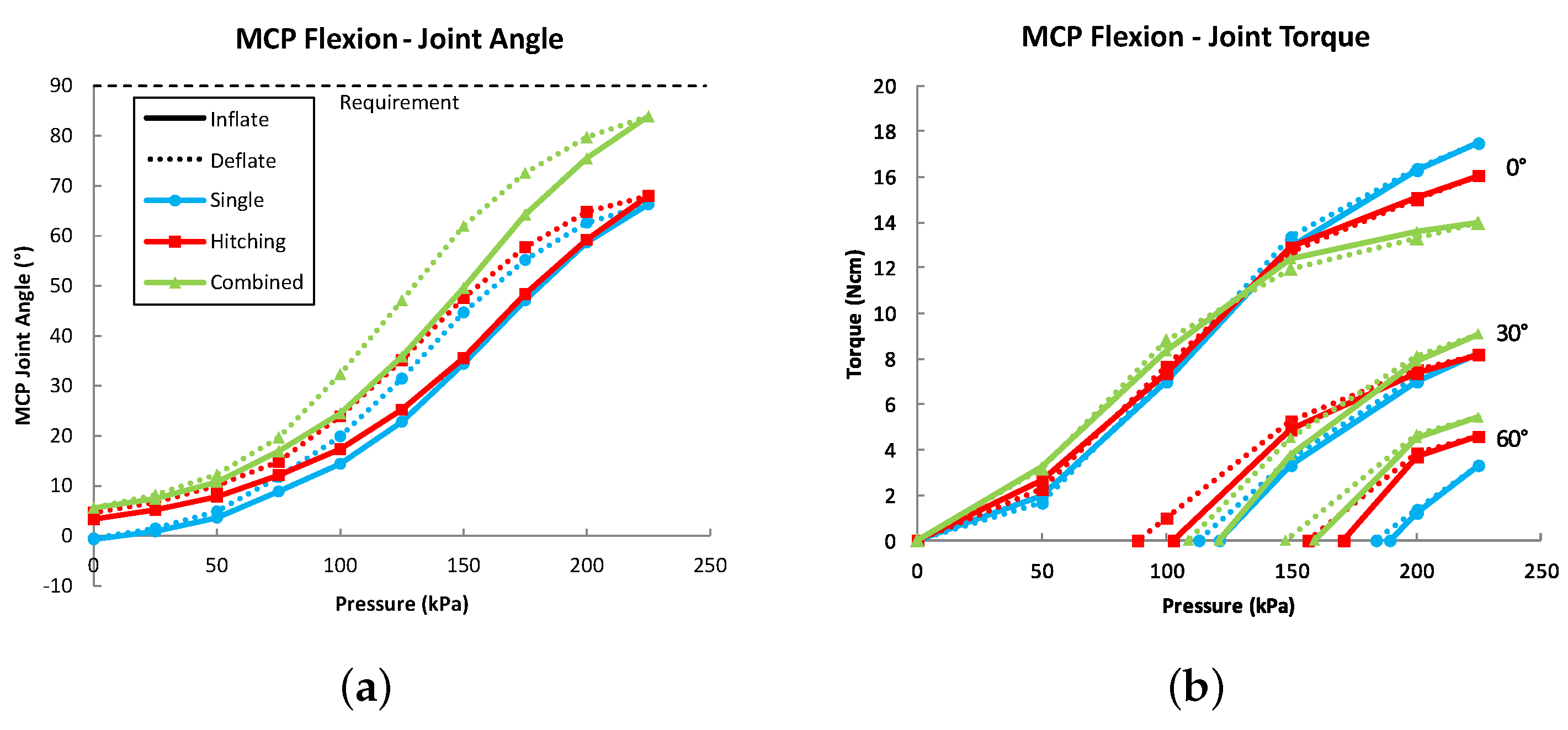
The measurement results for MCP joint flexion angles and torques are presented in Figure 7.
The combined reinforcement layout required lower pressures to flex the dummy finger’s MCP joint than the other layouts, which had a similar response to each other.
The single-loop layout gave the highest maximum torque output at 0°. However, the combination layout performed better at 30° and 60°. Furthermore, in agreement with the motion capture results, the combination layout reached 60° at a lower pressure than the other layouts.
4.2. MCP Joint Abduction-Adduction
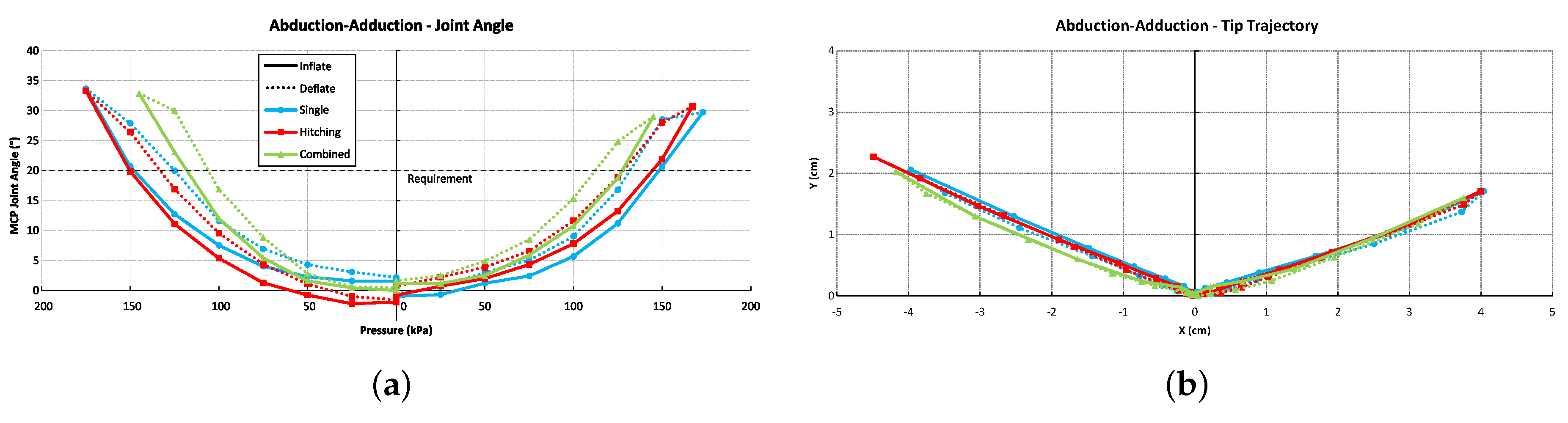
The motion capture results showing the MCP joint abduction-adduction angles and fingertip deviation from the top perspective are presented in Figure 8.
The combined reinforcement layout needed a lower pressure to reach the maximum angle (30°) of the dummy joint.
Forwards deviation during the motion did not change much between the different layouts. They all moved forwards approximately 2 cm, 50% of the sideways motion range. The origin was set to the location of the fingertip at the beginning of motion. This can be seen as a slightly longer trajectory to the left than to the right, as the fingertip started its motion slightly off center in the measurements.
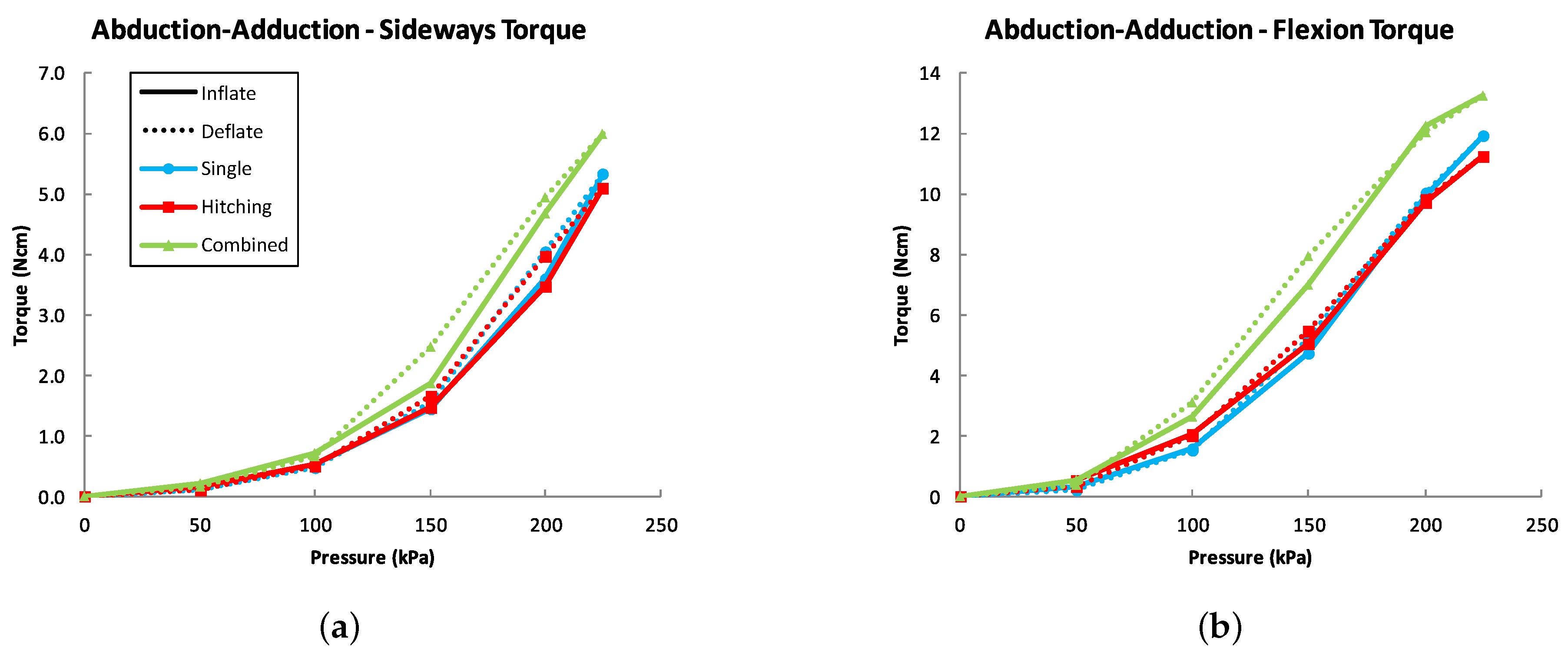
Measurement results showing MCP joint torques for abduction-adduction are presented in Figure 9, showing a combined average of results to the left and right.
All the reinforcement layouts led to a forwards bending torque (Figure 9b), which agrees with the motion capture results of the fingertip forwards motion (Figure 8b). The response was similar with single loops and hitching, while the combined layout produced a higher torque to both sideways and forwards directions.
4.3. IP Joint Flexion
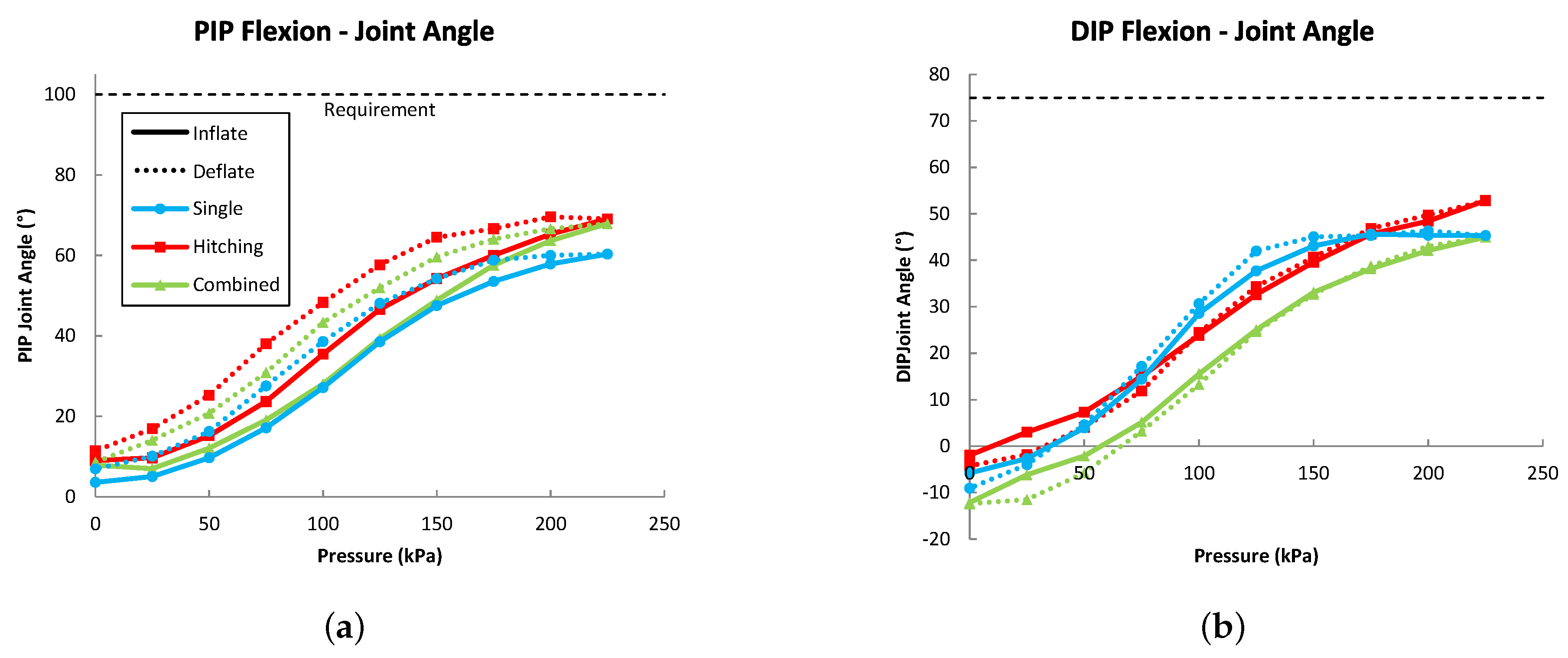
The motion capture results showing the dummy finger’s IP joint angles in flexion are presented in Figure 10.
For PIP joint, hitching and combined layouts gave a similar result with maximum flexion angles of 69° (69% of normal finger RoM) and 68° (68%), respectively. For single loops, the result was almost 10° lower at 60° (60%). For the DIP joint, hitching reached a maximum angle of 53° (71%), while single loops and combined both achieved 45° (60%). Notably, the single loop prototype’s response started fastest, but leveled out at 45° by 175 kPa, while the other two had a straighter slope.
The IP joints’ bending ratio (Equation (1)), approximating from the final joint angles, was 0.75 for single loops, 0.76 for hitching and 0.66 for the combined layout. However, the single loop prototype’s DIP joint angle leveled out by 175 kPa. At 175 kPa, the bending ratio was 0.85 for single loops, but again 0.76 for hitching and 0.66 for the combined layout.
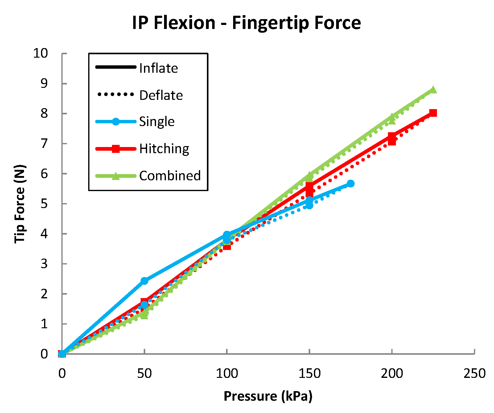
Finally, the fingertip forces for IP joint flexion are presented in Figure 11.
While both the hitching and combined layouts’ response started similarly, the combined layout reached a higher maximum fingertip force, with a difference of 0.86 N. The single-loop layout could be inflated only to 175 kPa, as its length deformation became too large. It reached an average maximum force output of 5.67 N.
5. Discussion
Interestingly, both the single loops and hitching by themselves had a similar effect on the actuators’ response (Figure 7, Figure 8 and Figure 9). The single loops, while allowing the internal structure to deform more lengthwise to push the finger forward, did not direct the deformation into flexion as much as expected. On the other hand, the hitching by itself did not provide enough length extension, causing the chambers to lag behind the joint centers. This caused the actuator to clamp itself on the joints, preventing them from flexing.
The combined reinforcement layout performed generally better than the single loops or hitching alone. The combination of the two modes of restriction allowed the body to extend in length in the parts covered in single loops to keep the inflated chamber on top of the joint center, while strengthening bending for the parts that were covered with hitching.
None of the actuator configurations reached the full RoM goals that we set based on normal finger RoMs (Table 1). However, all configurations passed limits for average functional flexion RoMs, which are commonly used to evaluate the performance of motion assist gloves [8,9]. These RoMs are 61° (MCP), 60° (PIP) and 39° (DIP), reported by Hume et al. [38]. This means that our current prototypes could be used for assisting most daily life grasping tasks (e.g., holding a telephone or a can) that do not require reaching full RoMs of the joints (e.g., holding a toothbrush).
With the current results, however, we cannot say whether the tested actuators could be able to reach the normal full joint angles, if inflated further. The actuator structures themselves can endure higher pressures, but the PDMS input tubing we used acted as a bottleneck for the maximum pressure, as it could only withstand pressures below 250 kPa. Still, as mentioned by Krishnan et al. [27], all fiber-reinforced actuator configurations will eventually reach a locked state when inflated to a high enough pressure, preventing them from deforming further. The slight S-shape that can be observed in all the flexion angle measurement curves seems to indicate that the actuators were approaching this limit. This cannot be seen in the abduction-adduction graphs (Figure 8a and Figure 9a), as the RoM was limited to 30°.
In the following sections, we discuss the results for MCP and IP joints separately, as the internal actuator structure was different for the two parts.
5.1. MCP Joint Assist
For MCP joint flexion, the combined reinforcement layout provided the widest RoM of 84° (93% of normal joint RoM (Table 1)), while single loops and hitching reached 66° (74%) and 68° (76%), respectively. As a comparison, Yap et al. [14] achieved an MCP joint flexion angle of 79.2 ± 4.1° (88%), when assisting a passive hand with their soft pneumatic glove.
The combined layout prototype also continued applying torque to the joint better at higher flexion angles. These effects may be due to the single loops allowing the internal structure at the ends of the flexion chamber to extend in length, while hitching caused its center to bend. This kept the strongly bending part of the chamber on top of the joint. Furthermore, during the torque measurements, we observed that constraining the finger from moving did not cause any of the actuators to slip off or twist it. This showed that all presented reinforcements combined with the internal structure could keep their resultant deformation forces perpendicular to the finger throughout the tested pressure range without interference between them causing sideways motion or axial twisting.
For abduction-adduction, all layouts reached the 30° dummy joint limit (Figure 8). Forwards deviation during abduction-adduction was always observed in the same magnitude for all prototypes (Figure 8b). While the central input tubing for the IP joint chamber limited the MCP part length expansion above the abduction-adduction chambers, it could not oppose the much stronger constraints set by the finger. However, this deviation is small, when comparing it to the overall motion range of the finger, and could be allowed in a practical application for motion assist. Furthermore, changing the central tube’s material properties could be used to reduce the interference from this constraint by strengthening the actuator’s ability to oppose it.
Comparing to the actuator prototypes in our previous study [20], the current actuators’ torque output reached similar values for flexion at 0°. However, for the angled flexion measurements, the response was clearly weaker. This was probably due to the tighter reinforcement interval and the flexion chamber being much more restricted by the silicone and central input tube under it. However, pressures at which the actuators reached 30° and 60° were similar to the previous results. The abduction-adduction torque values were between the weakest and strongest prototypes from the previous study. This was expected, as the abduction-adduction chambers were made shorter than the previously strongest prototype and longer than the weaker ones.
5.2. IP Joint Assist
For the IP joint flexion, the prototypes could not reach the set normal finger RoMs of 100° and 75° for the PIP and DIP joint, respectively. The single loops prototype reached 60% for both joints. With hitching, the results for both joints were 70% of the requirement, while combined layout could obtain 68% and 60% for PIP and DIP joint, respectively. For comparison, Yap et al. [14] reached passive hand assist flexion angles of 84.3 ± 6.8° (84%) for PIP and 46.4 ± 9.9° (62%) for the DIP joint (bending ratio of 0.55). Thus, at least with the current geometry and limited range of tested parameters combined with the limited maximum pressure, the joints cannot reach the required flexion angles. We believe the full normal IP joint RoMs with these reinforcements could be achieved by improving the internal geometry (e.g., relative wall thicknesses) and the materials used based on established methods [17,22,23,24,25,26].
Interestingly, comparing the summed maximum joint angles (105° for single loops, 122° for hitching and 113° for combined), the combined layout’s result was between the other two, but it provided the highest maximum fingertip force. This was probably due to the single loops in the middle making the prototype transfer the forces more effectively to the dummy finger, while it was constrained to a straight posture in the force measurement. The single loop prototype’s weakness was clearly due to the excessive length extension, which caused its response to deteriorate at a relatively low pressure.
Finally, the relative bending ratios (Equation (1)) of 0.75–0.85 for single loops, 0.76 for hitching and 0.66 for the combined layout show that by combining the two types of reinforcement in different ratios, it is possible to adjust the relative IP joint bending rate. However, the relationship was not straightforward between the bending ratio and the relative amount of hitching loops for each joint. Factors affecting this may have been, e.g., the amount of length extension the single loops provided between the joints and/or the dummy joint geometry, as they had different diameters to imitate the dimensions of a real finger. Thus, further in-depth investigation is needed in order to determine the exact connections between these variables.
5.3. Future Work
In this study, we did not test in detail the effects of changing the amount of single loops in the combined reinforcement layout, or different chamber alignments and dimensions. Optimizing these essential parameters could be best done through simulations using finite element analysis. This would hasten the design process and enable patient-specific tailor-made actuator fabrication.
We left out the consideration of extension, as we saw its implementation in a rehabilitation device to be mutually exclusive with flexion. However, to accommodate the different patients’ needs, we see the combination of extension and abduction-adduction worth studying in the future.
Furthermore, the thumb plays an important role in daily life manipulation tasks, and its rehabilitation is essential for full recovery. We believe that the presented actuator structure and reinforcement layouts could also be modified for thumb motion assistance by providing multidirectional control of the thumb’s carpometacarpal joint. However, a major challenge is to couple the actuator’s motion effectively to the first metacarpal bone, as it is surrounded by a thick layer of soft tissue.
Finally, patients with hand disabilities often have abnormal stiffness in their joints, which makes it an essential part of the dynamics of hand rehabilitation. Thus, a dummy hand system could be augmented with adjustable stiffness to provide a realistic test bench for evaluating the actuators’ ability to counter it.
6. Conclusions
In this study, we proposed two new ways of placing the reinforcements around fiber-reinforced elastomer actuators: single loops and two-directional hitching. Our goal was to use them and their combination on a new design of a multi-chamber actuator structure to enable full finger motion assist, while suppressing interference between its structurally-connected flexion and abduction-adduction functions. The fiber reinforcements’ effects were evaluated by producing prototypes, connecting them to a dummy finger and measuring the resultant joint motion and force output.
Based on our results, we can infer that the introduced fiber reinforcement layouts could be used in combination with a multi-chamber structure to adjust actuator response to fit the assisted fingers’ kinematics, while reducing unwanted flexion during abduction-adduction and sideways deviation and twisting during flexion.
Thus, we took a step closer to including abduction-adduction as a viable function for rehabilitation gloves to enable full motion assist of the hand. Furthermore, we believe our findings can be applied in the field of soft robotics in a wide variety of ways and are not only specific to the application of rehabilitation and power-assist gloves.
Supplementary Materials
Supplementary materials including all the used measurement data, additional photos of experiments and prototypes, and CAD files for the mold are available online at https://www.mdpi.com/2076-0825/7/2/31/s1.
Author Contributions
T.V.J.T. was the main author of the manuscript and conducted the design, fabrication and testing of the presented prototypes. J.F.-V. assisted in data analysis and their presentation and participated in revising the manuscript’s contents. W.Y. was the main supervisor and advisor of the work and contributed to the manuscript by reviewing and revising its contents.
Funding
This work was supported by JSPS Grant-in-Aid for Scientific Research (B) 17H02129.
Acknowledgments
We would like to thank Kouki Shiota for technical support in the project and especially for making the illustrations for Figure 2. We are also grateful to Jose Gomez-Tames, Shaoying Huang, Mika Kontto and İlker Sönmezışık for providing valuable comments on the contents of the manuscript. Finally, we would also like to thank Kornkanok Tripanpitak for providing invaluable insight about physical therapy.
Conflicts of Interest
The authors declare no conflict of interest. The funding sponsors had no role in the design of the study; in the collection, analyses or interpretation of data; in the writing of the manuscript; nor in the decision to publish the results.
Abbreviations
The following abbreviations are used in this manuscript:
| ABoK | The Ashley Book of Knots |
| DoF | Degree of Freedom |
| IP | Interphalangeal (joint) |
| DIP | Distal interphalangeal (joint) |
| PIP | Proximal interphalangeal (joint) |
| MCP | Metacarpophalangeal (joint) |
References
- Abidi, H.; Cianchetti, M. On Intrinsic Safety of Soft Robots. Front. Robot. AI 2017, 4, 5. [Google Scholar] [CrossRef]
- Chu, C.Y.; Patterson, R.M. Soft robotic devices for hand rehabilitation and assistance: A narrative review. J. NeuroEng. Rehabil. 2018, 15, 9. [Google Scholar] [CrossRef] [PubMed]
- Polygerinos, P.; Correll, N.; Morin, S.A.; Mosadegh, B.; Onal, C.D.; Petersen, K.; Cianchetti, M.; Tolley, M.T.; Shepherd, R.F. Soft Robotics: Review of Fluid-Driven Intrinsically Soft Devices; Manufacturing, Sensing, Control and Applications in Human-Robot Interaction. Adv. Eng. Mater. 2017, 19. [Google Scholar] [CrossRef]
- Rus, D.; Tolley, M.T. Design, fabrication and control of soft robots. Nature 2015, 521, 467–475. [Google Scholar] [CrossRef] [PubMed] [Green Version]
- Maciejasz, P.; Eschweiler, J.; Gerlach-Hahn, K.; Jansen-Troy, A.; Leonhardt, S. A survey on robotic devices for upper limb rehabilitation. J. NeuroEng. Rehabil. 2014, 11, 3. [Google Scholar] [CrossRef] [PubMed] [Green Version]
- Hunter, S.M.; Crome, P. Hand function and stroke. Rev. Clin. Gerontol. 2002, 12, 68–81. [Google Scholar] [CrossRef]
- Krakauer, J.W. The applicability of motor learning to neurorehabilitation. In Oxford Textbook of Neurorehabilitation; Dietz, V., Ward, N., Eds.; Oxford University Press: Oxford, UK, 2015; pp. 55–64. [Google Scholar]
- Yap, H.K.; Lim, J.H.; Nasrallah, F.; Yeow, C.H. Design and Preliminary Feasibility Study of a Soft Robotic Glove for Hand Function Assistance in Stroke Survivors. Front. Neurosci. 2017, 11, 547. [Google Scholar] [CrossRef] [PubMed]
- Polygerinos, P.; Wang, Z.; Galloway, K.C.; Wood, R.J.; Walsh, C.J. Soft robotic glove for combined assistance and at-home rehabilitation. Robot. Auton. Syst. 2015, 73, 135–143. [Google Scholar] [CrossRef] [Green Version]
- Pataky, T.C.; Latash, M.L.; Zatsiorsky, V.M. Multifinger Ab- and Adduction Strength and Coordination. J. Hand Ther. 2008, 21, 377–385. [Google Scholar] [CrossRef] [PubMed] [Green Version]
- Dovat, L.; Lambercy, O.; Gassert, R.; Maeder, T.; Milner, T.; Leong, T.C.; Burdet, E. HandCARE: A Cable-actuated Rehabilitation System To Train Hand Function After Stroke. IEEE Trans. Neural Syst. Rehabil. Eng. 2008, 16, 582–591. [Google Scholar] [CrossRef] [PubMed]
- Kadowaki, Y.; Noritsugu, T.; Takaiwa, M.; Sasaki, D.; Kato, M. Development of soft power-assist glove and control based on human intent. J. Robot. Mechatron. 2011, 23, 281–291. [Google Scholar] [CrossRef]
- Yap, H.K.; Lim, J.H.; Nasrallah, F.; Goh, J.C.H.; Yeow, C.H. A soft exoskeleton for hand assistive and rehabilitation application using pneumatic actuators with variable stiffness. In Proceedings of the 2015 IEEE International Conference on Robotics and Automation (ICRA), Seattle, WA, USA, 26–30 May 2015; pp. 4967–4972. [Google Scholar]
- Yap, H.K.; Kamaldin, N.; Lim, J.H.; Nasrallah, F.; Goh, J.C.H.; Yeow, C.H. A Magnetic Resonance Compatible Soft Wearable Robotic Glove for Hand Rehabilitation and Brain Imaging. IEEE Trans. Neural Syst. Rehabil. Eng. 2017, 25, 782–793. [Google Scholar] [CrossRef] [PubMed]
- Chua, M.C.H.; Hoon, L.J.; Yeow, R.C.H. Design and evaluation of Rheumatoid Arthritis rehabilitative Device (RARD) for laterally bent fingers. In Proceedings of the 2016 6th IEEE International Conference on Biomedical Robotics and Biomechatronics (BioRob), Singapore, Singapore, 26–29 June 2016; pp. 839–843. [Google Scholar]
- Yun, S.S.; Kang, B.B.; Cho, K.J. Exo-Glove PM: An Easily Customizable Modularized Pneumatic Assistive Glove. IEEE Robot. Autom. Lett. 2017, 2, 1725–1732. [Google Scholar] [CrossRef]
- Deimel, R.; Brock, O. A novel type of compliant and underactuated robotic hand for dexterous grasping. Int. J. Robot. Res. 2016, 35, 161–185. [Google Scholar] [CrossRef]
- Gerboni, G.; Ranzani, T.; Diodato, A.; Ciuti, G.; Cianchetti, M.; Menciassi, A. Modular soft mechatronic manipulator for minimally invasive surgery (MIS): Overall architecture and development of a fully integrated soft module. Meccanica 2015, 50, 2865–2878. [Google Scholar] [CrossRef]
- Park, Y.L.; Santos, J.; Galloway, K.G.; Goldfield, E.C.; Wood, R.J. A soft wearable robotic device for active knee motions using flat pneumatic artificial muscles. In Proceedings of the 2014 IEEE International Conference on Robotics and Automation (ICRA), Hong Kong, China, 31 May–7 June 2014; pp. 4805–4810. [Google Scholar]
- Tarvainen, T.V.J.; Yu, W. Pneumatic Multi-Pocket Elastomer Actuators for Metacarpophalangeal Joint Flexion and Abduction-Adduction. Actuators 2017, 6, 27. [Google Scholar] [CrossRef]
- Yap, H.K.; Khin, P.M.; Koh, T.H.; Sun, Y.; Liang, X.; Lim, J.H.; Yeow, C.H. A Fully Fabric-Based Bidirectional Soft Robotic Glove for Assistance and Rehabilitation of Hand Impaired Patients. IEEE Robot. Autom. Lett. 2017, 2, 1383–1390. [Google Scholar] [CrossRef]
- Guiducci, L.; Weaver, J.C.; Bréchet, Y.J.M.; Fratzl, P.; Dunlop, J.W.C. The Geometric Design and Fabrication of Actuating Cellular Structures. Adv. Mater. Interfaces 2015, 2. [Google Scholar] [CrossRef]
- Ilievski, F.; Mazzeo, A.D.; Shepherd, R.F.; Chen, X.; Whitesides, G.M. Soft Robotics for Chemists. Angew. Chem. Int. Ed. 2011, 50, 1890–1895. [Google Scholar] [CrossRef] [PubMed]
- Marchese, A.D.; Katzschmann, R.K.; Rus, D. A Recipe for Soft Fluidic Elastomer Robots. Soft Robot. 2015, 2, 7–25. [Google Scholar] [CrossRef] [PubMed]
- Marchese, A.D.; Rus, D. Design, kinematics, and control of a soft spatial fluidic elastomer manipulator. Int. J. Robot. Res. 2015, 35, 840–869. [Google Scholar] [CrossRef]
- Connolly, F.; Walsh, C.J.; Bertoldi, K. Automatic design of fiber-reinforced soft actuators for trajectory matching. Proc. Natl. Acad. Sci. USA 2017, 114, 51–56. [Google Scholar] [CrossRef] [PubMed]
- Krishnan, G.; Bishop-Moser, J.; Kim, C.; Kota, S. Evaluating Mobility Behavior of Fluid Filled Fiber-Reinforced Elastomeric Enclosures. In Proceedings of the 36th Mechanisms and Robotics Conference ASME, Chicago, IL, USA, 12–15 August 2012; Volume 4. Pts A and B. [Google Scholar]
- Eppner, C.; Deimel, R.; Álvarez-Ruiz, J.; Maertens, M.; Brock, O. Exploitation of environmental constraints in human and robotic grasping. Int. J. Robot. Res. 2015, 34, 1021–1038. [Google Scholar] [CrossRef] [Green Version]
- Galloway, K.C.; Polygerinos, P.; Walsh, C.J.; Wood, R.J. Mechanically programmable bend radius for fiber-reinforced soft actuators. In Proceedings of the 2013 16th International Conference on Advanced Robotics (ICAR), Montevideo, Uruguay, 25–29 November 2013. [Google Scholar]
- Nguyen, P.H.; Sridar, S.; Zhang, W.; Polygerinos, P. Design and control of a 3-chambered fiber reinforced soft actuator with off-the-shelf stretch sensors. Int. J. Intell. Robot. Appl. 2017, 1, 342–351. [Google Scholar] [CrossRef]
- Hahn, P.; Krimmer, H.; Hradetzky, A.; Lanz, U. Quantitative Analysis of the Linkage between the interphalangeal Joints of the Index Finger: An in vivo study. J. Hand Surg. 1995, 20, 696–699. [Google Scholar] [CrossRef]
- Leijnse, J.; Quesada, P.; Spoor, C. Kinematic evaluation of the finger’s interphalangeal joints coupling mechanism—variability, flexion–extension differences, triggers, locking swanneck deformities, anthropometric correlations. J. Biomech. 2010, 43, 2381–2393. [Google Scholar] [CrossRef] [PubMed]
- Montgomery, J. Daniels and Worthingham’s Muscle Testing, 8th ed.; Saunders Elsevier: St. Louis, MO, USA, 2007. [Google Scholar]
- Kawasaki, H.; Kimura, H.; Ito, S.; Nishimoto, Y.; Hayashi, H.; Sakaeda, H. Hand Rehabilitation Support System Based on Self-Motion Control, with a Clinical Case Report. In Proceedings of the 2006 World Automation Congress, Budapest, Hungary, 24–26 July 2006; pp. 1–6. [Google Scholar]
- Wang, Z.; Polygerinos, P.; Overvelde, J.T.B.; Galloway, K.C.; Bertoldi, K.; Walsh, C.J. Interaction Forces of Soft Fiber Reinforced Bending Actuators. IEEE/ASME Trans. Mechatron. 2017, 22, 717–727. [Google Scholar] [CrossRef]
- Ashley, C.W. The Ashley Book of Knots; Faber and Faber: London, UK, 1993. [Google Scholar]
- Tarvainen, T.V.J. Thingiverse Thing: 2790972, Dummy Finger Testbed for Soft Actuators. Available online: https://www.thingiverse.com/thing:2790972 (accessed on 17 June 2018).
- Hume, M.C.; Gellman, H.; McKellop, H.; Brumfield, R.H., Jr. Functional range of motion of the joints of the hand. J. Hand Surg. 1990, 15, 240–243. [Google Scholar] [CrossRef]
Figure 1.
CAD drawings of the designed actuator’s (a) overall structure and details of the (b) proximal MCP chambers and (c) distal IP chamber.
Figure 1.
CAD drawings of the designed actuator’s (a) overall structure and details of the (b) proximal MCP chambers and (c) distal IP chamber.

Figure 2.
Studied types of fiber reinforcements. (a) Structure of the 0.7-mm three-strand cotton thread used for reinforcements; (b) Separate single loops had a single strand of the thread wound around itself twice. It was locked in place by tying the strand’s ends together with a small knot; (c) Two-directional hitching was made by tying consecutive left and right half-hitches with the three-strand thread around the actuator. The first and last loop were locked in place with a reef knot or a hitch. The combined reinforcement layout was made by placing both single loops and hitching on the actuator in series. Illustrations courtesy of Kouki Shiota.

Figure 3.
Actuator fabrication flow. (1) The MCP part is cast first; and (2) input tubing is attached to it. Abduction-adduction chambers are plugged with pieces of 4-mm tubing, and the flexion chamber is closed with glue. (3.1) The MCP part is placed in the mold, and the IP chamber’s top is cast to merge with it. The root holder can also be attached at this point. (3.2) The IP chamber’s bottom is cast simultaneously with the IP chamber, in a separate mold. (4) The 2-mm thick IP chamber bottom is then attached to close the chamber. (5) Finally, reinforcements are placed on the actuator in the wanted layout and attached with a thin layer of silicone.

Figure 4.
CAD drawings of dummy fingers for force and torque measurements (Left) and motion capture (Right). Dimensions for the fingers are presented in Table 4. The models are available online at the Thingiverse website [37].

Figure 5.
Motion capture measurement setup, showing the prototype with the combined reinforcement layout. (a) Overview with one camera in front and one on top of the test bench; (b) MCP flexion setup at 0 kPa and 225 kPa; (c) abduction-adduction setup at 0 kPa and 145 kPa (30°).
Figure 5.
Motion capture measurement setup, showing the prototype with the combined reinforcement layout. (a) Overview with one camera in front and one on top of the test bench; (b) MCP flexion setup at 0 kPa and 225 kPa; (c) abduction-adduction setup at 0 kPa and 145 kPa (30°).

Figure 6.
Torque measurement setups for: (a) IP joint flexion; (b) MCP joint flexion at 0°; (c) MCP joint flexion at 30°; and (d) MCP joint abduction-adduction to the right.
Figure 6.
Torque measurement setups for: (a) IP joint flexion; (b) MCP joint flexion at 0°; (c) MCP joint flexion at 30°; and (d) MCP joint abduction-adduction to the right.

Figure 7.
MCP joint flexion measurement results for (a) joint angle and (b) torque.

Figure 8.
Motion capture measurement results for MCP joint abduction-adduction to the left and right, showing (a) the joint angle and (b) fingertip trajectory from above.
Figure 8.
Motion capture measurement results for MCP joint abduction-adduction to the left and right, showing (a) the joint angle and (b) fingertip trajectory from above.

Figure 9.
Torque measurement results for MCP joint abduction-adduction in (a) sideways and (b) flexion directions. The result is the average of measurements to the left and to the right. Note that the scale for flexion torque is double that of abduction-adduction.
Figure 9.
Torque measurement results for MCP joint abduction-adduction in (a) sideways and (b) flexion directions. The result is the average of measurements to the left and to the right. Note that the scale for flexion torque is double that of abduction-adduction.

Figure 10.
Motion capture measurement results for flexion of (a) PIP joint and (b) DIP joint.

Figure 11.
Fingertip forces for IP joint flexion.


Table 1.
Normal ranges of motion for the finger joints and corresponding actuator requirements. RoM, range of motion.
Table 1.
Normal ranges of motion for the finger joints and corresponding actuator requirements. RoM, range of motion.
| Joint | Motion | Normal Joint RoM (°) | Requirement (°) |
|---|---|---|---|
| MCP | Flexion/Extension | 90/45 * | 90/0 |
| MCP | Abduction/Adduction | 20/20 * | 20/20 |
| PIP | Flexion | 104 ** | 100 |
| DIP | Flexion | 74 ** | 75 |
Table 2.
Actuator torque requirements.
| Joint | Motion | Minimum Torque Range (Ncm) * | Acceptable Assisting Torque (Ncm) ** |
|---|---|---|---|
| MCP | Flexion | 0°: 15.4 ... 18.0 30°: 10.0 ... 16.6 60°: 5.2 ... 9.8 | 29.3 |
| MCP | Abduction-Adduction | 0°: 3.0 ... 9.2 | 16.7 |
| IP | Flexion | N/A | 19.7 |
Table 3.
Tested reinforcement layouts on the MCP (l = 35 mm) and IP (l = 32.5 mm) chambers.
| Reinforcement Type | MCP | IP |
|---|---|---|
| Single loops | 24 s | 23 s |
| Two-directional hitching | 24 h | 23 h |
| Combined | 5 s–14 h–5 s | 12 h–3 s–8 h |
s = single loops; h = hitching loops.
Table 4.
Dimensions of the dummy finger and its range of motion.
| Proximal Phalanx | Medial Phalanx | Distal Phalanx | |
|---|---|---|---|
| Length (mm) | 37 | 20 | 18 (+5) * |
| Width (mm) | 16 | 16 | 16 |
| Height (mm) | 12 | 10 | 10 |
| MCP | PIP | DIP | |
| Joint radius (mm) | 8 | 6 | 5 |
| RoM (flexion) (°) | 120 | 120 | 110 |
| RoM (abduction-adduction) (°) | 30 | N/A | N/A |
* 5 mm added for the strap slot.
© 2018 by the authors. Licensee MDPI, Basel, Switzerland. This article is an open access article distributed under the terms and conditions of the Creative Commons Attribution (CC BY) license (http://creativecommons.org/licenses/by/4.0/).
Share and Cite
MDPI and ACS Style
Tarvainen, T.V.J.; Fernandez-Vargas, J.; Yu, W. New Layouts of Fiber Reinforcements to Enable Full Finger Motion Assist with Pneumatic Multi-Chamber Elastomer Actuators. Actuators 2018, 7, 31. https://doi.org/10.3390/act7020031
AMA Style
Tarvainen TVJ, Fernandez-Vargas J, Yu W. New Layouts of Fiber Reinforcements to Enable Full Finger Motion Assist with Pneumatic Multi-Chamber Elastomer Actuators. Actuators. 2018; 7(2):31. https://doi.org/10.3390/act7020031
Chicago/Turabian StyleTarvainen, Tapio Veli Juhani, Jacobo Fernandez-Vargas, and Wenwei Yu. 2018. "New Layouts of Fiber Reinforcements to Enable Full Finger Motion Assist with Pneumatic Multi-Chamber Elastomer Actuators" Actuators 7, no. 2: 31. https://doi.org/10.3390/act7020031
Note that from the first issue of 2016, this journal uses article numbers instead of page numbers. See further details here.