Article

Rocks, Clays, Water, and Salts: Highly Durable, Infinitely Rechargeable, Eminently Controllable Thermal Batteries for Buildings

by
Alexandra R. Rempel
1,* and
Alan W. Rempel
2
1
Environmental Studies Program, University of Oregon, Eugene, OR 97403-5223, USA
2
Department of Geological Sciences, University of Oregon, Eugene, OR 97403-1272, USA
*
Author to whom correspondence should be addressed.
Geosciences 2013, 3(1), 63-101; https://doi.org/10.3390/geosciences3010063
Submission received: 3 December 2012 / Revised: 13 January 2013 / Accepted: 15 January 2013 / Published: 25 January 2013
(This article belongs to the Special Issue Geoscience of the Built Environment)

Abstract

:
Materials that store the energy of warm days, to return that heat during cool nights, have been fundamental to vernacular building since ancient times. Although building with thermally rechargeable materials became a niche pursuit with the advent of fossil fuel-based heating and cooling, energy and climate change concerns have sparked new enthusiasm for these substances of high heat capacity and moderate thermal conductivity: stone, adobe, rammed earth, brick, water, concrete, and more recently, phase-change materials. While broadly similar, these substances absorb and release heat in unique patterns characteristic of their mineralogies, densities, fluidities, emissivities, and latent heats of fusion. Current architectural practice, however, shows little awareness of these differences and the resulting potential to match materials to desired thermal performance. This investigation explores that potential, illustrating the correspondence between physical parameters and thermal storage-and-release patterns in direct-, indirect-, and isolated-gain passive solar configurations. Focusing on heating applications, results demonstrate the superiority of water walls for daytime warmth, the tunability of granite and concrete for evening warmth, and the exceptional ability of phase-change materials to sustain near-constant heat delivery throughout the night.

1. Introduction

Materials that store heat, and release that heat at cooler times, were essential to ancient dwellings in desert and mediterranean climates: Anasazi, Egyptian, Greek, Roman, and Arabic peoples developed sophisticated building methods using adobe, stone, and water to intercept solar energy, alternately cooling their dwellings during hot days and warming them through cool nights [1,2,3]. Ancient adobe cliff dwellings in the American Southwest are estimated to have diminished diurnal temperature swings by 20%–50%, for example, an impressive achievement given their openness to outside air [4]. Vernacular architecture in the Americas and Europe perpetuated sun-responsive design from medieval through early industrial times, but traditional methods became rare as fossil fuel availability rose [1].
The energy crisis of the 1970s, however, sparked new interest in heat-storing materials and the passive solar building methods they supported [5,6]. Rock beds, concrete, brick, soil, rammed earth, “straw clay”, and water were each recruited to intercept solar energy and return that heat at night [2,7,8,9]. Active research led to rapid improvement in thermal storage mass design, for a time, but a resurgence of inexpensive fossil fuels and government disinvestment in research slowed progress greatly, particularly in the U.S. and Europe [1,6]. Methods for sizing and design of thermal storage materials have not been closely re-examined for decades, as a result, persisting in the form of tabulated mass-to-glass ratios and other “rules of thumb” that no longer represent current understanding of material thermal behavior [10,11,12,13,14,15,16].
Now, energy scarcity is again a concern, as is climate change, and interest in thermal batteries is reviving, particularly for capture of solar heat [11,13]. The past 20 years have furthered materials science and the development of “phase-change” materials that melt and freeze near the human thermal comfort range [17,18,19,20,21]. Building energy simulation has advanced as well, de-mystifying thermal storage problems of conventional passive solar spaces and shedding new light on ancient successes [22,23,24,25].
A new opportunity exists, as a result, to develop physical understanding of material thermal properties into a tool for passive solar design. Until now, performance of thermal storage mass has been evaluated primarily, if not exclusively, on the basis of total heat delivery to a space over the course of days, months, or seasons [10,11,12,13,14,15,16,26]. Buildings as diverse as homes, offices, schools, hospitals, and greenhouses, however, have equally diverse heating needs, such that heat is far more valuable at some hours than at others [27]. Unlike mechanical heating thermostats, easily adjusted to match occupant schedules, massive thermal storage systems require foresight and planning. The goal of this work, therefore, is to bring contemporary geological insight into the service of architects, promoting greater success in the design of responsive, high-performing, passive thermal storage.

2. Thermal Mass Design Strategies

2.1. Design Intents

Architects select massive elements for thermal storage to fulfill one of several specific design intents: (1) evening space heating for people at home, (2) afternoon space heating for people at work or school, (3) all-night space heating for plants, or (4) daytime space cooling for people, plants, or equipment. The heat may originate in solar gain, or, alternatively, in the heat of a woodstove, electrical equipment, lighting, or people themselves [11,16,28,29,30].
Despite these diverse intents, however, architectural design guides emphasize maintenance of “relatively stable” indoor temperatures, buffering outdoor conditions at all hours [7,13,15,31,32]. This practice originated in part with J.D. Balcomb and colleagues, who pioneered passive solar computational methods in the 1980s and developed the monthly “Solar Savings Fraction” (SSF) approach to evaluating passive solar performance [33,34]. This approach evaluates thermal storage on a monthly basis, calculating monthly heating loads from average monthly temperature differences between thermostat setpoints and outdoor air [35,36], and neglects to discount heat delivery during hours when it is not needed. As a result, a thermal storage element’s ability to counteract a day’s coldest hours, which usually occur between 4:00 a.m. and 5:00 a.m., is weighted more heavily than its ability to provide warmth when occupants are active, potentially obscuring the most effective design strategies.

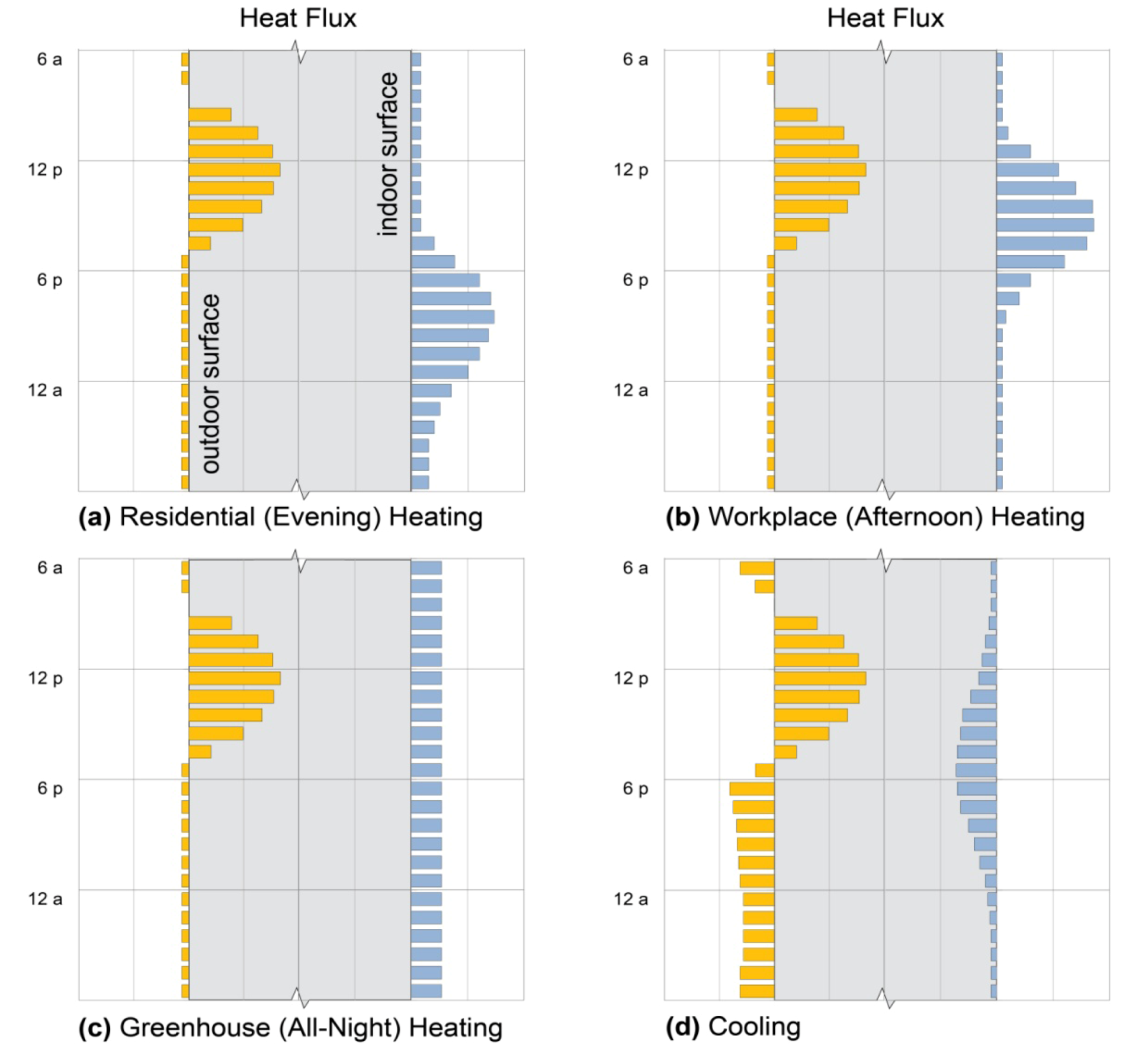
2.2. Ideal Heat Flux Profiles

For residential (evening) heating, the ideal massive element absorbs as much heat as possible from the sun or another heat source, such as a fire, during the day, and then releases the majority of its heat during the following 4–8 h. Heat released after midnight is less important, since people are well-insulated in bed [12]. In afternoon heating of workplaces, in contrast, mid-day heat gains are needed to offset afternoon (2:00–6:00 p.m.) heating needs: stored heat must be released much earlier and much more rapidly than in residential evening heating. In greenhouses, raising the lowest nighttime temperature is paramount, particularly to avoid freezing [29]. Since this is most likely to occur during early morning hours [37], the desired time-release profile is substantially longer and of lower amplitude in greenhouses. Daytime cooling, in turn, requires the dampening of peak daytime heat above all, ideally releasing that heat late at night in residential applications, or any time after occupancy in workplace applications [30] (Figure 1).

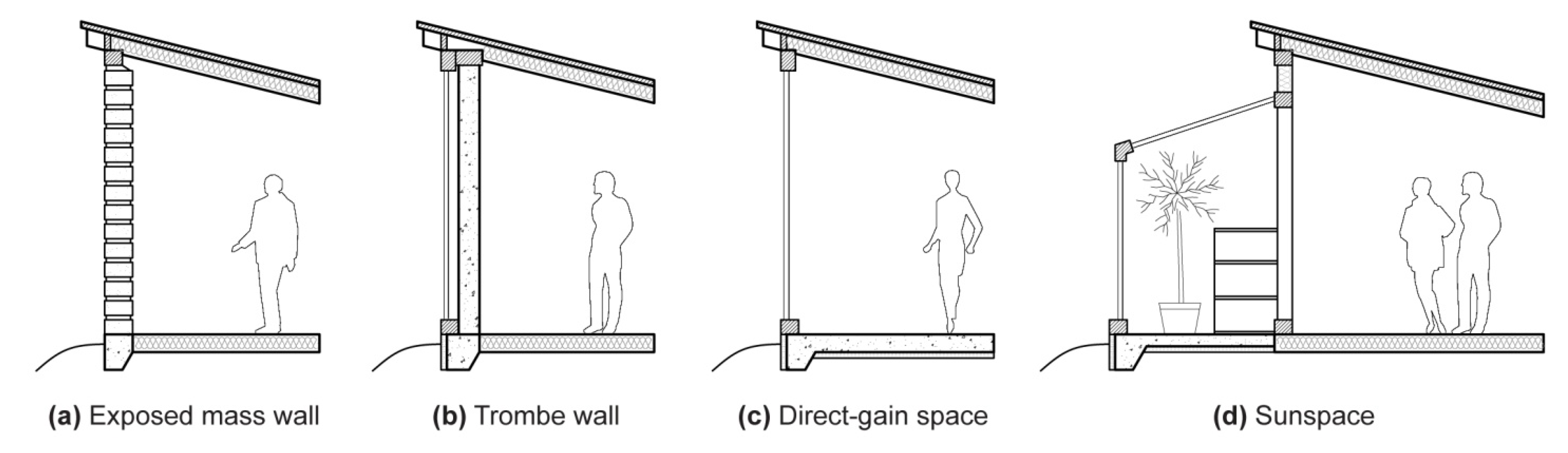
2.3. Design Approaches

Several recognizable design approaches have been developed that employ thermal storage mass, particularly for use in passive solar heating. Exposed exterior walls of adobe, stone, or cob were first used in ancient architecture, delaying the passage of heat from outside to inside during hot days while retaining some warmth throughout cool nights; these are still popular in desert climates (Figure 2a, [1,38]). These walls are typically structural, and adobe and rammed-earth walls are therefore often quite thick, greatly diminishing temperature swings in adjacent spaces. However, such walls often lose as much (or more) heat to the outdoors, at night, as they deliver to occupied space (e.g., Figure 4a), because outdoor temperatures are cooler [32,39,40].
The addition of a glass layer exterior to a mass wall substantially reduces its nighttime heat loss, creating an “indirect-gain” system known for its inventor, Felix Trombe ([41], Figure 2b). Trombe walls are found in numerous variations, potentially using concrete, stone, water, or even phase-change materials as thermal mass [42,43,44]. Indirect-gain systems characteristically intercept heat on one side and, several hours later, deliver part of it to the other side. These systems are also useful for cooling, however, shifting peak loads from hot afternoons, when electricity is expensive, to evenings or night times [45]; roof ponds and green roofs, for example, have indirect-gain configurations, but are primarily used for cooling [46].
Figure 1. Ideal heat flux profiles. Daily heat flux patterns across surfaces of thermal storage walls (gray sections), showing solar heat gain (yellow bars) and heat delivery to, or loss from, indoor space (blue bars), that would best meet design intents of (a) residential evening heating; (b) workplace daytime heating; (c) sunspace or greenhouse all-night heating; and (d) cooling. Flux magnitudes are arbitrary.
Geosciences 03 00063 g001
Figure 2. (a) Exposed mass thermal storage wall in the form of adobe bricks with batt-insulated floor and roof; (b) Trombe wall (unvented) with double-paned glass exterior to concrete; (c) Direct-gain space with double-paned glass and rigid foam-insulated concrete floor; (d) Sunspace with water-drum storage, insulated concrete floor, and double glazing.
Geosciences 03 00063 g002
“Direct-gain” systems, in contrast, admit sunlight and heat directly to occupied space through windows or skylights. Thermal mass is typically deployed in the floor or walls, where it absorbs and returns heat through the same surface (Figure 2c). Direct-gain systems store internal as well as solar gains, absorbing the energy of people, lights, or equipment in wall or floor materials for later return [11,12,13]. “Isolated-gain” systems, in turn, include sunspaces and greenhouses (Figure 2d). Like direct-gain systems, they admit solar heat to occupiable space through windows or skylights, but they are not usually intended to maintain thermal comfort for people. True isolated-gain systems mediate heat flow to living or work spaces through airflow or through massive walls, while greenhouses store heat for their own use, typically to maintain consistent warmth for plants [12,13,29].

2.4. Mass Sizing

For each of these configurations, architectural guidelines for sizing of thermal storage mass have been developed from combinations of experimentation and computer simulation. Virtually all of these assume the limited goal of reducing daily internal temperature swings, rather than providing heat when it is most useful, as noted above. Many guides further assume an optimal thickness (e.g., [13,15,16]), reducing thermal mass sizing to a matter of spatial area. As a result, numerous widely-used tables specify mass areas, or alternatively, “mass-to-glass” ratios, without considering specific heating (or cooling) design intents (e.g., [12,13,15,47]). While many guides acknowledge the importance of mass thickness to “thermal decrement”, or time delay between peak heat incidence and peak delivery [12,32], none take advantage of material thermal properties to control the kinetics of heat storage and release. As we will show, however, these properties have substantial influence on the heat flux patterns delivered, allowing thermal mass designs to respond quite directly to specific design intents.

3. Material Properties

The ability of a massive element to heat or cool occupied space depends both on the quantity of heat it can store and on the speed with which it exchanges heat with its surroundings. Heat capacity, thermal conductivity, emissivity, and the derived properties of thermal diffusivity and effusivity (also known as thermal inertia), as well as kinematic viscosity for liquid phases, together describe a material’s thermal behavior and allow a designer to predict thermal storage performance in a given environment.

3.1. Heat Capacity

Specific heat capacity c, or the increase in internal energy associated with a rise in temperature [units J/(kg K)], is an important measure of a material’s ability to store heat. Volumetric heat capacity, ρc [J/(m3 K)], is the product of density ρ and specific heat capacity c. Specific heat capacity varies widely among materials because, at the molecular level, substances have multiple ways of storing such energy: as translational and rotational motion of whole molecules, as vibrational motion of atoms within a molecule or crystal lattice, and as excitation of electrons to higher energy levels [48,49,50].
Gases, such as the air separating glass and mass in a Trombe wall, store energy primarily in translational and rotational motion; water and other liquids store greater energy in vibrational motion, and stone, brick, and other nonmetallic solids store energy primarily in vibrational motion [49]. These storage mechanisms contribute unequally to an object’s temperature, but a molecule’s internal energy must be equally distributed among them (at the temperatures of interest) [48]. As a result, temperature is not a direct measure of internal energy. However, it is temperature (rather than internal energy) that determines the tendency of an object to release energy to its surroundings (Section 3.2 and Section 3.3). For this reason, objects of higher heat capacity gain greater quantities of energy before increasing in temperature, and therefore before releasing stored heat to a given environment.
Materials that change phase (e.g., from solid to liquid) near temperatures of interest have an additional mechanism for thermal storage and release: these materials not only exhibit distinct specific heat capacities for each of their phases, but also store (or release) substantial latent heat during a phase change, without changing temperature. In effect, therefore, they exhibit extremely high heat capacities—high heat storage (or release) with minimal temperature change—across their phase-change temperatures, with striking consequences for heat delivery patterns (Section 5.3).
Tuning the heat capacity of thermal storage to the desired heat release profile, considering both magnitude and duration, is essential to the design of a high-performing system. The heat capacity does not address kinetic factors, however. Heat uptake rates, transmission from a surface to inner depths, and release rates are determined by the modes of heat transfer between mass and its surroundings: radiation, conduction, and convection [17,49,51].

3.2. Emissivity

Radiation transmits energy to thermal storage mass from the sun, a fire, equipment, lights, or people in a building. Radiation is also central to the delivery of heat from a massive storage element to cooler occupied space. Since every object emits, or radiates, energy in proportion to its absolute temperature, the rate of radiative heat transfer between two bodies depends only on their relative temperatures and on their abilities to radiate, or emissivities ε. The Stefan-Boltzmann law expresses this as:
Geosciences 03 00063 i001
where qr is the energy emitted per unit area and time [J/(m2 s), or W/m2], σ is the Stefan-Boltzmann constant [5.67 × 10⁻⁸ W/(m2 K4)], T is absolute temperature (K), and ε is the material’s emissivity [51]. For perfect emitters (“blackbodies”), ε = 1, while ε < 1 for “gray bodies”. The emissivities of typical mass storage materials are comparable and relatively high [52] (Table 1), but “low-emissivity” metallic coatings can diminish radiative transfers substantially. Applied as selective surfaces, these can minimize heat losses from either massive elements or, more commonly, from glazing (i.e., windows), to the outdoors (Section 5.1, below).

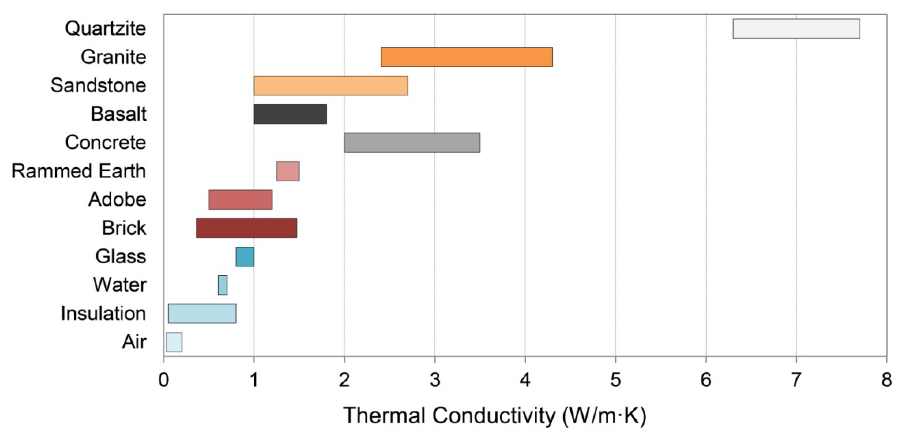
3.3. Thermal Conductivity

Once heat has been delivered radiatively to a mass surface, conduction determines how rapidly that heat will move through the mass, which in turn governs the delivery of heat to occupied space. Heat is conducted by the exchange of kinetic energy through collisions, mobile electrons, lattice vibrations, and other intermolecular interactions [53]. Thermal conductivity therefore generally increases with material density: gases have the lowest values, insulation values are similarly low, liquids are intermediate, and solids are high, with electrically-conductive solids highest (Table 1, Figure 3).
Table 1. Representative thermal storage material properties.
MaterialThermal Conductivity [W/(m·K)]Specific Heat Capacity [J/(kg·K)]Density (kg/m3)Thermal Diffusivity (mm2/s)Thermal Effusivity [J/(K·m2 s0.5)]Emissivity b
AirAir (20 °C) a0.0251,0051.2205
Insulation (foam) b0.031,210430.640
Insulation (fiber) b0.05960192.7430
WaterLiquid, 20 °C b0.64,1809980.141,580
GlassClear Float b0.98402,5000.431,3750.84–0.95
SaltsCaCl2·6H2O c1.01,4501,4900.461,470
Na2SO4·10H2O d0.541,9301,4850.191,240
Zn(NO3)2·6H2O e0.461,3401,9000.181,080
ClaysAdobe f0.5–1.2840–1,0001,200–2,0000.42–0.71900–1,2000.9
Rammed Earth g0.7–1.25870–12601540–18300.36–0.79970–1,7000.9
Brick b0.7–1.0790–8001,920–1,9700.4–0.61,000–1,2500.75–0.93
ConcreteHeavyweight b,h2.0–3.5900–1,0002,200–2,4000.89–1.62,000–2,8000.85–0.9
StoneBasalt i1.0–2.0720–10402,700–3,3100.52–0.711,680–1,9600.72
Sandstone i1.0–2.7730–9301,990–2,4500.54–1.511,340–2,2400.9
Granite i2.4–4.5650–8002,600–2,7201.15–2.552,060–3,0600.9
Quartzite i6.3–7.77002,500–2,7003.6–4.13,450–3,670
MetalsAluminum b2208962,7409023,0000.05–0.09
Copper b3933908,91011337,0000.07
Iron, cast b485007,2001313,0000.45
Notes: a [49]; b [52]; c [54,55]; d [55]; e [55,56]; f [7,39,57]; g [58,59,60,61]; h [62]; i [18,63,64,65,66].
Figure 3. Thermal conductivities. Typical thermal conductivity ranges of materials shown in Table 1 and used in thermal storage mass simulations; see Table 1 for sources.
Geosciences 03 00063 g003
The conductive heat flux q (W/m2) through a material is proportional to the temperature gradient across the material Geosciences 03 00063 i002 (K/m), according to Fourier’s law [51]:
Geosciences 03 00063 i003
where k is the thermal conductivity [W/(m K)]. A material with high thermal conductivity, such as a metal, transmits energy quickly when subjected to a relatively small temperature gradient. As a result, it carries heat rapidly from a warm outer surface toward a cooler inner core. This lowers the surface temperature, by an amount that depends on the heat capacity, and facilitates further radiative gains. Conversely, such a material releases energy to its surroundings rapidly when those surroundings cool.
An excellent thermal storage material therefore needs both a sizable heat capacity and appreciable thermal conductivity: a highly conductive material with a low heat capacity, such as most metals, cannot store much energy, while a material with a high heat capacity but low conductivity, such as a foam concrete, gains and releases heat too slowly to perform well in most applications.

3.4. Thermal Diffusivity

The thermal diffusivity,
Geosciences 03 00063 i004
measures how quickly a volume of material can equilibrate thermally with its surroundings: it increases with thermal conductivity k and decreases with the volumetric heat capacity ρc Accordingly, thermal diffusivity predicts the thermal penetration depth and temperature profile through a material’s thickness in a given environment [51].
A material of very high thermal diffusivity stores little energy, because it stays close to thermal equilibrium with its environment; a material of very low thermal diffusivity, in contrast, may or may not store much energy, but is slow to return any energy that is stored back to its environment. Matching this parameter to its design intent is therefore extremely important to achieving the desired performance.

3.5. Thermal Effusivity

To describe the quantity of energy exchanged across a mass surface, the thermal effusivity is used:
Geosciences 03 00063 i005
A material with a high thermal effusivity experiences a high heat flux across its surfaces during equilibration with surroundings of a different temperature. Thermal effusivity is also referred to as thermal inertia (e.g., [67]), because it gauges the magnitude of energy transfer required to change a material’s temperature, which is analogous to the influence of mechanical inertia on the magnitude of force required to change an object’s velocity. Adobe and foam insulation, for example, have identical thermal diffusivities (Table 1) and therefore show identical thermal profiles as they equilibrate with a given environment. However, heat flux is proportional to thermal effusivity, as confirmed by both theory [51] and experimentation [68]; as a result, heat flux across an adobe surface is over ten times greater during the equilibration process (Table 1). For effective heat delivery by thermal storage, therefore, obtaining the highest possible thermal effusivity, consistent with the needed diffusivity, is essential.

3.6. Kinematic Viscosity

Finally, the kinematic viscosity of a moving fluid, such as water or air, governs its rate of flow and the associated heat exchange with solid objects (i.e., “convection”). Exposed thermal storage mass is subject to forced convection in the form of wind, in which air flow is driven by pressure gradients. According to Newton’s law of cooling [51], heat exchange depends on the temperature difference between the wind and the wall, as well as a heat transfer coefficient that is controlled by the flow rate and surface roughness.
Natural convection, in contrast, describes fluid flow driven by buoyancy forces, such as those caused by the expansion of air or water with warmth. The vigor of any resulting fluid flow and heat transfer depend on competition between the speed with which fluid density gradients can drive flow, and the rate at which these density gradients are dissipated into the surrounding fluid. For example, in the case of a fluid-filled gap of width L that separates planar surfaces with temperature contrast ΔT, thermal convection depends on a dimensionless Rayleigh number defined by:
Geosciences 03 00063 i006
where g is the acceleration of gravity, β is the fluid’s coefficient of thermal expansion, v is its kinematic viscosity, and α is its thermal diffusivity. For cases where convection does take place, the Nusselt number Nu is defined as the ratio of the total heat transport to that which would take place by conduction alone if the fluid were stagnant. For water and PCM-Trombe wall systems (Section 5.2 and Section 5.3), physical and numerical experiments demonstrate that convective heat transport is important, so that Nu > 1 once Ra exceeds several thousand [69,70]. Convection in these systems is discussed further in the respective sections.
The above quantities vary in importance, depending on the quantity and timing of heat storage and delivery desired; the following examples, showing heat uptake and release in passive solar heating applications, illustrate variations in heating performance achievable by varying the factor or factors of greatest importance.

4. External Mass Walls

4.1. Adobe, Rammed Earth, and Brick

Earth is an ancient building material, still common in arid and semi-arid lands where other construction materials are scarce or expensive: an estimated 2 billion people currently live in earth homes, notably in Africa, India, China, Central and South America, and Australia [40,59,71,72]. Brick, or fired earth, is similarly widespread in building construction [73]; all three have thermal properties highly advantageous for thermal storage.

4.1.1. Adobe

Adobe, one of the earliest earthen building materials, consists of sun-dried mud bricks layered with clay mortar to form thick walls [38,40,74]. While adobe wall thickness is typically dictated by structural rather than thermal needs, the resulting 30–60 cm (12–24 in.) constructions greatly stabilize interior temperatures in both summer and winter [59,71,72,75].
Adobe derives its thermal properties from its primary substrate, clay, as modified by silt, sand, organic content, and moisture [39] (Table 1). Since adobe bricks tend to shrink and crack during drying, organic fibers (straw, rice husk, bagasse) are typically added for dimensional stability and tensile strength [38]. These diminish the heat capacity and thermal conductivity of adobe proportionately [40,57]. In contrast, moisture uptake tends to increase adobe’s thermal conductivity (and to erode the adobe itself); as a result, adobe walls are typically protected from moisture by stone foundations, stone parapets, lime plasters, or stuccos [74,76], or by mixing lime, cement, or bitumen (also known as asphalt) into the adobe itself [38]. The latter also increase the compressive strength of the bricks [39].

4.1.2. Rammed Earth

The compressive strength of earth can be increased greatly by compaction. To produce “rammed earth” or pise, layers of earth are built up within wooden or metal formwork, using a manual or pneumatic tamp to compress each layer. The earth mixture usually has greater sand and lower clay content than adobe and is typically stabilized with cement, resulting in a denser, more water-repellent product with greater thermal conductivity [39,72,77] (Table 1).
Adobe, rammed earth, and related earth materials such as cob and straw clay are gaining popularity in contemporary building for their beauty, local availability, low embodied energy, and high thermal inertia [38,39,71,78,79]. Thermally, the common perception that earth provides insulation [72,78] is refuted by experimental data [39,77], but the existence of this misperception highlights a valued property of external massive walls: the ability to dampen internal temperature swings [39,61]. This effect results not from insulation (i.e., low thermal conductivity), as the thermal conductivities of adobe and rammed earth are more than ten-fold greater than those of foam or fiber insulation materials (Table 1), but from the ability to store daytime heat for release during cooler nighttime hours. In coastal climates, additionally, moisture absorbed by earth walls at night is evaporated during the day, increasing the cooling effect [71].

4.1.3. Brick

The special durability of burned clay was well-known among ancient peoples, and fifty centuries after the first known adobe, Mesopotamians devised a controlled way to “fire” clay bricks in kilns, raising their temperatures above ~1000 °C for about a day and then cooling them slowly to waterproof them and increase their strength [73]. During firing, brickclay becomes a metamorphic rock: clay minerals release water, yielding a mixture of quartz and other minerals, particularly including mullite (3AlO3∙SiO2), which grows in thin strands and binds brick together like straw binds adobe. Iron also oxidizes to hematite, giving most bricks a reddish color [80,81].
Thermally, brick is quite similar to adobe and rammed earth, consistent with its basis in raw materials of sand and clay (Table 1). Bricks fired longer or at higher temperatures, however, become denser and more thermally conductive; high metal oxide content also increases thermal conductivity [82]. The practice of coring bricks to facilitate firing evenness, in contrast, lowers density and thermal conductivity, and large cores must be filled for passive solar applications [16]. While a great range of brick thermal properties is therefore achievable in theory, contemporary brick-making in developed countries is standardized, minimizing variation [16,82].
Just as adobe bricks are set in mud, bricks are set in mortar, and mortar can form up to 30% of the volume of a brick wall [82]. Early lime mortars were more porous than fired bricks, but contemporary Portland-cement mortars closely resemble bricks in specific heat capacity, thermal conductivity, and density, with the result that passive solar applications can reasonably assume uniform wall properties [16,73,82].

4.1.4. Performance: Exposed Earth Walls

In passive solar applications, adobe, rammed earth, and brick exterior walls (Section 2, Figure 2a) absorb solar energy through exterior surfaces and deliver part of that energy, many hours later, to the interior. This effect is illustrated in Figure 4a, showing adobe walls of 30, 45, and 60 cm thickness (12, 18, and 24 in. respectively) exposed to outdoor conditions of a typical sunny January day in Colorado chosen to illustrate patterns of thermal mass behavior clearly. (While these and all other patterns shown are characteristic of the respective materials and configurations, the quantities of heat stored and released are specific to the hourly solar radiation and temperature values of the day simulated (Section 7)). In this and all other simulations, indoor conditions were kept from falling below 68 °F (20 °C) by supplemental heat (Section 7).
Sun-driven heat fluxes into the three walls are similar, as are nighttime losses to the outdoors. Heat fluxes to the interior, however, vary dramatically with wall thickness: for the thinnest wall, peak heat delivery occurs at 10:00 p.m.; for the middle wall, 3:00 a.m., and for the thickest wall, no net heat at all is delivered to the interior under the conditions shown. The magnitude of heat delivery to occupied space varies greatly as well, with 10 W/m2 for the thinnest wall, 2 W/m2 for the middle wall, and −5 W/m2 for the thickest. At the same time, the thickest wall loses less total heat from the interior over the 24-hour period.

4.1.5. Designer’s Dilemma

The paradox above illustrates the designer’s dilemma in external mass wall sizing: should heat delivery during occupied hours be maximized (the thinnest wall), or should total heat loss from the interior be minimized (the thickest wall)? Standard evaluation methods of massive wall performance always favor the latter, because they assume constant indoor temperatures and they evaluate net gains and losses using monthly average indoor/outdoor temperature differences [7,13,15,31,32]. This approach is problematic for two reasons, however: first, it fails to account for thermostat setbacks during unoccupied hours, over-estimating the value of heat delivered passively during those hours. Second, it neglects warmer indoor temperatures created during some hours of heat delivery that diminish rates of that delivery, risking general over-estimation of delivered heat.
The approach presented here, in contrast, highlights daily patterns of heat uptake and release so that thermal storage designs can be matched to daily space-heating (or cooling) needs. While the current simulations omit thermostat setbacks for the sake of pattern clarity, their addition would simply improve performance of a design already well-matched to occupant needs. These simulations do, however, explicitly model internal warming during heat delivery, which limits the total extent of that delivery and which is not incorporated into conventional methods (Section 3 and Section 7).
The designer’s dilemma is therefore resolved by Figure 4a: for evening heating, the thinnest wall is best, and thermostats should be set back during the day to limit heat losses from the interior into the wall. For daytime heating, none of the three perform well, and alternative solutions should be investigated. For cooling, however, the thicker options are both worth investigating further through experimentation or simulations with summer weather data.
Figure 4. Exterior mass walls. Heat fluxes across outdoor (left axis) and indoor (right axis) surfaces of exterior walls of (a) adobe; (b) granite; and (c) concrete on a typical sunny January day in Denver, Colorado. Patterns show characteristic effects of thickness, thermal diffusivity, and thermal effusivity on timing and amplitude of heat delivery to the interior.
Geosciences 03 00063 g004

4.2. Stone

Stone was the predominant material used in large building construction prior to the 20th century [83]. Although its early use was structural, contemporary applications commonly use thin stone layers as a durable and attractive facing or veneer. ASTM International (formerly the American Society for Testing and Materials) publishes minimum standards for the strength properties, abrasion resistance, maximum water adsorption, and other key characteristics of marble, limestone, granite, sandstone and slate that designers should expect from quality building stone [83,84]. Developed to address structural considerations, these standards greatly limit the variety of stones that find common use in construction, but still leave room for considerable variation in thermal performance.
The enormous variety of mineral compositions, naturally mixed in myriad proportions and geometrical arrangements, give potential for a wide range of thermal properties in stone walls. Data compilations listing thermal conductivities, densities, and specific heat capacities of whole rocks and their constituents are numerous and extensive (e.g., [18,66]). Relative proportions and properties of major constituents in a building stone can be combined to estimate the overall thermal behavior, but in many cases, important trends in diffusivity and effusivity can be gauged simply by porosity, mineral packing arrangements, and quartz and feldspar content [18].

4.2.1. Mineral Content

With few exceptions, the mineral grains in building stones are small enough that many are traversed along the primary direction of heat flow, for example over the thickness of an external wall. Fourier’s law [Equation (2)] predicts that a significant temperature difference across the short distance of a grain diameter produces a large heat flux, and so tends to even out the temperatures of adjacent mineral grains. For this reason, adjacent grains approach a state of thermal equilibrium, with their temperatures evolving in sync as heat is transported over larger distances. This reasoning implies that the effective volumetric heat capacity ρc can be approximated by the average product of component densities ρi and specific heat capacities ci, weighted by their volumetric fractions ψi, so that [49,51]:
Geosciences 03 00063 i007
The specific heat capacities of minerals are inversely correlated with their densities [17,65], so typical volumetric heat capacities of building stones vary over a relatively modest range as long as the porosity is low. Mineral conductivities vary widely, with extremely high values in some rare cases (i.e., native metals, diamond), but a much more modest range exists for less exotic constituents. The relatively high thermal conductivity of quartz, combined with its common abundance, ensures that effective conductivities of many stones vary in proportion to quartz content. This leads for example to the relatively high conductivity listed for quartzite in Table 1. By contrast, the relatively low thermal conductivities of the feldspar minerals cause a general decrease in effective conductivity with feldspar content [18]. The presence of feldspars in granites lowers their conductivities relative to quartzite, whereas the higher quartz content in granite compared to basalt produces a higher thermal conductivity for the former stone (Table 1, Figure 3).

4.2.2. Mineral Packing

In addition to the mineral content, a stone’s effective thermal conductivity is also sensitive to the geometrical relationships among its constituents, as well as the predominant direction of heat flow [18]. In the isotropic arrangements typical of granite and basalt, the effective thermal conductivity can be approximated by the geometric mean so that,
Geosciences 03 00063 i008
when heat flow is parallel to layering, as in sandstone and slate, the arithmetic mean gives a better estimate,
Geosciences 03 00063 i009
whereas the harmonic mean describes the effective conductivity perpendicular to layering,
Geosciences 03 00063 i010
These considerations ensure that conduction across layering, as described by Equation (9), is always slower than conduction parallel to layering [Equation (8)] since the latter arrangement allows for preferential heat flow through more conductive pathways, whereas in the former arrangement an equal heat flux must traverse each layer. Less ordered arrangements of minerals that are best described by Equation (7) have effective conductivities that are intermediate between the two layered extremes.

4.2.3. Porosity

Air has much lower thermal conductivity and density than any solid constituent of stone (Table 1, Figure 3). Rocks that form deep below the Earth’s surface, like granite and quartzite, normally have very low porosities, so their constituent minerals control the thermal behavior. Volcanic rocks like basalt can form from bubble-rich magmas that leave behind many air-filled pores, but in most building stones these still occupy a relatively small fraction of the total volume (i.e., <10%). By contrast, rocks like sandstone that form by cementing clastic sediments together can contain many air-filled pores, and porosities of 20%–35% are not uncommon. At high values, porosity controls thermal performance.
Air causes an appreciable reduction to both the volumetric heat capacity and the thermal conductivity of stone, lowering the effusivity, and usually the diffusivity as well. However, stones with low porosities are typically preferred for building use because of the susceptibility of more porous materials to damage by the action of moisture and frost [83,84,85].

4.2.4. Performance: Exposed Stone Walls

Structural needs are more easily satisfied by stone, with its high compressive strength, than by adobe, allowing wall constructions to be thinner; here, granite illustrates thermal storage and release behavior of stone walls in 10, 20, and 30 cm (4, 8, and 12 in.) constructions (Figure 4b). Solar heat gains by the granite walls are much higher than those of the adobe walls, peaking at about 450 W/m2 on the day shown in accord with granite’s higher thermal effusivity (Table 1). The granite walls also deliver heat to occupied space much more rapidly, and in much greater quantity, than the adobe walls do: peak heat fluxes range from 40 W/m2 to 110 W/m2 and occur from 2:00 to 5:00 p.m., with heat delivery completed in the evening in all cases. Conversely, the granite walls lose much more heat from the interior overnight, in this illustration, than do adobe walls. This strikingly different heat delivery pattern illustrates granite’s much higher thermal diffusivity (Table 1).

4.3. Concrete

Quarrying, transporting, and dressing stone for construction can be expensive, and considerable excavation is often required for the substantial foundations needed to support the weight of stone buildings [83]. Usually concrete is much more economical than stone masonry, yet it possesses a comparable compressive strength and has much better tensile properties when properly reinforced. Moreover, the flexibility afforded by a building material that can be simply poured into a desired shape is sometimes an advantage over stone and earthen materials [62].
Much as in clastic sedimentary rocks, the pore volume of concrete controls the density and exerts a strong influence on thermal conductivity as well. The properties of the aggregate, which typically constitutes 70%–80% of the solid volume (the remainder is cement), are controlled by the mineral compositions that are employed [62]. For this reason, the thermal properties of concrete mimic those of building stones with similar mineral contents. Microstructures tend to be isotropic so that the effective thermal conductivity of a dense concrete can be approximated by the geometric mean of its constituent conductivities, as discussed for stone above and described by Equation (7). However, mixtures of fine and coarse aggregate with very different thermal properties and affinities are sometimes used and variations in cement composition can alter the effective thermal conductivity as well [86]. Many interesting applications for lightweight concretes are possible using nontraditional aggregates, including wood, rubber, and plastics, but for the purposes of illustration here, we specify thermal properties that characterize more standard concrete compositions (Table 1).

4.4. Performance: Exposed Concrete Walls

With respect to solar heat gain, concrete walls show similar diurnal patterns to those of adobe and granite walls, above (Figure 4c). The heat fluxes across external concrete surfaces are only slight lower than those for the granite, consistent with concrete’s comparable thermal effusivity (Table 1). At the internal faces, however, the magnitude of heat delivery is intermediate between those of adobe and granite, with peak values of 10–80 W/m2. Hours of peak delivery are also intermediate between those of adobe and granite, occurring between 4 p.m. and 9 p.m., and the peak amplitude delivered is attenuated accordingly. This intermediate heat delivery pattern illustrates concrete’s intermediate thermal diffusivity (Table 1): heat travels more rapidly through concrete than through adobe, but less rapidly than it does through granite. Note that emissivity values are comparable among the three materials (Table 1), such that radiative heat transfers should be similar at any given temperature [Equation (1)].

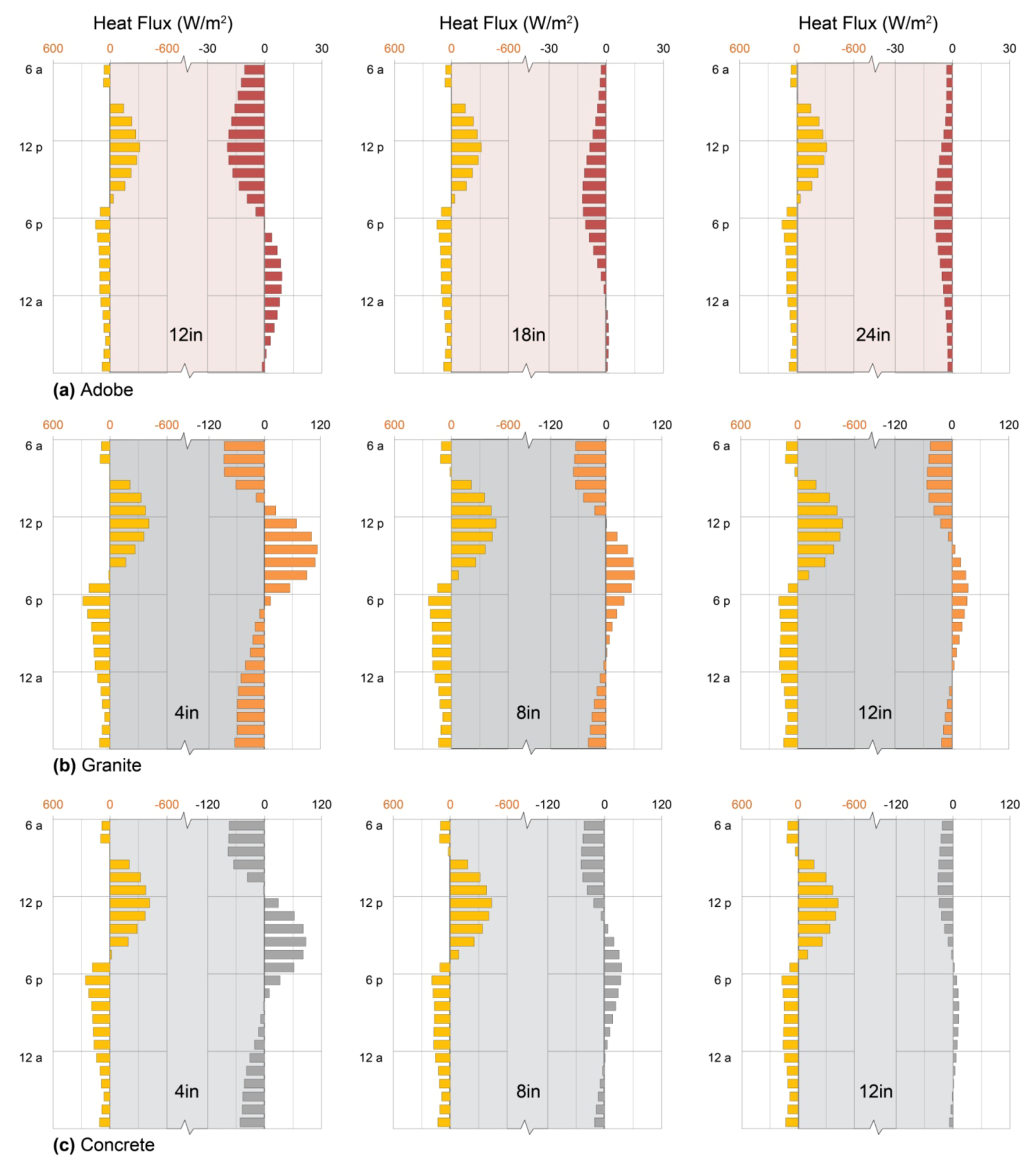
4.5. Performance: Materials for Exposed Mass Walls

The comparison of adobe, granite, and concrete illustrates well the consequences of a material’s thermal properties to heat storage and delivery: greater thermal effusivity in a material allows it to gain and release greater quantities of heat, while greater thermal diffusivity allows it to transfer heat from one side to another more rapidly. Together, these determine patterns of heat storage and delivery that may easily be matched to patterns of heating (or cooling) need.
Notably, each wall experienced a net heat loss from interior to exterior in Figure 4, consistent with the primary application of exposed earth, stone, and concrete walls in cooling or mild-climate heating applications [2,38,40,57]. Heat losses from thermal storage mass can be diminished substantially, however, by further material thermal engineering.

5. Trombe Walls, Water Walls, and PCM Walls

5.1. Trombe Walls

The “Trombe” wall adds an exterior layer of glass to a mass wall (Figure 2b), vastly improving heat storage of an otherwise exposed wall by diminishing convective and radiative losses to the outdoors [7,87,88]. Designed in 1966 by French engineers Trombe and Michel [41], original walls used single clear glass spaced 2–5 cm from the mass surface; later, double and low-emissivity glazing achieved further improvements in heat retention, though at some expense to solar heat gain [26,44,89]. Trombe walls were originally designed for heating, but work in hot climates has adapted them for cooling-load dampening and shifting as well [16,45].
Addition of vents near the floor and ceiling of a Trombe wall allows natural convection to circulate air around the mass, drawing heat from both faces [26], and vented Trombe wall design optimizing convection in the air space between glass and mass has recently been reviewed [89]. Here, however, we consider only unvented Trombe walls to emphasize the roles of glazing and selective surfaces.

5.1.1. Selective Surfaces

In the 1980s, black-coated aluminum and copper foils were investigated as “selective surfaces” or “selective coatings” that, when applied to the sun-facing mass surface, improved heat storage even more dramatically [26,87,90], although they fell short of creating the “one-way heat valves” enthusiastically described by some designers [87]. High thermal conductivity of these coatings allowed them to admit solar gain readily, while low emissivity (Table 1) allowed them to diminish radiative heat loss to the outdoors (Section 3.2).

5.1.2. Sizing

Trombe walls are typically described as having optimal thicknesses, in the range of 25–35 cm (8–14 in.), that minimize indoor-air temperature swings and maximize annual heating benefit [7,15,16,32]. Trombe walls are also described as having long “lag times”, usually in the realm of 8–12 h, referring to the time between peak solar gain and peak heat delivery to the interior, but frequently interpreted as the time until any substantial heat is delivered [12,13,16,32]. Third, a Trombe wall’s performance is typically evaluated according to its “solar savings fraction” (SSF), or proportion of total energy that it saves in a building, evaluated in terms of aggregate monthly heating need [12,15,26,91].
These three parameters—thickness, lag time, and SSF—currently govern Trombe wall design and deployment, but work remains to advance design sensitivity to the needs of a particular space. Heat (or cooling) is most useful at certain hours: during the day for an office, school, or shop; during the early morning or evening for a residence; all night for a greenhouse (Figure 1). Timing the heat delivery (or absorption) of a passive system is therefore at least as important as maximizing it, if not more so.

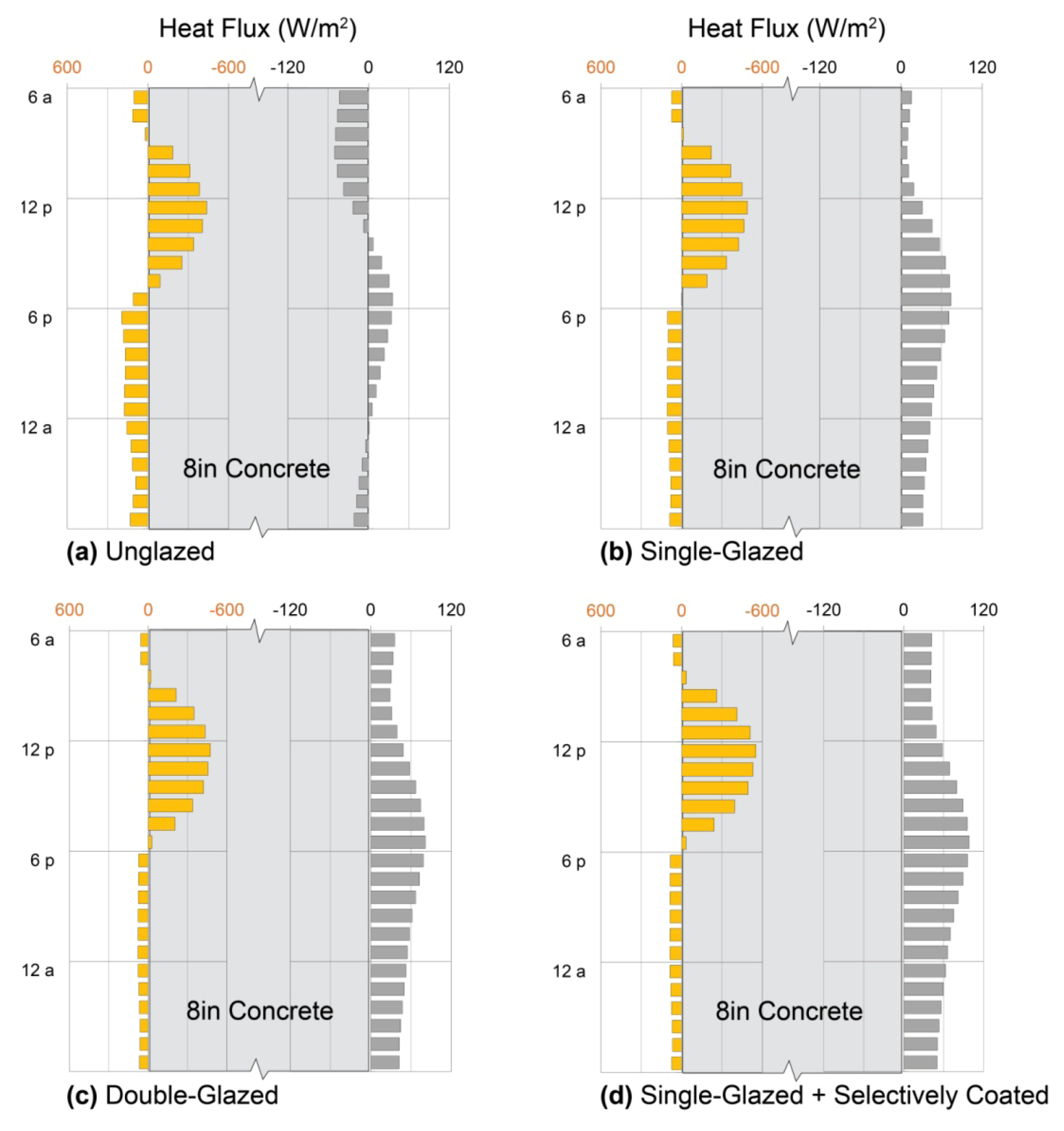
5.1.3. Performance: Concrete Trombe Wall

To illustrate the thermal behavior of an unvented Trombe wall in passive solar heating, the exposed mass walls of the previous models (Section 4, Figure 4) were replaced with Trombe walls using concrete mass (Table 1) with varying external layers. For comparability, simulations employed the same building under the same conditions; in addition, Trombe Wall algorithms were called upon to simulate natural convection in the airspace between glass and mass [87,88] (Section 7).
The effectiveness of even a single pane of clear glass is evident in Figure 5a,b: for the illustrative day, nighttime heat loss is approximately half of that lost by the unglazed wall, while heat gain to the interior is positive for every hour. Heat gain during collection is even improved slightly. The basis for this improvement lies partly in the protection of the wall from forced convection (e.g., wind; Section 3.6) and partly in the opacity of glass to the long-wave radiation emitted by the warm mass wall [92]. The air between the two has insulating properties, as well (Table 1): with low effusivity, motionless air transfers little heat as it equilibrates with a warmer or cooler environment, although natural convection can increase its effective effusivity substantially (Section 3.6). In the single-glazed Trombe wall shown (Figure 5b), therefore, benefitting from its layers of glass and air, heat delivery to interior space rises noticeably only a few hours after heat collection begins. Heat delivery peaks by 5:00 p.m., afterward declining gradually such that midnight heat delivery is still over half of peak delivery. In contrast, heat delivery by the unglazed wall reaches zero by midnight.
Double clear glazing, on the sunny cold day shown, further reduces Trombe wall heat loss and increases delivery to occupied space, maintaining the same hourly pattern observed with single glazing; in this case, solar heat gain is not noticeably diminished (Figure 5c). Addition of a selective coating representing black oxide-coated copper, however, has an even stronger effect than addition of a second glass layer (Figure 5d), increasing both heat gain and heat delivery in the characteristic pattern.
Trombe walls are often touted for “long thermal lag times” and “slow, even nighttime” heat delivery [12,13,16,32]. In contrast, however, the characteristic patterns of Figure 5 show that Trombe walls made of concrete, the most common material, transmit solar heat gains to the interior fairly rapidly; concrete’s fairly high thermal diffusivity (Table 1) is responsible. Although a peak in heat delivery may be delayed until evening, appreciable heat is delivered for many hours before that. This pattern illustrates the problem that occurred in the Zion Visitors Center in Utah: an 8–10 h thermal lag was assumed for an 8-inch thick grouted CMU wall, with properties similar to concrete [93], but investigation of the completed building soon revealed that the wall was delivering heat hours earlier than expected, with unintended consequences [94]. Nevertheless, effective workplace heating by Trombe walls appears quite promising, given their characteristic heating patterns, as long as the hourly behaviors of the walls are considered.
Figure 5. Trombe walls. Heat fluxes across outdoor (left) and indoor (right) surfaces of 20 cm (8 in.) concrete walls with exterior surfaces of (a) no glazing; (b) single clear glazing over a 15 cm (6 in.) air cavity; (c) double clear glazing over a 15 cm (6 in.) air cavity; and (d) single clear glazing over a 6 in. air cavity and a selective coating of black-coated copper foil adhered to the concrete. Each model was simulated on the same typical sunny January day in Denver, Colorado; patterns show characteristic effects of glass and air on the timing and intensity of heat delivery to interior spaces.
Geosciences 03 00063 g005

5.2. Water Walls

Substituting the concrete or adobe of a mass wall with water, a substance of higher specific heat capacity with potential for natural convection (Section 3; Table 1), offers compact storage and rapid heat delivery to spaces [15,16] with potential to match daytime heating needs. Indeed, the natural (heat-driven) convection of water in a solar wall can be so great that some models treat the water as having infinite thermal conductivity, so that its temperature remains spatially uniform [7,32].

5.2.1. Containment and Sizing

To contain water for thermal storage, designers have experimented with rigid tubes, plastic bags within rigid tubes, stackable glass chambers, corrugated metal culverts, steel tanks, and 55-gallon drums [12,16,32,95]. Plastic containers may be left translucent, allowing visible light to enter [11,95], but most are painted black or coated with selective surfaces [12,16]. Water chambers are usually placed behind external glazing, such that they resemble Trombe walls [16,32] or fully internal mass (Section 6.2).
Like other massive storage walls, water walls are typically evaluated by a monthly heating contribution, estimated from monthly average indoor-outdoor temperature differences, rather than by daily matching of heat delivery to occupant needs [12,15,26,91]. In contrast to solid Trombe walls, however, for which design guides prescribe specific thicknesses beyond which performance declines (Section 5.1), water walls are viewed as offering ever-increasing heat delivery with volume, diminishing returns notwithstanding [15,26], and to have no maximum thickness beyond which performance declines [7,26,32]. The basis for this perception is understandable, but heat delivery patterns of water walls are, in fact, highly tunable by varying their thicknesses. Illustration of this through further simulations (Section 5.2.3), however, required external calculations of convective heat transfer for incorporation into EnergyPlus models (Section 7).

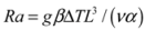
5.2.2. Convective Heat Transfer

To model convective heat transfer, we make use of published correlations between the Nusselt number Nu and the characteristic Rayleigh number Ra (Section 3.6). Of particular interest for the water wall (and the PCM-Trombe wall discussed below) is the effective thermal conductivity across a fluid-filled horizontal gap. At high Ra, Nu is approximately proportional to Ra1/3 and does not depend strongly on the aspect ratio between the gap height and its width (e.g., [69,70]). In principle, Nu should also be affected by the ratio of kinematic viscosity to thermal diffusivity, Pr = v / α. However, correlations for the controls on Nu along a single vertical plate suggest that the heat transfer is relatively insensitive to Pr, especially as it attains higher values for more viscous fluids [96]. Accordingly, we adopt the heat transfer correlation proposed by Wright [69] for the typical operating range with Ra > 5 × 10⁴ and take
Geosciences 03 00063 i011
So that the heat transport is described by Fourier’s law, Equation (2), with k replaced by an effective thermal conductivity of ke= Nu·k. This predicts a linear relationship between ke and gap width L, for example reaching 9.7 W/(m K) (Nu = 16) when L = 10 cm (~4 in.) and the temperature contrast across the wall is ΔT ≈ 1 °C.
From Equation (5) Ra is proportional to ΔT, so Equation (10) implies that Nu and the effective thermal conductivity ke are even higher when the temperature contrast is larger because convection becomes more vigorous and so tends to diminish temperature contrasts more rapidly. By the same reasoning, smaller temperature contrasts are characterized by lower ke. However, since the Nusselt number correlation described by Equation (10) implies that ke is proportional to the 1/3 power of ΔT, changes in ke are proportionally much more modest than changes in ΔT. Accordingly, for each wall thickness we adopt a single value of ke that corresponds to the expected value of Nu for a nominal temperature contrast of ΔT ≈ 1 °C. This simplification should not influence the overall patterns of performance that are the focus of this work.

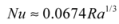
5.2.3. Performance: Water Wall

To illustrate a water wall’s performance in passive solar applications, the massive storage walls of the previous models were replaced with water walls in both exterior wall and Trombe wall configurations; in the exterior wall configuration, only a single layer of clear glass separated the water from the outdoors (Figure 6a).
Three main results follow from water’s natural convection: first, outside surfaces remain cooler during the day, allowing water walls to gain more heat than solid walls of equivalent total capacity [Equation (1)]. Second, water walls begin delivering heat only a few hours after heat gain begins, and third, outside surfaces stay warmer at night, making water walls more vulnerable to nighttime heat losses (remove paragraph break here). These trends are prominent in the exterior water walls (Figure 6a), which achieve the greatest passive solar heat capture of the materials examined to this point (see adobe, granite, and concrete in Figure 4). The exterior water walls lose more heat at night, however, due to the same high effective thermal conductivity that enabled such extensive solar gain. As a result, the net heat delivery of an exterior water wall is not substantially different from that of an exterior concrete wall of equivalent thickness, under the conditions shown. Note, however, that concrete’s thermal lag increases substantially as thickness increases (Figure 4c), while a water wall’s thermal lag does not (Figure 6a), due to increases in natural convection (and effective thermal conductivity) with wall thickness (Section 5.2.2).
In a Trombe wall configuration, water’s convective heat transport combined with the heat retention capabilities of the confined air space yield dramatic results (Figure 6b): in the thinnest wall, appreciable heat flux begins just hours after insolation and continues in a sustained broad peak through the afternoon, without net heat loss at any hour. The intensity and duration of this delivery can then be modulated by wall thickness: doubling the thickness to 20 cm (8 in.) substantially increases nighttime delivery at the expense of peak afternoon delivery, while increasing the thickness further to 30 cm (12 in.) results in virtually constant 24 h delivery (Figure 6b). Comparison of 8in water and concrete Trombe walls, in turn, highlights water’s higher effective thermal effusivity and diffusivity in increasing solar heat collection and extending heat delivery into early morning hours (Figure 5c and Figure 6b). Convection causes the effusivity to increase above water’s inherent effusivity listed in Table 1 by a factor of Geosciences 03 00063 i012, while the effective diffusivity increases by a factor of Nu. As a result, convective heat transport may be used to further advantage in conditioning entire spaces through cold nights, as illustrated below (Section 6).
Figure 6. Water Walls. Heat fluxes across outdoor (left) and indoor (right) surfaces of (a) exterior water walls and (b) double-glazed Trombe water walls of thicknesses 10 cm (4 in.), 20 cm (8 in.), and 30 cm (12 in.), respectively on a typical sunny January day in Denver, Colorado. Note the scale expansion necessary for exterior water wall heat uptake. Water tanks are each bounded by 6 mm black-coated (but not selectively-coated) glass. In exterior walls, patterns show the marked effects of water’s convection on its effective thermal conductivity, which is otherwise comparable to that of adobe at 0.6 W/(m K). Trombe water walls, in contrast, show patterns that result when external glazing limits heat loss to the outdoors.
Geosciences 03 00063 g006

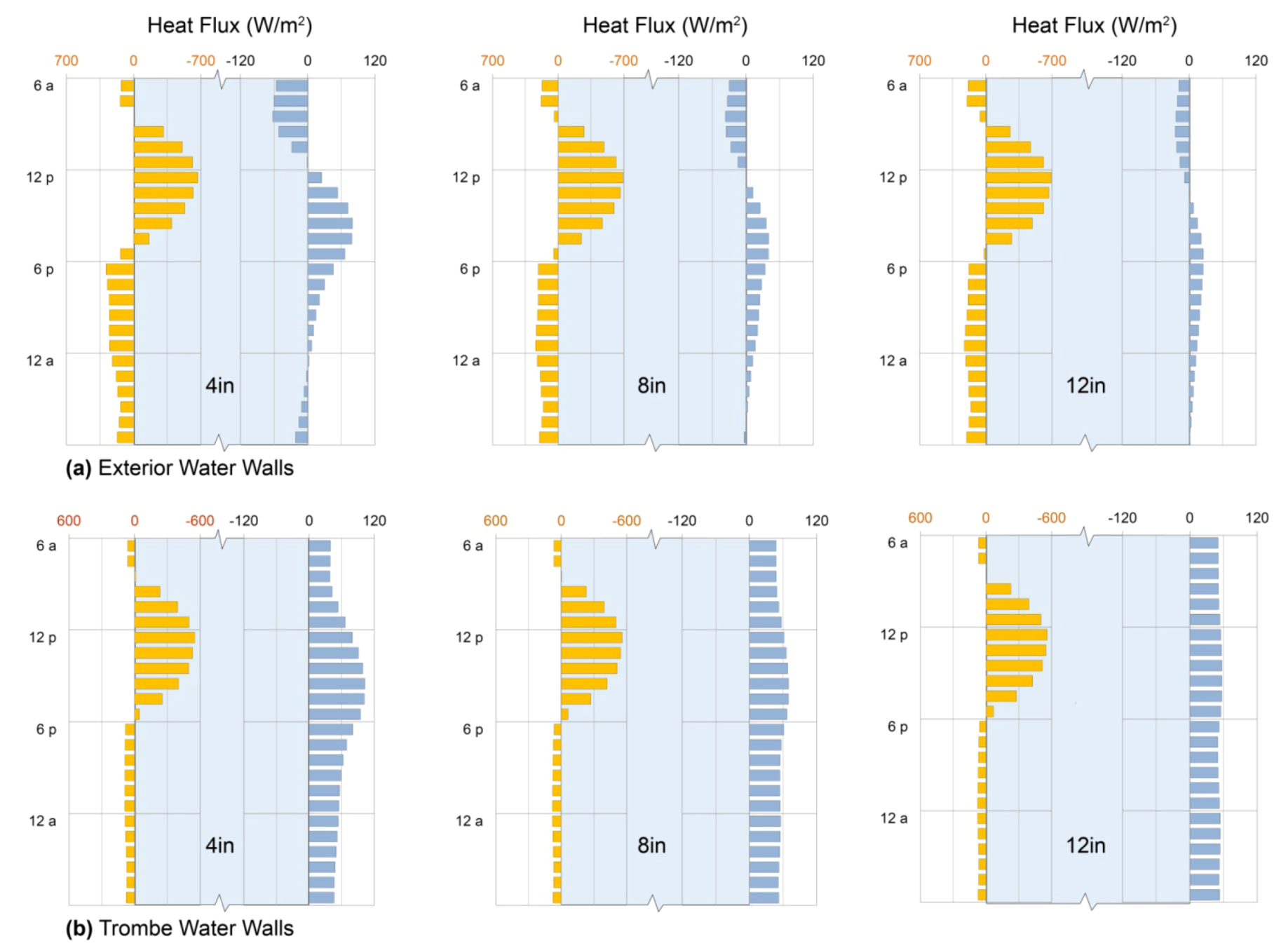
5.3. Phase-Change Material Walls

The warmer a surface becomes, the more slowly it accepts further heat from the sun, a fire, or other warm body, and the more rapidly it loses its heat to cooler objects [Equation (1)]. While natural convection within a water wall cools the heated surface (Section 5.2), even water gains heat less rapidly as its temperature rises. When a material stores heat by melting or evaporating, however (Figure 7a), the temperature remains nearly constant across the phase change, and the “latent” heat stored is invulnerable to increased radiative loss. As a result, phase-change materials (PCMs) can store and release solar (or other thermal) energy with great efficiency by melting during the day and transferring that energy to interior spaces, at nearly constant rates, by re-freezing overnight [19].
Figure 7. Phase-Change Materials. (a) Enthalpy changes as a function of temperature for antarcticite (CaCl2·6H2O), mirabilite (Na2SO4·10H2O) at 33% and 44%, and zinc sulfate hexahydrate [Zn(NO3)2·6H2O], showing phase-change temperatures and enthalpies of fusion under congruent melting; (b) Phase diagram of mirabilite, adapted from [55].
Geosciences 03 00063 g007

5.3.1. Candidate Materials

PCMs most suitable for indirect-gain systems possess phase-change temperatures in the range of 20–40 °C (68–104 °F): they must freeze above the desired indoor temperature, so that heat released by freezing is useful. However, they must not require overly high temperatures to melt, because the phase change might then occur only rarely. Ideal PCMs also have high latent heats of fusion, ease of prolonged containment, low susceptibility to supercooling, low toxicity, and low cost. While numerous organic phase-change materials melt and freeze in the desired temperature range, they are somewhat expensive and they tend to possess relatively low latent heats [19,20,21]. Salt hydrates are generally affordable, in contrast, but problems of supercooling, thermal expansion, formation of sharp crystals, and incongruent melting can compromise their performances. Nevertheless, a number of salt hydrates exhibit advantageous melting transitions and are fairly tractable in building applications: CaCl2∙6H2O, or antarcticite; Na2SO4∙10H2O, or mirabilite; and Zn(NO3)2∙6H2O [19,20,21,97].

5.3.2. Deployment Strategies

Phase-change materials are particularly attractive in building applications for their compact thermal storage [13]. Because substantial heat capacity can be realized in less than an inch (2.5 cm) of thickness, applications can take exceptionally thin forms, such as PCM-packed ceiling tiles [12] and PCM-impregnated gypsum board [19]. In addition, PCMs are promising as low-volume replacements for water in Trombe-style walls (Section 5.2), encapsulated in thin tubes or pouches, and in internal storage tanks (Section 6) [56,98,99,100].
Phase changes are accompanied by changes in density and therefore in volume. While the large volume changes associated with sublimation and boiling are prohibitive for building thermal storage applications, several strategies have been developed to accommodate the modest (i.e., 10%) volumetric expansion that occurs upon melting. Rigid tanks may simply be oversized; long, thin tubes may be assembled into arrays, and deformable plastic pouches may be used [21,97,100]. Although sharp dendrites can cause punctures in such pouches [101], these crystal forms develop under a restricted range of conditions, most commonly when the liquid is supercooled before freezing. Nucleating agents can be added to avoid supercooling [97], although these may cause other problems, including the formation of meta-stable phases in some systems [102]. Micro-encapsulation techniques enable PCMs to be incorporated within concrete, wallboard, and plaster, potentially offering another solution to volume expansions, but these have found limited applicability to salt hydrates [19].

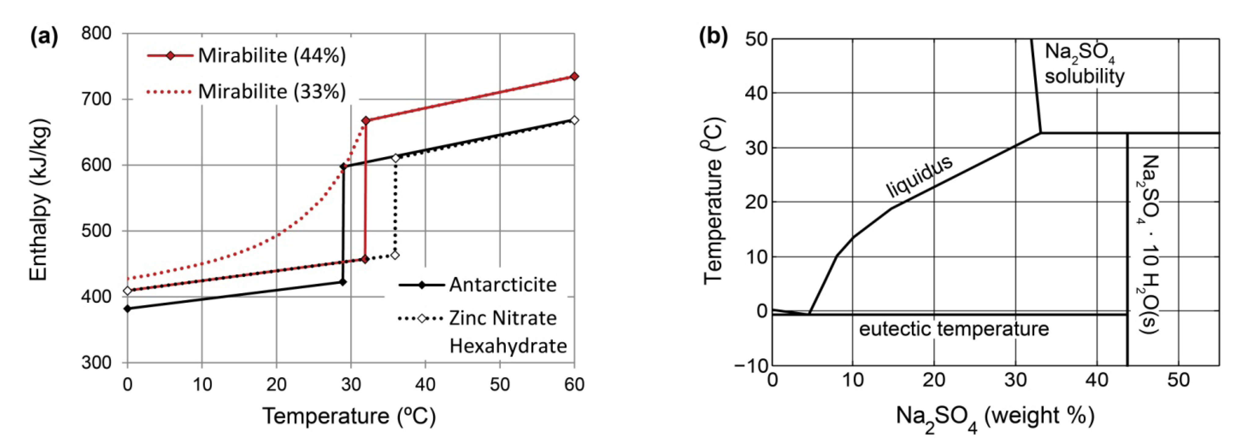
5.3.3. Phase-Change Enthalpies

As melting or freezing takes place, the difference between the solid and liquid densities leads to small changes in specific volume. As a result, a portion of any heat transfer involves pressure-volume work and is therefore not available to change the system’s internal energy. The “specific enthalpy” is therefore useful for comparing energy storage among different PCMs because a change in enthalpy accounts for both the change in internal energy and the work associated with volume changes at constant pressure. On either side of the melting temperature, a PCM’s enthalpy is directly proportional to temperature through the specific heat capacity c, as illustrated by the sloping solid lines for three salt hydrates in Figure 7a. At the phase change temperature, however, the enthalpy of the solid is higher than the enthalpy of the liquid, with the difference given by the latent heat of fusion L. This is the energy that can be stored during melting or released during freezing, and it gives rise to an abrupt step in specific enthalpy at the melting temperature. For each of the aqueous solutions and solid hydrates shown in Figure 7a, the size of the jump in enthalpy provides a quantitative measure of the amount of energy that is stored when the solid hydrate melts completely.
The fourth curve in Figure 7a shows the enthalpy changes for a 33% by weight aqueous solution of sodium sulfate, which does not have an abrupt phase change, but instead shows a more gradual change in enthalpy at temperatures below 32 °C (90 °F) [54,55,56,102] (remove paragraph break here). Just as the solidification and melting of igneous rocks and sea ice occur over a range of temperatures as the residual liquid composition varies (e.g., [103,104]), salt hydrates can form mushy solid-liquid mixtures that broaden the phase transition so that it is no longer isothermal, and the step-change in enthalpy disappears (Figure 7a, Section 5.3.4).
Such behavior can be avoided if the salt solubility is high enough to match the composition of the solid hydrate. This is the case for calcium chloride hexahydrate, also known as the mineral antarcticite, which melts at 29 °C (84 °F) to form an aqueous solution with a calcium chloride concentration of 50% by weight [54,105]. Likewise, a super-eutectic aqueous solution can be formed, with 64% zinc nitrate by weight, that freezes at 36 °C (97 °F) to form solid zinc nitrate hexahydrate [55,56,106]. In their fluid states, both of these PCMs are able to convect, which helps them to maintain a near-uniform temperature throughout.

5.3.4. Solubility Mismatch

The solubility of sodium sulfate in water reaches a maximum of approximately 33% by weight near the melting temperature of its decahydrate form, the mineral mirabilite, which is 44% sodium sulfate by weight (see Figure 7b) [55]. Heating pure crystalline mirabilite to its melting temperature of 32 °C (90 °F) produces an aqueous solution, but the solubility of sodium sulfate (33% by weight) is lower than the 44% sodium sulfate content of mirabilite, and the remaining 16% precipitates as Na2SO4(s): pure sodium sulfate. In consequence, the effective latent heat of the two-phase mixture is diminished to 84% of its tabulated value [55]. The solid line in Figure 7a for a solution of 44% sodium sulfate corresponds to a case where the sodium sulfate crystals remain in close proximity with their saturated solution so that the entire assemblage can recombine to form solid mirabilite upon cooling to 32 °C (90 °F).
If the sodium sulfate crystals that precipitate when mirabilite melts are able to settle, a process that can be limited by addition of thickening agents, the remaining aqueous solution is too dilute to refreeze completely upon subsequent cooling [55]. Instead, when freezing commences near 32 °C (90 °F), the concentration in the remaining liquid is depleted, which causes its phase change temperature to decrease gradually along the liquidus curve (see Figure 7b). Just beyond the onset of crystallization, the liquid concentration drops by approximately 0.8% for every 1 °C decrease in temperature. Further cooling produces more and more solid mirabilite as the residual liquid is diluted progressively; this gradual freezing can continue until an ice/mirabilite solid solution forms at the eutectic temperature of approximately −1 °C (30 °F). Figure 7a shows how the enthalpy of a 33% aqueous sodium sulfate solution evolves as the temperature is decreased below 32 °C(90 °F) and mirabilite gradually accumulates.

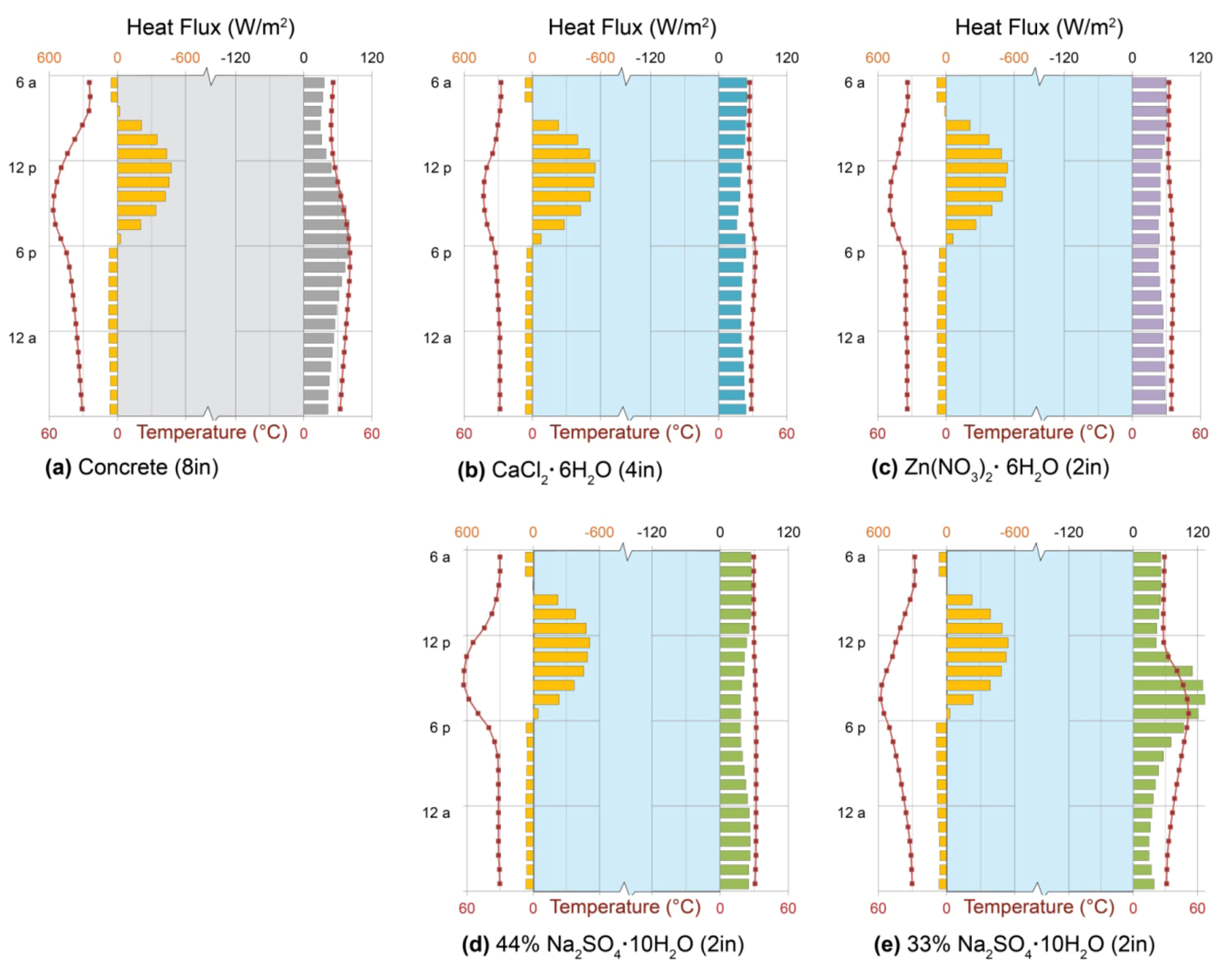
5.3.5. Performance: PCM-Trombe Wall

The striking features of PCM performance, in comparison with single-phase materials, are the extent of heat gain and steadiness of heat delivery that can be achieved. When the 10 cm (8 in.) concrete of the previously-described passive solar Trombe wall is replaced by a salt hydrate PCM, comparable heat gain can be achieved in a much thinner wall: calcium chloride hexahydrate, or antarcticite, accomplishes the same heat gain in half the thickness (4 in.; 10 cm), while zinc nitrate hexahydrate and 44% sodium sulfate decahydrate, or mirabilite, need only one-quarter (2 in.; 5 cm) (Figure 8a–d).
External wall temperatures show that each of the three high-performing salt hydrates (Figure 8b–d) melted fully during the day, climbing above its respective phase-change temperature and gaining heat sensibly, but remained warm enough to avoid fully freezing (and entering sensible cooling) at night. As a result, overnight heat delivery is virtually constant by each of the three PCMs under the conditions shown, with each phase change temperature controlling the external and internal wall temperatures and, therefore, rates of heat delivery to the interior. Antarcticite’s phase change temperature of 29 °C (Figure 7a) is the lowest; as a result, its wall maintains the lowest temperatures and delivers slightly less heat to the interior than the others (Figure 8b). Mirabilite, with a phase-change temperature of 32 °C, maintains warmer temperatures and delivers slightly more heat (Figure 8d), while zinc nitrate melts at 36 °C, maintains that temperature at the inner wall surface, and delivers the most heat accordingly (Figure 8c).
The thermal behavior shown for mirabilite (Figure 8d) represents ideal behavior of the pure substance, as discussed above, in which no solid Na2SO4 precipitates from the system during repeated cycles of freezing and thawing. Figure 8e, in contrast, illustrates the consequence of such precipitation and loss, which effectively reduces the concentration of the mixture to 33% Na2SO4∙10H2O by weight. In this case, as the system cools, it separates into an aqueous solution of Na2SO4, with concentration given by the curved liquidus line of Figure 7b and a solid phase of Na2SO4∙10H2O. While the system can fully melt, it can no longer fully freeze at the temperatures of interest, diminishing its effective latent heat, and its phase change takes place over a much greater temperature range (Figure 7a). As a result, wall surface temperatures are no longer kept near the nominal phase-change temperature, and heat delivery no longer exhibits the characteristic PCM constancy (Figure 8e).
Thin PCM walls designed to freeze and thaw fully under the conditions of interestas well as thick water walls (Figure 6b), therefore exhibit heat uptake and delivery patterns well-suited to steady, all-night heating of greenhouses, sunspaces, barns, sleeping quarters, and other spaces in which early-morning heat or constant temperatures are of paramount importance.
Figure 8. Phase-change material (PCM) Trombe walls. Heat fluxes (bars) and surface temperatures (symbols) across outdoor (left) and indoor (right) surfaces of double-glazed Trombe walls using, for thermal storage: (a) 20 cm (8 in.) concrete; (b) 10 cm (4 in.) antarcticite, CaCl2·6H2O; (c) 5 cm (2 in.) Zn(NO3)2·6H2O; (d) 5 cm (2 in.) 44% mirabilite, Na2SO4·10H2O; and (e) 5 cm (2 in.) 33% mirabilite, Na2SO4·10H2O. Each salt hydrate is enclosed in 6 mm black-coated, but not selectively-coated, glass. Patterns show the even heat delivery characteristic of phase-change materials, modified by the latent heat of fusion and phase-change temperature of each material, on a typical sunny January day in Denver.
Geosciences 03 00063 g008

6. Internal Mass: Direct-Gain and Sun Spaces

Previously-discussed thermal storage systems each involve walls, in which heat is collected on an exterior surface and must pass completely through the wall for delivery to occupied space. Floors, however, are also conventional locations for thermal mass, as are interior storage tanks. In these configurations, heat is admitted through windows or skylights, collected by interior surfaces, and delivered some time later to interior space by the same interior surface [11].

6.1. Direct-Gain Systems

Direct-gain systems collect heat entirely within occupied space (Figure 2c), where “occupied space” is expected to remain within the limits of human comfort [7,13,15,34,107]. In contrast, an analogous Trombe wall cavity may easily reach temperatures of 55–80 °C (150–180 °F) during collection [16]. The combination of glass and thermal mass in a direct-gain system, therefore, is called on to perform two sometimes conflicting functions: to collect enough energy to deliver substantial heat later, when it is needed, but also to maintain comfortable temperatures within the occupied space during collection.

6.1.1. Comfort

The priority of thermal stability during solar collection is unique to direct-gain systems and persists even in design of spaces that are not occupied during all hours [7,12,13,14,15,34,107]. Residential direct-gain systems, for example, might easily tolerate high mid-day temperatures, when occupants are away, as well as low early-morning temperatures, when occupants are asleep. Nevertheless, the perceived necessity to maintain all-day comfort has led designers to value steady indoor temperatures over heat delivery targeted to useful hours. Beginning with the influential work of Balcomb and colleagues [32,34,107], design guides have consistently recommended minimizing temperature swings in direct-gain spaces, usually by providing large amounts of thermal storage mass in floors, described below, or water tanks, considered subsequently (Section 6.2) [12,13,14,15].

6.1.2. Floor Mass and Sizing

Floors are popular locations for thermal storage mass in direct-gain systems: underfoot, stone and concrete provide durable, waterproof, often beautiful surfaces of substantial area, within reach of solar gain, that support themselves structurally. Recommendations of floor thermal storage mass thickness, accordingly, usually resemble those for structural slab-on-grade thickness: 10–15 cm (4–6 in.) [13,14,15,16]. Direct-gain mass “sizing” is then typically reduced to selecting an area, based on the area of solar-collecting glass, from tabulated “mass-to-glass” ratios [12,13,14,15,91]; these, in turn, are derived from the venerable calculations that use monthly average indoor-outdoor temperature differences to estimate solar savings fractions [33,34,35,36]. As we have seen, however, the thickness of a stone, earth, or concrete wall greatly influences the amplitude, timing, and duration of heat delivery (Figure 4); analogous variation in thickness or material of floor-level thermal mass could similarly be recruited to match heat delivery patterns to heating needs.

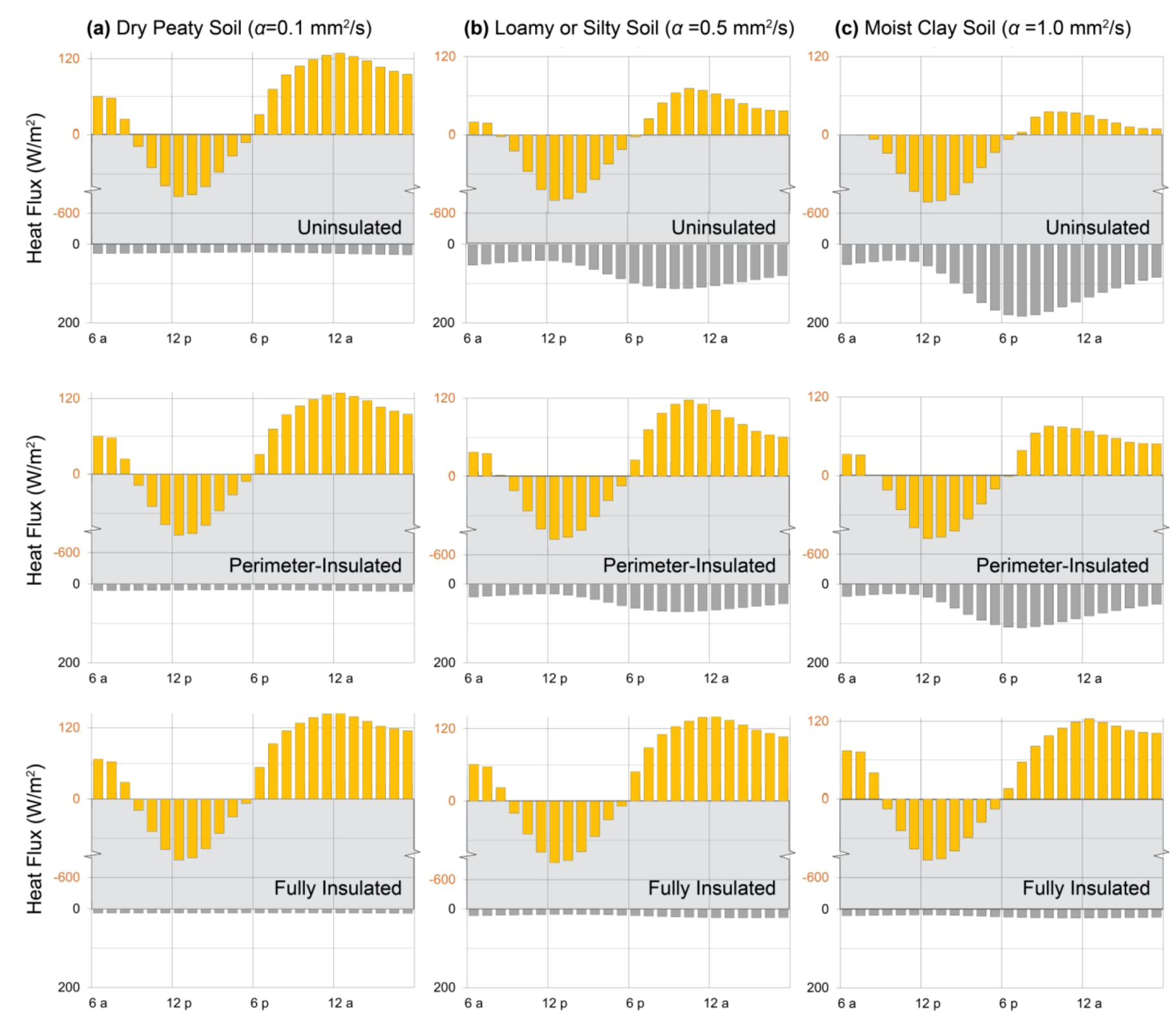
6.1.3. Heat Loss to Soil

While the interior surface of a direct-gain floor contacts only air, collecting and returning heat through radiation and convection, the exterior surface may contact soil, sand, or gravel and lose significant heat by conduction [108,109,110,111]. The problem is intensified if the soil is moist, since soil thermal conductivity increases substantially as pore spaces fill with water [111,112,113]; moreover, fine-grained soils can wick moisture upward from the water table, increasing soil moisture even in locations (e.g., under buildings) that receive no direct precipitation [114].
Perplexingly, however, heat loss through massive thermal storage floors to underlying soils is often addressed (in the U.S.) only at the perimeter [7,12,13,107]: the ASHRAE Handbook of Fundamentals, citing observations that slab-on-grade heat loss is closely related to perimeter length for sufficiently small, unheated slabs, has long recommended only perimeter insulation for all slabs unless radiant heating tubes are buried in the floor [52,115,116]. Massive floors can warm significantly during solar gain, however, creating large enough temperature differences over underlying soil to promote substantial heat loss [24]. Moreover, most building energy simulation tools, including EnergyPlus, use a single “standard” soil thermal diffusivity value from a given weather file, and the common TMY3 files currently provide an unrealistically low soil thermal diffusivity of 0.02 mm2/s [117]. As a result, designers are vulnerable to the belief that perimeter insulation is, indeed, sufficient, when illustrative results below clearly indicate the opposite.

6.1.4. Performance: Direct-Gain Massive Floor
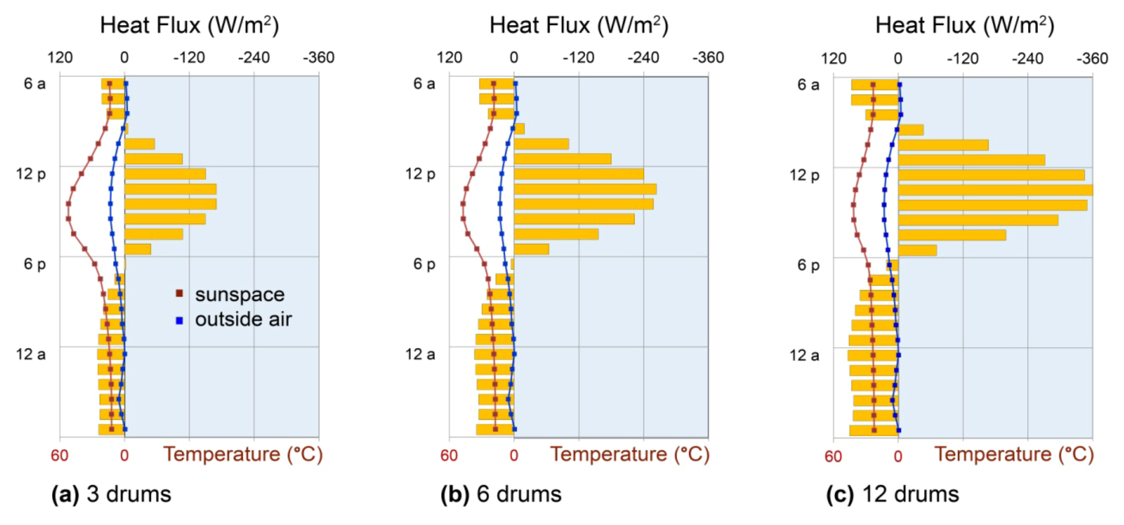
To illustrate the risk of heat loss from direct-gain massive floors to soil, the thermal storage walls of the previous examples were replaced by double clear glazing and a concrete thermal storage floor (Figure 2c). The resulting direct-gain system was simulated, on the same sunny cold day in Denver, Colorado, using a range of representative soil thermal diffusivities. Dry peaty soils have the lowest values likely to be found at building sites, at 0.1 mm2/s; a wide range of silty and loamy soils is represented by the middle value, 0.5 mm2/s; and moist clays have the highest values near 1 mm2/s [109,118].
While the floor over the lowest-diffusivity soil returns more heat overnight than any of the storage walls (Figure 9a, top), even with an equivalent collector area (Section 7), the floor over the medium-diffusivity soil returns less than half that amount (Figure 9b, top), and the floor over the moist clay loses nearly all of its heat to the soil below (Figure 9c, top). Adding perimeter insulation to the latter case, however, only improves it to the performance of the middle case (Figure 9c, middle); full under-slab insulation, equivalent to 2 in. (5 cm) of rigid foam, is necessary to realize heat gains equivalent to those of the initial case (Figure 9c, bottom).
This result illustrates a general benefit of insulation that can be applied, in movable form, to each of the thermal storage walls described above, as well as to the direct-gain glazing itself. After a material, wall thickness, and/or glazing suited to the solar resource and occupant heating needs are selected, movable insulation on tracks or rollers can be deployed to diminish nighttime heat losses to the exterior [7,15,16] or, although seldom mentioned in design guides, to fine-tune heat delivery to the interior.
Figure 9. Direct gain mass floor. Heat fluxes across indoor (upper) and ground (lower) surfaces of 10 cm (4in.) concrete slabs-on-grade over soils with thermal diffusivities of (a) 0.1 mm2/s, representative of a dry peaty soil; (b) 0.5 mm2/s, representative of many silty and loamy soils; and (c) 1.0 mm2/s, representative of a moist clay soil. The top row illustrates patterns characteristic of uninsulated slabs; the middle row adds perimeter R-10 insulation, and the bottom row employs full under-slab R-10 insulation. All models were simulated on a typical sunnyJanuary day in Denver, Colorado. Patterns show the stronginfluence of soil thermal properties on floor thermal storageperformance, particularly when the solar collection surface lies on moist or fine-grained soils.
Geosciences 03 00063 g009

6.2. Sunspaces

Sunspaces are the most flexible in design and versatile in function of the passive solar heating systems. Like direct-gain systems, sunspaces admit solar gains through glass to occupiable space (Figure 2d), but sunspaces are not expected to remain comfortable at all hours: they are attached to, but thermally separate from, occupied space, giving them the freedom to become quite hot during solar collection and quite cool overnight [11,15]. Sunspaces may deliver warm air to occupied space through vents, or they may conduct heat through a massive common wall, such that the sunspace itself becomes analogous to a Trombe wall cavity (Section 5.1). Alternatively, a sunspace may heat only itself, for the benefit of plants, occasional occupancy, and minimization of heat loss from the dwelling. In the latter cases, heat is usually stored in stone, gravel, or concrete floors, or in internal water tanks [7,12,13,29].

6.2.1. Daylight and Plants

Sunspaces are usually constructed with tilted glazing (Figure 2d), increasing solar access and creating brightly daylit spaces with high potential for heat gain. Occupants often fill their sunspaces with plants and comfortable furniture, valuing winter daylight, warmth, and greenness as much as heat delivery to occupied space [24,29,119]. While tilted glazing is essential to both experience and performance, therefore, particularly in cloudy winter climates [24], it increases the risk of overheating on sunny days, which can damage plants [12,29]. Sunspaces with plants have, in effect, no “unoccupied” period during which either overheating or freezing is acceptable, although plants tolerate much wider temperature ranges than humans do. As a result, sunspaces, unlike workplaces, schools, or residences, have valid needs for thermal stability.

6.2.2. Thermal Buffering

An additional vital function of sunspaces, particularly in northern, coastal, and other overcast climates, is the “thermal buffering” of the attached building from heat loss to the outdoors. Simply by maintaining a warmer environment than the outdoors, a passively-heated sunspace diminishes the temperature difference across its common wall(s) and reduces heat loss from those walls accordingly. Sunspaces often enclose entry doors, as well, acting as vestibules to reduce heat loss from conditioned interior space, and they can provide tempered ventilation air to the interior [120,121]. For these purposes, sunspace temperatures are most profitably kept warmest when the temperature difference across the common wall is greatest.

6.2.3. Internal Mass

Sunspaces are often built with massive floors, but like direct-gain floors, they lose heat readily to damp soils (Section 6.1.3, [24]). An effective alternative to under-floor insulation is fully internal mass, i.e., mass that cannot lose heat to the outdoors. Internal mass may take numerous configurations: potted plants, rainwater barrels, fish tanks, stone tables, and earthen fireplaces are all effective, for example [11,12,24]. Among these materials, water is particularly useful because it can collect heat in compact volumes and, despite its thickness, can release heat evenly over many hours (Section 5.2.3).

6.2.4. Performance: Sunspaces with Water Tanks

To illustrate the potential for internal mass to protect sunspace plants from freezing and to buffer conditioned space from heat loss to the outdoors, a 6 m2 (64 sf) sunspace was attached to the building model used in previous examples (Figure 2d) and equipped with three, six, or twelve 208 L (55-gallon) drums of water. The common wall between the building and sunspace was insulated, in this example, and the sunspace temperature was allowed to float freely. Note that the sunspace received greater solar gain than the other configurations, due to its tilted glazing, but that exterior conditions were identical, as the model was simulated for the same sunny January day in Denver, Colorado, and heat flux values were normalized to the total south wall area for comparability with other systems (Section 7).
Plants would have been in danger of frost damage on the night shown, with outside air temperatures dipping below freezing for several hours in the early morning (Figure 10a). Addition of three water drums keeps overnight temperatures 7–10 °C (13–18 °F) warmer overnight, averting the frost problem, but does not prevent daytime overheating, given the relatively low mass of the space. Despite the low mass, however, heat flux from the water drums remains remarkably constant through the night and into the coldest early morning hours (Figure 10a), illustrating the usefulness of internal convection to internal mass performance.
Addition of three further drums, for a total of six, diminishes afternoon high temperatures by 5 °C (9 °F) and increases overnight air temperatures by about the same amount, 5 °C (Figure 10b); another doubling of water storage, to twelve barrels, further reduces afternoon overheating and further warms nighttime hours, increasing heat delivery by about 30% (Figure 10c). This pattern is generally applicable to internal water storage, whether in direct-gain systems or sunspaces: increasing volumes yield increasingly stable temperatures and increasingly great heat return, up to the point where further solar collection is no longer possible, with minimal heat losses to the outdoors.
Figure 10. Sunspace internal mass. Heat fluxes across the surfaces of water-filled, black-painted 208 L (55-gallon) drums (bars), and resulting sunspace air temperatures (squares), using (a) three; (b) six; and (c) twelve drums to store and return heat on a typical sunny January day in Denver, Colorado. Patterns illustrate the consistency of water’s nighttime heat return, driven by internal convection within the barrels, as well as the substantial nighttime and early-morning warming that can be obtained. Sunspaces were thermally uncontrolled, and sunspace floors and internal walls were insulated.
Geosciences 03 00063 g010

7. Building Simulation Methods

To reveal heat storage and release patterns characteristic of material properties and configurations, each strategy was simulated with EnergyPlus 7.1, an open-source building energy simulation program [22]. In the simulations, each strategy served a south-facing one-room building, 6.1 m (20 ft) long in the E-W direction and 4.6 m (15 ft) deep in the N-S direction, with a shed roof sloped from 3 m (10 ft) on the south to 2.4 m (8 ft) on the north (resembling sections in Figure 2). Batt-insulated wood stud construction was assumed for the roof and walls (R-19), and the floor was thermally isolated from the ground, except in the direct-gain example, for simplicity of data interpretation. Infiltration was assumed to be moderate at 1.0 air changes per hour (ACH) in all spaces, including the sunspace (Section 6.2), and interior temperatures were kept from dropping below 20 °C (68 °F) by backup heat.
Building geometry was defined with OpenStudio 1.0.8, a Google SketchUp 8 plug-in for EnergyPlus [122]. Glazing assembly properties were calculated by WINDOW6.3 [123] and referenced by EnergyPlus; all other objects (materials, constructions, schedules, internal mass, soil characteristics, infiltration) were specified directly with the EnergyPlus IDF Editor [22].
For illustrative purposes, it was necessary to choose a specific set of outdoor conditions; Denver, Colorado on January 15 of the Typical Meteorological Year 3 (TMY3) weather file [117] provided ideal conditions for comparison because of its clear sky, appreciable solar radiation, cold outdoor temperatures, and low sun angles. While the heat flux patterns shown, and their responses to varied parameters, are valid in general, the quantities of heat stored and released depend on the incident solar radiation and outdoor temperatures of the day and location simulated.
Trombe walls were simulated using the “TrombeWall” Zone Inside Convection Algorithm to represent air convection within each cavity [124]. Temperature-dependent enthalpies of phase-change materials were described with “MaterialProperty:PhaseChange” objects, capturing latent heats of fusion, and “MaterialProperty:VariableThermalConductivity” objects were used to describe temperature-dependent thermal conductivities. In direct-gain and sunspaces, building solar distribution was simulated with the “FullInteriorAndExteriorWithReflections” model, in which beam solar radiation is projected through glazing to the correct zone surface and absorbed or reflected accordingly, rather than assumed by default to fall on the floor. Soil temperatures, for the direct-gain simulation, were derived from the Denver TMY3 weather file using the SLAB preprocessor to estimate monthly average ground temperatures under the slab perimeter and core [125]. For water walls and drums, correlations between Rayleigh and Nusselt numbers were used to quantify convective contributions to heat transfer (Section 5.2), which were incorporated as effective thermal conductivities. Other simulation details are contained within the respective sections.

8. Conclusions

Returning to the ideal heat flux profiles, tailored to deliver residential evening heating, daytime workplace heating, all-night heating for plants or thermal buffering, and cooling, respectively (Figure 1), we see that specific materials, in specific configurations, characteristically store and deliver heat in the patterns needed.
Residential evening heating calls for heat to be stored many hours earlier than it is released, and then to be delivered to living spaces fairly promptly, before occupants go to sleep (Figure 1a). Direct-gain floors deliver substantial evening heat, if insulated from soil (Figure 9), as do Trombe walls (Figure 5b–d), followed by gradual declines in delivery through the night; movable insulation over Trombe wall interiors may be used to avoid afternoon heating, if desired, and wall thickness should be chosen to deliver the amplitude of heat desired in the climate and season of greatest importance.
Daytime heating, in contrast, requires heat to be delivered soon after it is collected (Figure 1b). One might reasonably wonder why heat would be stored at all, for daytime use, rather than simply admitted directly to occupied space; however, workspaces are not well-suited to direct solar exposure because of the potential for glare and overheating. Fortunately, water provides a rapid storage-and-delivery system that can be deployed in thin external walls (insulated overnight, ideally, to minimize losses) (Figure 6a) or in thin Trombe water walls (Figure 6b). Thin stone and concrete Trombe walls also deliver heat soon after collection, and as for evening heating, thickness can be chosen specifically to provide the best possible combination of amplitude and timing of heat delivery (compare Figure 4b,c and Figure 5).
All-night heating with exceptional evenness is the province of thick Trombe water walls (Figure 6b), substantial water internal mass (Figure 10), and thin Trombe-PCM walls (Figure 8); PCMs can also be used as internal mass in thin tubes (Section 5.3). The internal convection possible in water, and the extraordinary latent heat storage possible in PCMs, each allow heat to be brought continually to container boundaries for release to cooler space. Cooling, finally, is possible with any material of high thermal effusively, allowing it to absorb heat readily from warm interiors as well as warm exteriors, but low thermal diffusivity, delaying the transmission of external heat to the interior. Earth, brick, stone, and concrete are all candidates (Table 1). As vernacular architecture suggests (Section 4.1), and as indicated by Figure 4, these should be deployed in thick configurations, without glazing or insulation, to maximize nighttime losses to the outdoors.
While passive systems cannot provide the instant heat or cooling of a mechanical switch, they are nevertheless highly adjustable by variation of material, thickness, and configuration, as illustrated above, and therefore tunable to occupant needs. Moreover, patterns of heat uptake, storage, and delivery vary in characteristic, reproducible ways with material and thickness, allowing them to be incorporated into early stages of design. Architects and builders should no longer accept conventional wisdom, applied too broadly and with goals too limited, regarding thermal storage sizing (Section 2), because an intuitive understanding of thermal storage performance is within reach of every designer and engineer. A great opportunity now exists, therefore, not only to improve case-by-case thermal storage design, but to establish a new, geologically-inspired design wisdom in the process.

Acknowledgments

We gratefully acknowledge the encouragement and influence of passive solar pioneers John Reynolds and G.Z. Brown, of the University of Oregon, and David Bainbridge and Ken Haggard of the San Luis Obispo Sustainability Center. Walter Grondzik, currently of Ball State University, and architects Howard Davis of Eugene and Catherine Young of Ventura, California were instrumental to our early studies of thermal mass in passive solar buildings. Designer Ken Gates has supported our research extensively with built sunspaces to test our ideas, and geologist and passive solar experimentalist Katharine Cashman has provided numerous challenging discussions. We additionally thank our anonymous reviewers for their insight, rigor, and enthusiasm.

References

  1. Butti, K.; Perlin, J. A Golden Thread: 2500 Years of Solar Architecture and Technology; Cheshire Books: Palo Alto, CA, USA, 1980; pp. 7–27, 156–179, 235. [Google Scholar]
  2. McHenry, P.G. Adobe and Rammed Earth Buildings: Design and Construction; John Wiley & Sons: New York, NY, USA, 1984; pp. 1–112. [Google Scholar]
  3. Fardeheb, F. Examination and Review of Passive Solar Cooling Strategies in Middle Eastern and North African Vernacular Architecture. In Proceedings of the International Solar Energy Society World Congress, Beijing, China, 18–21 September 2007.
  4. Christenson, A.L. The microenvironment of cliff dwellings in Tsegi Canyon, Arizona. Kiva 1991, 57, 39–54. [Google Scholar]
  5. Hastings, S.R.; Wall, M. Sustainable Solar Housing: Strategies and Solutions; Earthscan: London, UK, 2007; pp. 1–3. [Google Scholar]
  6. Balcomb, J.D. Introduction. In Passive Solar Buildings; Balcomb, J.D., Ed.; MIT Press: Cambridge, MA, USA, 1992; pp. 1–38. [Google Scholar]
  7. Mazria, E. The Passive Solar Energy Book; Rodale Press: Emmaus, PA, USA, 1979; pp. 28–35, 51, 133–171, 181–185, 231–239, 311. [Google Scholar]
  8. Boyer, L.L. Earth shelter goes international. In Renewable Energy, Renewable Living: International Interests; American Solar Energy Society: Boulder, CO, USA, 1983; pp. 549–643. [Google Scholar]
  9. Niles, P.W.B.; Haggard, K. Passive Solar Handbook; California Energy Commission: Sacramento, CA, USA, 1980; pp. 91, 209. [Google Scholar]
  10. Wilson, A. Passive solar heating. Environ. Build. News 2012, 21, 1–15. [Google Scholar] [CrossRef]
  11. Bainbridge, D.A.; Haggard, K. Passive Solar Architecture; Chelsea Green Publishing: White River Junction, VT, USA, 2011; pp. 33, 58–74. [Google Scholar]
  12. Stein, B.; Reynolds, J.S.; Grondzik, W.T.; Kwok, A.G. Mechanical and Electrical Equipment for Buildings, 10th ed; John Wiley & Sons: New York, NY, USA, 1609; pp. 223–235 ,259–265, 275, 1582–1583, 1609. [Google Scholar]
  13. Lechner, N. Heating, Cooling, and Lighting: Design Methods for Architects, 3rd ed; John Wiley & Sons: New York, NY, USA, 2009; pp. 141–175, 477–478. [Google Scholar]
  14. Chiras, D.D. The Solar House: Passive Heating and Cooling; Chelsea Green Publishing: White River Junction, VT, USA, 2002; pp. 28–29, 102–105. [Google Scholar]
  15. Brown, G.Z.; DeKay, M. Sun, Wind & Light: Architectural Design Strategies; John Wiley & Sons: New York, NY, USA, 2001; pp. 169, 172–175, 230–231, 258–259. [Google Scholar]
  16. Stephen Winter Associates, The Passive Solar Design and Construction Handbook; Crosbie, M. (Ed.) John Wiley & Sons: New York, NY, USA, 1998; pp. 38–41, 113–121, 256–266.
  17. Salazar, A. On thermal diffusivity. Eur. J. Phys. 2003, 24, 351–358. [Google Scholar] [CrossRef]
  18. Clauser, C.; Huenges, E. Thermal conductivity of rocks and minerals. In Rock Physics and Phase Relations—A Handbook of Physical Constants; Ahrens, T.J., Ed.; American Geophysical Union: Washington, DC, USA, 1995; Volume 3, pp. 105–126. [Google Scholar]
  19. Kuznik, F.; David, D.; Johannes, K.; Roux, J.-J. A review on phase change materials integrated in building walls. Renew. Sustain. Energy Rev. 2011, 15, 379–391. [Google Scholar] [CrossRef]
  20. Sharma, A.; Tyagi, V.V.; Chen, C.R.; Buddhi, D. Review on thermal energy storage with phase change materials and applications. Renew. Sustain. Energy Rev. 2009, 13, 318–345. [Google Scholar] [CrossRef]
  21. Zhou, D.; Zhao, C.Y.; Tian, Y. Review on thermal energy storage with phase change materials (PCMs) in building applications. Appl. Energy 2012, 92, 593–605. [Google Scholar] [CrossRef] [Green Version]
  22. EnergyPlus Energy Simulation Software; Office of Energy Efficiency and Renewable Energy, U.S. Department of Energy, 2012. Available online: http://apps1.eere.energy.gov/buildings/energyplus/ (accessed on 16 October 2012).
  23. Niles, P.W.B. Simulation analysis. In Passive Solar Buildings; Balcomb, J.D., Ed.; MIT Press: Cambridge, MA, USA, 1992; pp. 111–180. [Google Scholar]
  24. Rempel, A.R.; Rempel, A.W.; Cashman, K.V.; Gates, K.N.; Page, C.J.; Shaw, B. Interpretation of passive solar field data with EnergyPlus models: Un-conventional wisdom from four sunspaces in Eugene, Oregon. Build. Env. 2013, 60, 158–172. [Google Scholar] [CrossRef]
  25. Sharag-Eldin, A.; Bergman, G. Using Energy-10 to Determine Thermal Comfort Conditions in Anasazi Pit Dwellings. In Proceedings of the American Solar Energy Society Annual Conference, Washington, DC, USA, 21–25 April 2001; pp. 503–510.
  26. Balcomb, J.D.; Barley, D.; McFarland, R.; Perry, J.; Wray, W.; Noll, S. Sensitivity analysis of thermal storage walls. In Passive Solar Design Handbook, Part Two: Passive Solar Design Analysis; Los Alamos National Laboratory: Los Alamos, NM; University of California: Berkeley, CA, USA, 1984; pp. 86–105. [Google Scholar]
  27. ANSI/ASHRAE/IESNA Standard 90.1-2010: Energy Standard for Buildings Except Low-Rise Residential Buildings; American Society of Heating, Refrigerating, and Air-Conditioning Engineers: Atlanta, GA, USA, 2010.
  28. Holtz, M.J. Commercial building integration. In Passive Solar Buildings; Balcomb, J.D., Ed.; MIT Press: Cambridge, MA, USA, 1992; pp. 364–388. [Google Scholar]
  29. Shapiro, A.M. Add-on Solar Greenhouses & Sunspaces; Rodale Press: Emmaus, PA, USA, 1985; pp. 56–68, 79–112. [Google Scholar]
  30. Braun, J.E.; Montgomery, K.W.; Chaturvedi, N. Evaluating the performance of building thermal mass control strategies. HVAC&R Res. 2001, 7, 403–428. [Google Scholar]
  31. Kachadorian, J. The Passive Solar House; Chelsea Green Publishing: White River Junction, VT, USA, 1997; pp. 31–33. [Google Scholar]
  32. Anderson, B. Thermal storage walls. In Passive Solar Design Handbook; Van Nostrand Reinhold: New York, NY, USA, 1984; pp. 22–31, 41–51. [Google Scholar]
  33. Balcomb, J.D.; Jones, R.W.; McFarland, R.D.; Wray, W.O. The monthly SLR method. In Passive Solar Heating Analysis; Los Alamos National Laboratory: Los Alamos, NM; American Society for Heating, Refrigerating, and Air-Conditioning Engineers: Atlanta, GA, USA, 1980; pp. 8–1. [Google Scholar]
  34. Balcomb, J.D.; Barley, D.; McFarland, R.; Perry, J.; Wray, W.; Noll, S. Estimating temperature swings in direct-gain buildings. In Passive Solar Design Handbook; Van Nostrand Reinhold: New York, NY, USA, 1984; pp. 106–113. [Google Scholar]
  35. Balcomb, J.D.; Jones, R.W.; McFarland, R.D.; Wray, W.O. The load coefficients. In Passive Solar Heating Analysis; Los Alamos National Laboratory: Los Alamos, NM; American Society for Heating, Refrigerating, and Air-Conditioning Engineers: Atlanta, GA, USA, 1980; pp. 3–1. [Google Scholar]
  36. Balcomb, J.D.; Jones, R.W.; McFarland, R.D.; Wray, W.O. Degree-days and base temperature. In Passive Solar Heating Analysis; Los Alamos National Laboratory: Los Alamos, NM; American Society for Heating, Refrigerating, and Air-Conditioning Engineers: Atlanta, GA, 1980; pp. 4–1. [Google Scholar]
  37. National Climatic Data Center. NOAA 1981–2010 Climate Normals. Available online: http://www.ncdc.noaa.gov/oa/climate/normals/usnormals.html (accessed on 1 November 2012).
  38. Newcomb, D. The Owner-Built Adobe House; University of New Mexico Press: Albuquerque, NM, USA, 2001; pp. 11, 35–48. [Google Scholar]
  39. Minke, G. Building with Earth: Design and Technology of a Sustainable Architecture, 2nd ed; Birkhauser: Boston, MA, USA, 2009; pp. 30–32. [Google Scholar]
  40. Revuelta-Acosta, J.D.; Garcia-Diaz, A.; Soto-Zarazua, G.M.; Rico-Garcia, E. Adobe as a sustainable material: A thermal performance. J. Appl. Sci. 2010, 10, 2211–2216. [Google Scholar] [CrossRef]
  41. Trombe, F.; Robert, J.F.; Cabanot, M.; Sesolis, B. Concrete walls to collect and hold heat. Sol. Age 1977, 2, 13–19. [Google Scholar]
  42. Wilson, A. Thermal Storage Wall Design Manual; New Mexico Solar Energy Association: Albuquerque, NM, USA, 1979. [Google Scholar]
  43. Quesada, G.; Rousse, D.; Dutil, Y.; Badache, M.; Halle, S. A comprehensive review of solar facades: Opaque solar facades. Renew. Sustain. Energy Rev. 2012, 16, 2820–2832. [Google Scholar] [CrossRef]
  44. Koyunbaba, B.K.; Yilmaz, Z. A comparison of Trombe wall systems with single glass, double glass and PV panels. Renew. Energy 2012, 45, 111–118. [Google Scholar] [CrossRef]
  45. Gan, G. A parametric study of Trombe walls for passive cooling of buildings. Energy Build. 1998, 27, 37–43. [Google Scholar]
  46. Alvarado, J.L.; Terrell, W.; Johnson, M.D. Passive cooling systems for cement-based roofs. Build. Environ. 2009, 44, 1869–1875. [Google Scholar] [CrossRef]
  47. Ballinger, A.; Oppenheim, D.; Ramachandran, A. National Design Handbook Prototype on Passive Solar Heating and Natural Cooling of Buildings; United Nations Centre for Human Settlements (Habitat): Nairobi, Kenya, 1990; pp. 42–43, 88–90. [Google Scholar]
  48. Engel, T.; Reid, P. Thermodynamics, Statistical Thermodynamics, and Kinetics, 2nd ed; Pearson: Upper Saddle River, NJ, USA, 2010; pp. 359–372. [Google Scholar]
  49. Kaviany, M. Principles of Heat Transfer; Wiley: New York, NY, USA, 2002; pp. 175–183, 269–275, 899–955. [Google Scholar]
  50. Riedi, P.C. Thermal Physics, 2nd ed; Oxford: New York, NY, USA, 1988; pp. 247–261. [Google Scholar]
  51. Carslaw, H.S.; Jaeger, J.C. Conduction of Heat in Solids, 2nd ed; Clarendon Press: Oxford, UK, 1959; pp. 1–49. [Google Scholar]
  52. Owen, M.S.; Kennedy, H.E. ASHRAE Handbook: Fundamentals; American Society of Heating, Refrigerating, and Air-Conditioning Engineers: Atlanta, GA, USA, 2005; pp. 24.1–24.16, 39.2–39.4. [Google Scholar]
  53. Yener, Y.; Kakac, S. Heat Conduction, 4th ed; Taylor & Francis: New York, NY, USA, 2008; pp. 20–22. [Google Scholar]
  54. Evers, A.C.; Medina, M.A.; Fang, Y. Evaluation of the thermal performance of frame walls enhanced with paraffin and hydrated salt phase change materials using a dynamic wall simulator. Build. Environ. 2010, 45, 1762–1768. [Google Scholar] [CrossRef]
  55. Abhat, A. Low temperature latent heat thermal energy storage: Heat storage materials. Sol. Energy 1983, 30, 313–332. [Google Scholar] [CrossRef]
  56. Lane, G.A. Low temperature heat storage with phase change materials. Int. J. Ambient Energy 1980, 1, 155–168. [Google Scholar] [CrossRef]
  57. Lertwattanaruk, P.; Choksiriwanna, J. The physical and thermal properties of adobe brick containing bagasse for earth construction. Built 2011, 1, 54–61. [Google Scholar]
  58. Allinson, D.; Hall, M. Hygrothermal analysis of a stabilised rammed earth test building in the UK. Energy Build. 2010, 42, 845–852. [Google Scholar] [CrossRef]
  59. Yan, Z.; Lam, J.C.; Liu, J. Experimental studies on the thermal and moisture properties of rammed earth used in adobe buildings in China. Archit. Sci. Rev. 2005, 48, 55–60. [Google Scholar] [CrossRef]
  60. Du, S.; Ma, J.; Wang, D. Experimental research on thermal and mechanical properties of modified rammed earth material. Adv. Mater. Res. 2012, 450–451, 773–777. [Google Scholar] [CrossRef]
  61. Soebarto, V. Analysis of Indoor Performance of Houses Using Rammed Earth Walls. In Building Simulation 2009, Proceedings of the 11th International IBPSA Conference, Glasgow, UK, 27–30 July 2009.
  62. Mehta, P.K.; Monteiro, P.J.M. Concrete: Microstructure, Properties, and Materials; McGraw-Hill: New York, NY, USA, 2006; pp. 3–19, 114–120. [Google Scholar]
  63. Olhoeft, G.R.; Johnson, G.R. Densities of rocks and minerals. In CRC Practical Handbook of Physical Properties of Rocks and Minerals; Carmichael, R.S., Ed.; CRC Press: Boca Raton, FL, USA, 1989; pp. 141–176. [Google Scholar]
  64. Winkler, E.M. Stone in Architecture: Properties, Durability, 3rd ed; Springer-Verlag: New York, NY, USA, 1994; pp. 32–62. [Google Scholar]
  65. Kobranova, V.N. Petrophysics [Translated by Kuznetsov, V.V.]; Springer-Verlag: New York, NY, USA, 1989; pp. 193–222. [Google Scholar]
  66. Robertson, E.C. Thermal Properties of Rocks; Open File Report 88-441 of USGS: Reston, VA, USA, 1988. [Google Scholar]
  67. Mellon, M.T.; Jakosky, B.M.; Kieffer, H.H.; Christensen, P.R. High-resolution thermal inertia mapping from the Mars Global Surveyor Thermal Emission Spectrometer. Icarus 2000, 148, 437–455. [Google Scholar] [CrossRef]
  68. Heat, Air, and Moisture Laboratory. Impact of Thermal Diffusivity and Thermal Effusivity; Department of the Built Environment, Technische Universiteit Eindhoven: Eindhoven, NL, USA, 2010. Available online: http://archbps1.campus.tue.nl/bpswiki/images/5/5b/H1.pdf (accessed on 1 October 2012).
  69. Wright, J.L. A correlation to quantify convective heat transfer between vertical window glazings. ASHRAE Trans. 1996, 102, 940–946. [Google Scholar]
  70. Zhao, Y.; Curcija, D.; Goss, W.P. Convective heat transfer correlations for fenestration glazing cavities: A review. ASHRAE Trans. 1999, 105, 900–908. [Google Scholar]
  71. Dobson, S. Continuity of tradition: New earth building. In Terra 2000; Keynote Address: Torquay, UK, May 2000. [Google Scholar]
  72. Norton, J. Building with Earth: A Handbook, 2nd ed; Intermediate Technology Publications: London, UK, 1997; pp. 4–5, 28, 43. [Google Scholar]
  73. Campbell, J.W.P.; Pryce, W. Brick: A World History; Thames & Hudson: London, UK, 2003; pp. 13, 30–33, 50, 215–217. [Google Scholar]
  74. Tiller, T.P.; Look, D.W. Preservation of historic adobe buildings. In Preservation Briefs; No. 5; U.S. Department of the Interior: Washington, DC, USA, 1978; pp. 1–8. [Google Scholar]
  75. Binici, H.; Aksogan, O.; Nuri, B.M.; Akca, E.; Kapur, S. Thermal isolation and mechanical properties of fibre reinforced mud bricks as wall materials. Constr. Build. Mater. 2007, 21, 901–906. [Google Scholar] [CrossRef]
  76. Southwick, M. Build with Adobe; Sage Books: Chicago, IL, USA, 1966; pp. 2–3. [Google Scholar]
  77. Maniatidis, V.; Walker, P. A Review of Rammed Earth Construction; DTi Partners in Innovation Project “Developing Rammed Earth for UK Housing”: Bath, UK, 2003. [Google Scholar]
  78. Easton, D. The Rammed Earth House; Chelsea Green Publishing Company: White River Junction, VT, USA, 2007; pp. 3–37. [Google Scholar]
  79. Goodhew, S.; Griffiths, R. Sustainable earth walls to meet the building regulations. Energy Build. 2005, 37, 451–459. [Google Scholar] [CrossRef]
  80. Cultrone, G.; Sebastian, E.; Elert, K.; de la Torre, M.J.; Cazalla, O.; Rodriguez-Navarro, C. Influence of mineralogy and firing temperature on the porosity of bricks. J. Eur. Ceram. Soc. 2004, 24, 547–564. [Google Scholar] [CrossRef]
  81. Alden, A. The Geology of Bricks. Available online: http://geology.about.com/od/mineral_resources/a/bricks.htm (accessed on 1 November 2012).
  82. Brick Passive Solar Heating Systems, Part 4: Material Properties; Technical Note on Brick Construction 43D; Brick Industry Association: Reston, VA, USA, 1988; pp. 1–13.
  83. Beall, C. Masonry Design and Detailing: for Architects, Engineers, and Contractors, 3rd ed; McGraw-Hill: New York, NY, USA, 1993; pp. 89–105. [Google Scholar]
  84. Winkler, E.M. Stone: Properties, Durability in Man’s Environment, 2nd ed; Springer-Verlag: New York, NY, USA, 1975; pp. 102–168, 198–202. [Google Scholar]
  85. Murton, J.B.; Peterson, R.; Ozouf, J.-C. Bedrock fracture by ice segregation in cold regions. Science 2006, 314, 1127–1129. [Google Scholar] [CrossRef]
  86. Kim, K.-H.; Jeon, S.-E.; Kim, J.-K.; Sungchul, Y. An experimental study on thermal conductivity of concrete. Cem. Concr. Res. 2003, 33, 363–371. [Google Scholar]
  87. Ellis, P.G. Development and Validation of the Unvented Trombe Wall Model in EnergyPlus.
  88. Ellis, P.G.; Liesen, R.J.; Pedersen, C.O. Energyplus Experimental Data Validation Work: Development and Validation of the Unvented Trombe Wall Model and Other Heat Balance Components; Final Report DACA42-01-D-0004, Task 3; U.S. Army Construction Engineering Research Laboratory: Champaign, IL, USA, 2003. [Google Scholar]
  89. Chan, H.-Y.; Riffat, S.B.; Zhu, J. Review of passive solar heating and cooling technologies. Renew. Sustain. Energy Rev. 2010, 14, 781–789. [Google Scholar] [CrossRef]
  90. Gordon, J.M. Selective coatings in passive solar heating. Sol. Energy 1982, 29, 13–17. [Google Scholar] [CrossRef]
  91. Goswami, D.Y.; Kreith, F.; Kreider, J.F. Passive methods for heating, cooling, and daylighting. In Principles of Solar Engineering, 2nd ed; Taylor & Francis: Philadelphia, PA, USA, 2000; pp. 297–336, 655–676. [Google Scholar]
  92. Shelby, J.E. Introduction to Glass Science and Technology, 2nd ed; Royal Society of Chemistry: Cambridge, UK, 2005; pp. 202–221. [Google Scholar]
  93. Torcellini, P.; Pless, S. Trombe Walls in Low-Energy Buildings: Practical Experiences; NREL/CP-550-36277; National Renewable Energy Laboratory: Golden, CO, USA, 2004. [Google Scholar]
  94. Torcellini, P.; Long, N.; Pless, S.; Judkoff, R. Evaluation of the Low-Energy Design and Energy Savings of the Zion National Park Visitors Center; NREL/TP-550-34607; National Renewable Energy Laboratory: Golden, CO, USA, 2005. [Google Scholar]
  95. Fernandez-Gonzalez, A. Analysis of the thermal performance and comfort conditions produced by five different passive solar heating strategies in the United States Midwest. Sol. Energy 2007, 81, 581–593. [Google Scholar] [CrossRef]
  96. Churchill, S.W.; Chu, H.H.S. Correlating equations for laminar and turbulent free convection from a vertical plate. Int. J. Heat Mass Transf. 1975, 18, 1323–1329. [Google Scholar] [CrossRef]
  97. Cabeza, L.F.; Castrell, A.; Barreneche, C.; de Gracia, A.; Fernandez, A.I. Materials used as PCM inthermal energy storage in buildings: A review. Renew. Sustain. Energy Rev. 2011, 15, 1675–1695. [Google Scholar]
  98. Telkes, M. Trombe Wall with Phase Change Storage Material. In Proceedings of the National Passive Solar Conference, Philadelphia, PA, USA, 16–18 March 1978; II, p. 271.
  99. Pasupathy, A.; Velraj, R.; Seeniraj, R.V. Phase change material-based building architecture for thermal management in residential and commercial establishments. Renew. Sustain. Energy Rev. 2008, 12, 39–64. [Google Scholar] [CrossRef]
  100. Tyagi, V.V.; Buddhi, D. PCM thermal storage in buildings: A state of art. Renew. Sustain. Energy Rev. 2007, 11, 1146–1166. [Google Scholar] [CrossRef]
  101. Ure, Z. Phase Change Material (PCM) Based Energy Storage Materials and Global Application Examples. In Proceedings of CIBSE Technical Symposium 2011, Leicester, UK, 6–7 September 2011.
  102. Negi, A.S.; Anand, S.C. A Textbook of Physical Chemistry; Wiley Eastern: New Delhi, India, 1985; pp. 459–461. [Google Scholar]
  103. Feltham, D.H.; Untersteiner, N.; Wettlaufer, J.S.; Worster, M.G. Sea ice is a mushy layer. Geophys. Res. Lett. 2006, 33, L14501:1–L14501:4. [Google Scholar]
  104. Huppert, H.E.; Worster, M.G. Dynamic solidification of a binary alloy. Nature 1985, 314, 703–707. [Google Scholar]
  105. Feichenfeld, H.; Sarig, S. Calcium chloride hexahydrate: A phase changing material for energy storage. Ind. Eng. Chem. Prod. Res. Dev. 1985, 24, 130–133. [Google Scholar] [CrossRef]
  106. Millard, E.B. Physical Chemistry for Colleges: A Course of Instruction Based Upon the Fundamental Laws of Chemistry; McGraw-Hill: New York, NY, USA, 1921; p. 289. [Google Scholar]
  107. Balcomb, J.D.; Barley, D.; McFarland, R.; Perry, J.; Wray, W.; Noll, S. Direct gain. In Passive Solar Design Handbook; Van Nostrand Reinhold: New York, NY, USA, 1984; pp. 153–173. [Google Scholar]
  108. Krarti, M. Effect of spatial variation of soil thermal properties on slab-on-ground heat transfer. Build. Environ. 1996, 31, 51–57. [Google Scholar] [CrossRef]
  109. Arya, S.P. Soil temperatures and heat transfer. In Introduction to Micrometeorology, 2nd ed; Academic Press: San Diego, CA, USA, 2001; pp. 46–61. [Google Scholar]
  110. Chuangchid, P.; Krarti, M. Foundation heat loss from heated concrete slab-on-grade floors. Build. Environ. 2001, 36, 637–655. [Google Scholar] [CrossRef]
  111. Deru, M. A Model for Ground-coupled Heat and Moisture Transfer from Buildings; Report No. NREL/TP-550-33954; National Renewable Energy Laboratory: Golden, CO, USA, 2003. [Google Scholar]
  112. Janssen, H.; Carmeliet, J.; Hens, H. Influence of soil moisture transfer on building heat loss via the ground. Build. Environ. 2004, 39, 825–836. [Google Scholar] [CrossRef]
  113. Farouki, O.T. Thermal Properties of Soils; Report No. CRREL Monograph 81-1; U.S. Army Corps of Engineers Cold Regions Research and Engineering Laboratory: Hanover, NH, USA, 1981. [Google Scholar]
  114. Dingman, S.L. Water in soils: Infiltration and redistribution. In Physical Hydrology, 2nd ed; Prentice-Hall: Upper Saddle River, NJ, USA, 2002; pp. 220–264. [Google Scholar]
  115. Bahnfleth, W.P. Three-Dimensional Modelling of Heat Loss from Slab Floors; Report No. USACERL Technical Manuscript E-89/11; U.S. Army Corps of Engineers Cold Regions Research and Engineering Laboratory: Hanover, NH, USA, 1989. [Google Scholar]
  116. Kusuda, T.; Bean, J.W. Simplified methods for determining seasonal heat loss from uninsulated slab-on-grade floors. ASHRAE Transactions 1984, 90, 611–632. [Google Scholar]
  117. National Renewable Energy Laboratory Web Page. National Solar Radiation Data Base 1991–2005 Update: Typical Meteorological Year 3. 2005. Available online: http://rredc.nrel.gov/solar/old_data/nsrdb/1991-2005/tmy3/ (accessed on 2 November 2012).
  118. Tarnawski, V.R.; Wagner, B. A new computerized approach to estimating the thermal properties of unfrozen soils. Can. Geotech. J. 1992, 29, 714–720. [Google Scholar] [CrossRef]
  119. Anderson, B.; Wells, M. Passive Solar Energy: The Homeowner’s Guide to Natural Heating and Cooling, 2nd ed; Brick House Publishing Company: Amherst, NH, USA, 1994; pp. 33–46. [Google Scholar]
  120. MacGregor, A.W.K. A Comparison of the Climatic Suitability of Various Locations in the European Community for Solar Space Heating. In Proceedings ofthe World Solar Forum, Brighton, UK, 23–28 August 1981; pp. 1852–1857.
  121. Porteous, C.; MacGregor, A.W.K. Latitude myths challenged. In Solar Architecture in Cool Climates; Porteous, C., MacGregor, A.W.K., Eds.; Earthscan Publishers: London, UK, 2005; pp. 2–5. [Google Scholar]
  122. Legacy OpenStudio Plug-in for Google SketchUp, version 1.0.9; Office of Energy Efficiency and Renewable Energy, U.S. Department of Energy: Washington, DC, USA, 2012. Available online: http://apps1.eere.energy.gov/buildings/energyplus/openstudio.cfm (accessed on 16 October 2012).
  123. WINDOW 6.3: Complex Glazing System Modeling; Lawrence Berkeley National Laboratory: Berkeley, CA, USA, 2012. Available online: http://windows.lbl.gov/software/window/window.html (accessed on 16 October 2012).
  124. EnergyPlus 7.1 Engineering Reference; Office of Energy Efficiency and Renewable Energy, U.S. Department of Energy: Washington, DC, USA, 2012. Available online: http://apps1.eere.energy.gov/buildings/energyplus/pdfs/engineeringreference.pdf (accessed on 20 October 2012).
  125. Auxiliary EnergyPlus Programs; Office of Energy Efficiency and Renewable Energy, U.S. Department of Energy: Washington, DC, USA, 2012. Available online: http://apps1.eere.energy.gov/buildings/energyplus/pdfs/auxiliaryprograms.pdf (accessed on 16 October 2012).

