Article

Selection of Colloidal Silica Grouts with Respect to Gelling and Erosion Behaviour

Department of Engineering Science, University of Oxford, Parks Road, Oxford OX1 3PJ, UK
*
Author to whom correspondence should be addressed.
Geosciences 2017, 7(1), 6; https://doi.org/10.3390/geosciences7010006
Submission received: 4 October 2016 / Revised: 16 January 2017 / Accepted: 22 January 2017 / Published: 6 February 2017

Abstract

:
Cembinder, Eka EXP36, and MEYCO MP320 are three colloidal silica materials that have been proposed for post-excavation grouting of deep tunnels in a radioactive waste repository. In this study, samples of these colloidal silicas were tested for their particle size distribution, gel induction time (tG), gel time (TG), and physical erosion, under mildly saline groundwater flow conditions. In order to achieve a desired gel time range, from 15 to 50 min, it is recommended that the colloidal silica is mixed with a NaCl accelerator at a 5:1 volume ratio. At 20 °C, the concentration range for the NaCl solution should be 1.5 to 1.7 M for MEYCO, 1.23 to 1.38 M for Eka EXP36, and 1.3 to 1.47 M for Cembinder. The physical erosion of the set silicas remained steady during a 10 h flow cell experiment, when grouts were subjected to 0.05 M NaCl at a superficial velocity of 2.2 × 10⁻⁵ m/s. For these test conditions, the results show that MEYCO has the highest average erosion rate (0.85 mg/h) of the three grout materials, as well as the greatest variability in this rate. Cembinder performed best with the lowest silica removal rate. Extrapolation of the measured erosion rates suggests that grout fracture dilation would not be significant under natural quiescent groundwater flow conditions, but would be high if there was hydraulic communication between the geosphere and the repository.

1. Introduction

High-level waste (HLW) and spent fuel (SF) are produced as part of nuclear power plant operation [1]. Geological disposal sites for these wastes have been established across Europe, Asia, and North America. As part of the “Engineered Barrier System”, these wastes are disposed in tunnels excavated at approximately 650 m below the earth’s surface, and deep tunnel grouting may be required as a component of the engineered barrier system. Grouting is proposed as a post-excavation activity, i.e., after tunnel excavation. Grouts are injected under pressure, until fractures are effectively sealed, the permeability of the rock mass is reduced [2], and the seepage is within specification limits.
Rock fractures vary in the opening width and lateral extent; different grouts have been selected, depending on their penetrative ability. For current design concepts, it is not permitted to use normal Portland cement grouts for radioactive waste storage below a depth of 290 m, where hard rocks are saturated with groundwater. This is because high-pH pore fluid, leached from normal cement, will affect the performance of the inner bentonite barrier [3]. Instead, low-pH cementitious (cement-based) grouts are proposed for sealing fractures/fissures of widths >100 µm, and non-cementitious colloidal silica grouts are proposed for sealing smaller fractures (<100 µm).
Colloidal silica grouts are stable sols of colloidal silica, but when mixed with an accelerator (NaCl), they set. The setting can be explained by DLVO theory, (Derjaguin, Landau, Verwey and Overbeek), which describes how the stability of the colloidal systems, such as colloidal silica grouts, is altered by changing the ionic concentration of the solution; this shifts the balance between the electrostatic repulsion and the van der Waals attraction force, and so increases the likelihood of colloidal agglomeration which impacts on the gel time and hence, the grout penetration time.

1.1. Grout Loss

Once in-situ, set silica grout may be removed by dissolution and erosion. At pH < 8 the principal dissolved species, though at a very low concentration (0.01%–0.012%), is Si(OH)4, the concentration of which is not affected by the pH, see Equation (1) [4].
S i O 2 ( s o l i d ) + 2 H 2 O = S i ( O H ) 4 ( a q )
Above pH 8, H3SiO4 is also formed, see Equation (2) [4]. Even at saturation, the concentration of Si(OH)4 in solution will be very small. Furthermore, it is possible that the groundwater will be already saturated with respect to silica and Si(OH)4 (depending on the host rock mineralogy), and hence the loss of grout by dissolution at pH < 8 will be minute—a considerable advantage for a grout. Therefore, it is concluded that only the physical erosion will affect the long term stability of the engineered barrier system for geodisposal.
S i ( O H ) 4 + O H S i ( O H ) 3 O + H 2 O

1.2. Gel Times and Grout Penetration Length

The relationship between gel induction time, half gel time, and the maximum possible penetration length, is shown in Figure 1 [5]. An earlier literature review has defined a gel induction time tG, as the time at which a marked increase in viscosity occurs, for example, when the initial viscosity has doubled [5]. However, in this paper, a gel induction time has been defined as the point of intersection between the storage and the loss moduli. The gel time TG, is defined as the time at which the grout is deemed to have set, using the needle insertion technique described below. Half of the gel time is therefore the midpoint between the initial time of mixing the colloidal silica and accelerator, and the gel time; Imax is the maximum penetration that can be achieved at half of the gel time.

1.3. Groundwater

Groundwater properties will vary with the depth below ground, and between regions. At the Finnish ONKALO site, below 300 m, the groundwater inflow rates range from 0.004 to 16.6 mL/min [6], the pH varies between 7.8 and 8.3, and the transmissivity of the rock is generally less than 1 × 10⁻⁸ m2/s [7]. Conversely, the Swedish Forsmark sites have hydraulic transmissivity ranges from 8.9 × 10⁻⁹ to 5.5 × 10⁻⁵ m2/s, at depths from 204 to 305 m [6].
It has been advised by the Chalmers University of Technology [5] that the risk of grout wash-out after injection, and prior to setting, is greater in deep tunnels (150 to 500 m). It is recommended that at such depths, grout injection should be continued until at least two thirds of the gel time, in order to avoid grout being washed out when the grout injection is stopped. For shallow tunnels (<100 m), the grouting time can be shorter, e.g., half of the gel time [5]. This provides a reference operational time for both deep and shallow tunnel grouting, but the precise fraction of gel time (TG) must be further studied in order to provide penetration time estimates for different types of colloidal silica sols. For this, accurate predictors of gel time are required.

2. Materials and Methods

Three different colloidal silica sols were chosen for this research as they have previously been studied in the work of the Chalmers University of Technology [8], the Äspö Hard Rock Laboratory in Sweden [9], and by Posiva Oy in Finland [10]. These grouts are Cembinder, Eka EXP36, and Meyco MP320 (Brand names: Bindzil 40/220, Bindzil 309/220 and Bindzil 40/170 from Akzonobel®, Bohus, Sweden). According to the supplier’s specifications, all three of these products have a pH level of around 9.4 to 10.5. Eka EXP36 is an aluminium-modified grout and has the lowest silica content (30% by weight), Cembinder and MEYCO MP320 both have a silica content of 40%, and the particle specific surface areas of the grouts were 220, 220, and 170 m2/g, respectively.
The basic mechanical properties of Eka EXP36 have been studied by the Chalmers University of Technology, using methods such as fall-cone for shear strength, unconfined compression, and triaxial and oedometer tests. The strength, fracture behaviour, consolidation behaviour, and hydraulic conductivity of colloidal silica gels, were evaluated under various temperatures, chemicals, and humidity conditions, over a period of five months [11]. MEYCO MP320 has been used at sites across Sweden for the drip sealing of the Sjökullen Tunnels, the Törnskog tunnel, and the Nygård Tunnel, in the pre-excavation stage. This present study will investigate colloidal silicas from both chemical and physical perspectives, to better understand their stability, improve the methodology for gel time determination, and make comparisons of the three grouts regarding their physical erosion rates.
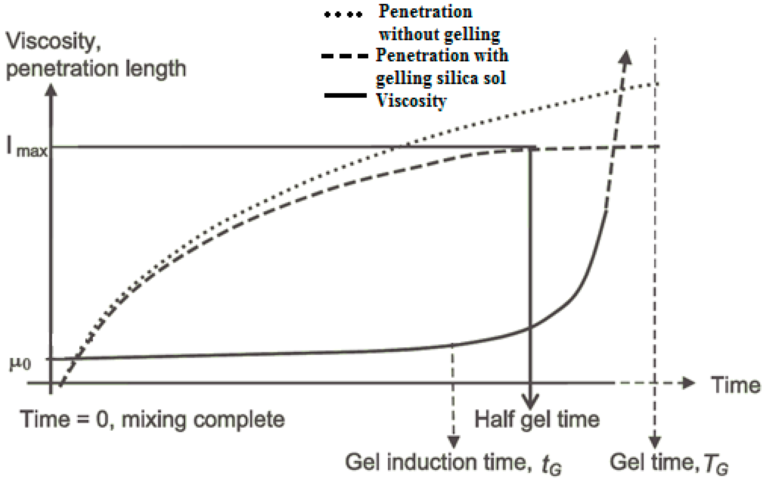
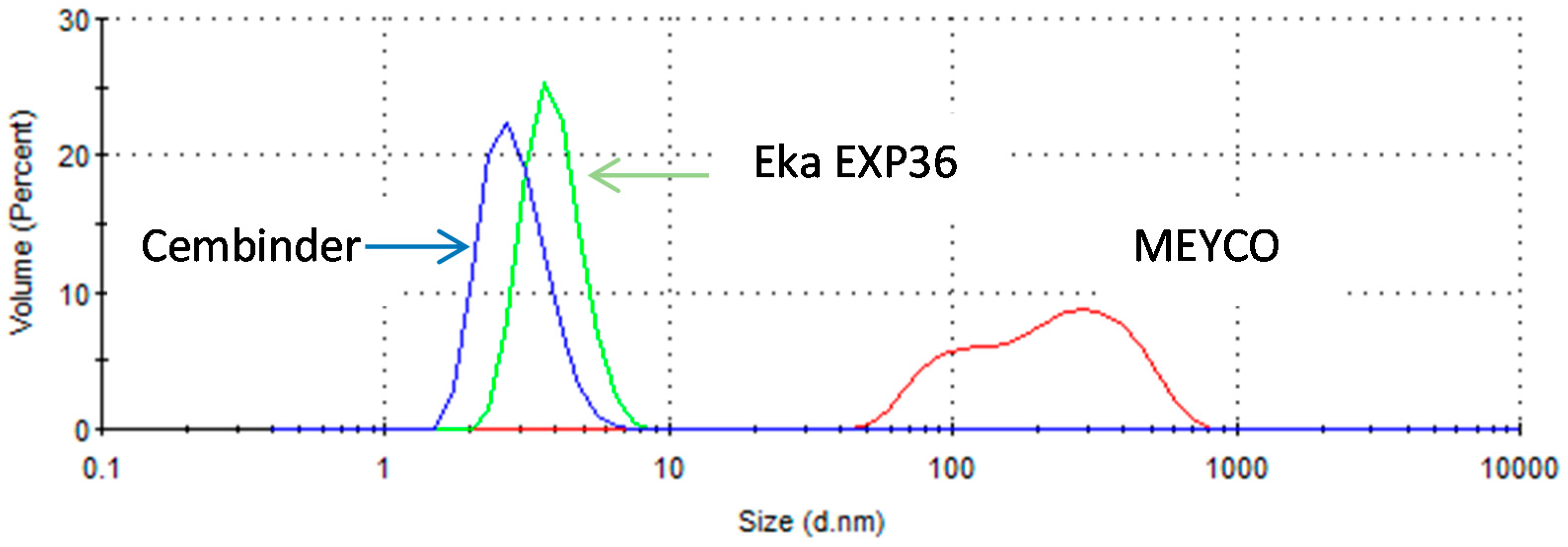
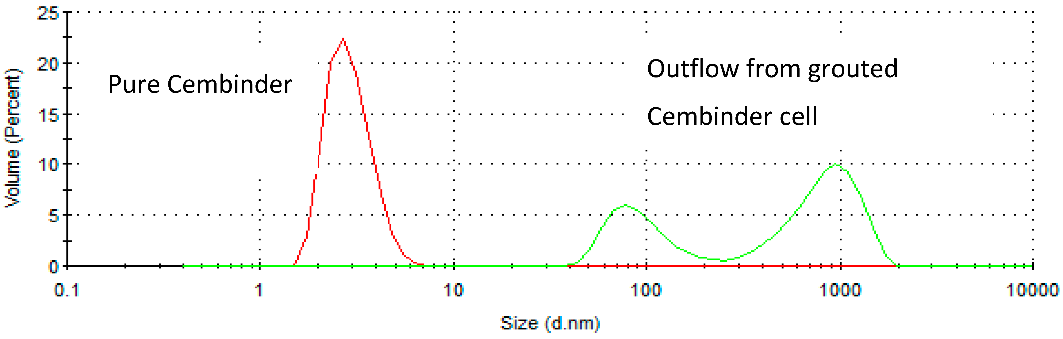
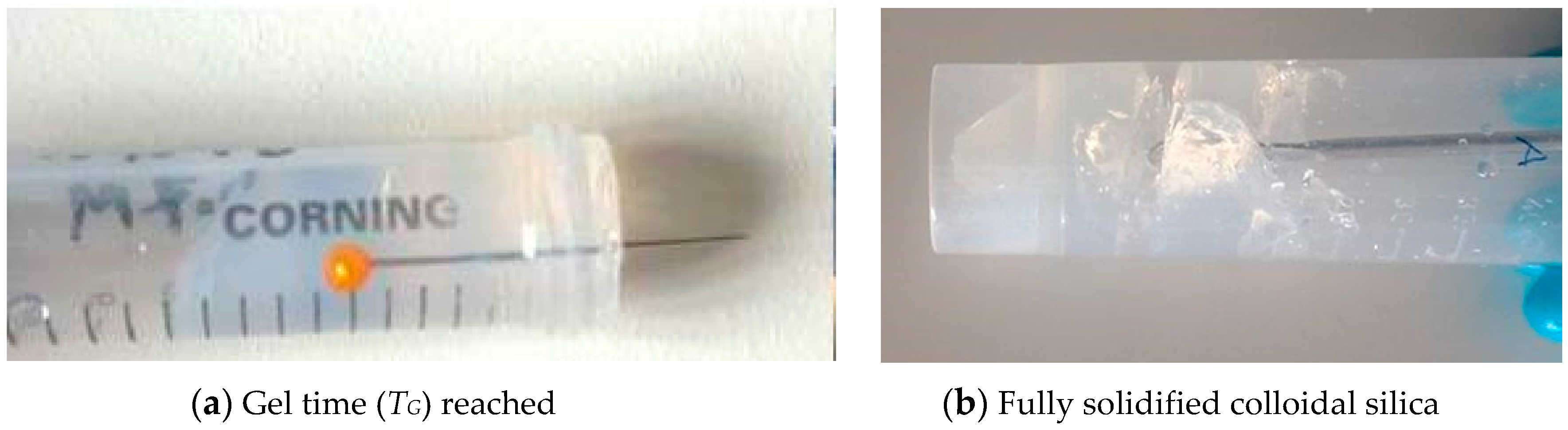
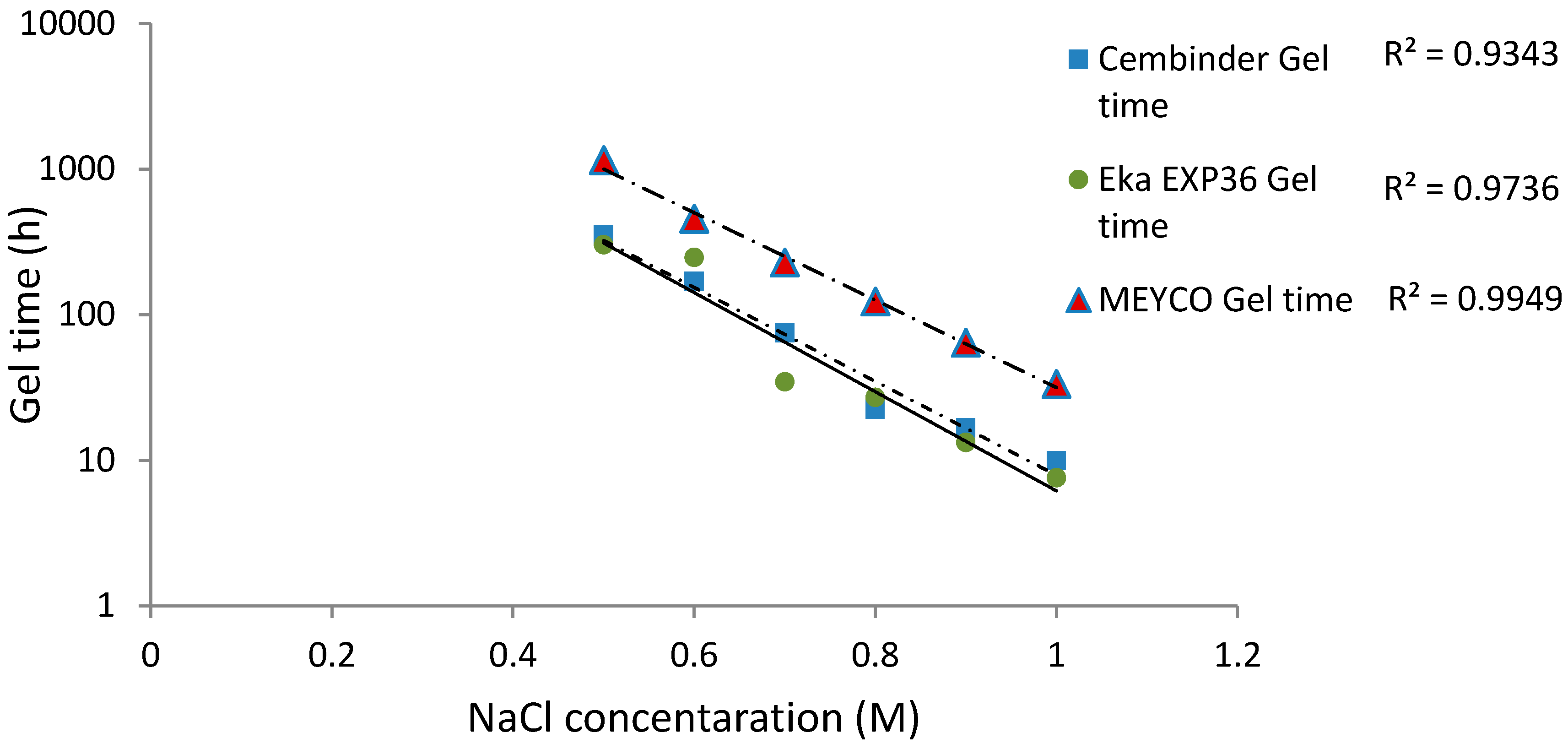
Particle size distributions were determined for the three colloidal silicas using a Zetasizer Nano ZS (Malvern Instrument®, Malvern, UK). For gel time measurement, grout samples were prepared by mixing colloidal silica with a NaCl accelerator, in a close-sealed 15 mL test tube; the gelling regime was determined based on the flowability of the gel. A needle insertion technique was used as a gelation indicator; solidified gel can show grout fracture and bond breakage on needle insertion. The gel time (TG) is defined as the point at which no grout flows when the test tube is tilted, and a needle can be supported by the grout, but its insertion does not cause grout breakage. This viscous gel phase lasts for some time, until the grout becomes completely solidified and local fractures occur upon needle insertion.
The gel induction time (tG) was determined by rheometer measurement (Anton Paar MCR 502
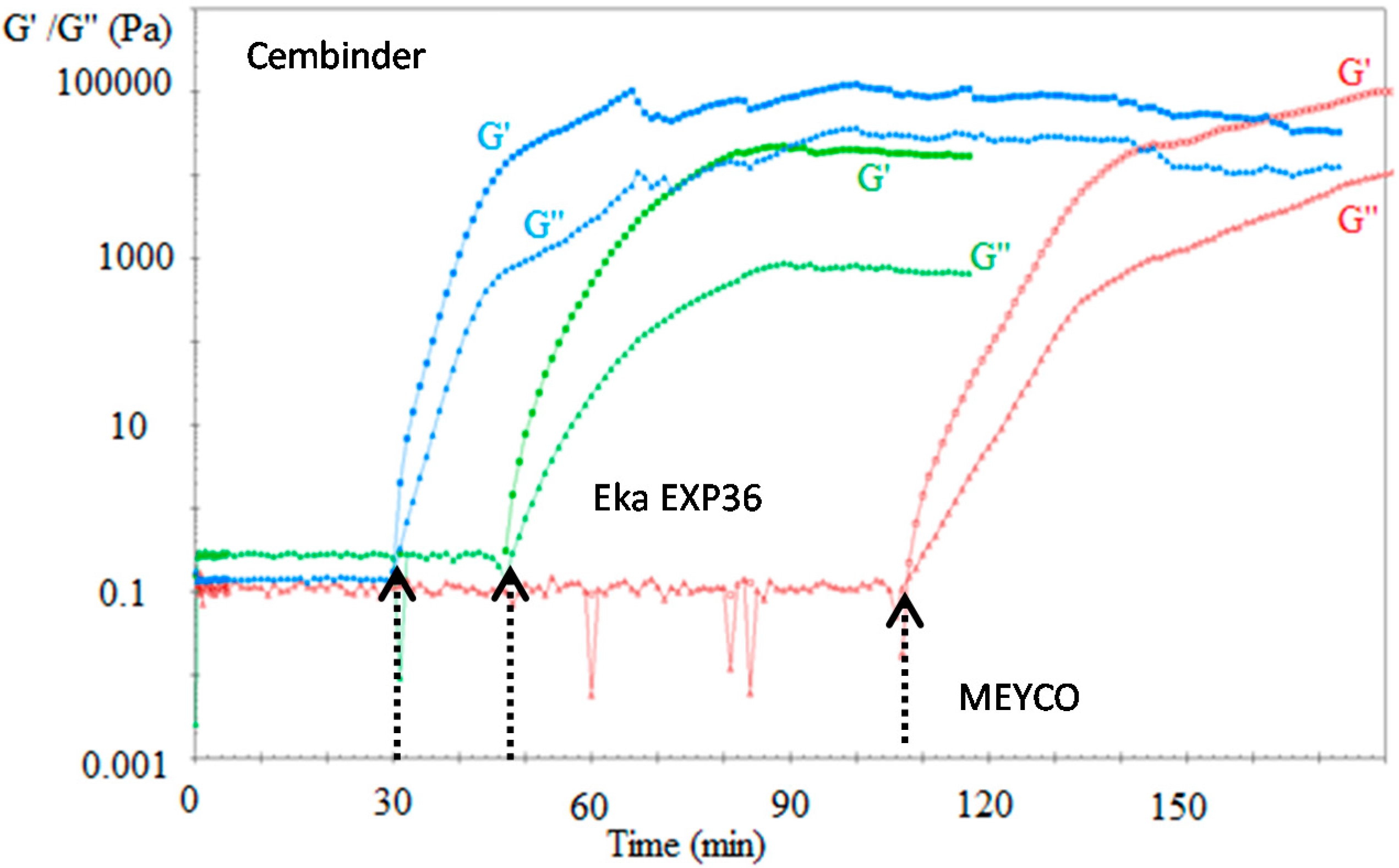
®, Graz, Austria). Colloidal silica sol was mixed with the accelerator and quickly transferred onto the rheometer measuring plate. A 2°, 20 mm diameter cone was lowered onto the colloidal silica surface. In order to determine the storage and loss moduli, oscillatory rheometry was performed at a 1% strain rate, with an oscillation frequency of 1 Hz; the temperature of the control plate was maintained at 20 °C. Storage modulus (G’) and loss modulus ( G ) were plotted as a function of time using RheoPlus© software (version 3.61, Graz, Sweden). These moduli are parameters that characterise the Hookean and Newtonian components of material behaviour [12]. As expected, the loss moduli remained relatively constant and the storage moduli were infinitesimally small within the linear viscoelastic region, but upon gelation, the storage moduli became significant and overtook the loss moduli as setting progressed, and the elastic properties became dominant. The point of intersection between the storage and the loss moduli is defined as the gel induction time (tG).
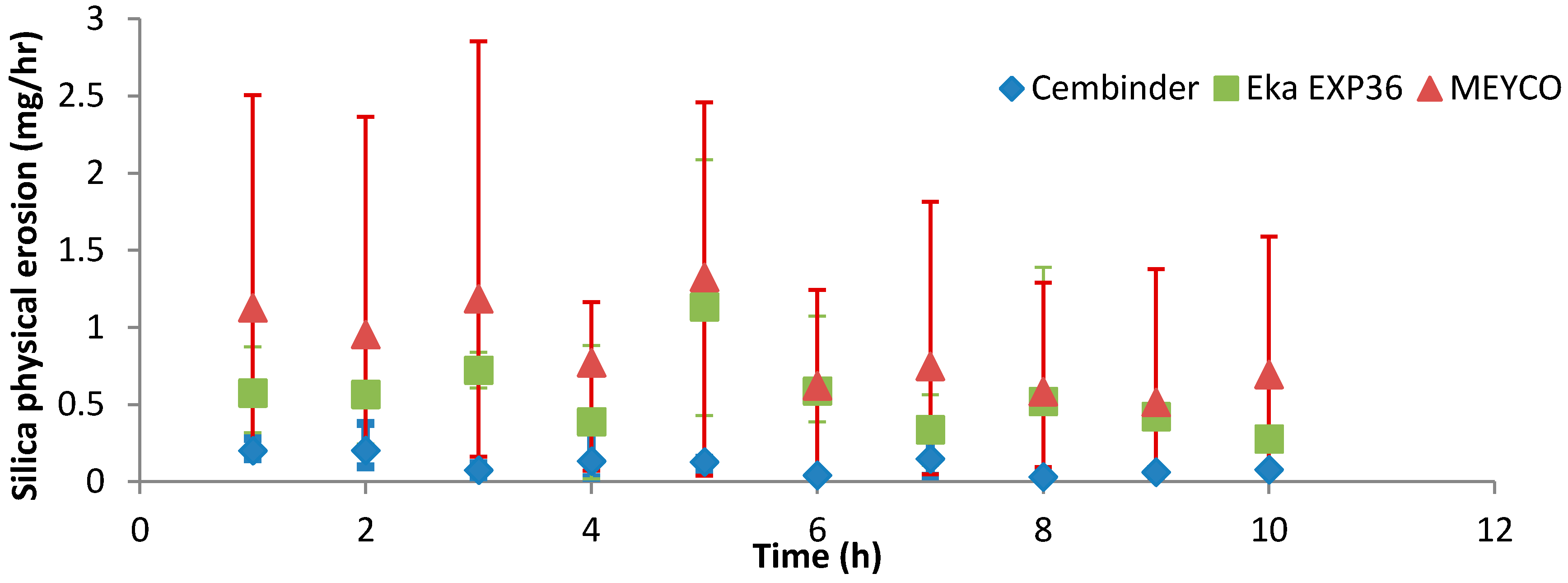
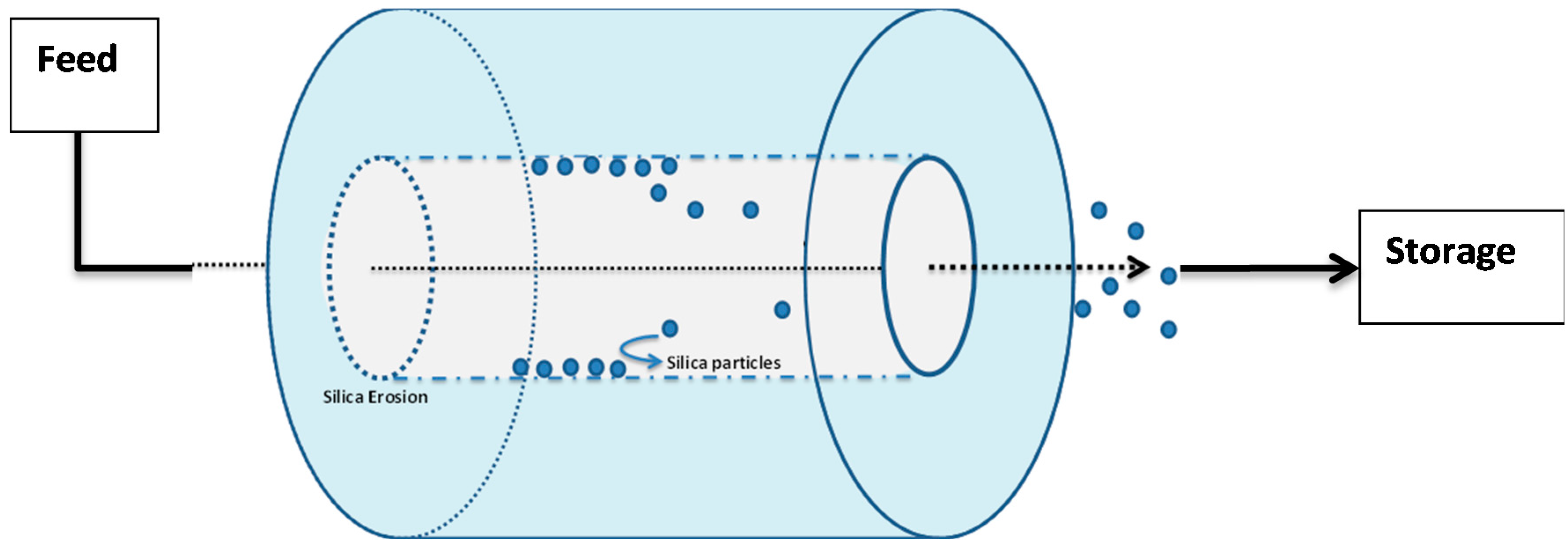
In order to measure silica erosion, a laboratory-prepared model groundwater (0.05 M NaCl in deionised water) was continuously pumped through a cylindrical hole in a grouted body, at a volumetric flowrate of 0.42 mL/min for ten hours, corresponding to a linear velocity of 2.2 × 10⁻⁵ m/s. This velocity was chosen as it is within the groundwater flow range at ONKALO [6], and it enabled a sufficient volume of the sample to be collected for turbidity analysis every hour. The cylindrical hole in the grout had an internal diameter of 0.02 m, a length of 0.10 m, and a wall thickness of 0.005 m. The effluent was sampled every hour over the 10-h period. The turbidity of the effluent was measured by a turbidimeter (HACH 2100N®, Manchester, UK), in order to assess the presence of silica particles suspension. The solution was further analysed by atomic absorption spectroscopy (Agilent Technology 240FS, Santa Clara, US), in order to convert the readings from NTU (Nephelometric Turbidity Units), to mass of silica (mg/h).

3. Results

3.1. Particle Size Distribution

From the size distribution by volume plots (see Figure 2), it was found that Cembinder, Eka EXP36, and MEYCO MP320, all demonstrate monodispersity of particle size—each showing a single peak on the size distribution plot. Volume-based size distribution shows that Cembinder has one peak at 2.9 nm, Eka EXP36 at 4.0 nm, and MEYCO MP320 at 248 nm. Overall, as can be seen from Figure 2, Cembinder has smaller particle sizes, though the results for Cembinder are very similar. The particle size range for Eka EXP 36 and Cembinder was 1.5 to 9 nm, whereas MEYCO MP320 had a broader size distribution and larger particles (40 to 800 nm). When mixed with salt accelerators, the maximum particle size of the mixtures did not exceed 10 μm at the initial mixing stage. According to penetration theories, the smallest fracture that such colloidal silica can penetrate, would typically be taken as 30 μm, which is much smaller than the targeted rock fracture for colloidal silica grouting (100 μm), demonstrating that these colloidal silicas have a suitable maximum size for grouting such fractures, though they might not be suitable below 30 μm. Figure 3 shows a comparison of the outflow silica content from a grouted Cembinder flow cell and pure Cembinder; the particle size of the outflow has two main peaks, at 123 nm and 1005 nm, both of which are much larger than the size distribution of the pure Cembinder (2.9 nm). This shows that the outflow from the grout cell includes undissolved silica from physical erosion.

3.2. Gel Time (TG)

Test tube methods were employed in order to understand the gelling mechanism and the approximate gel time relationship with accelerator concentration. It was found that, after addition of the accelerator, the grouts show a viscous phase, during which the viscosity of the grout becomes significantly higher than that of the initial silica sol; this viscous phase lasts for some time, until the grout becomes completely solidified, after which, local fractures occur upon insertion of a needle, as shown in Figure 4.
The gel times are plotted with respect to the NaCl concentration, as shown in Figure 5. It was found that the logarithm of the gel time shows a strong linear relationship with NaCl concentration (R2 > 0.93). At 20 °C, Eka EXP36 generally gelled the fastest, closely followed by Cembinder, whereas MEYCO MP320 had the longest gel time, by a factor of as much as ten. The difference in gel times is likely to be the result of the different size distributions and the differences in chemical stabilities of the three colloidal silica sols. The equations of the best log-linear fits for the colloidal silica gel time are tabulated in the conclusions section.

3.3. Gel Induction Time (tG)

Figure 6 plots the loss modulus (triangular markers) and the storage modulus (square markers). These two moduli reflect the viscous and elastic components of a fluid, respectively.
Before the gel induction stage, the loss modulus dominates the fluid properties, and the storage modulus is infinitesimally small, until a point is reached at which the storage modulus suddenly shoots up, becoming higher than the loss modulus. The point of intersection between the storage and loss modulus is defined as the gel induction time (see indicative arrows in Figure 5).
It was found that the gel induction time plot (tG) followed similar trends to the gel time plots (TG), where MEYCO MP320 required a much longer time to reach the gel induction time, when compared to Cembinder and Eka EXP36. When accelerated with 1 M NaCl (five-parts grout to one-part accelerator by volume), at 20 °C, Cembinder, Eka EXP36, and MEYCO MP320 had gel induction times of 0.5, 0.78, and 1.8 h, respectively; times which are much shorter than their respective gel times (TG) of 9.93, 7.58, and 33.45 h, respectively.
Figure 7 presents the gel induction time (tG) with respect to the concentration of NaCl, at 0.75 M, 1 M, and 1.25 M. It was found that, when the NaCl concentration exceeded 1.25 M, the storage modulus (G’) of the grout was higher than the loss modulus (G’’) from the start of testing (which was almost immediately after mixing), meaning that the elastic component became dominant from the time at which the sample was put in the rheometer, and so it was not possible to determine a gel induction time.
Strong linear relationships (R2 > 0.93) were observed between gel induction times and NaCl concentrations. Figure 5 and Figure 7 show that MEYCO MP320 has the longest gel time at each NaCl concentration, for both gel induction time (tG) and gel time (TG). This suggests that MEYCO MP320 is the most manageable grouting material in terms of gel time control, followed by Eka EXP36, whereas Cembinder shows the highest sensitivity when a NaCl accelerator is used. The difference between Eka and Cembinder is very small, as can be seen in Figure 5.
It may be noted that in tests which use calcium chloride as an accelerator, because of the divalent calcium ion, the grouts showed rapid, unmeasurably short gel times. The storage modulus of these mixes was much larger than the loss modulus from the time of testing (which was again almost immediately after mixing), demonstrating that these fluids show elastic behaviour from this time and are not useable as grouts.

3.4. Silica Erosion

The physical erosion of Cembinder, Eka EXP36, and MEYCO were studied in the flow cell; see the schematic in Figure 8. In initial trials with deionised water, it was found that all three grouts showed rapid breakdown. When subjected to a flow of 0.05 M NaCl solution at a superficial velocity of 2.2 × 10⁻⁵ m/s, there was physical erosion (loss of solid material) from all three colloidal silicas. This loss occurred steadily throughout the 10 h test period. The physical erosion was assessed by a turbidimeter as a measure of the silica particles in suspension (unit: NTU). The total silica concentration was measured by atomic absorption spectroscopy.
Figure 9 shows that, overall, MEYCO had the highest erosion rate (0.85 mg/h) and the greatest variability in the results; Cembinder showed the lowest erosion rate, of 0.11 mg/h. All experiments were run three times and Cembinder had the lowest variability of results, as well as the lowest erosion rate with 0.05 M NaCl solution. The chosen flow-rate is within the range of naturally occurring groundwater velocity, and the experiment suggests that Cembinder grout is the least likely to be removed under saline groundwater conditions in the geodisposal scenario, although further investigation is clearly required, and this work is in progress.

4. Discussion

Cembinder, Eka EXP36, and MEYCO MP320 all show monodispersity of silica particle size, with Cembinder and Eka EXP36 particle sizes ranging from 1.5 to 9 nm, whereas MEYCO showed a broader and coarser size range, from 40 to 800 nm. The difference in peaks may be influenced by the pH of the environment, and the manufacturing process used, which would ultimately impact the chemical stability, agglomeration. and colloidal size distribution. The particle sizes do not exceed 10,000 nm (10 μm), even when the grouts are mixed with the NaCl accelerator. It is therefore concluded that all three colloidal silicas are potential candidate grouting materials, that can achieve a sealing of fractures <100 μm, though perhaps not for fractures <30 μm.
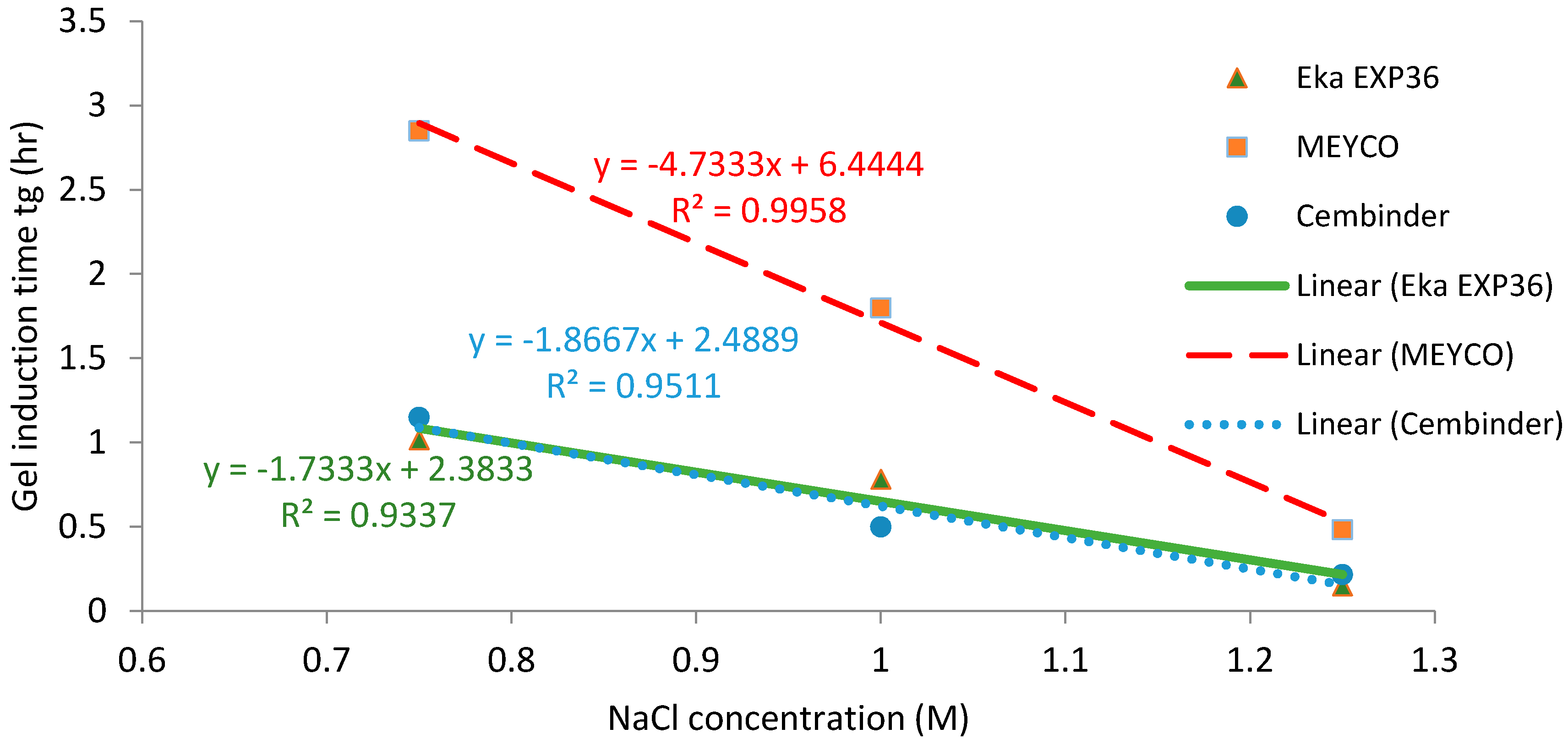
The gel induction time was measured by oscillatory shear rheometry, whereby small changes of viscoelastic properties could be registered every minute (error range ± 0.5 min). In contrast, the tilted test tube method, although very simple and amenable to use on site, measured the gel time (TG) according to completion of grout solidification, on an hourly basis. The latter measurement technique is more basic, and has a variable error range, from ±2 min to several hours.
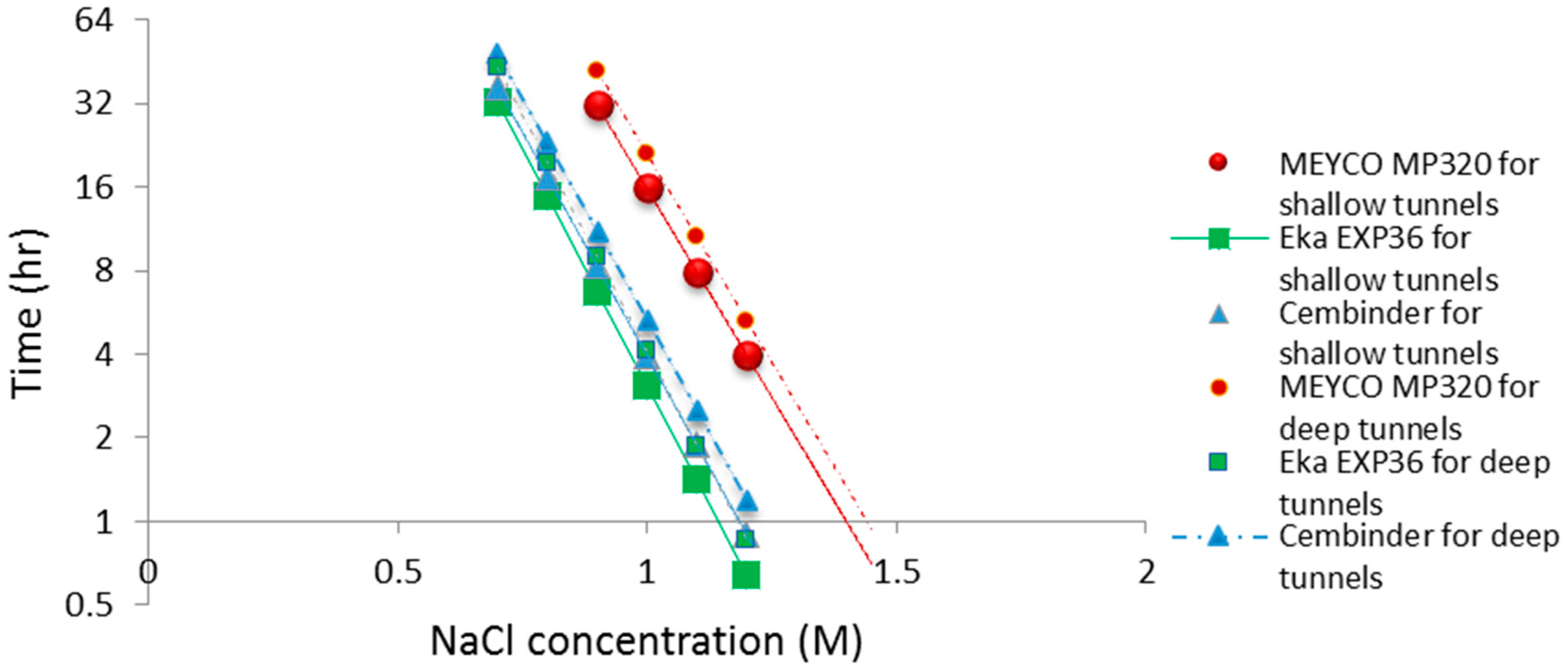
The operational time is the time which allows the grout to be prepared and pumped into the borehole, before gelation takes place. Funehag [5] advises that the grout operational time for shallow tunnels (<100 m) should be half of the gel time, whereas for deep tunnels (>150 m), it should be at least two thirds of the gel time. Based on this and the gel time results, it is possible to plot operational times for deep and shallow tunnel grouting; see the dashed and solid lines in Figure 10. The fitted linear regression equations for the gel induction time (tG), gel time (TG), and operational time, for shallow and deep tunnels, are tabulated in Table 1 below.
From the calculated regression equation, it can be concluded that MEYCO was the least sensitive to the accelerator addition, and thus, its set time would be the easiest to manage during the grouting processes.
All three colloidal silica samples showed a strong log-linear relationship between the gel time (TG) and the NaCl concentration, as well as a strong linear relationship between the gel induction time (tG) and the NaCl concentration. MEYCO MP320 showed the lowest sensitivity to NaCl concentration, which suggests that it is the most manageable grout in terms of gel time control, with Eka EXP320 the next most easily managed, and then Cembinder. Furthermore, it is worth noting that the gel induction time (tG) shows a broadly linear trend with the accelerator, whereas the gel time (TG) shows a log-linear trend; this suggests that there could be different dominant processes during these two stages of setting.
Resistance to physical erosion is an important criterion for grout approval. Although it has perhaps the best gel time control behaviour, MEYCO showed the highest physical erosion rate in the initial tests reported here. Cembinder performed relatively well in terms of silica erosion resistance, although it had a shorter gel time for grouting operations. The erosion experiments were performed with 0.05 M NaCl solution at a superficial velocity of 2.2 × 10⁻⁵ m/s, and the results suggest that the greater part of the silica removal was by physical erosion. However, this statement should be further verified at various conditions, in order to cover a variety of groundwater concentrations (0.03 M to 1 M NaCl) and flow rates (0.004–16.6 mL/min) in the geodisposal environment, noting that all three grouts showed rapid breakdown when challenged with deionised water. This recommendation is further supported by the crude theoretical analysis below.
We may use these erosion rates to make a crude estimate of the potential for grout fracture dilation under repository conditions.
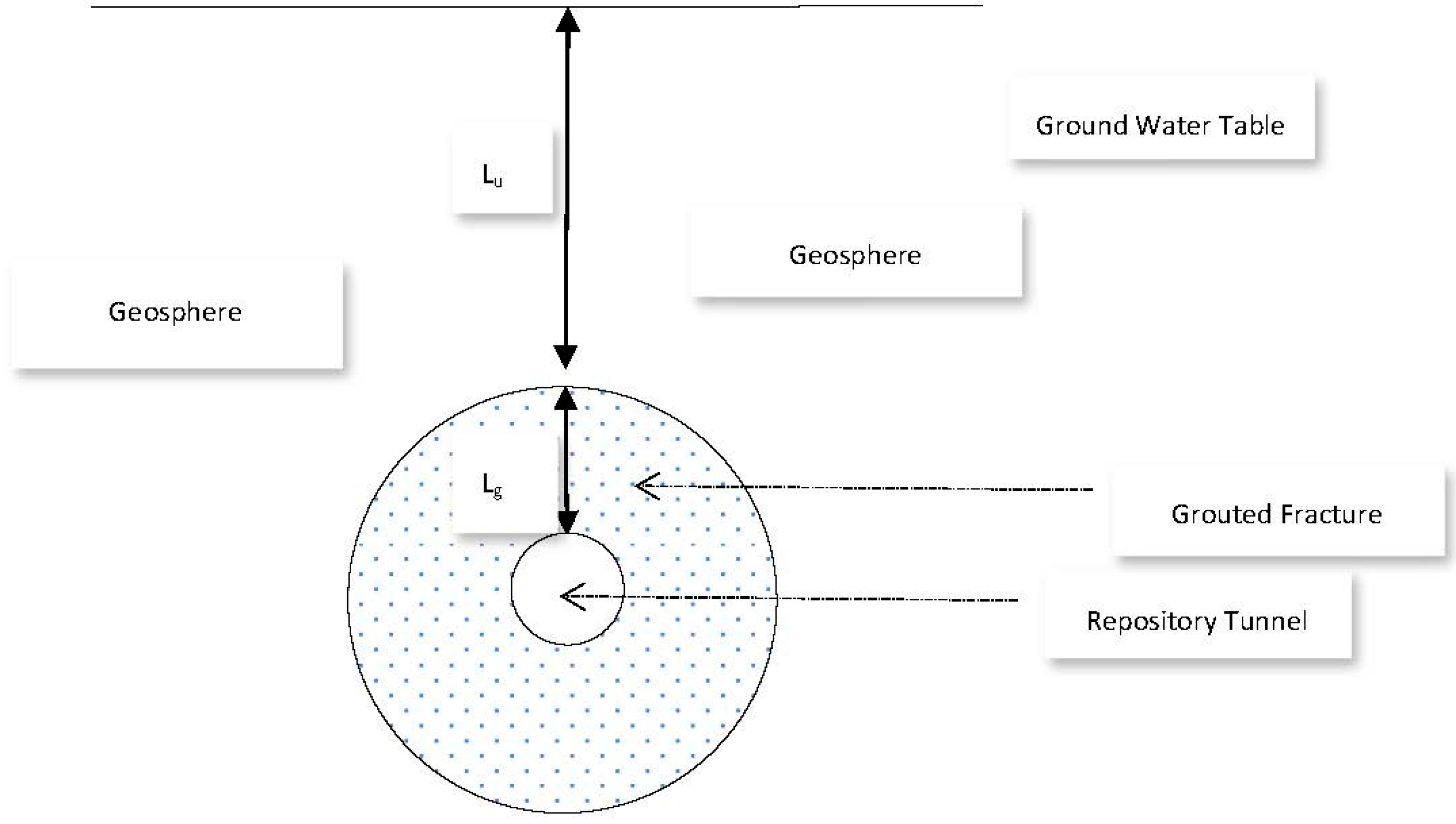
Let us assume the sealed repository tunnel to be horizontal, cylindrical, and filled with air at atmospheric pressure (Figure 11).
In order to ensure that any fractures in the surrounding rock are hydraulically sealed, we assume that an annular grouted zone surrounds the tunnel and lies between a tunnel diameter of 1.5 m, and the surrounding geosphere, at a diameter 12 m. If the vertical depth of the uppermost part of the grouted zone below the water table is Lu, and the annular width of the grouted zone is Lg, then the hydraulic pressure just above the grouted zone is ρ w g Lu. Here, ρ w is the density of groundwater and g is the acceleration due to gravity. The vertical hydraulic pressure gradient across the grouted zone is then:
Δ p L g = ρ w g L u L g
Similarly, at a point level with the tunnel axis, and if we neglect the small tunnel radius, then the horizontal hydraulic pressure gradient across the grouted zone is:
Δ p L g = ρ w g ( L u + L g L g )
However, since Lu/Lg > 1, the result in Equation (4) is essentially the same is that in Equation (3).
Furthermore, we will assume that a fault has developed within the placed grout, due to an imperfect grouting procedure, seismic events, or other reason. This leads to the development within a grouted fracture of a rectangular open slot of width W and fracture thickness 2 d (both perpendicular to the fracture length) and of length Lf (parallel to the fracture length), and subject to a pressure drop over its length of ΔP. We also assume that flow within the slot is a laminar Poiseuille flow, for which the flow-rate is given by the Hagen-Poiseuille law (Bird, Stewart, & Lightfoot, 2007):
Q = 2 3 Δ p L f d 3 w μ
where Q is flowrate, ΔP/Lf is the hydraulic pressure gradient along the grouted fracture slot, and μ is viscosity. We will consider two scenarios; (a) an isolated slot in the grouted fracture, in which the fluid velocity corresponds to, and is parallel to, the natural movement of ground water, and (b) a longer, more extensive slot, adjoining and parallel to the whole of the fracture length, and where hydraulic communication occurs between the geosphere and the tunnel (because the fracture itself spans this distance). In this latter case, LfLg (the fracture may take a somewhat tortuous path). We further take 2 d to be one micron, W to be in the order of 1 metre, Lu to be in the order of 500 m, and set Lg = (12 − 1.5)/2 m = 5.25 m, in which case the hydraulic gradient across the fracture ( L u + L g L g ) is 96.
We assume a very basic worst-case erosion scenario; our erosion results are measured under conditions of saturation equilibrium between grout and flowing groundwater, so that scaling of the erosion rate is proportional to the volumetric flow-rate and the saturation concentration. Our results indicate that, for a flowrate of 0.42 × 10⁻⁶ m3/min or 7 × 10⁻⁹ m3/s, and a linear velocity of 2.2 × 10⁻⁵ m/s, the physical erosion rate (measured via turbidity measurements) is in the order of 1 mg/h. The removal of amorphous silica by solution might be at a similar rate; the equilibrium saturation of amorphous silica is about 100 to 120 mg/L (0.01% to 0.012%) at room temperature, and with a flow rate of 0.42 mL/min or 25 mL/h, the amorphous silica removed by solution per hour is then: (25/1000) L/h × 100 mg/L = 2.5 mg/h. However, the chemical dissolution was not measured independently. In any event, the chemical dissolution rate estimated here is of a similar order of magnitude to that for the physical erosion, and we will assume a total value for the rate of erosion in the order of 1 mg/h.
For scenario (a), there is no hydraulic communication between the geosphere and the tunnel; the pressure gradient applicable in Equation (5) is not known. Instead, we proceed as follows. Under conditions of naturally quiescent ground water flow, the residence times for groundwater are in the order of 1000 s of years, to move across distances of perhaps 100 s of metres, corresponding to velocities in the order of 1 × 10⁻⁹ m/s, and thus flow-rates through our fracture slot are in the order of 1 × 10⁻¹⁵ m3/s. This figure is perhaps 107 times smaller than that of the experimental study. In this case, the total erosion rate is also reduced by the same factor. Assuming a repository lifetime of 100,000 years, this corresponds to a total grout erosive loss of roughly one tenth of a gram. Assuming that the grout has a density in the order of 1000 kg/m3, our plane parallel grouted fracture slot, of width one micron and area extent of 5 m2, would increase in width by two percent. This is negligibly small.
However, under a failure scenario in which the fracture slot penetration is complete, and is such as to allow hydraulic communication between the geosphere and repository tunnel, the resulting hydraulic pressure gradient along the slot at repository depths is likely to reach that given in Equation (3). With viscosities for water in the order of 10−3 Pa·s, we may apply Equations (3) and (5) with Lf = Lg, to predict much higher flow-rates in the order of 10−10 m3/s. This is now one percent of the experimental flow rate. In this case, the total erosive grout loss over the repository lifetime will lead to a fracture dilation which is 105 greater, i.e., in the order of millimeters, which represents a much more serious scenario and, for example, all grout could be removed from a 100 micron grouted fissure within 5000 years.
In these calculations, we have made a number of severe assumptions which mean that the results are only reliable within an order of magnitude. For instance, we have assumed that equilibrium saturation conditions between grout and flowing groundwater, would also apply at the higher flowrates. In fact, the fluid in the fracture would tend to become undersaturated; under a constant concentration driving force, the total rate of erosion would be proportional to the mass transfer coefficient. The latter is known to be a much weaker function of linear velocity and hence flowrate; boundary layer theory suggests this to be a square root relationship. Note that this observation relates to erosion as a result of grout dissolution. The erosion estimate is therefore likely to be an exaggerated one. Furthermore, the groundwater which flows into the tunnel will eventually flood the whole repository, and this will tend to nullify the hydrostatic pressure gradient. On the other hand, physical erosion will not be limited to saturation issues and there is potential for grout masses to become detached from the fissure walls. In addition, as the grout fracture widens, both the flowrate and erosion rate will increase correspondingly. In balance, we can reasonably expect the total rate of grout erosion to be of a magnitude higher than that occurring in the case of naturally quiescent flow.
The above analysis has been performed based on an extrapolation of the experimental tests, made under the salinity and pH conditions selected. It suggests that further investigation of the erosion under different conditions is warranted. Erosion rates in which groundwater salinity differs significantly from the grout preparation salinity, are expected to be higher.

5. Conclusions

Amongst the colloidal silica selection criteria published by the Chalmers University of Technology, is a recommendation that the gel time should be controlled, so that it lies between 15 and 50 min [5]. This time is taken to be sufficient for allowing the mixing, pressurising hoses, and actual grouting, without excess grout consumption. For grouts with long gel times injected into fissures with flowing groundwater, grout injection must be continued until the grout is gelling, to prevent it from being washed out. Thus, grouts with long gel times require long grouting times [5], and so can involve high grout injection volumes. With this limitation, it follows that the operational time for deep tunnel grouting should be restricted to 10 to 33 min (i.e., two thirds of the gel time [5]. Therefore, for the grouts considered in the present study, the appropriate concentration range of the NaCl accelerator should be 1.5–1.7 M for MEYCO, 1.23–1.38 M for Eka EXP36, and 1.3–1.47 M for Cembinder, in order to achieve the desired operational time range. These times have been calculated by substituting the desired gel time range (15 to 50 min) into the gel time regression equations of Table 2. The overall NaCl accelerator and colloidal silica mixing guidelines for deep tunnel grouting, are tabulated in Table 2.
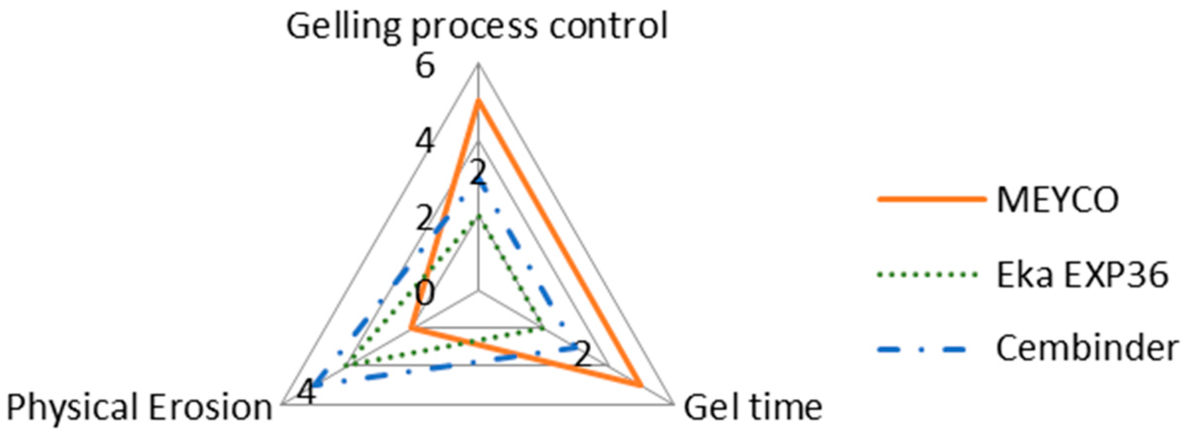
The intention of this research is not to make final recommendations about which of the three grout materials tested is the best, but rather to provide comparative observations regarding different behaviours of the three grouts. It is important to note that whilst one of the colloidal silica may score high on certain aspects, it may score less well on others, as shown in the radar chart in Figure 12.
According to Figure 12, MEYCO offers the greatest gelling process control and the longest gel time, when compared to the other two colloidal silica grouts. A longer gel time means that the grout can achieve longer penetration lengths, which also means that the grout can seal fractures to greater depths within the rock structures, but that grouting may have to be continued for longer, in order to avoid washout when the grout pressure is released. However, MEYCO showed the highest physical erosion out of the three grouting materials, whereas grouting with Cembinder results in the least erosion, with the values for Eka EXP36 lying in between. This suggests that in a natural environment where grout is in contact with groundwater, Cembinder and Eka EXP36 are more stable than MEYCO, in terms of silica erosion. The radar chart in Figure 12 provides a product overview in terms of the area of enclosure. Each of the three parameters scores a higher mark as the scale expands outward; hence, the larger the overall area, the better the overall grouting performance of each product. It is important to understand that the erosion experiments provide a performance comparison among the three grouts, though it does not necessarily reflect the full geodisposal scenario, where the groundwater velocity and other behaviours could vary.
Calculations which extrapolate the measured rate of physical erosion of the grout suggest that fracture dilation is unlikely to be significant under naturally quiescent groundwater flow. However, under conditions in which imperfect grouting, fracture movement, or some other opening mechanism allows hydraulic communication between geosphere and repository, the dilation is much more significant.
The impact of various geodisposal conditions on grout erosion will thus be part of further research.

Acknowledgments

This research project is funded by the Engineering and Physical Sciences Research Council (EPSRC) and the NDA RWMD (Nuclear Decommissioning Authority Radioactive Waste Management Directorate), now RWM (Radioacitve Waste Management Limited), with the grant title ‘SAFE Barriers—a Systems Approach For Engineered Barriers’ and the grant reference EP/I036427/1.The authors would like to thank the research team from the University of Strathclyde for their support and advice, as well as AkzoNobel for providing colloidal silica samples free of charge.

Author Contributions

Pingqian Shen conceived, designed and performed the experiments, carried out an analysis of the data and drafted the paper under the supervision of Nicholas Hankins and Stephan Jefferis who both furthered the analyses and developed the theoretical analysis of grout erosion in a repository setting; Akzonobel contributed grouting materials and the University of Strathclyde granted us use of their Zetasizer Nano ZS instruments.

Conflicts of Interest

The authors declare no conflict of interest.

References

  1. Hicks, T.; White, M.; Hooker, P. Role of Bentonite in Determination of Thermal Limits on Geological Disposal Facility Design; Galson Sciences Limited: Oakham, UK, 2009. [Google Scholar]
  2. Butron, C.F. Drip sealing of tunnels in hard rock: A new concept for the design and evaluation of permeation grouting. Tunn. Undergr. Space Technol. 2010, 25, 114–121. [Google Scholar] [CrossRef]
  3. Chapman, N.; Bath, A.; Geier, J.; Stephansson, O. The Disposal Site and Underground Construction: Part II: Preserving the Favourable Properties of the Bedrock during Construction; Säteilyturvakeskus: Leuven, Belgium, 2015. [Google Scholar]
  4. Alexander, G.; Heston, W.; Iler, R. The solubility of amorphous silica in water. J. Phys. Chem. 1953, 58, 453–455. [Google Scholar] [CrossRef]
  5. Funehag, J. Guide to Grouting with Silica Sol—For Sealing in Hard Rock; BeFo Report: Stockholm, Sweden, 2012. [Google Scholar]
  6. Gustafson, E.N. Forsmark Site Investigation: Groundwater Flow Measurements and SWIW Test in Borehole KFM04A; SKB: Stockholm, Sweden, 2006. [Google Scholar]
  7. Posiva Oy. Site Engineering Report; Posiva Oy: Eurajoki, Finland, 2013. [Google Scholar]
  8. Funehag, J. Sealing of narrow fractures in hard rock—A case study in Hallandsäs. Tunn. Undergr. Space Technol. 2004, 19, 1–8. [Google Scholar]
  9. Boden, A.; Sievänen, U. Low-pH Injection Grout for Deep Repositories; SKB, Swedish Nuclear Fuel and Waste management Company: Stockholm, Sweden, 2005. [Google Scholar]
  10. Holmboe, M. Effect of the Injection Grout Silica Sol on Bentonite. Phys. Chem. Earth 2011, 36, 1580–1589. [Google Scholar] [CrossRef]
  11. Butron, C.A. Silica sol for rock grouting: Laboratory testing of strength, fracture behaviour and hydraulic conductivity. Tunn. Undergr. Space Technol. 2009, 24, 603–607. [Google Scholar] [CrossRef]
  12. Ambrosio, L.; Borzacchiello, A.; Netti, P.A.; Nicolais, L. Rheological study on hyaluronic acid and its derivative solutions. J. Macromol. Sci. 1999, 36, 7–8. [Google Scholar] [CrossRef]
Figure 1. Diagram showing grout gelling parameters from [5].
Geosciences 07 00006 g001
Figure 2. The size distribution by volume of three different brands of colloidal silica.
Geosciences 07 00006 g002
Figure 3. The size distribution by volume of pure Cembinder and the outflow solution from a grouted Cembinder cell.
Geosciences 07 00006 g003
Figure 4. The grout behaviour before and after the gel time has been reached.
Geosciences 07 00006 g004
Figure 5. The gel time (TG) of colloidal silica versus molar NaCl concentration at 20 °C, with least square semi-logarithmic linear fit.
Geosciences 07 00006 g005
Figure 6. The storage (G’) and loss moduli (G’’) of three colloidal silica sols when mixed with 1 M NaCl accelerator.
Geosciences 07 00006 g006
Figure 7. Gel induction time plots (tg) of three colloidal silica samples at different NaCl concentrations.
Geosciences 07 00006 g007
Figure 8. Test flow cell for silica erosion measurement.
Geosciences 07 00006 g008
Figure 9. Physical erosion of the three grout types.
Geosciences 07 00006 g009
Figure 10. Operational time for grouting guidance in both shallow tunnels and deep tunnels.
Geosciences 07 00006 g010
Figure 11. Repository Tunnel and Grouted Fracture Zone.
Geosciences 07 00006 g011
Figure 12. A property comparison radar chart of the three colloidal silica grouts.
Geosciences 07 00006 g012
Table 1. The calculated gelling time equations for three colloidal silica samples and NaCl (5:1 volumetric ratio) at 20 °C, where y denotes time and x denotes the NaCl concentration.
Grout TypeMEYCO MP320Eka EXP36Cembinder
Gel induction time (tG)y = −4.733x + 6.44y = −1.733x + 2.383y = −1.867x + 2.49
Gel time (TG)y = 31,742 exp−6.912xy = 15,648 exp−7.84xy = 13,214 exp −7.422x
Operational time (shallow tunnels)y = 15,871 exp−6.912xy = 7824 exp−7.7845xy = 6607 exp −7.422x
Operational time (deep tunnels)y = 21,161 exp −6.912xy = 10,432 exp −7.984xy = 8809.3 exp −7.422x
Table 2. The colloidal silica sample selection guideline for deep tunnel grouting.
Tunnel Depth>100 m
Maximum Particle size10 μm
Gel Time15–50 min
Operational time10–33 min
Colloidal silica: NaCl volumetric ratio5:1
Required NaCl concentration for MEYCO MP3201.5–1.7 M at 20 °C
Required NaCl concentration for Eka EXP361.23–1.38 M at 20 °C
Required NaCl concentration for Cembinder1.3–1.47 M at 20 °C

