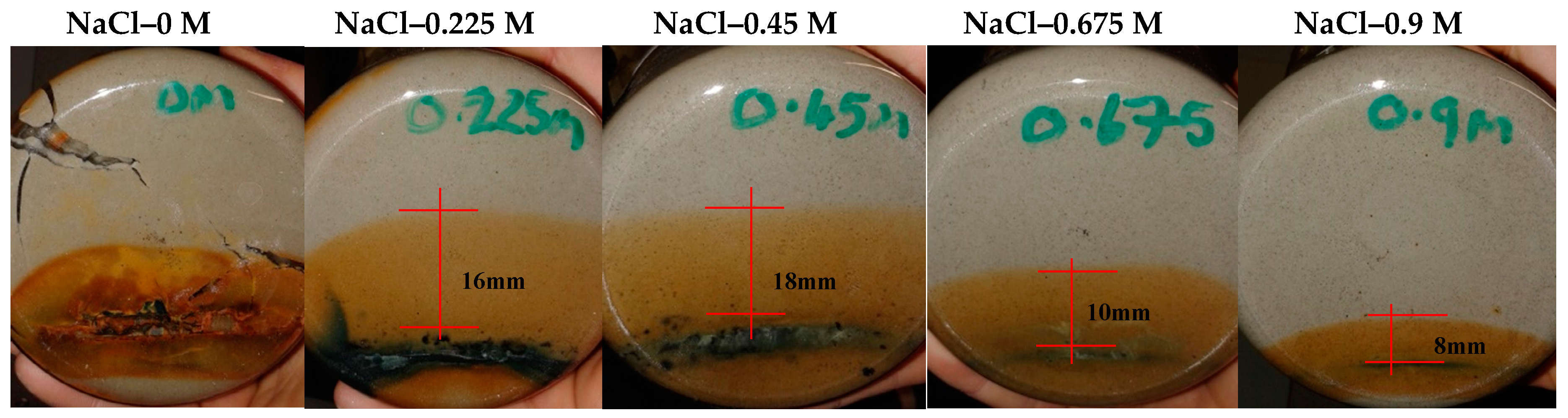
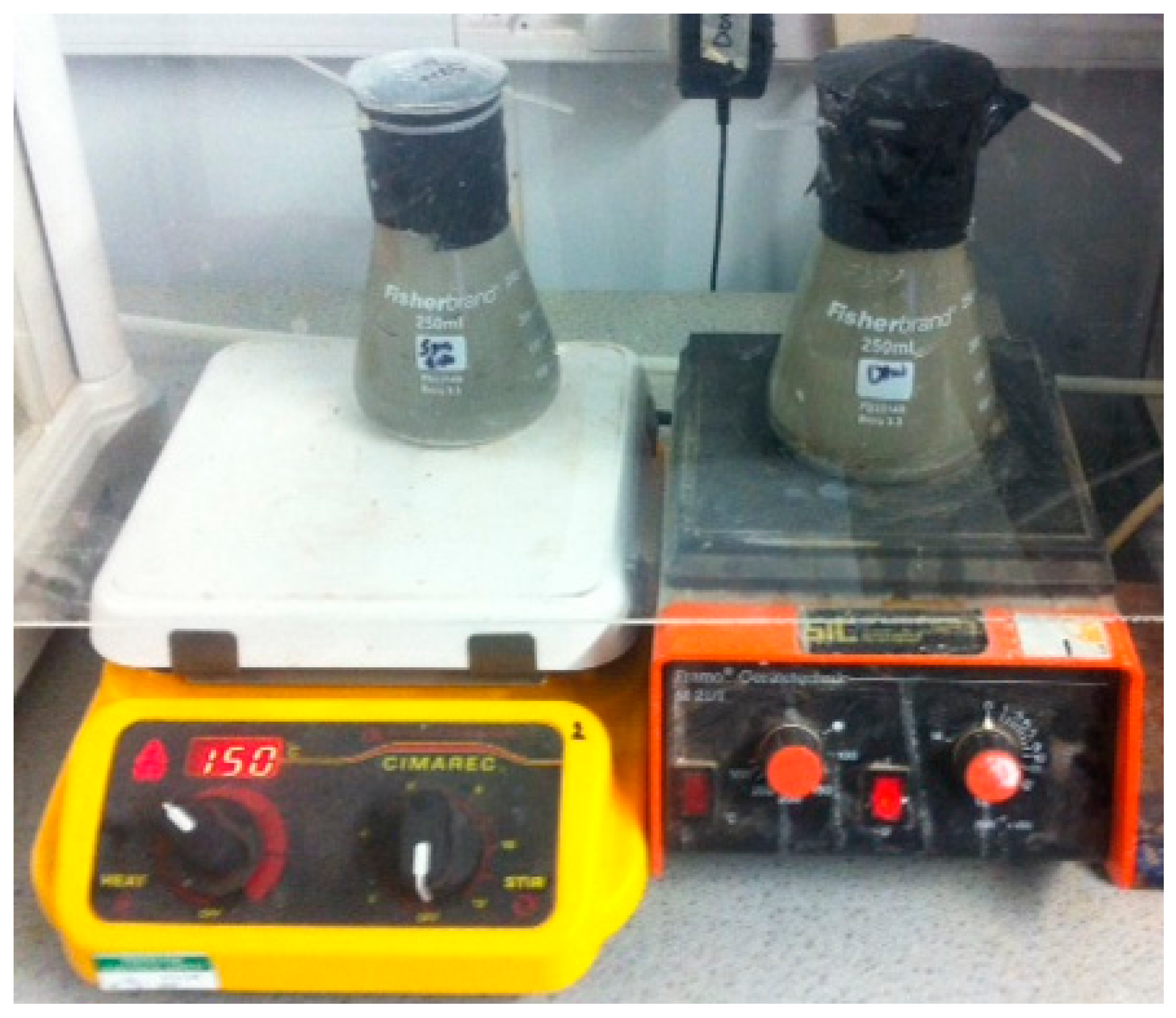
Figure 1.
Heated thermo-saline-corrosion exposure samples.
Figure 1.
Heated thermo-saline-corrosion exposure samples.
Figure 2.
From Batch test #4 (For 1 month duration, sample containing Steel/Mx-80 & distilled water), compacted and heated to 100 °C within a sealed constant volume cell (Ø: 50 mm, h: 20 mm).
Figure 2.
From Batch test #4 (For 1 month duration, sample containing Steel/Mx-80 & distilled water), compacted and heated to 100 °C within a sealed constant volume cell (Ø: 50 mm, h: 20 mm).
Figure 3.
Control swell index results, along with a comparison to a Ca-type bentonite.
Figure 3.
Control swell index results, along with a comparison to a Ca-type bentonite.
Figure 4.
Bulk XRD run on the RS® MX80 (S: Smectite, Lc: Lo-cristobalite, Z: Zeolite, Q: Quartz, PF: Plagioclase feldspar, C: Calcite).
Figure 4.
Bulk XRD run on the RS® MX80 (S: Smectite, Lc: Lo-cristobalite, Z: Zeolite, Q: Quartz, PF: Plagioclase feldspar, C: Calcite).
Figure 5.
Oriented air-dried, glycolated heat-treated XRD on the MX80.
Figure 5.
Oriented air-dried, glycolated heat-treated XRD on the MX80.
Figure 6.
002/003 intensity ratios for the RS® control.
Figure 6.
002/003 intensity ratios for the RS® control.
Figure 7.
Swell index results for batch 1 tests (Ca-bentonite results after 19), dotted line highlighting the reference salinity concentration.
Figure 7.
Swell index results for batch 1 tests (Ca-bentonite results after 19), dotted line highlighting the reference salinity concentration.
Figure 8.
PI vs. Saline solution concentration batch 1 tests (Dotted line indicates reference salinity).
Figure 8.
PI vs. Saline solution concentration batch 1 tests (Dotted line indicates reference salinity).
Figure 9.
Swell index results for batch #2 (dotted line indicates the control free swell value).
Figure 9.
Swell index results for batch #2 (dotted line indicates the control free swell value).
Figure 10.
Extent of corrosion integration under ambient conditions after 1-month exposure.
Figure 10.
Extent of corrosion integration under ambient conditions after 1-month exposure.
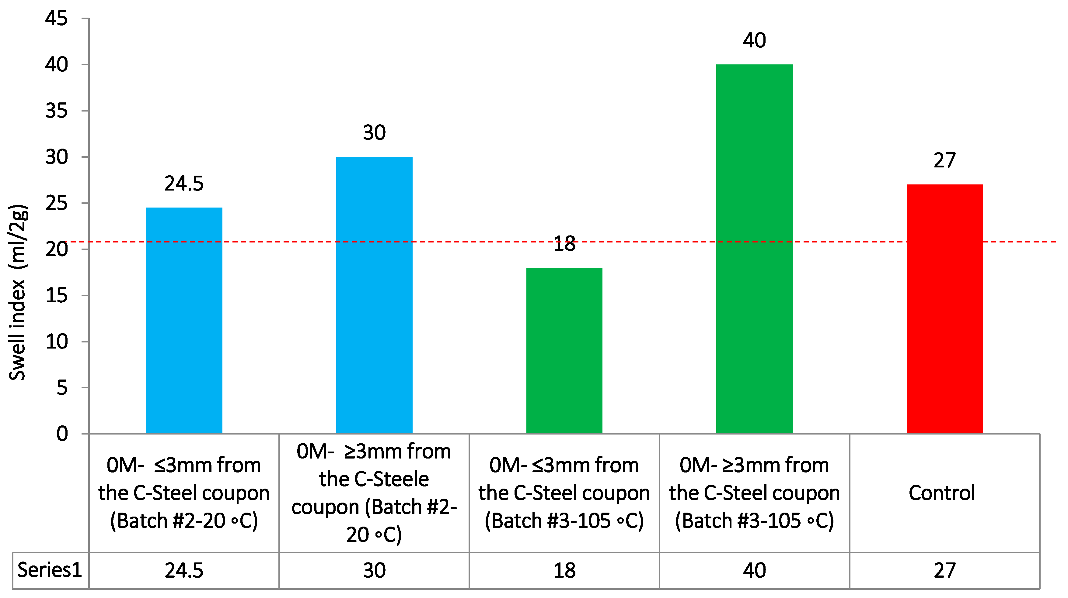
Figure 11.
Swell index results for batch #3 with a comparison to batch #2 0 M measurements at 20 °C.
Figure 11.
Swell index results for batch #3 with a comparison to batch #2 0 M measurements at 20 °C.
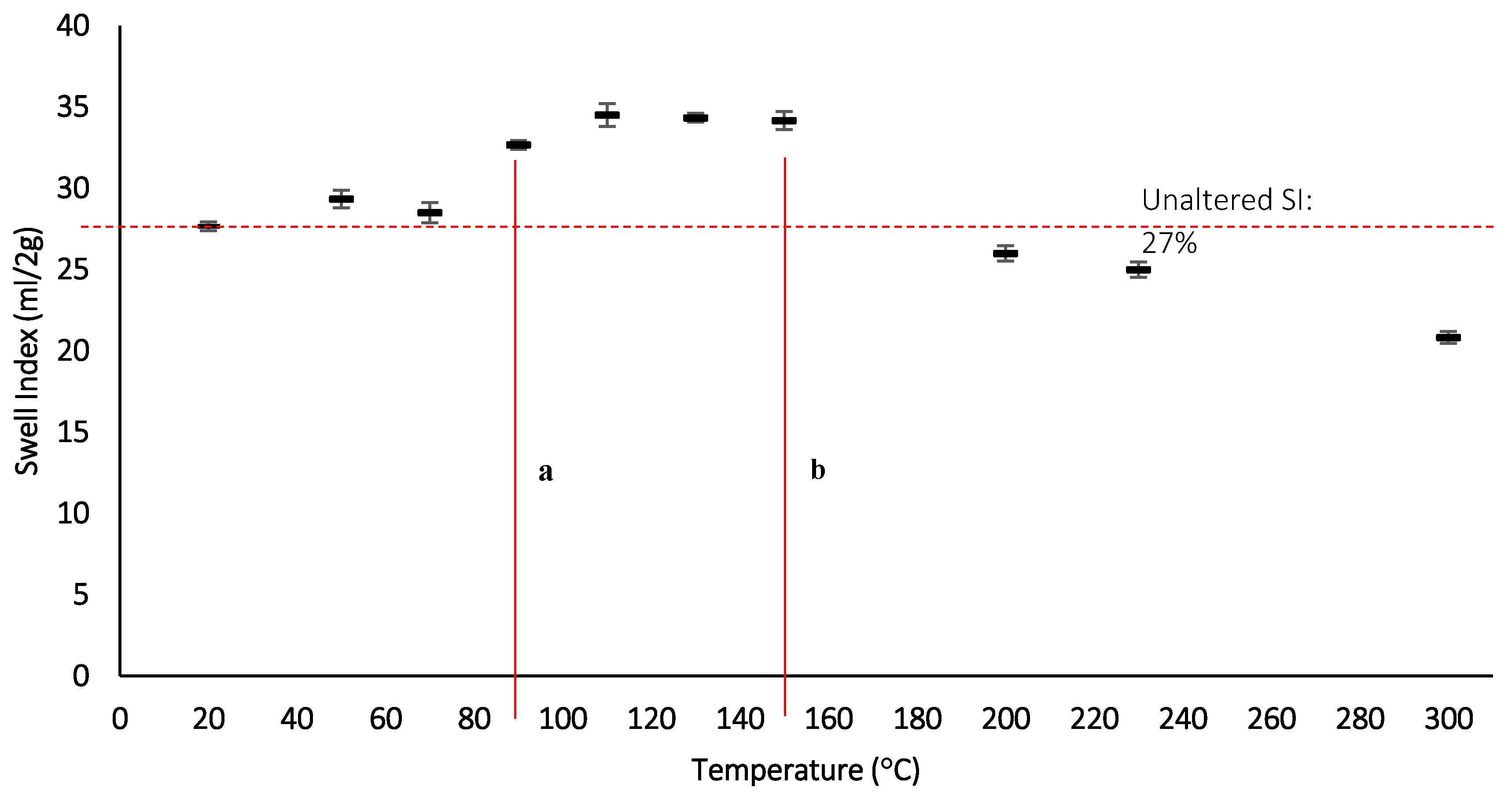
Figure 12.
Swell index measurements with increasing thermal exposure after 24 h, a: lower temperature point where SI increases, b: upper temperature point where after which the SI reduces.
Figure 12.
Swell index measurements with increasing thermal exposure after 24 h, a: lower temperature point where SI increases, b: upper temperature point where after which the SI reduces.
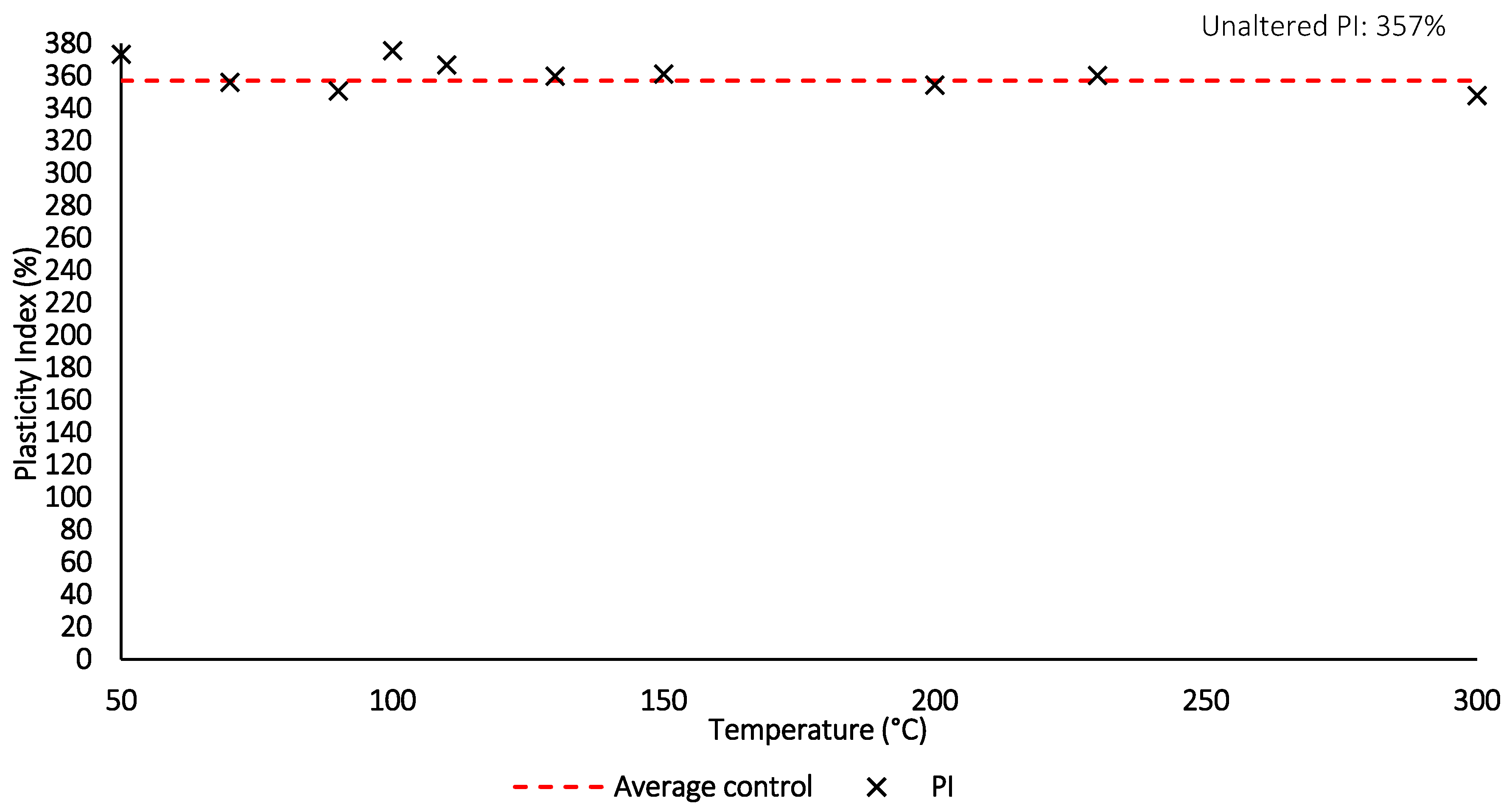
Figure 13.
Plasticity index with increasing thermal exposure for 24 h.
Figure 13.
Plasticity index with increasing thermal exposure for 24 h.
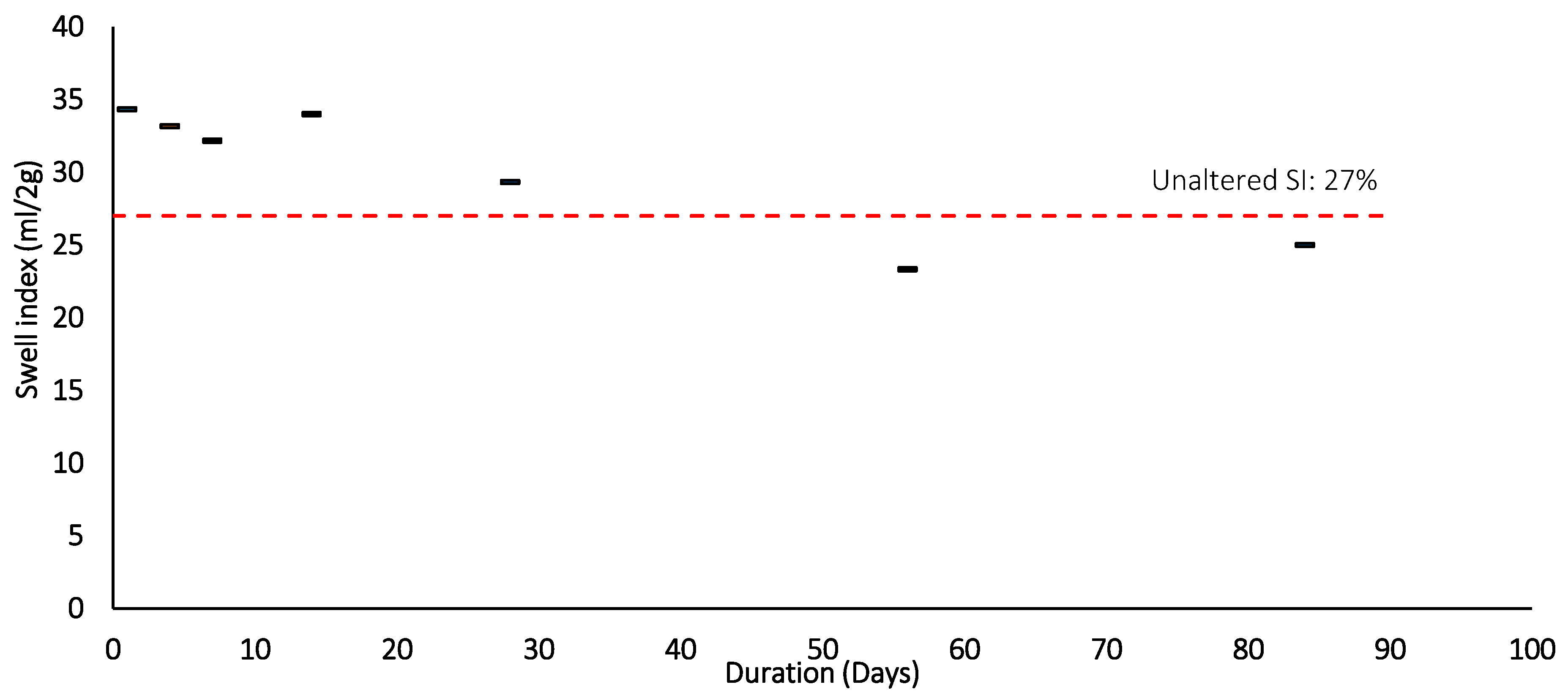
Figure 14.
Swell index after Thermal loading (105 °C) and duration.
Figure 14.
Swell index after Thermal loading (105 °C) and duration.
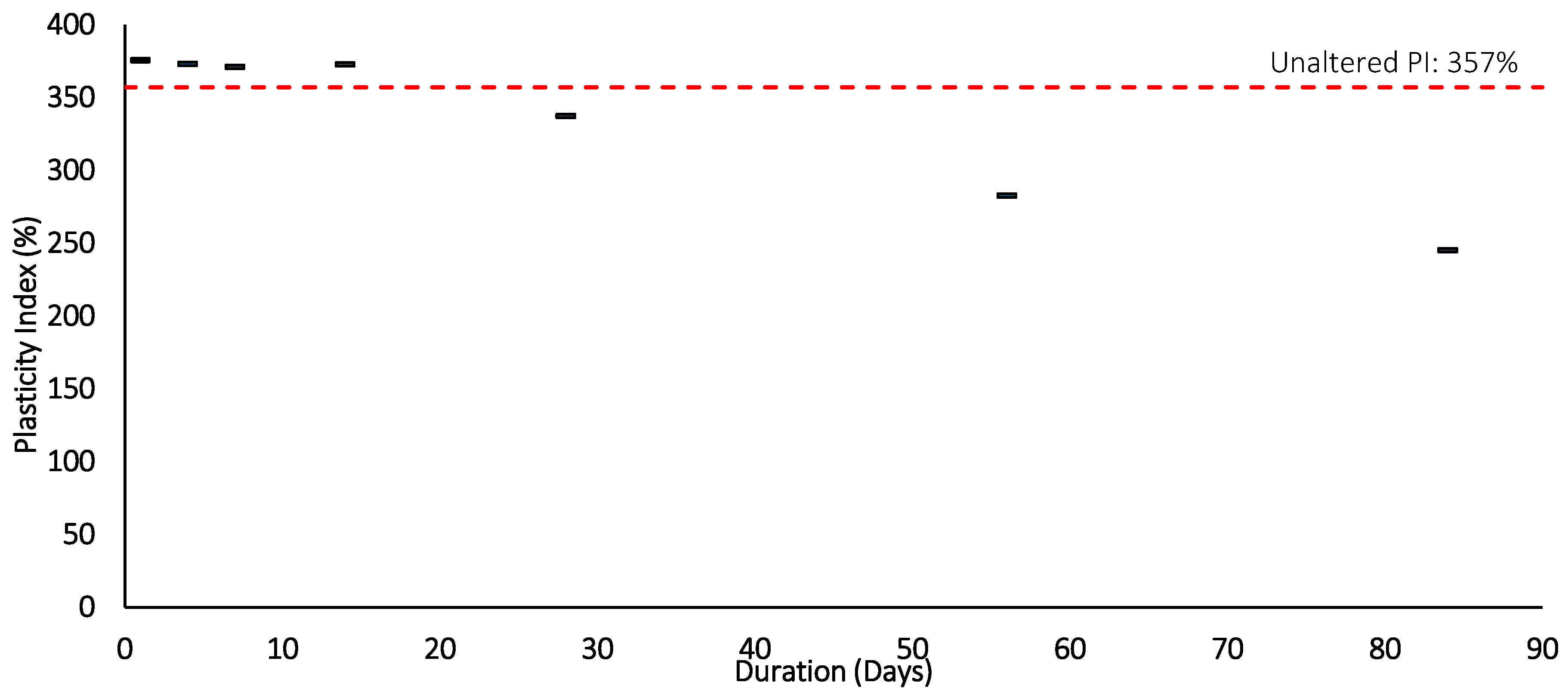
Figure 15.
Plasticity index after Thermal loading (105 °C) and duration.
Figure 15.
Plasticity index after Thermal loading (105 °C) and duration.
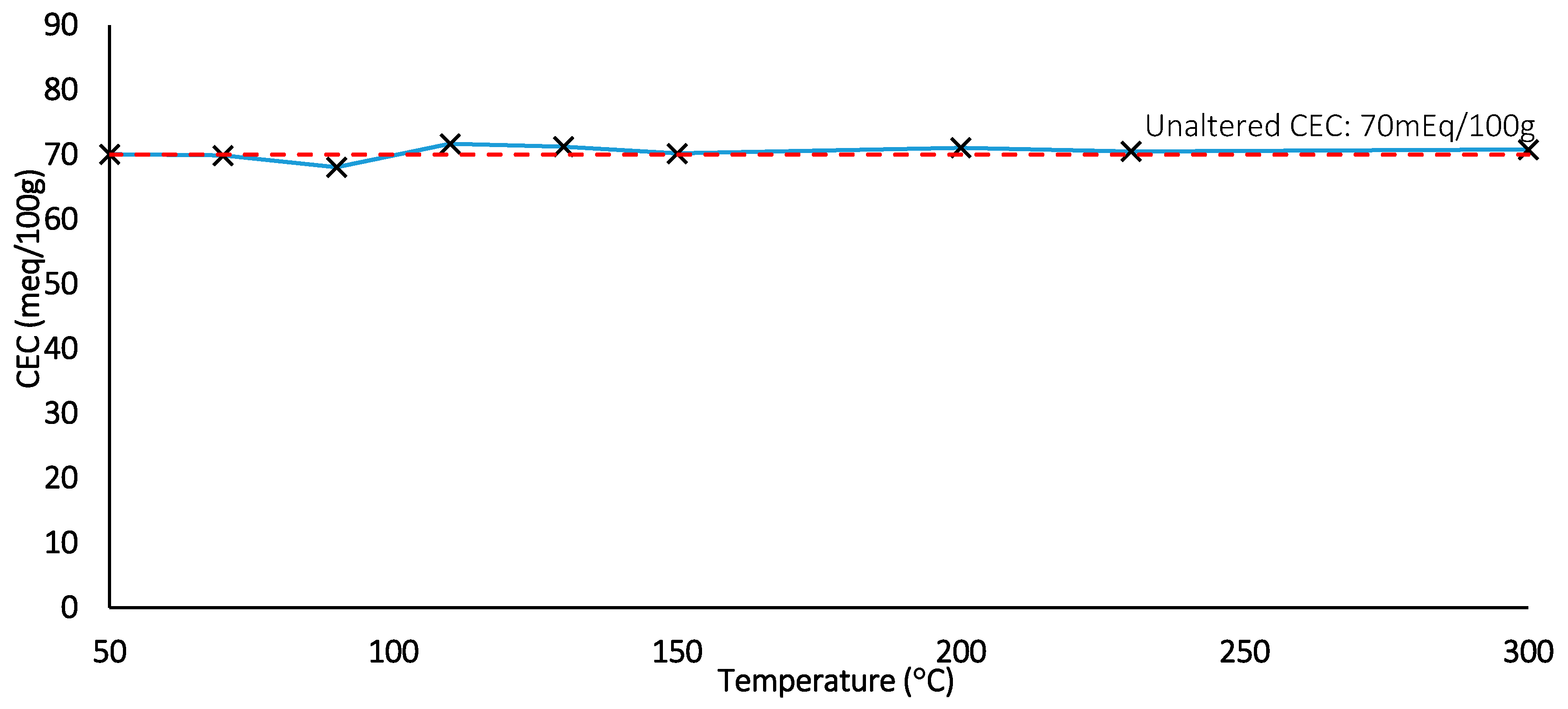
Figure 16.
CEC measurements for thermal loading tests (Dotted line: control).
Figure 16.
CEC measurements for thermal loading tests (Dotted line: control).
Figure 17.
CEC measurement for thermal duration tests (Dotted line: control).
Figure 17.
CEC measurement for thermal duration tests (Dotted line: control).
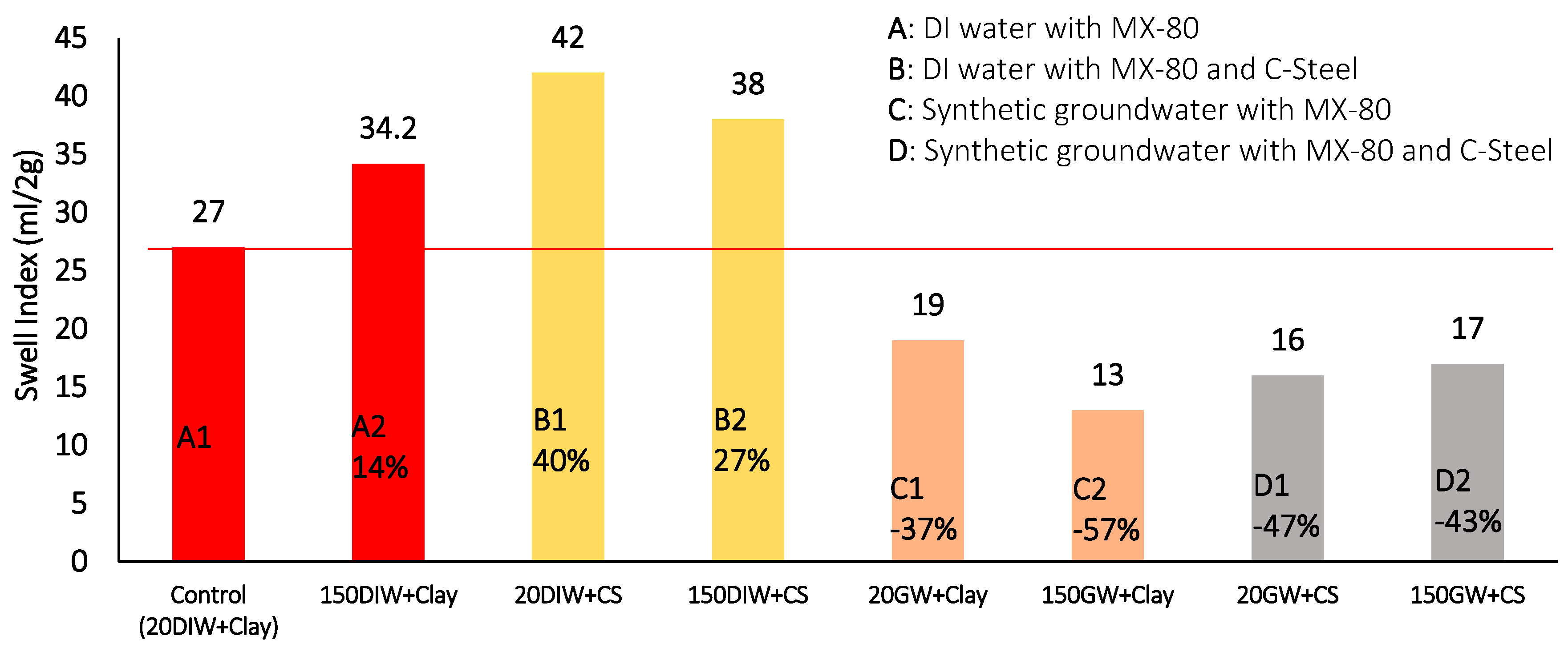
Figure 18.
Swell index measurements at 20 °C and 150 °C for combinations of MX-80, De-Ionised water or synthetic groundwater and carbon steel (The number before the batch code represents the maximum thermal exposure temperature, the lettering system refers to the key, above, for a description of each batch configuration).
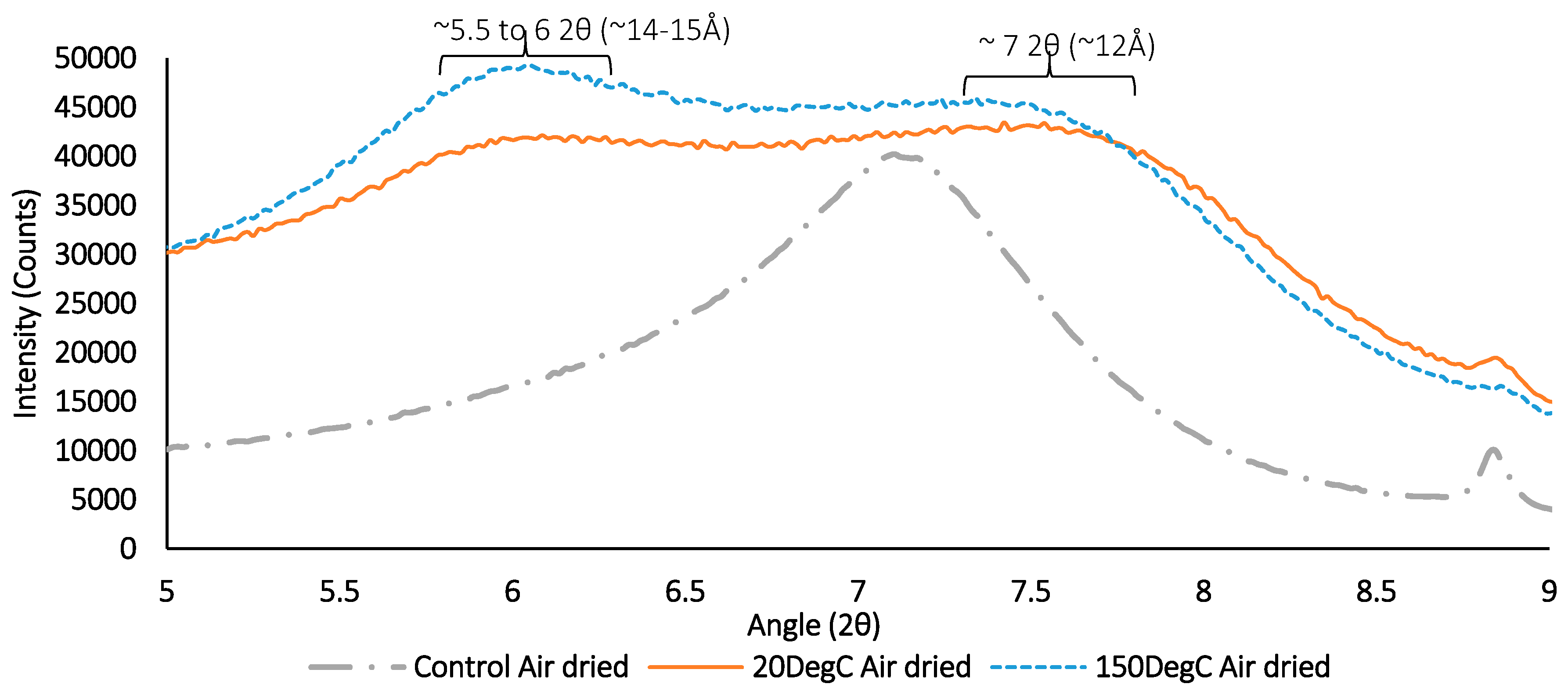
Figure 19.
XRD results for air-dried sample containing synthetic groundwater and clay only with no corrosion products. Exposed to ambient temperature (20 °C) and elevated temperature (150 °C) respectively.
Figure 19.
XRD results for air-dried sample containing synthetic groundwater and clay only with no corrosion products. Exposed to ambient temperature (20 °C) and elevated temperature (150 °C) respectively.
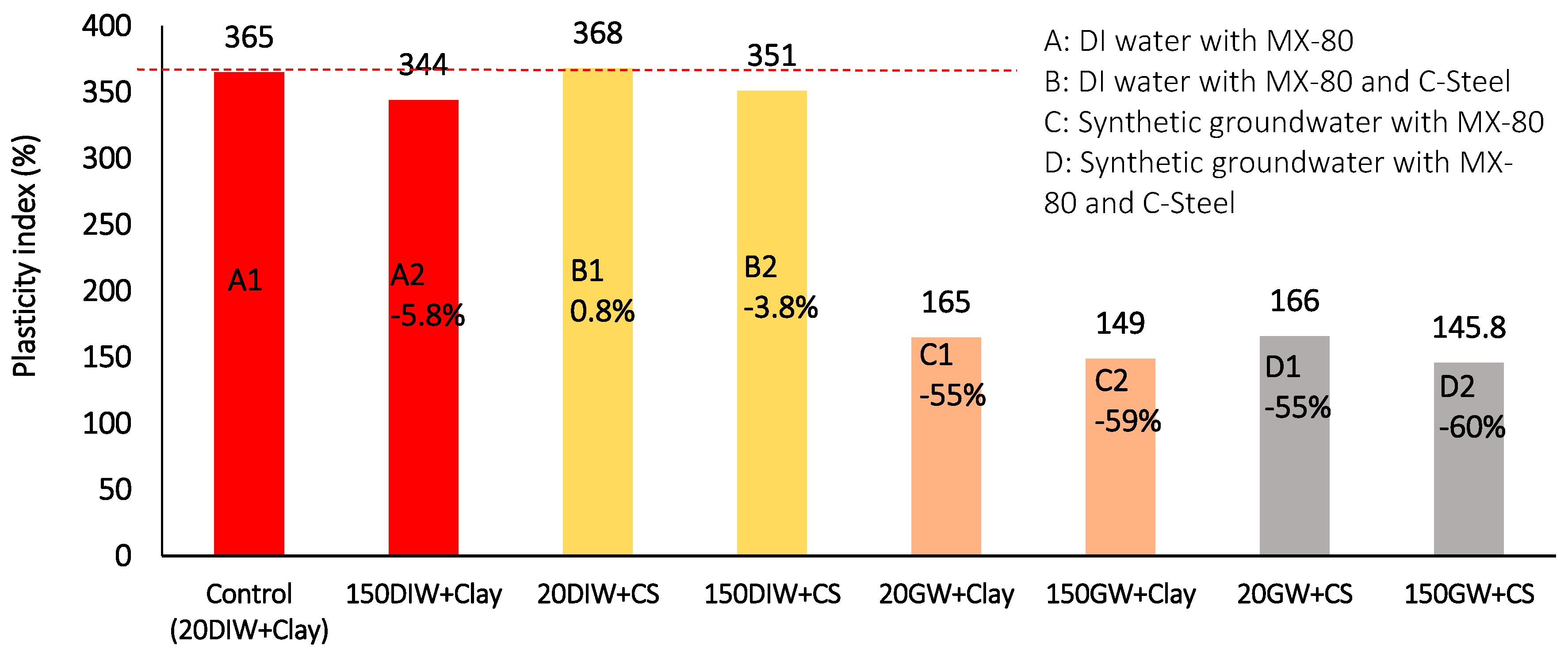
Figure 20.
Plasticity index results at 20 °C and 150 °C for combinations of MX-80, De-Ionised water or synthetic groundwater and carbon steel. (The number before the batch code represents the maximum thermal exposure temperature, the lettering system refers to the key, above, for a description of each batch configuration).
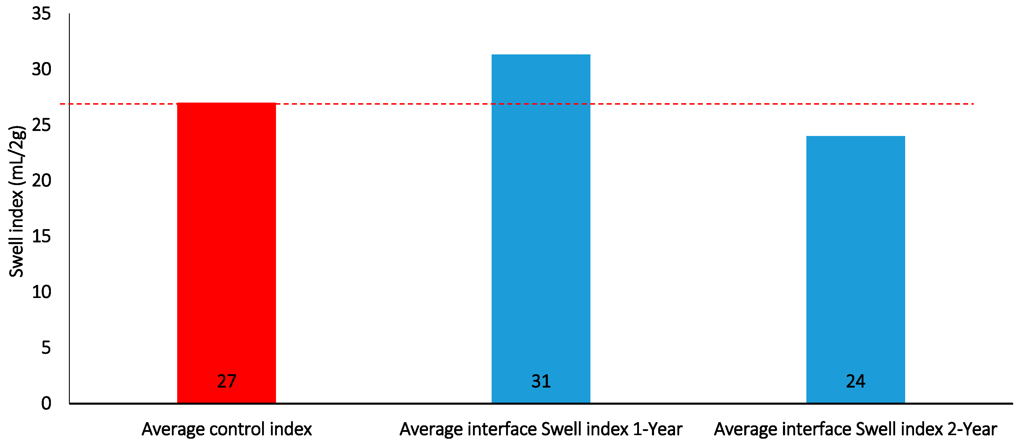
Figure 21.
Interface swell index for 1 and 2-year batch tests.
Figure 21.
Interface swell index for 1 and 2-year batch tests.
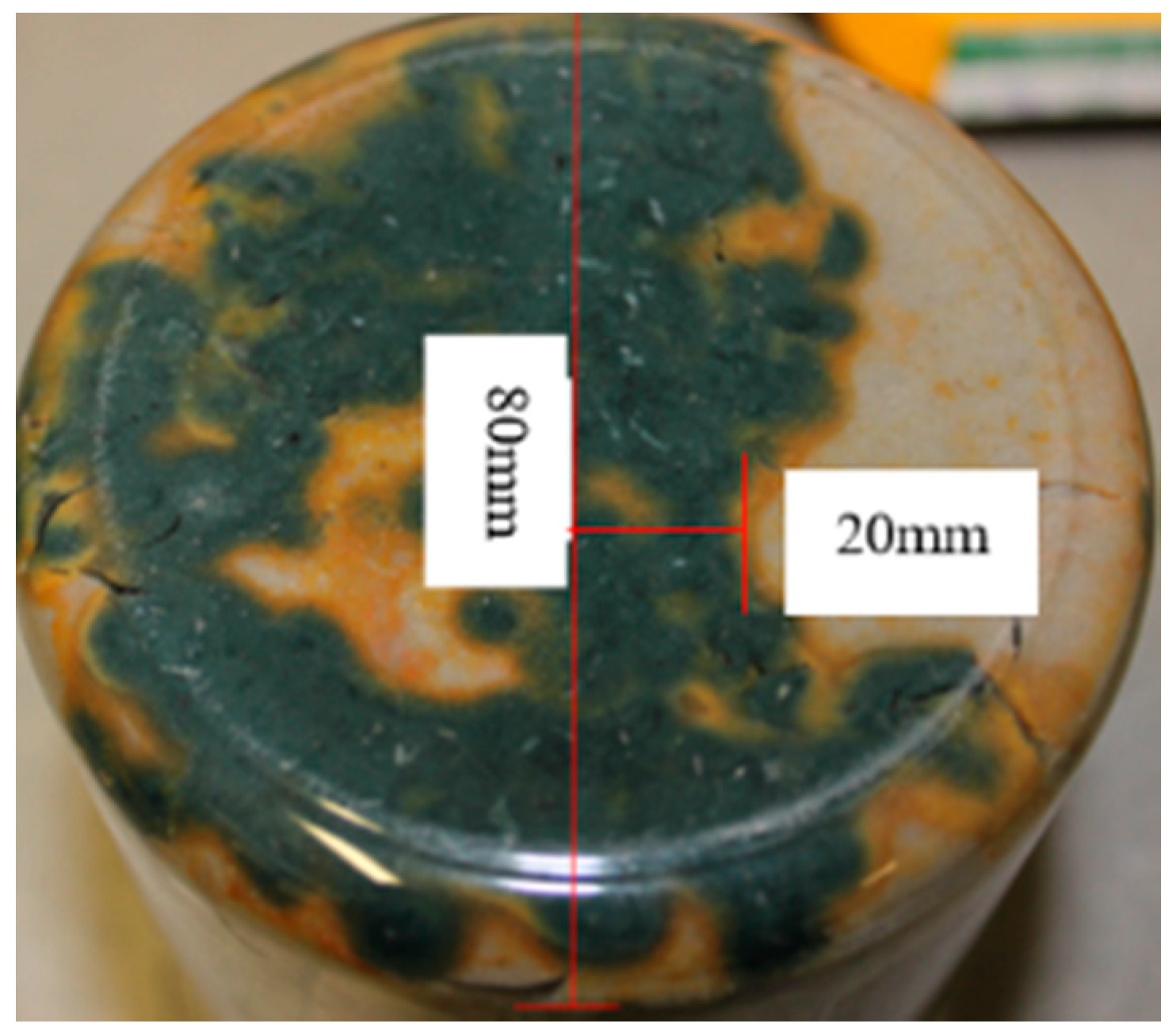
Figure 22.
Development of Greenish-blue corrosion with an Orange corrosion front after 2 year.
Figure 22.
Development of Greenish-blue corrosion with an Orange corrosion front after 2 year.
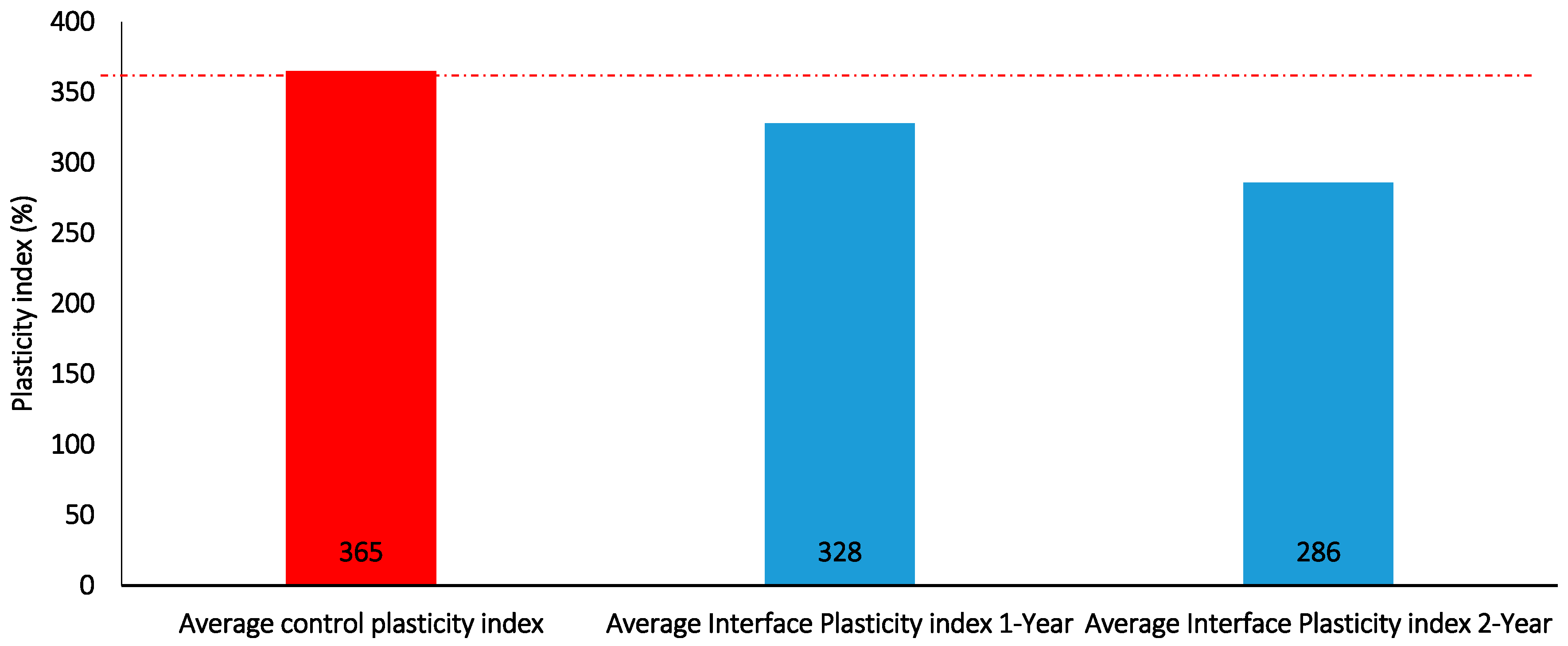
Figure 23.
Interface plasticity index for 1 and 2-year batch tests containing DI water only.
Figure 23.
Interface plasticity index for 1 and 2-year batch tests containing DI water only.
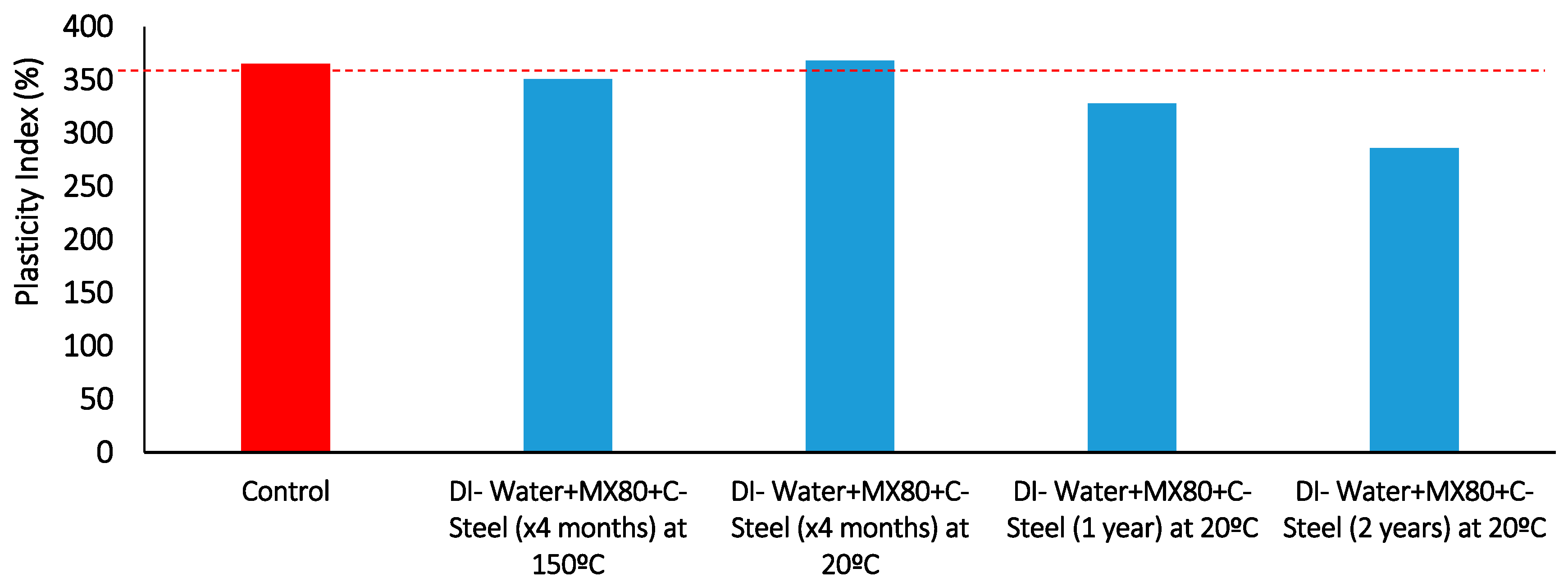
Figure 24.
Plasticity index results comparison of duration vs. Carbon-steel/bentonite interface exposure at 20 °C, also includes one 150 °C result for comparison.
Figure 24.
Plasticity index results comparison of duration vs. Carbon-steel/bentonite interface exposure at 20 °C, also includes one 150 °C result for comparison.
Table 1.
Calculated salt concentrations for a crystalline rock mass at 995 m BGL [
20].
Table 1.
Calculated salt concentrations for a crystalline rock mass at 995 m BGL [
20].
| Salt | Concentration (Molar) |
|---|
| 0.34 |
| 0.135 |
| 0.017 |
Table 2.
Experimental Regime (PI: Plasticity index, SI: Swell index, CEC: Cation exchange capacity, XRD: X-ray diffraction).
Table 2.
Experimental Regime (PI: Plasticity index, SI: Swell index, CEC: Cation exchange capacity, XRD: X-ray diffraction).
| Batch Code | Batch Test Consignment | Description | No. of Samples | Duration (Days) | Temp (°C) | Post Analysis |
|---|
| 1 | Saline profiling | | 12 | 30 | 20 | SI, PI |
| 2 | Steel-Clay-Saline | | 15 | 30 | 20 | SI, PI |
| 3 | High Temperature Steel-Clay-De-Ionised (DI) water | | 3 | 30 | 105 | SI, PI |
| 4 | Thermal Loading and Duration Tests (No Steel, No Salt) | Thermal Loading Tests Over 24 h Thermal Duration Tests at 105 °C ×3 per Duration and Thermal Load
| 39 | 1, 4, 7, 14, 30, 56, 84 | 20, 50, 70, 90, 110, 150 | SI, PI, CEC |
| 5 | Thermal Loading and Duration with High Saline Solution (No Steel) | Powder Samples Each with NaCl, KCl, CaCl and a Synthetic Groundwater Solution Mix 27% (%wt) Investigating Thermal Load and Duration with Salt
| 15 | 56, 84 | 20, 100, 150 | SI, PI, CEC |
| 6 | Steel-Clay-Saline Under Very High Thermal Loading and Prolonged Duration | Varied Boundary Conditions i.e., Steel/Clay with DI Water, Steel/clay with Synthetic Groundwater, Clay with Synthetic Groundwater and Clay with DI Water
| 24 | 120 | 20, 150 | SI, PI, XRD |
| 7 | 1-Year Steel/Clay Interaction Tests | | 3 | 365 | 20 | SI, PI |
| 8 | 2-Year Steel/Clay Interaction Tests (No Saline Solution) | | 3 | 730 | 20 | SI, PI |
Table 3.
Bulk composition of MX-80 [
23].
Table 3.
Bulk composition of MX-80 [
23].
| Mineral Type | % Wt. |
|---|
| Montmorillonite | 94 |
| Gypsum | ≤1 |
| Feldspars | ≤4 |
| Quartz | ≤2 |
Table 4.
Geotechnical measurements for unaltered MX-80.
Table 4.
Geotechnical measurements for unaltered MX-80.
| Material | LL (%) | PL (%) | PI (%) | % CLAY (≤2 µm) | Activity | SI ( |
|---|
| RS® MX80 | 397 | 32 | 365 | 89.41 | 4.08 | 28 |
Table 5.
Fe content and intensity ratios for MX-80 with comparison of common smectite minerals [
22].
Table 5.
Fe content and intensity ratios for MX-80 with comparison of common smectite minerals [
22].
| Mineral Type | Fe Content per Two Octahedral Sites | Intensity Ratio |
|---|
| MX-80 used in study | 0–0.5 | 1.3 |
| Nontronite | 1.7 | 9.5 |
| Saponite | 0–0.5 | 1.5 |
| Pure Montmorillonite | 0.1 | 0.7 |
Table 6.
d-Spacing of the glycolated clay components.
Table 6.
d-Spacing of the glycolated clay components.
| Batch # | d-Spacing (Å) |
|---|
| Control | 17 |
| 20DIW+CS | 16.9 |
| 150DIW+CS | 16.8 |
| 20GW+Clay | 16.9 |
| 150GW+Clay | 16.7 |
| 20GW+CS | 16.9 |
| 150GW+CS | 16.9 |
Table 7.
Compiled 002/003 peak intensity ratios for each batch consignment.
Table 7.
Compiled 002/003 peak intensity ratios for each batch consignment.
| Batch | 002/003 Intensity Ratio |
|---|
| Control | 1.3 |
| 20 °C, DI Water, MX80 and c-steel | 1.1 |
| 150 °C, DI Water, MX80 and c-steel | 1.4 |
| 20 °C, Groundwater and MX80 only | 1.1 |
| 150 °C, Groundwater and MX80 only | 1.1 |
| 20 °C, Groundwater, MX80 and c-steel | 1.1 |
| 150 °C, Groundwater, MX80 and c-steel | 1.1 |
Table 8.
Plasticity index results comparison of duration vs. Carbon-steel/bentonite interface exposure at 20 °C with Deionised water.
Table 8.
Plasticity index results comparison of duration vs. Carbon-steel/bentonite interface exposure at 20 °C with Deionised water.
| Batch (DI Water + MX-80 + Carbon-Steel) | Extent of Visible Corrosion Integration (mm) |
|---|
| 0 |
| 4 months at 20 °C | 15 |
| 1 year at 20 °C | 20 |
| 2 years at 20 °C | 35 |


