Thick-Skinned and Thin-Skinned Tectonics: A Global Perspective

Institute of Geological Sciences, University of Bern, Baltzerstr. 1+3, CH-3012 Bern, Switzerland
Geosciences 2017, 7(3), 71; https://doi.org/10.3390/geosciences7030071
Submission received: 10 July 2017
/
Revised: 26 July 2017
/
Accepted: 7 August 2017
/
Published: 17 August 2017
Abstract
:This paper gives an overview of the large-scale tectonic styles encountered in orogens worldwide. Thin-skinned and thick-skinned tectonics represent two end member styles recognized in mountain ranges. Both styles are encountered in former passive margins of continental plates. Thick-skinned style including the entire crust and possibly the lithospheric mantle are associated with intracontinental contraction. Delamination of subducting continental crust and horizontal protrusion of upper plate crust into the opening gap occurs in the terminal stage of continent-continent collision. Continental crust thinned prior to contraction is likely to develop relatively thin thrust sheets of crystalline basement. A true thin-skinned type requires a detachment layer of sufficient thickness. Thickness of the décollement layer as well as the mechanical contrast between décollement layer and detached cover control the style of folding and thrusting within the detached cover units. In subduction-related orogens, thin- and thick-skinned deformation may occur several hundreds of kilometers from the plate contact zone. Basin inversion resulting from horizontal contraction may lead to the formation of basement uplifts by the combined reactivation of pre-existing normal faults and initiation of new reverse faults. In most orogens thick-skinned and thin-skinned structures both occur and evolve with a pattern where nappe stacking propagates outward and downward.
1. Introduction
The terms “thin-skinned” and “thick-skinned tectonics” is used when describing the overall geometry of fold-and-thrust belts [1]. Hereby thin-skinned tectonics relates to thrust sheets where the sedimentary cover is detached from its crystalline substratum along a décollement layer that consists of mechanically weak rocks. In general the detached cover is piled up to a multifold nappe stack. The thickness of the detached cover sediments is typically on the order of 1 to 10 km (Figure 1A).
Thick-skinned tectonics on the other hand involves thrust faults that reach down into the crystalline basement. In some cases thrust faults run parallel to the basement-cover contact a few kilometers beneath this contact and thus delimit relatively thin basement slices. These may also be piled up to a multifold nappe stack as shown in Figure 1B. This style has been referred to as “basement-involved thin-skinned tectonics” [1]. Thrust faults that reach deep down into the crust and even offset the Moho may broaden to shear zones at depth and lead to a pervasive deformation of the crustal rocks (Figure 1C). As a result such a thick-skinned tectonics, the entire crust is thickened.
The aim of this review paper is to make a comparative analysis of the architecture of mountain ranges based on case studies, to discuss the relation of this architecture to the plate tectonic setting, to compare the sequence of thrust faulting for thin- and thick-skinned types, and to address some of the mechanical aspects of the formation of thin- and thick-skinned tectonic styles.
1.1. Historical Background
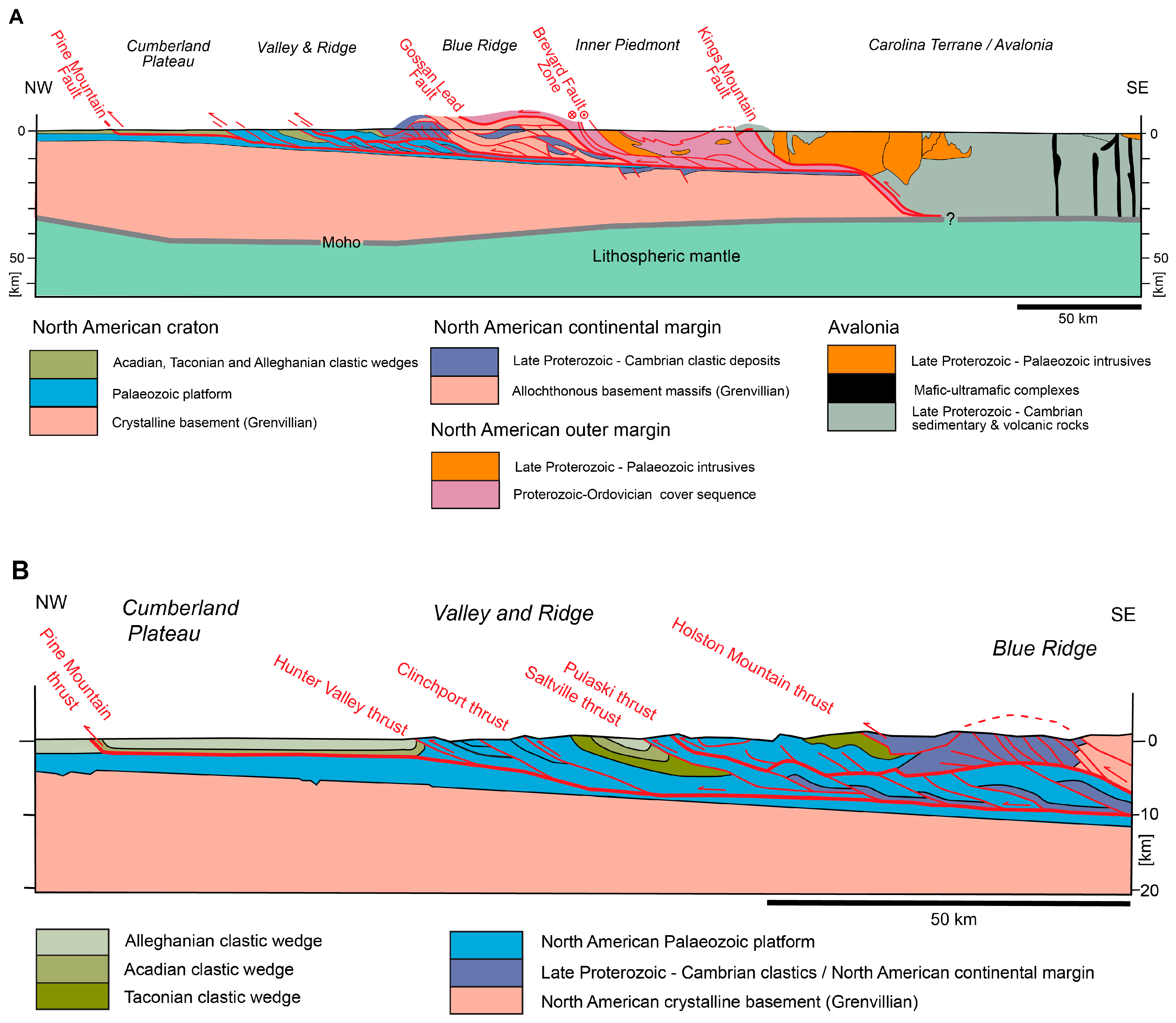
First mention of the question regarding how deep thrust faults extend down into the subsurface occurred in the Colorado Rockies. Here, [2,3] distinguished between thin-shelled and thick-shelled mountain ranges. Reference [4] discussed the question in the Appalachians. In his review on the evolution of our understanding of the Appalachian structures he differentiated between a thin-skinned and a thick-skinned school of thought. Early workers assumed that the thrust faults mapped in the Valley and Ridge Province kept their steep dip observed at the surface to greater depths. It wasn’t until tectonic windows were discovered in the more internal parts of this province that the subsurface continuation of these thrust faults as nearly horizontal structures was recognized. The cross-section by Gwinn [5], shown in Figure 2A, the Blue Ridge is interpreted as autochthonous basement uplift rather than as allochthonous basement thrust sheet.
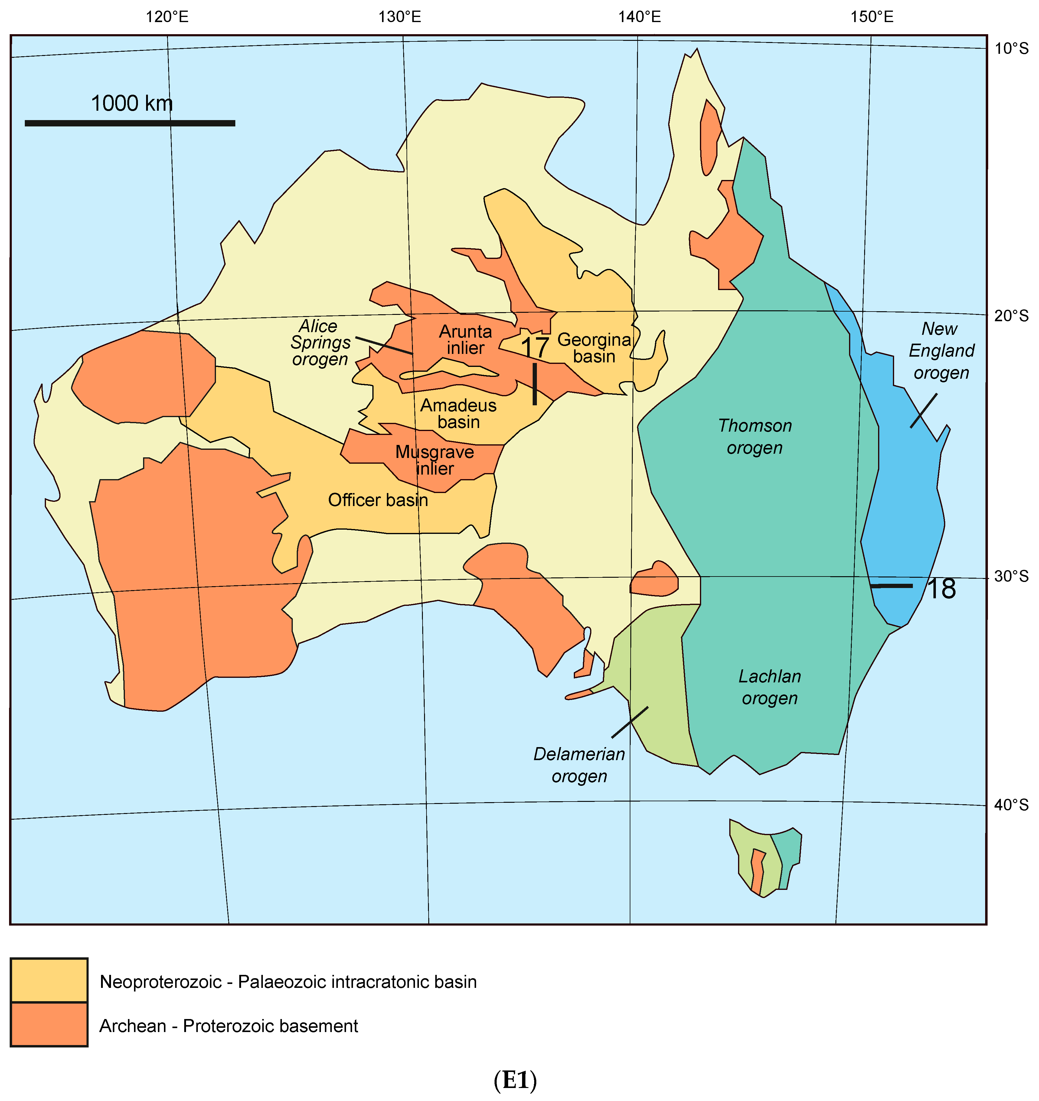
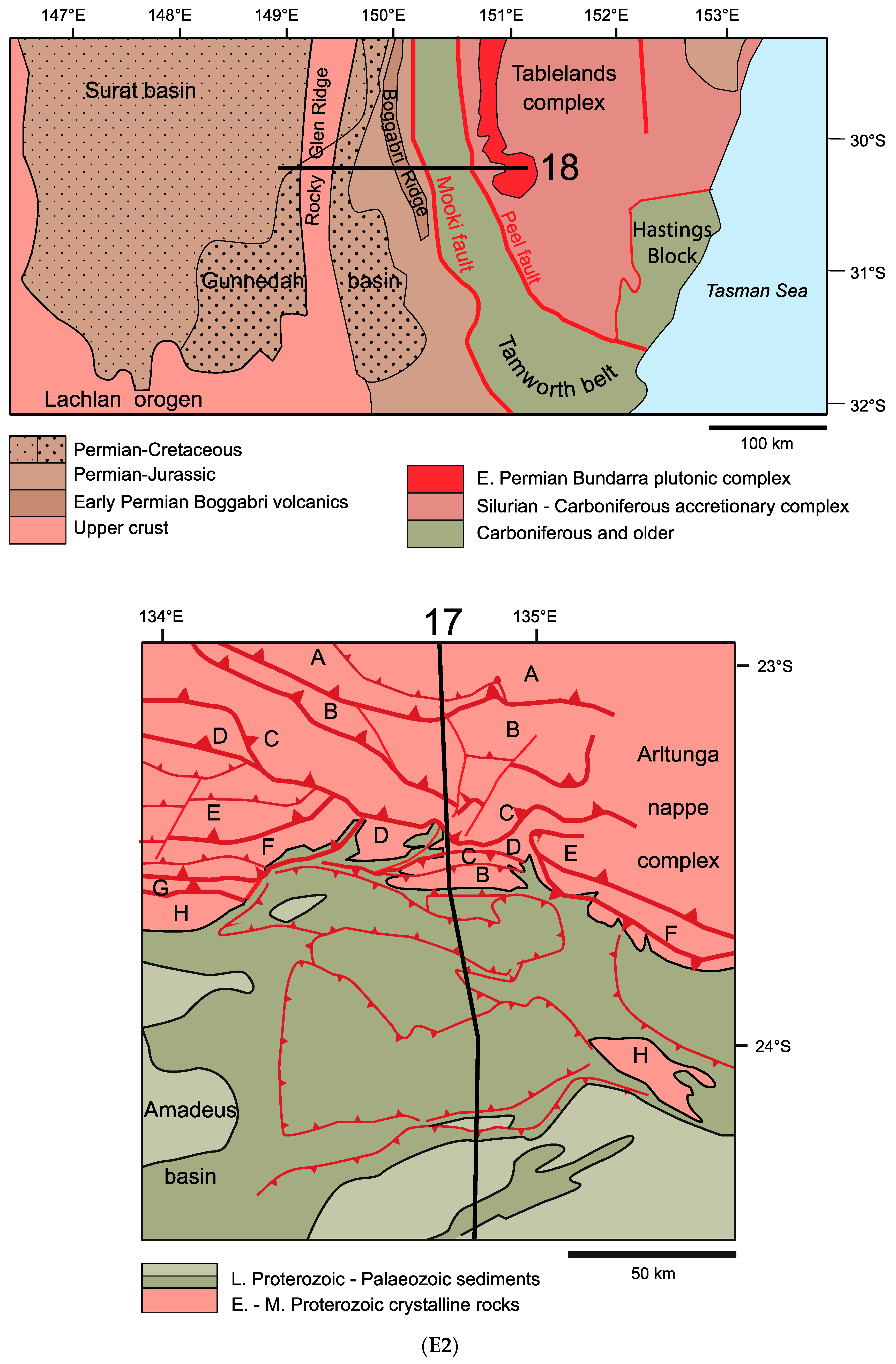
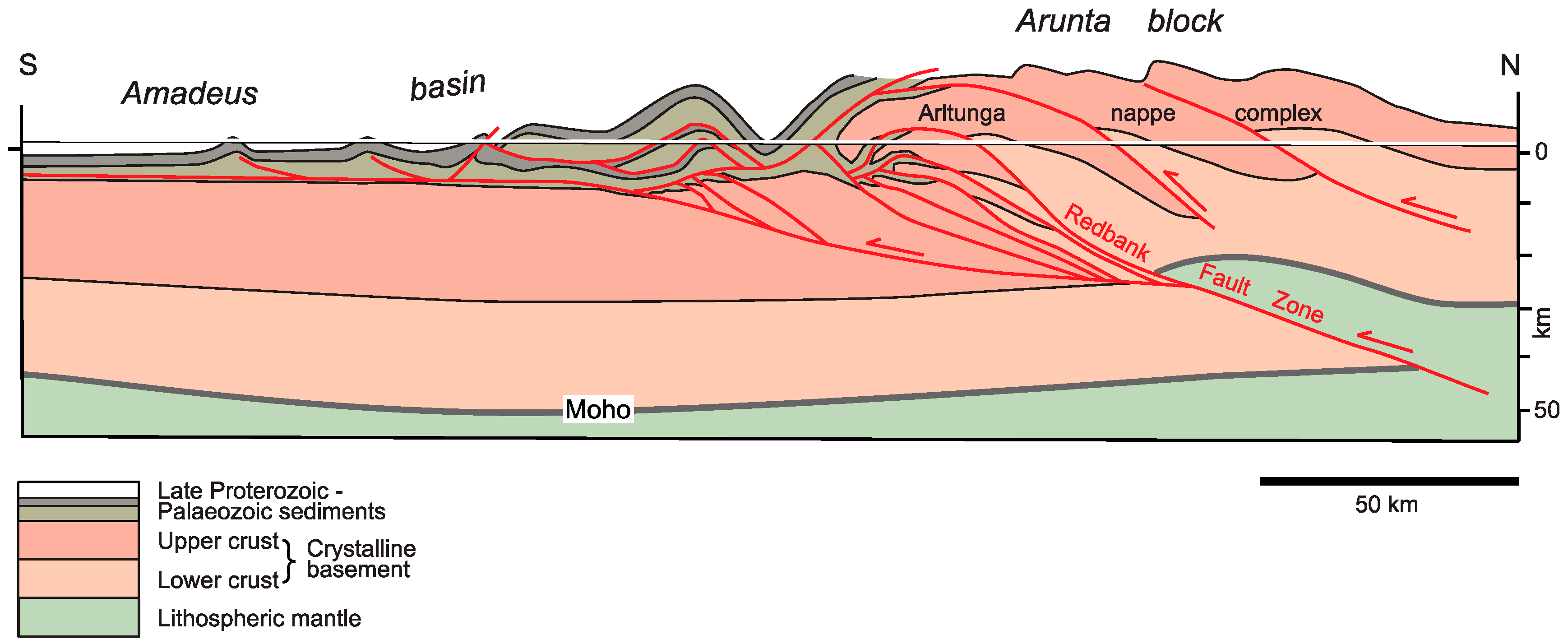
The terminology of thick-skinned and thin-skinned style has been adopted widely. Early workers deciphered the tectonic style by structural mapping and projection techniques. In case of the Alps, references [6] (see Figure 2B) and [7] speculated on the deep structure of the mountain belt and both postulated the existence of thin basement slices. In the Scottish Caledonides, reference [8] produced a large-scale cross-section from existing maps and from down-plunge projection and suggest a basement-involved thin-skinned style (Figure 2C). In the Bhutan Himalaya [9] recognized that the more than 15 km thick sheet of crystalline basement rocks of the Higher Himalaya is thrust onto the Lesser Himalaya along the Main Central Thrust (Figure 2D). Reference [10] speculated that the crystalline basement is involved in a ductile style in the internal part of the Marañon fold-and-thrust belt of the Central Andes of Peru (Figure 2E). In the North American Cordillera work by [11,12,13,14,15], just to name a few, discussed the involvement of crystalline basement in the Sevier, Laramide and Canadian Rocky Mountain fold-and-thrust belts. If the thin-skinned style was widely accepted, the exact nature of structures involving crystalline basement provoked discussions over decades Figure 2F shows a solution proposed by [15] in Wyoming. In the Alice Springs orogeny (Australia) a crustal section involving both lower and upper crust for the Arltunga nappe complex) has been presented by [16]. Figure 2G highlights the thick-skinned nature of this thrust belt.
With more reflection seismic lines gathered for research and hydrocarbon exploration becoming available, mapping of the subsurface structures made a great step forward. As a consequence the discussion on thick-skinned and thin-skinned tectonic styles involved new areas, many of which were of interest for hydrocarbon exploration.
1.2. Thrust Faults and Décollement Layers
Thrust faults were discovered in thin-skinned thrust belts where older strata came to lie on top of younger strata. Early discoveries were made in the Swiss Alps (Glarus thrust; [17]), in the Appalachians [18], in the Scottish Caledonides (Moine thrust; [19,20]) or in the Scandinavian Caledonides [21]. The term “thrust” was coined by Archibald Geikie in Scotland in 1884.
The mechanical problem of moving thrust sheets along a thrust fault has attracted the attention of a number of researchers (see [22] for a review). The “nappe paradox” stated by [23] went to say that a thin and long sheet of rocks cannot be moved by pushing from the rear because the limited strength of the rocks would lead to breaking up of the sheet and thus the stress could not transmitted far enough. They solved the problem by introducing the effect of a fluid pressure at the base of the thrust sheet, thereby reducing the friction. As pointed out by [22], as early as 1909 [24] suggested that a viscous behavior (viscous liquid friction) under geological strain rates would allow the thrust sheet to be moved by push from the rear. A Newtonian or non-Newtonian viscous behavior with a weak basal layer of a thrust sheet was invoked by [25] to move a thrust sheet. All these explanations involve a weak zone at the base of a thrust sheet.
Processes associated with thrust faults and décollement layers have been studied by analog and numerical experiments. A selection of these experiments are documented in the Supplementary material.
1.2.1. Geometric Aspects of Thrust Faults
Thrust faults in sedimentary cover sequences often display uneven fault geometry. Bedding parallel segments following mechanically weak sediments (e.g., shale, marl, evaporite) alternate with ramps where the fault climbs at a high angle across mechanically strong layers (e.g., carbonates).
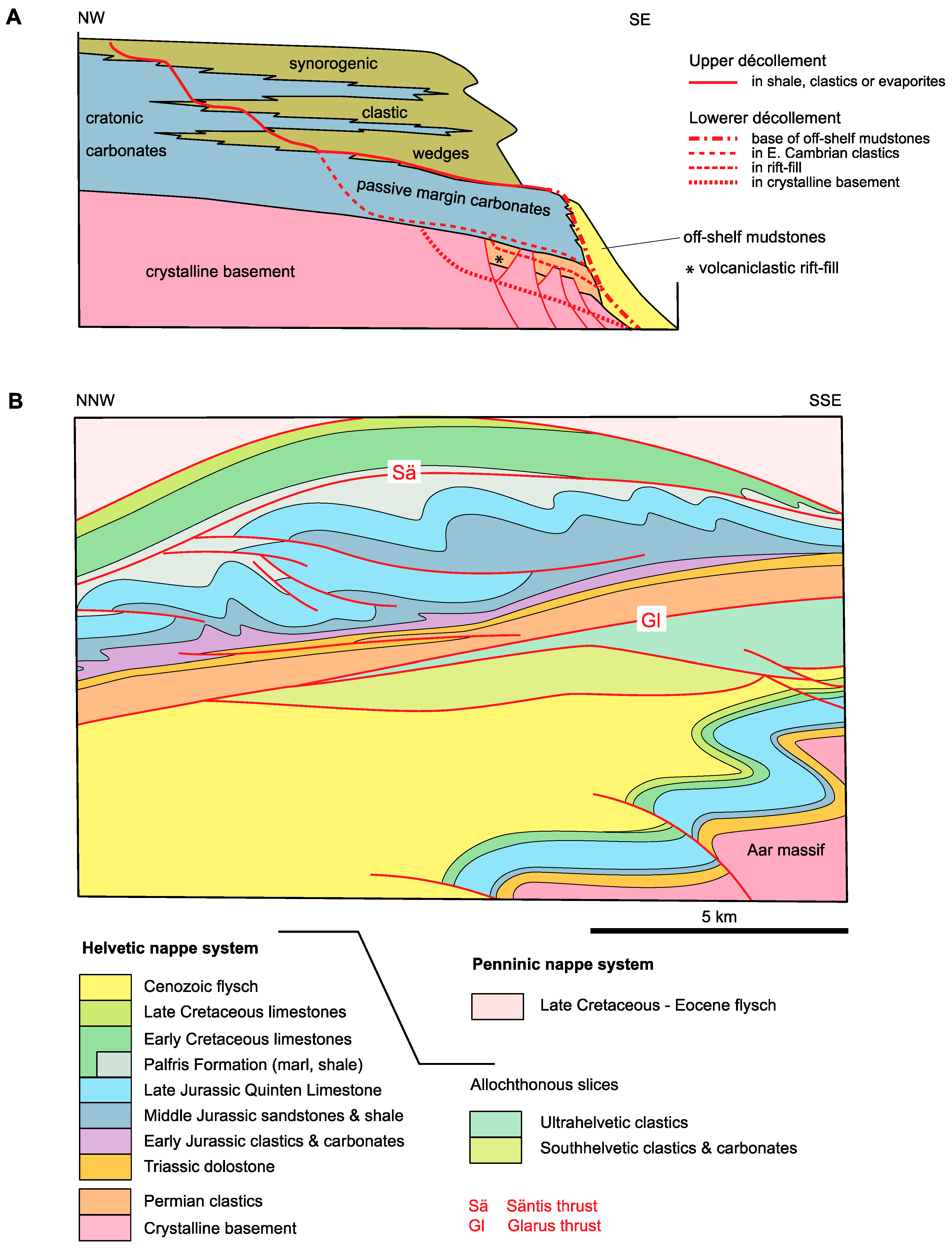
The geometry of such a sedimentary sequence and associated décollement structures has been summarized by [26] for the Appalachians. There, two décollement layers may be distinguished (see Figure 3A). The lower décollement layer lies near the base of the Palaeozoic sequence within the Waynesboro (or the equivalent Rome) Formation, locally within the slightly younger Conasauga Group. These units consist mainly of shale and siltstone, and to a lesser degree of sandstone, dolostone and limestone. Towards the northwest the décollement steps up through a stiff carbonate-dominated layer into an upper décollement. This upper décollement is located within formations of Ordovician to Carboniferous age and differing composition; predominant lithologies include shale, clastics and evaporites. Figure 3A shows the step up of the décollement for areas with thick clastic wedges. In segments where the décollement layer contains evaporites, its thickness underwent significant changes due to folding in the units above. In segments containing shale layers, thickness changes are less pronounced.
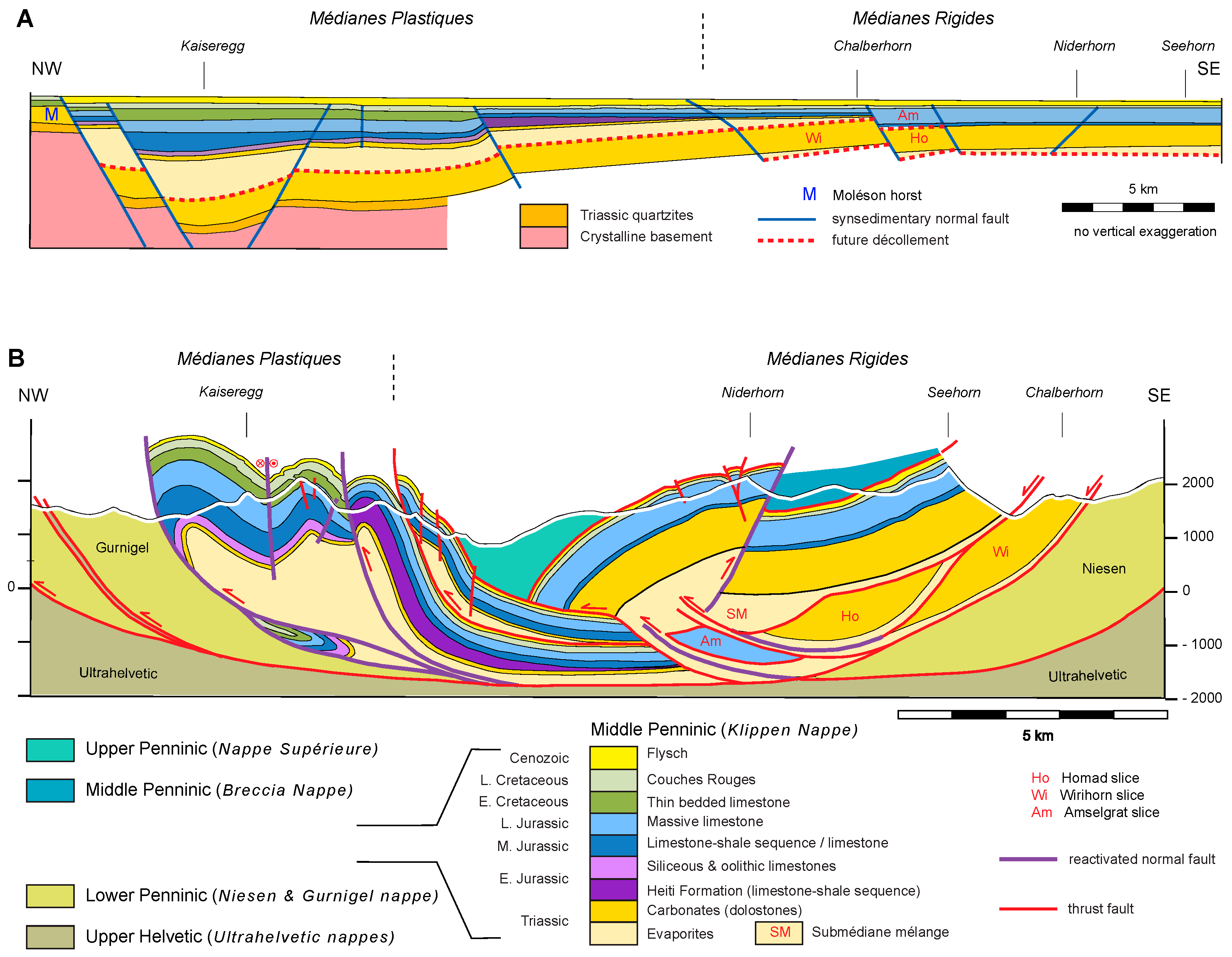
The relative thickness of mechanically weak and strong layers is a key factor controlling the style of deformation in the hanging wall of a décollement. If the décollement layer is thick, detachment folds develop, where the originally thick weak layer is able to fill the cores of anticlines. As can be shown in the Alps, if the ratio between the thicknesses of the weak and the strong layer is small (<0.5) imbricate thrusting occurs [27]. Figure 3B is a cross-section through the Helvetic nappe system in eastern Switzerland. The Glarus thrust is the basal décollement of the Helvetic nappes. An upper décollement in the marl and shale of the Palfris Formation allowed the Cretaceous strata to travel farther north than the underlying Jurassic strata. Between the Glarus thrust and the Säntis thrust, a transition from imbricate thrust faulting in the NNW to detachment folding in the SSE can be observed in the Late Jurassic Quinten Limestone. The Quinten Limestone is a thick and poorly bedded shelf limestone sequence that forms the mechanically stiff layer in the Helvetic nappe system. The thrust faults level off in the underlying Middle Jurassic sandstones and shales, which deform more easily and gradually increase in thickness towards the SSE, the more distal part of the shelf. Thus the change in style is clearly related to the depositional environment of these sediments. Deeper down in the cross-section, in the cover of the Aar massif, the Middle Jurassic sandstones are very thin, and the Palfris Formation is absent altogether. This explains why the cover forms harmonic folds within the Mesozoic strata, which also affect the underlying crystalline basement.
1.2.2. Mechanical Aspects of Thrust Faults
The “nappe paradox” states that the basal friction of a block moving on a fault surface is so high that the block would break apart under the stress associated from a push from the rear [29]. This “model” of a rigid block moving on a basal thrust by push from the rear has been critizied as being unrealistic regarding surface forces versus body forces and moving entirely rigidly with slip occurring simultaneously over the entire length of the fault surface (see discussion in [29,30]). Reference [23] got around the paradox by admitting that pore fluid pressure at the base of the block reduces the friction.
In natural situations of thrust faulting it is appropriate to distinguish between cases with pre-existing zones of weakness and cases where weak zones are newly formed. Pre-existing weak zones are present in sedimentary sequences of thrust belts developed from passive margins. These typically consist of alternating layers of mechanically weak and strong rocks. Weak layers, which serve as décollement horizons, consist of evaporites (salt or anhydrite), shale, thin-bedded sequences of shale and sandstone or mélange formations containing blocks of varying lithologies embedded in a shale rich matrix. Pre-existing décollement layers are typical for thin-skinned tectonics.
Whereas these weak layers provide a priori a reduced resistance at the base of a thrust sheet, several possibilities exist to facilitate slip along thrust faults or narrow shear zones within mechanically strong units. Fluids circulating along a fault contact will reduce the friction on the fault surface [23] and may also contribute to weaking of the neighboring rocks [31]. Strain softening in the course of motion along a fault represents an additional possibility for maintaining a weak fault zone. Strain softening may be considered as resulting from recrystallization associated with grain-scale plastic deformation or, alternatively, from reaction softening [32,33]. These processes are important in the context of thick-skinned tectonics involving crystalline rocks. References [31,32] postulate that mylonitic shear zones in the crust become continually weaker owing to the rising temperatures within the shear zone. Reference [33,34,35,36,37] argue that faults within crystalline basement become weak because of reaction softening: phyllosilicate-rich mylonites (phyllonites) form from the mechanical breakdown of feldspars, which is followed by a chemical breakdown in the presence of a fluid, or grain-size reduction allowing grain-boundary sliding. Reference [38] report that the crystalline basement in the external parts of the Western Alps deformed in a brittle-ductile regime with distributed shear within spaced shear zones or shear bands that are up to a few hundred meters thick. The focusing of deformation into distinct shear zones, in which phyllonite formation is observed [38], corresponds to an overall weakening of the basement blocks. Reference [39] discusses how thrust faults may propagate through crystalline basement by deformation ahead of a propagating fault tip. This deformation is thought to create damage and thus strain weakening. Similarly, [40] argued that crystalline basement rocks weaken with increasing displacement along a thrust fault or fault zone.
1.2.3. Displacement along Thrust Faults
Displacements across a fault are determined in cross-sections from the offset of originally contiguous points in itshanging wall and footwall. If this cross-section is drawn exactly parallel to the transport direction, the measured offset corresponds to a net slip (see discussion in [41]). The determination of the exact transport direction can be very difficult if not impossible owing to the lack of unambiguous criteria. If present, features like stretching lineations or striations on fault surfaces, lateral ramps or branch lines provide criteria [42,43]. In many published cross-sections the transport direction is taken to be perpendicular to the regional fold axes, an assumption that is not always fulfilled and needs careful evaluation. Stretching lineations or reoriented minor folds in the immediate vicinity of a thrust fault are difficult to observe when the fault trace is covered by scree derived from the highly deformed fault rocks.
The displacement (or net slip) along a thrust fault cannot be circumscribed as a single number because, as is the case for any fault or shear zone, it varies along the fault trace. Displacement changes can be gradual caused by differential stretching parallel to the thrust fault in its hanging wall and footwall, or it is abrupt when faults rejoin or splay off a master fault [41]. The changes in displacement are illustrated in the schematic cross-section shown in Figure 4. It is assumed that a higher thrust sheet has its basal thrust entering the cross-section at the lower left and leaving it at the upper right. In the thrust system below this thrust sheet, imbricate thrust faults in the “basement” merge upwards into a single thrust following a décollement layer which in turn splays upward into several imbricates. Displacement along each of the three imbricates in the “basement” increases upward owing to differential stretch in the hanging wall and footwall rocks. As indicated by the length of the double arrows, stretch parallel to the thrust fault is assumed to be higher in the hanging wall. Two of the imbricate thrusts initiate at points A and B, or conversely, do not extend beyond these points down into the “basement”. The sedimentary cover of the basement imbricates is thought to be detached and transported along the major fault following the décollement layer to the right. The detached cover is internally deformed, with imbricate thrust faults splaying off the décollement layer. Going in the direction of motion, every imbricate thrust subtracts displacement from the major fault, and for each of the imbricate faults displacement diminishes upward as the fault ends blind in a fold core. The thrust system ends at point C.
1.2.4. Frontal and Basal Accretion
Multiple thrust faults and thrust sheets stacked on top of each other are typical characteristics for the internal geometry of orogens. At the front of orogens, nappe stacking involves detached cover rocks, whereas at a deeper level crystalline basement rocks are entailed. Nappe stacking increases the volume of the orogen with rock material being accreted at its front and base. Reference [44] studied the factors influencing frontal and basal accretion at collisional margins by numerical modeling and found that the most influential factors are the rheology of the material, surface processes and the balance between inward and outward material flux. These models suggest that a mechanically strong crust with almost fully brittle material behavior develops frontal and basal accretion, which occur independently and spatially separated. The result of one of the critical experiments is shown in Figure 5. This model develops a nappe stack by off-scraping the sedimentary cover rocks along a weak detachment layer early on in the experiment. The thrust faults are numbered in their order of formation (1 through 6) and exhibit in-sequence thrusting from internal to external parts of the model orogen. Crustal material is accumulated as thrust sheets in the core of the model orogen (narrow shear zones are taken as equivalent to thrust faults). These shear zones are also number in their order of formation and show a downward propagation. Erosion facilitates the subsequent rise of the accreted crustal thrust sheets towards the surface, and gravity spreading in the uppermost part results in extension in the core of the model orogen parallel to the applied horizontal contraction.
Analog experiments on the growth of thrust wedges also demonstrate the importance of erosion and sedimentation on the internal growth and architecture of the wedge. Reference [45] discuss the importance of erosion and could show that basal accretion is directly linked to erosion.
1.2.5. Role of Pre-Existing Normal Faults
For passive margin sequences as discussed above for the Appalachians and the Helvetic domain, thickness variations are mostly gradual and the detached cover is of “layered cake” type. Where such sequences are associated with syn-sedimentary normal faulting, the detachment of the cover rocks encounters several problems.
- (1)
- A décollement at the base of the succession is likely to be cut by the extensional faults and if the displacement is of importance, a through going detachment must overcome steps.
- (2)
- The sediments deposited in the hanging wall of syn-sedimentary normal faults are likely to be different from the ones in its footwall. As a result sedimentary strata with different mechanical behavior may be juxtaposed and act as lateral heterogeneity in the course of subsequent horizontal compression and detachment. Numerical experiments suggest that folds develop preferentially at such heterogeneities [46].
- (3)
- In case of syn-sedimentary faulting with steeply dipping normal faults and thick basin fill, the sediments are in part deposited directly adjacent to the crystalline basement. Upon detachment of the basin fill in compression the steep normal faults are ill oriented for reactivation during the expulsion of the basin fill. There is a wealth of literature on this process of “basin inversion” with studies based on numerical and analog experiments as well as on natural examples [47]. Already in 1911 [48] postulated that basement highs and lows inherited from Mesozoic extensional faulting influenced the locations of subsequent compressional tectonics.
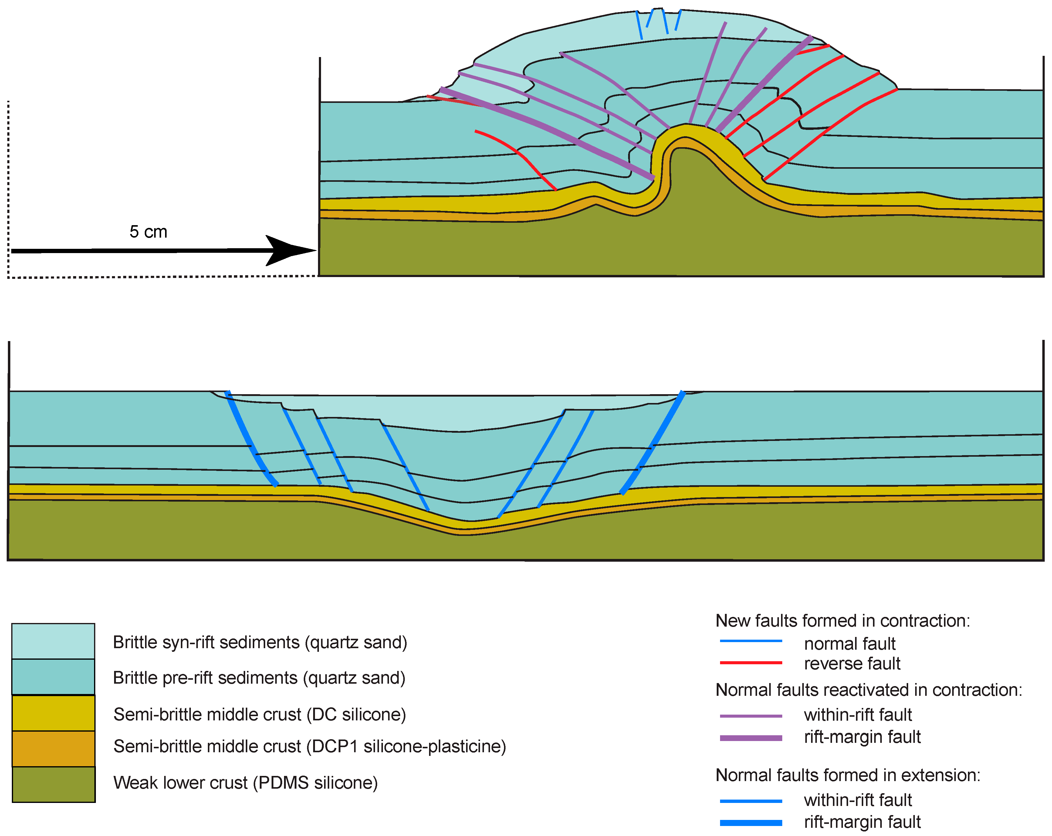
Reference [49] modelled the formation of a symmetric rift followed by coaxial compression and associated inversion of the rift to examine the reactivation of normal faults in compression. The rheological layering of the crust was modeled as a brittle upper crust, a semi-brittle middle crust and a weak lower crust. In the model, the upper crust was represented by pre-rift and syn-rift sediments. The cross-section shown in Figure 6 is from experiment 1 (M17, cross-section a) of [49] and shows the final state after 2.5 cm of extension followed by 5 cm of shortening. Three types of faults may be discerned in the antiformal dome: reactivated normal faults associated with the incipient rift, newly formed reverse faults outside the incipient rift, and newly formed normal faults at the top of the dome within the syn-rift sediments. Upwelling of the model’s weak crust in the core of the dome occurred already in the early stages of shortening and continued throughout the inversion. An important consequence of this upwelling is the rotation of the normal faults within the rift. More specifically, the rift-margin fault rotated from a steep dip of 60° to 65° to less than 45° near the end of the experiment. The displacement along these reactivated faults is relatively small; from which it follows that reactivation was not very efficient. New reverse faults formed outside the rift, the first ones right next to the rift-margin faults, the following successively farther away. The normal faults at the top of the dome formed in the latest stage of inversion as a result of extension related to updoming, All in all it seems that the inversion involved a passive rotation of the model’s upper and middle crust owing to upwelling of the lower crust. The small scale folds visible between the reactivated faults and the new reverse fault indicate that the material between the faults was extended in a direction parallel to the faults, which contributes to the upward escape of material in the course of inversion.
Pre-existing shear zones or intrusive contacts within crystalline basement may focus deformation upon crustal contraction. For example, [50] refer to this process for the nucleation of thrust faults in the Sierras Pampeanas of Argentina where mylonite zones mark the limits between accreted continental fragments (see Section 2.4). In the Alps, [51] postulate that the intrusive contact of the Permian Rofna Porphyry complex was activated as frontal and basal thrust fault of the Suretta nappe during Alpine nappe stacking. For Taiwan, [39] infer that basin-related faults extended deep down into the continental crust and exerted an important control on the structure of the Taiwan orogen. Many other examples could be added here. In many instances, anisotropies within the crystalline basement are held responsible for fault nucleation and geometry in a rather loose way.
1.3. Driving Forces of Nappe Emplacement
A major point of concern in nappe tectonics is the driving forces responsible for movement of nappes. For example [24,25] dealt with a nappe sliding down a slope, while [23] considered motion on a horizontal fault plane. Reference [52,53] considered gravity to play a major role even if the thrust sheet moves uphill. In their model of gravity spreading, the mass responsible for the surface slope α acts as driving force. Reference [52] derived an equation for the shear stress τ at the base of a thrust sheet, which undergoes ductile simple shear in its basal zone that has a minimum thickness of about 5 km
τ = ρgHα
ρ density of the rocks, H the thickness of the thrust sheet and g the gravitational acceleration. In such a model, a steep basal slope, such as for example present at the toe of thrust sheets, will incite compressive surface forces. Reference [54,55] discuss a theoretical model implying horizontal forces pushing an orogenic wedge from the rear. The rocks in the wedge and at its base are on the verge of failure. As the wedge is pushed up the basal slope, the material within the wedge deforms to attain the critical taper geometry in compression. The resistance to shear at the base of the wedge is counteracted by gravity (the surface slope as in the model of [52] and the push from the rear, which depends on the taper angle.
Buoyancy is a force moving low-density rock volumes upward towards the surface. Apart the well-known phenomena of salt diapirs and mantled gneiss domes, [56,57] show that a buoyant rise (or escape) of crystalline basement blocks, which previously had moved down to greater depth by subduction, represents a feasible way to move crustal blocks upward.
Figure 7 is a very schematic graphical representation of the possible motors of nappe movement. Body forces caused by gravity tend to spread the mountain range and reduce the surface slope. A horizontal push is required to stem up thrust sheets on steeply dipping thrust faults. These forces may be explained by the convergence of the two plates. Buoyant rise is envisaged to affect deeply buried slices of continental crust [57]. Such a buoyant rise is likely to affect the rocks above the rising material as well.
As pointed out by many authors (for example [58] and references therein), erosion also affects the uphill motion and thickening of thrust sheets. In an orogenic wedge erosion will provoke more internal deformation of the wedge, including uphill motion, to get the wedge back into a critical state [54,55]. One may also consider that any rock uplift by motion and thickening of thrust sheets will be enhanced because erosion removes some of the load, which has to be dragged up passively. Numerous numerical and analog models have shown the importance of surface processes (erosion and sedimentation) on the evolution of the internal structure of (model) orogens ([42,59,60,61,62,63] just to name a few). At orogen scale, a mountain range with a crustal root formed in a thick-skinned tectonic style that is submitted to horizontal shortening and to erosional surface processes may decay by “erosional collapse” or “subsurface collapse”, depending on the intensity of erosion [64]. If, according to their model, the removal of material by erosion is compensated by elastic rebound, the mountain range can actually grow.
1.4. Case Studies: Choice and Structure of Presentation
The rationale for the choice of case studies was determined by three conditions:
- The availability of geophysical data, namely seismic sections.
- The presence of extensive previous work regarding structure and tectonics setting.
- Coverage of all the different types of orogens.
For the structure of presentation a distinction was made between active and ancient orogens. Because active orogens also have an early history, some of the orogens appear in both categories. Active orogens, where mountain building processes are directly observable, are discussed first. These samples cover the main types of orogens and specific features regarding thin-skinned and thick-skinned behavior. In the next sections, ancient orogens are grouped according to the prevailing plate tectonic setting (continent-continent collision and subduction), and to specific features related to thin- and thick-skinned tectonics (contraction of large passive margins, basin inversion and classic thin-skinned tectonics involving evaporites and water-saturated sediments).
Although lateral variations of structures in mountain belts are typical, the discussion of structures is performed in 2D cross-sectional view. A 3D discussion of these structures, although important for many aspects, would be beyond the scope of this paper. The interested reader can find information on these variations in the literature cited for individual case studies.
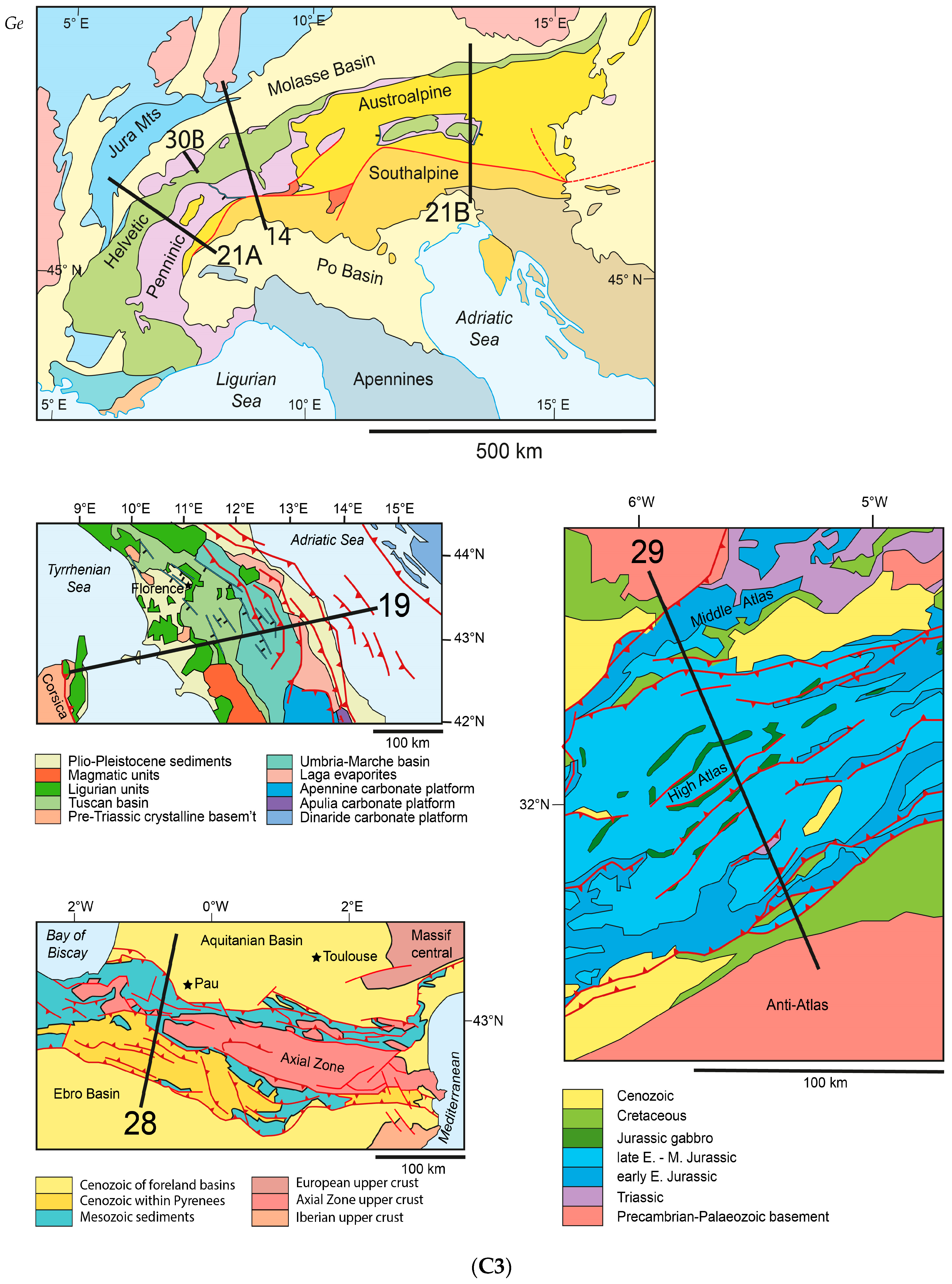
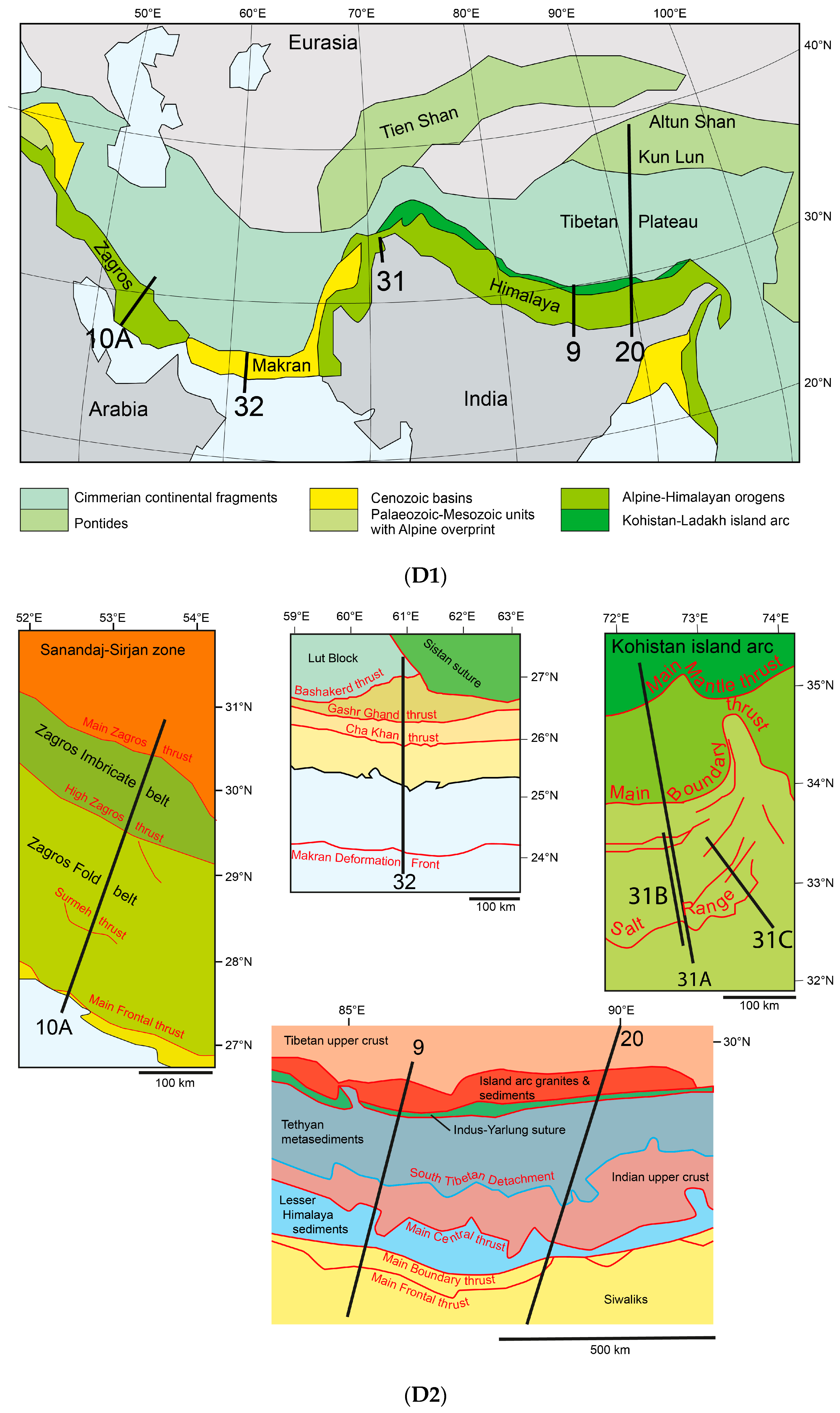
The examples presented cover distinct places on the globe and include several aspects of tectonic style. Some of the case studies are therefore discussed at more than one occasion. In order to avoid a great number of individual structural maps accompanying the cross-sections, structural maps showing the traces of cross-sections are assembled in Figure 8. The labels next to the traces in Figure 8 correspond to the figure number of the cross-sections.
2. Active Mountain Belts
2.1. Himalaya of Nepal
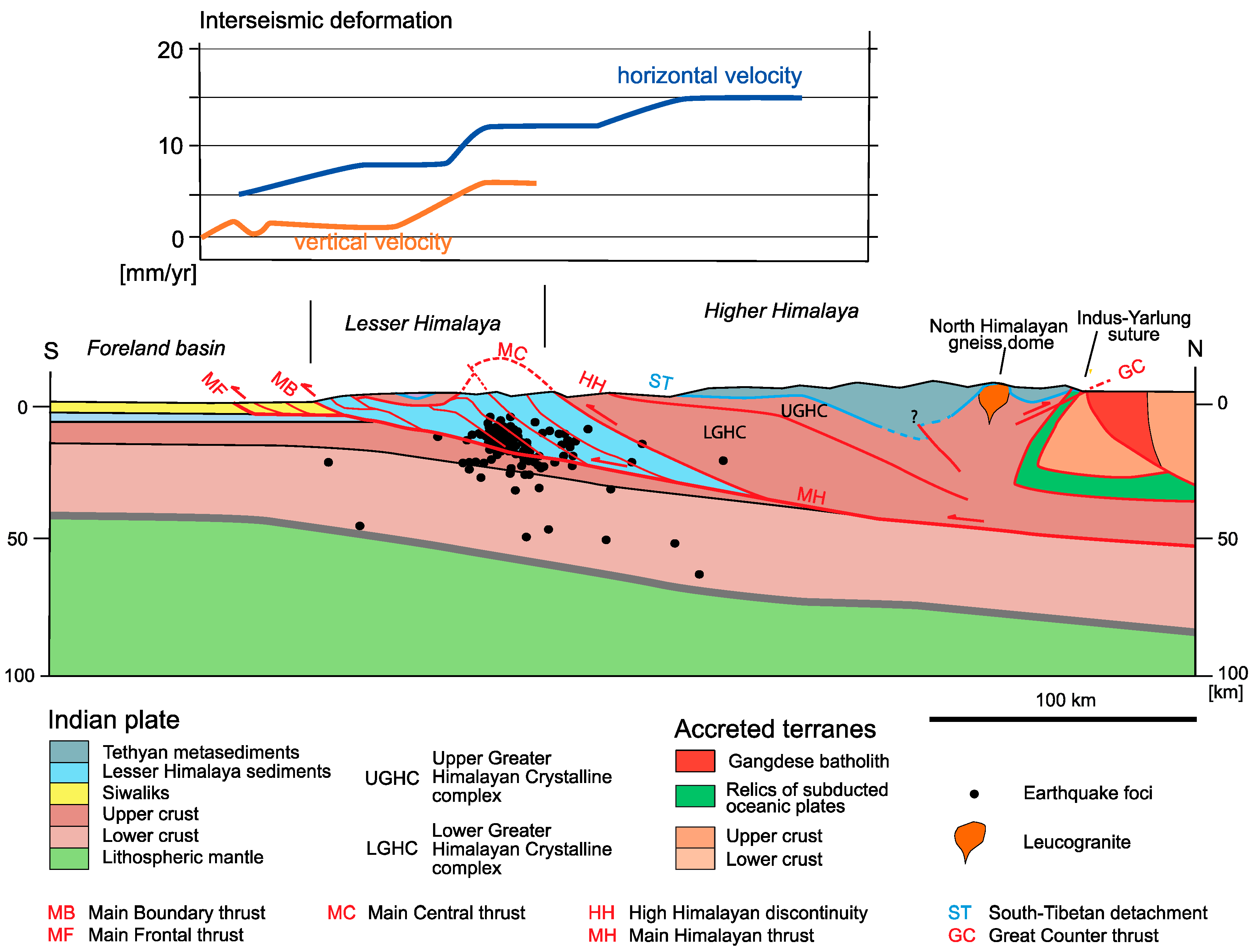
The Himalaya thrust belt is an outstanding example of an active mountain belt where ductile creep and seismic slip along a single important thrust fault, the Main Himalaya thrust, can be observed. For most of its length this thrust fault is located deep in the crust and thus is of thick-skinned nature.
The discussion is centered on a cross section located in the central Himalaya at ~85° E shown (see Figure 9) that is based on [65,66,67,68].
Reference [69] provides an in depth discussion on the structure of the Himalaya thrust belt and highlights lateral changes along strike that affect lithologies and décollement layers, as well as nappe structures. Reference [70] presents a summary of the metamorphic overprint of the Himalayan rocks. Reference [68] gives an in-depth discussion of the entire thrust belt including geophysical, geodetic and thermochronometric data bearing witness to the recent activity of the Himalaya thrust belt. Generally speaking, four major units are distinguished in the Himalayan thrust belt, from top to bottom: the Tethyan Himalaya, the Greater Himalaya Crystalline complex, the Lesser Himalaya thrust belt and the Sub-Himalaya.
The Tethyan Himalaya is a thrust belt consisting of mainly Palaeozoic–Mesozoic sediments that are unmetamorphosed with a local amphibolite facies overprint [70]. Shortening within the Tethyan Himalaya thrust belt amounts to a minimum estimate of 110–140 km (reference [69]). Thrusting started in the Eocene at about 50 Ma and ceased in the Late Miocene at 11–8 Ma.
Unmetamorphosed Palaeozoic sediments of the Tethyan Himalaya overlie high-grade metamorphic rocks of the Great Himalayan Crystalline complex along the South Tibetan detachment. This detachment consists actually of a system of faults forming a fault zone that is a few kilometers thick and contains several subparallel faults and shear zones with top-to-the north and top-to-the south senses of shear [69]. Usually the same Cambrian–Ordovician strata are found in the hanging wall of the South Tibetan detachment, which is indicative for a hanging wall flat. Displacement along this flat cannot be estimated because of the lack of cut-off lines. According to [71] the South Tibetan detachment was active from 27–25 Ma to 17–15 Ma.
The Greater Himalaya Crystalline complex is made of Late Proterozoic-Palaeozoic metasediments that show an upper amphibolite to granulite facies metamorphic overprint [70]. The rocks are intruded by Oligocene-Miocene leucogranites [65]. The upper part of the crystalline complex shows a higher metamorphic overprint compared to the lower part, the limit being marked by a shear zone, the High Himalayan Discontinuity ([2]; see Figure 9). Peak temperatures above this discontinuity reached 700 °C at 32–25 Ma and thus earlier than the 600 °C peak reached in the lower part at 20–16 Ma [72].
The Main Central thrust is the boundary between the high-grade Greater Himalaya Crystalline complex and the underlying less metamorphosed metasediments of the Lesser Himalaya. This thrust fault is characterized by a broad shear zone with the foliation parallel to the thrust contact. The Main Central thrust was active from 23 Ma to 18 Ma [69,73], then became inactive and was crosscut by Lesser Himalaya thrust faults. Reference [73] postulate that the northern segment was (re)activated from 8–3 Ma, while [74] propose that the Main Central thrust has been active throughout the past 20 Myrs. Estimates for the displacement along the Main Central thrust are between 140 and 200 km [65], the last 30 km of which occurred in the past 3 Ma according to [73]. These authors, as well as [74,75] also suggest that the inverse metamorphic zonation observed at the Main Central thrust is the result of basal accretion of slices in the footwall of the thrust in the course of the Miocene-Pliocene phase of its activity.
The Lesser Himalaya thrust belt consists of mainly Proterozoic metasediments with a greenschist to amphibolite facies metamorphic overprint, but the youngest sediments are of Miocene age. According to [76,77] the thrust belt shows a progressive increase in metamorphism towards the top that has been explained by the effect of the overlying “hot” Greater Himalaya Crystalline complex. But as pointed out above, basal accretion is nowadays taken to explain the inverse metamorphic gradient near the Main Central thrust. The Lesser Himalaya thrust belt is a thin-skinned style nappe stack forming a hinterland dipping duplex in the north, which raised the Main Central thrust in its hanging wall (Tamar Kohla dome of [77]) and imbricate thrust sheets in the south. Some of the Lesser Himalaya thrust faults are cut by the Main Central thrust (and thus older), others cut across the Main Central thrust (e.g., the Sun Kosi thrust; [65]). Dating of thrusting is difficult. It possibly started in Late Eocene to Early Oligocene times (41–35 Ma) and lasted into the Late Miocene [69].
The Main Boundary thrust forms the base of the Lesser Himalayan thrust belt. Cenozoic strata outcrop in its footwall, whereas the hanging wall is made of Chlorite-Biotite phyllites, which seem to form the décollement layer. Motion along this thrust fault occurred in Late Miocene to Pliocene times [69] and shortening is estimated to be on the order of 20–50 km [65].
The Sub-Himalaya encompasses Neogene Siwaliks that were shortened by imbricate thrusting with a décollement layer within the Lower Siwaliks [65]. Shortening in this transect is estimated at ~20 km [65]). The Main Frontal thrust represents the outermost thrust fault and puts Neogene Siwaliks onto the Quaternary foreland strata. Deformation is still ongoing.
The Main Frontal, Main Boundary and Main Central thrusts all merge into a basal detachment, the Main Himalayan thrust (see Figure 9). The Main Himalayan thrust forms a ramp beneath the antiform in the northern Lesser Himalaya (the Tamar Khola dome of [77]). As shown by [66,68] this area is characterized by a high seismic activity (shown in Figure 9), which is most likely caused by microseismic slip around the ramp region (and some deformation in the hanging wall and footwall of the Main Himalaya thrust as strain accumulates in the vicinity of the ramp). Simultaneously aseismic creep takes place along the deeper part of the thrust fault. Reference [66] could show that above this seismic zone uplift rates determined from leveling data and horizontal velocities derived from GPS measurements both increase rapidly towards the north (Figure 9, top). These active deformation processes are sustained by a steep elevation gradient above the ramp with average elevation rising from about 2000 to 5000 m a.s.l. [68]. This author concluded that this elevation gradient formed in response to ongoing slip along the Main Himalayan thrust rather than being caused by the Late Miocene reactivation of the thrust as suggested by [73]. Reference [78] discuss the recent Gorkha earthquake (2015) and could show that this earthquake ruptured the Main Himalayan thrust and uplifted the Kathmandu Basin while the High Himalaya farther to the north subsided. The authors also conclude that the Main Himalaya thrust may accommodate all of the active convergence and that there is no need for additional smaller thrust faults. Furthermore they propose that the regional surface uplift occurs during the post-seismic and interseismic phases.
The South Tibetan detachment forms an antiform some 20 km south of the Indus-Yarlung suture (see Figure 9). This antiform has been explained by different mechanisms. Reference [79] express the possibility that the Kangmar dome, one of the North Himalayan gneiss domes located farther east at 91° E, developed above a ramp of the Gyirong-Kangmar thrust, which was active at about 11 Ma. This thrust fault ceases to exist and is not recognized along the traverse of Figure 9; it is therefore indicated as a possible blind thrust. Reference [80] on the other hand postulate that the North Himalyan gneiss domes, which outcrop along the entire Himalaya, are the consequence of buoyant uplift caused by leucogranite intrusions. In case of the domes that they analyzed (Yalashangbo and Ramba), shear senses down-dip of the domes support this idea.
At the northern limit of the Tethyan Himalaya thrust belt, a major south dipping thrust, the Great Counter thrust (also named Renbu-Zedong thrusts) carried these units northwards onto the Indus-Yarlung suture. The Great Counter thrust was active between 25 and 9 Ma, the displacement is at least 38 km but could be much higher [69]. INDEPTH seismic profiling [81] yielded reflections in line Tib-5, which could be related to this thrust fault (e.g., imaging a thick mylonite zone along the fault), and therefore the thrust fault is extended downward into the Greater Himalaya Crystalline complex in Figure 9 over a longer distance. However, it has to be noted that an interference with the leucogranite intrusions cannot be ruled out as the latter are dated between 25 and 15 Ma [72], i.e., contemporaneous to the early history of the Great Counter thrust.
Dating of thrusting by [72] suggests that the South Tibetan detachment was active between 27–25 Ma and 17–15 Ma, the Higher Himalaya Discontinuity shear zone between 25 and 16 Ma, and the Main Central thrust in a first pulse between 23–19 Ma and 18–16 Ma and reactivated between 10–8 Ma and 8–3 Ma. This means that the Main Central thrust was not coeval with but post-dated the South Tibetan detachment, which is an argument against the channel flow mechanism proposed by [82]. According to this model, the High Himalaya metamorphic sequence is interpreted to be extruded southward as a 15–20 km thick sheet bounded by the Main Central thrust beneath and the South Tibetan detachment above.
Regarding the entire Himalaya thrust belt, it is generally accepted that thrusting propagated southwards, the Main Frontal thrust being the last in the sequence. The temporal relationship between thick-skinned and thin-skinned tectonics displayed by the Main Central thrust and the imbricate thrusts within the Lesser Himalaya are complex: thin-skinned thrusting preceded the early Main Central thrust, which in turn was updomed by subsequent thin-skinned thrusting in its footwall. However, the thin-skinned thrusts in the Lesser Himalaya connected at depth with the thick-skinned Main Himalaya thrust, similar to the Main Boundary and Main Frontal thrusts and the recent activity as discussed above. Thus thin-skinned and thick-skinned tectonics are separated in space but not in time. The thick-skinned nature of the Main Central thrust is highlighted by coeval motion along this thrust and deformation of its hanging wall (Great Counter thrust and doming of the South Tibetan detachment).
The entire nappe pile of the Himalaya thrust belt as displayed in Figure 9 shows the thin-skinned tectonic style with a basal detachment along the Main Frontal and the Main Boundary thrusts. The Main Himalaya thrust including the Main Central thrust represent involve a large thrust sheet of upper crustal crystalline basement that has been displaced over at least 200 km [83]. Unlike in many other orogens the rock types that acted as décollement layer within the crust are only accessible where the thrust faults break surface and little is known about the structural evolution of the phyllites and foliated gneisses accompanying the South Tibetan detachment or the Main Central thrust. The northern part of the nappe pile which is in contact with the Indus-Yarlung suture and the Lhasa terrane is also characterized by a thick-skinned tectonic style with pervasive strain in the thermally weakened crust. The detachment of the upper crust from the lower crust and the northward extensionof the lower crust is discussed in more detail in Section 3.1.6.
Reference [71] discussed the Himalaya thrust belt in terms of critical taper theory [84]. Whereas the critical taper theory assumes that the rocks within the wedge are at failure and internal deform of the wedge occurs by imbricate thrusting and folding [84], current deformation within the Himalaya thrust belt is concentrated in one major thrust fault, the Main Himalaya fault [68]. But underplating along the main Himalaya fault and erosion of the Higher Himalaya may maintain a critical taper. From Figure 9 the basal décollement of the Himalaya thrust belt has an average slope of ~ 8° and the average surface slope is = 1.5°.
2.2. Zagros of Iran
The Zagros mountain chain of Iran is made of three major zones which can be followed over 1500 km along strike, the Zagros Fold belt in the SW, the Zaros Imbricate belt (also called Crush zone) and the Sanandaj-Sirjan zone in the NE. These zones are derived from three palaeogeographic domains, the Arabian plate in the SW, the Neotethys Ocean, most of which was subducted, and the Iranian block and Eurasian plate in the NE. The Zagros Fold belt represents the detached and folded cover of the Arabian margin overlying a slightly deformed basement. The Zagros Imbricate belt consists of thin thrust sheets derived from the Neotethys Ocean that have been obducted onto the Arabian margin and were subsequently folded as the cover of the NE distal part of the Arabian margin was detached and gently folded. The Sanandaj-Sirjan zone belongs to a microplate, which was amalgamated with the Iranian-Eurasian plate [85].
The passive margin of the Arabian plate developed starting with Permian rifting and the ensuing opening of Neotethys [86]. Subduction of this ocean started in the Middle Jurassic (170 Ma). As discussed in [6,7,8,9,10,11,12,13,14,15,16,17,18,19,20,21,22,23,24,25,26,27,28,29,30,31,32,33,34,35,36,37,38,39,40,41,42,43,44,45,46,47,48,49,50,51,52,53,54,55,56,57,58,59,60,61,62,63,64,65,66,67,68,69,70,71,72,73,74,75,76,77,78,79,80,81,82,83,84,85,86,87,88], the Zagros mountain chain evolved from a protracted orogeny with several phases:
- (1)
- Obduction of Neotethyan oceanic crust onto the Arabian margin in the Late Cretaceous (~100–70 Ma) which set the starting point for the formation of the Zagros Imbricate zone.
- (2)
- (3)
- Further thrusting in the Zagros Imbricate belt in Eo-Oligocene times [92]. Neotethys was closed by ~35 Ma.
- (4)
Reference [95] estimate a total of ~1300 km of convergence between Arabia and Iran since 56 Ma, of which ~300 km occurred in the time period since 32 Ma. In comparison, as estimated from balancing cross-sections, only 50–89 km [88], resp. 150–180 km [86] of shortening is recorded in the Zagros fold-and-thrust belt to have occurred since the Late Cretaceous.
Several cross-sections across the Zagros have been published (see reviews of [86,88]). In the central Zagros, geophysical traverses determined the geometry of the crust-mantle boundary [88,96] combined the lithospheric structure with a balanced section along more or less the same traverse. This traverse was used for the cross-section shown in Figure 10A. The structure of the Zagros Fold and Imbricate belts are taken from [88], the Moho from [96] and the internal structure of the Sanadaj-Sirjan zone was constructed from the geologic map of Iran compiled by [97].
One of the striking features of the cross-section of the Central Zagros Mountains is the crustal root beneath the Sanandaj-Sirjan zone where the Moho reaches to depths in excess of 60 km. Reference [96] hypothesize that the crustal root reflects a doubling of continental crust by the Main Zagros thrust. In their model the continuation of the Main Zagros thrust in the lithospheric mantel is not discussed and the thickened Arabian crust beneath the Zagros Main thrust is not explained. Reference [88] explain the crustal thickening by crustal thrust faults that cut across the entire Arabian crust and level off in the lowermost crust. In Figure 10A the thrust faults are considered as ending at mid-crustal level. The more external Main Frontal, Surmeh and High Zagros thrusts have all relatively minor displacements which can easily be considered to diminish to nil by differential stretch in their hanging and footwalls (see Figure 3). The nameless crustal thrusts beneath the Zagros Imbricate belt have somewhat higher displacements which could also diminish downward and give way to a more ductile deformation in the more deeply buried lower crust similar to the situation in the Alps discussed later (Section 2.6 and Section 3.1.7) or the Himalaya (Figure 9).
A major change in structural style occurs at the décollement layer located in the Hormuz Formation. The latter consists of salt, anhydrite, dolostone and shale [98], which was originally 1000–1500 m thick but was greatly thickened by halokinesis in the cores of anticlines [93]. The Palaeozoic-Cenozoic sequence above the Hormuz Formation displays relatively open folds. Where the Main Frontal, Surmeh and High Zagros thrust faults break surface the average elevation of the folded strata makes a considerable step owing to the activity of the thrust faults. This point is illustrated in Figure 10B, which shows a detailed section of the Main Frontal thrust in the NW Zagros. It is redrawn and modified from [86] and illustrates the presence of multiple detachments. The Main Frontal thrust is shown to cut through the décollement layer of the Hormuz Formation, which is coring the Anaran anticline. A splay of the fault rejoins a décollement layer located in the Mio-Pliocene Gashsaran Formation. Obviously the Anaran anticline and the associated Main Frontal thrust post-date the deposition of the folded Mio-Pliocene Agha Jari Formation. The offset of the Hormuz décollement by the basement thrust suggests that at this location the thin-skinned deformation of the Arabian cover pre-dates the thick-skinned deformation of the Arabian crust.
In the most internal part of the Zagros Imbricate belt the folds in the detached strata are even more open and also affect the basal thrust fault of the overlying thin thrust sheets derived from the Neotethys Ocean.
The Main Zagros thrust represents the basal thrust of the Sanandaj-Sirjan zone and has a displacement far in excess of the thrust faults in the Folded and Imbricate Zagros. High-pressure/low-temperature assemblages have been described in its hanging wall [90,91], which underline the importance of this thrust fault.
The Sanandaj-Sirjan zone consists of a variety of rock types, including Palaeozoic-Mesozoic sequence overlying crystalline basement, ophiolites, granites of various ages and volcanic rocks (see map by [97]). The cross-section of Figure 10A contains all the units encountered at the surface, but the geometry shown at depth is somewhat speculative.
Deeper down, a slab of Arabian continental lithosphere dips at a very shallow angle beneath the Sandandaj-Sirian zone. The base of the lithosphere slab is at 200 to 250 km depth and its length is at least 600 km according to [99]. The geometry of this slab however changes towards the northwest ([88] for a detailed discussion). Reference [39] summarized the evolution of ideas and constraints regarding the structural style of the Zagros.
Regarding the entire cross-section, the thick-skinned tectonic style in the Arabian crust and the thin-skinned style in the detached cover sequence are obvious. To this regard, [100] analyzed the topography of the Zagros Fold Belt and found a correlation between the breaks in topography and thrust faults within the crystalline basement. They concluded that thick-skinned thrusting causes the topographic slope. An interesting question is whether the thin- and thick-skinned tectonics was contemporaneous. The fact that the Main Frontal, Surmeh and High Zagros thrusts raise the décollement layer and the detached cover unit step-like to a higher level suggests that the thin-skinned detachment occurred prior to the thick-skinned crustal deformation. A similar kinematic sequence is reported from the southeastern Zagros by [93] who date the thin-skinned deformation as Miocene–Pliocene, with an outward propagation of detachment folding, and the thick-skinned deformation as Pliocene–Recent. However, [92] propose a more complex interplay which starts with thick-skinned underplating of the tip of the continental Arabian plate in Early–Middle Miocene times (from ~20–16 Ma to 10 Ma). The thin-skinned detachment folds formed later and more or less coevally starting at around 5.5 Ma and continued throughout the Pliocene. These authors also suggest that, with the exception of the most external basement thrust fault beneath the Main Frontal thrust, the crustal faults beneath the Zagros Fold belt formed in a late phase of the thin-skinned detachment folding. The total shortening of the detached cover amounts to only 15 km [92] or 21 km [86], whereas the Arabian crust was shortened by 50 km according to [92].
The Zagros is known for its pronounced seismic activity. In the following, the discussion of this activity is concentrated along the transect of the Central Zagros illustrated in the cross-section of Figure 10A. References [88,101,102] cover the subject for the entire Zagros. The distribution of earthquake foci along the transect studied here reveals a seismogenic zone which includes the competent group of layers of sediments above the Hormuz Formation as well as the upper crust down to a depth of ~20 km [102]. These authors conclude that shortening related to folding correlates with seismogenic faulting in the cover sediments, while the crystalline basement beneath has a lower seismicity and must therefore be considered as being more rigid or, alternatively, deform aseismically by ductile creep. Farther to the north, in the High Zagros and beneath the Sanandaj-Sirjan zone, the basement deforms by aseismic creep. Focal mechanisms indicate thrusting in the southwestern Zagros Fold belt and strike-slip faulting in the adjacent region to the northeast [101]. Slip vectors determined from thrust faults are nearly parallel to the plate convergence direction (and thus orthogonal to the fold axes), whereas for strike-slip faults slip vectors are more oblique suggesting an extensional component parallel to the orogen [101].
Reference [100] propose a critical wedge model for the Zagros, with a strong brittle upper crust above a weak viscous lower crust. Reference [103] on the other hand concluded from their study that the Zagros as a whole does not fulfill the conditions for an orogenic wedge with critical taper. They reckon that a critical taper geometry can only be assumed for the southwestern most Zagros Fold belt. There internal deformation of the wedge is expressed by seismogenic thrusting in both the upper crust and the sedimentary cover. In their view, only the frontal belt had a critical taper geometry at any moment the past. This belt is thought to have migrated to the SW, towards the foreland in time, and, in the sector behind the critical taper deformation within the wedge continued as aseismic ductile deformation of the basement. This thickening of the crust and the associated surface uplift are thought not to obey the laws of critical taper theory [103]. Reference [104] dated the most recent deformations in the Zagros Fold Belt by means of uplifted fluvial and marine terraces and concluded that the frontal part of the fold belt is currently accounting for much of the shortening fed in by the convergence between the Arabian and Iranian-Eurasian plates. They suggest a mechanism whereby the thin-skinned deformation with decoupling along the Hormuz formation occurs at the very front of the fold belt, whereas coeval thick-skinned crustal deformation takes place farther inboard. There, thick-skinned behavior post-dates locally thin-skinned tectonics because the basement thrusts deform the overlying décollement horizon.
Summing up, the present day situation of the Central Zagros is governed by a very shallow dipping Arabian continental plate dipping to the NE beneath the Eurasian plate. Its lower crust is deforming in a ductile manner absorbing thrust faults from within the upper crust. The crystalline basement of the upper crust is more rigid and deforms by seismogenic faulting. The sedimentary cover of the uppermost crust is detached from the crystalline basement along the Hormuz Formation and shortens by folding. This folding is accompanied by seismogenic faulting, which is of thrust nature at the SW tip of the Zagros Fold belt. The thin-skinned tectonic style of the Zagros Fold belt is locally interrupted by thrust faults emanating from the crystalline basement, which offset the décollement layer. This thick-skinned overprint is mild in comparison to the strain accumulated by detachment folding in the cover sediments.
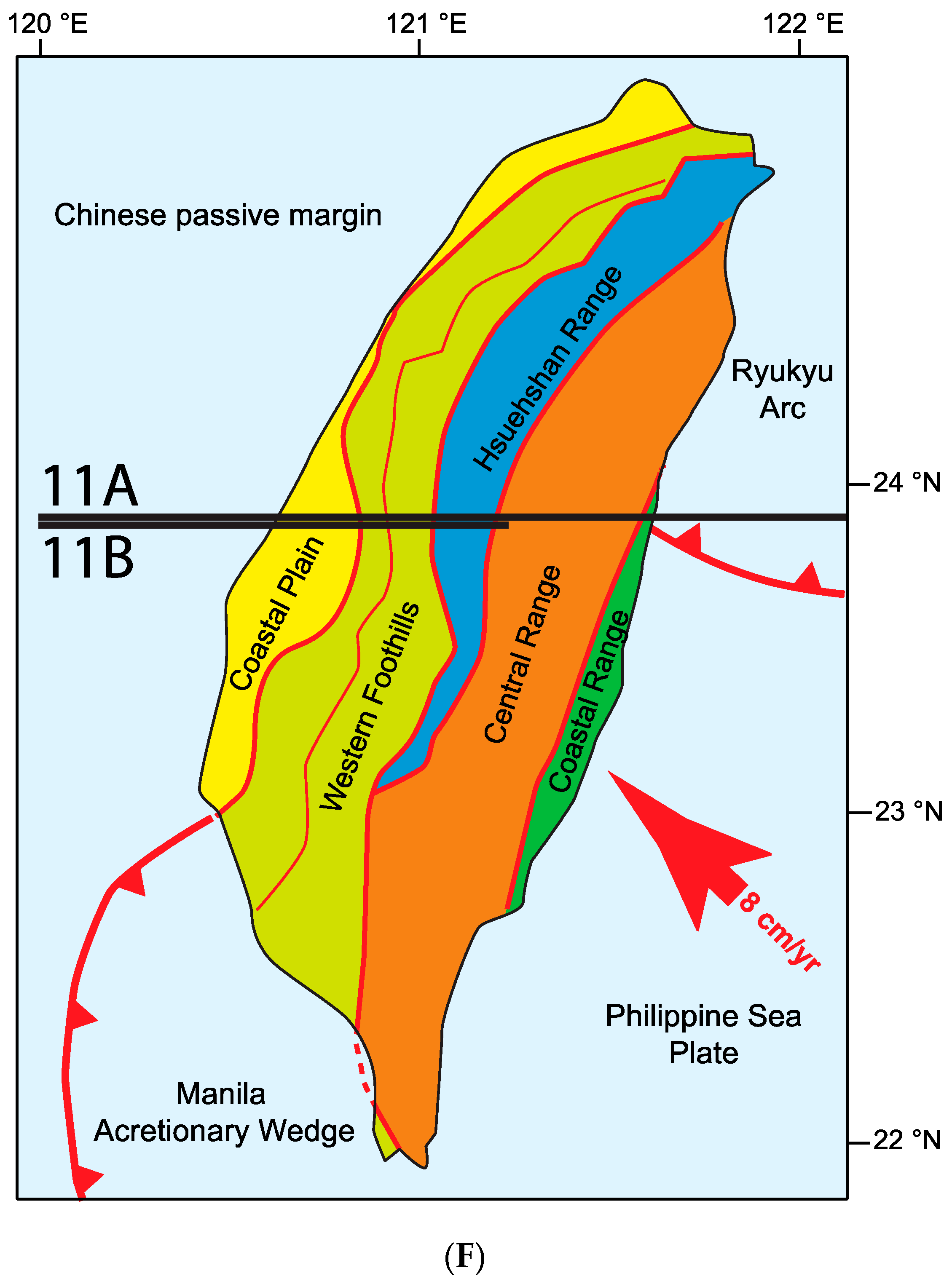
2.3. Taiwan
The Taiwan orogen developed as convergence between the Luzon Island arc of the Philippine Sea plate and the Eurasian plate ended in an arc-continent collision. The arc-continent collision started at ~6.5 Ma [105] and resulted in a mountain belt that started growing between 5 to 4 Ma ([106] and references therein). Recent seismicity suggests that the mountain belt is still growing at the present.
The mountain belt consists of several units aligned more or less parallel to the Taiwan Island. These units represent various stages of the orogeny (e.g., [107]) and are briefly summarized going from east to west:
- (1)
- The Eastern Range, a Miocene volcanic arc with Plio-Pleistocene clastics that developed on the Philippine Sea plate.
- (2)
- The Central Range, which contains a pre-Cenozoic metamorphic complex (Tannao complex) with gneisses, marbles, metaclastics, metabasites, ophiolites and Cretaceous granitoids, all of which are part of an ancient accretionary complex at the tip of the Eurasian plate.
- (3)
- The Backbone Range, which consists of Eocene to Miocene slates that have been metamorphosed up to greenschist grade. Some authors refer to this unit as Slate belt and consider it as part of the Central Range.
- (4)
- The Hsuehshan Range contains quartzites and slates of Eocene–Oligocene age that have been metamorphosed up to greenschist grade.
- (5)
- The Western Foothills are a fold-and-thrust belt consisting of Oligocene to Miocene non-metamorphic sandstones and shales.
- (6)
- The Coastal Plain, underlain by Pliocene to recent clastic sediments.
The pioneer paper by [108] discusses the variation along strike of the thick-skinned Taiwan thrust belt. Reference [39] summarize the evolution of ideas on structural styles based on structural and geophysical data and emphasize the role of inherited structures of the margin.
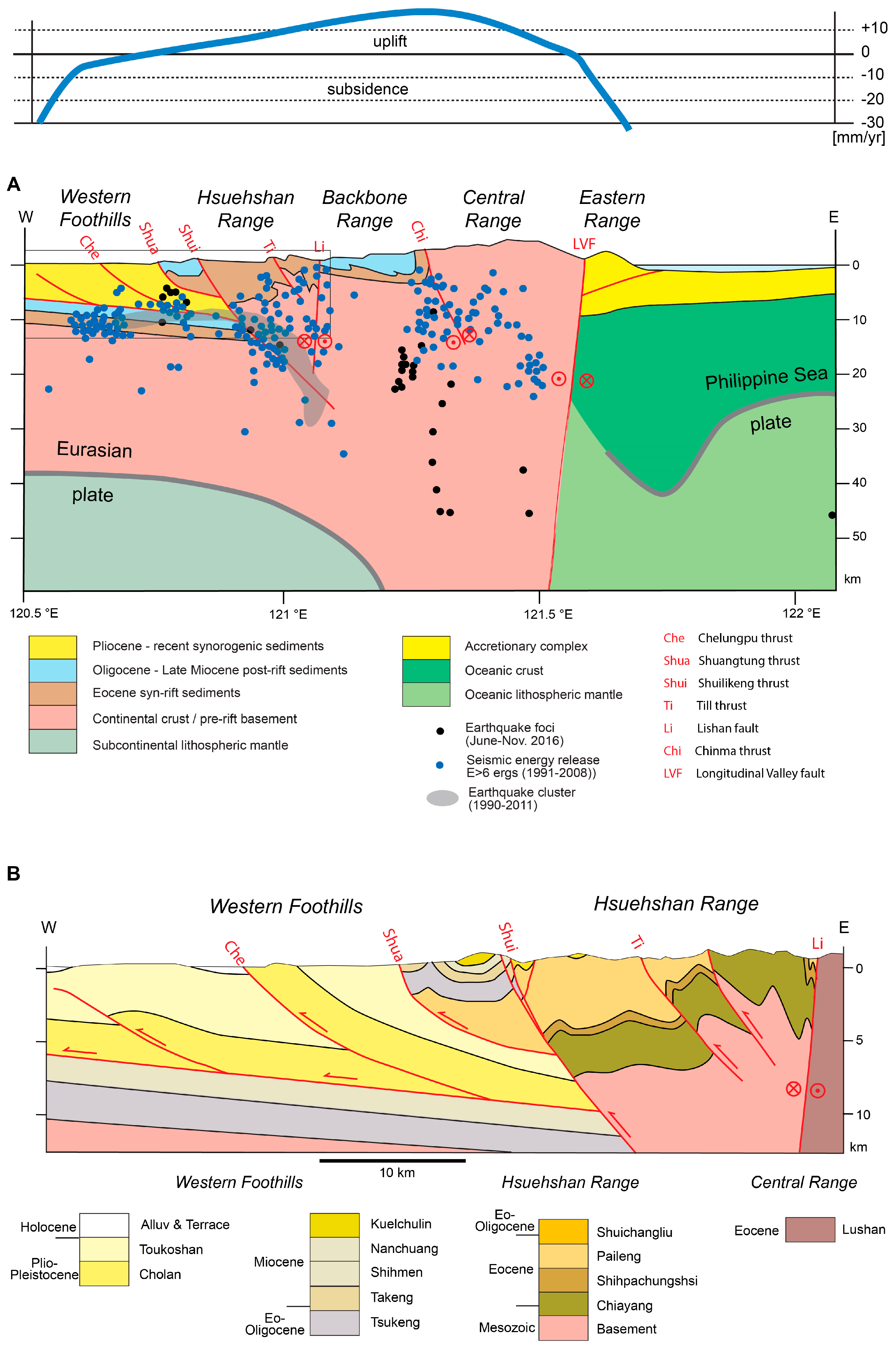
A number of balanced cross-sections have been constructed in the Western Foothills [109,110,111,112], while [106,113,114] elaborated whole-lithosphere sections. The cross-sections by [112] and [114], complemented by the Moho topography of [106] provide a complete view of the orogen across central Taiwan and were used for the cross-sections shown in Figure 11.
The Eocene sediments of the Backbone Range and the Hsuehshan Range formed during rifting of the Eurasian margin, while the Oligocene to Miocene sediments are post-rift, and the Pliocene and younger clastics of the Western Foothills and Coastal Plain represent syn-orogenic sediments [112].
As visible from the general cross-section of Figure 11A, the continental crust of the Eurasian margin thickens from the Western Foothills towards the Central Range. Major, steeply dipping thrust faults (Shuilikeng, Til and Chinma thrusts) are responsible for the vertical uplift of the crustal rocks. In fact, [115] concluded from a study of the metamorphic zonation in the slates of the Backbone Range that the rocks in the core of this Range were exhumed by diapiric folding which took place in a transpressive regime indicated by the strike-slip components of the Lishan fault and the Chinma thrust. As evident from the folds and the Till thrust in the Hsuehshan Range, the uplifted basement blocks were also horizontally shortened. The extension of the Shuilikeng thrust and its intersection with the Lishan fault at depth is speculative. Given the large displacement along the Shuangtung thrust which splays off the Shuilikeng thrust, and the potential connection with the basal detachment in the Western Foothills, it seems likely that the Shuilikeng thrust reaches deep down as indicated in Figure 11A. The area between the Shuilikeng thrust and the Lishan fault is characterized by enhanced seismic activity reaching down to a depth of 30 km [105,116,117], a fact that also points to a deep-reaching fault.
Beneath the Eastern Range, the Moho of the Philippine Sea plate defines a deep synform. Its continuation toward the Longitudinal Valley fault is not backed by any data [106]. Reference [105] suspect a steeply dipping broken off slab of forearc oceanic crust causing the deep position of the Moho, and [118] fill the gap towards the Longitudinal Fault with a Eurasian mantle wedge. In any case the Longitudinal Fault is a deep reaching plate boundary with an important strike-slip component.
The thick-thin-skinned style described above is in contrast to the thin-skinned style suspected from balancing techniques in the Western Foothills as presented by [119] who considered a shallow detachment for the Hsuehshan Range similar to the Western Foothills. Balanced cross-sections respecting basin inversion led [109,110] to the conclusion that basement is involved in thrusting as well. Reference [116] analyzed the distribution of earthquake foci and traced the basal detachment deep into the crystalline basement. They postulate a break in slope beneath the Hsuehshan Range and correlate this steepening with a rise in surface slope. References [111,112] also adopted a thick-skinned tectonic style. Figure 11B is a detail of the western part of Figure 11A. Here, the Chelungpu thrust levels off at depth into a décollement layer at the base of the Pliocene Cholan Fm. An additional, blind thrust is known from seismic data towards the west, which also levels into the same décollement layer. Reference [112] suspect that the décollement layer is even activated still farther to the west. Problematic is the continuation of the décollement to the east, where it meets the Shuilikeng thrust. It is difficult to envisage how the displacement of more than 5 km along the Chelungpu thrust could take place around a sharp bend in the thrust fault. Such an amount of displacement would require important differential stretch in the hanging wall and footwall to let the thrust die out at the sharp bend (see Figure 3). In contrast to the fold and thrust structure in the adjoining Hsuehshan Range, which is constrained by surface data, the internal deformation in the Cholan Fm is basically unknown. Admitting more internal strain than shown in the cross-section, differential stretch could let the décollement end where it intersects with the Shuilikeng thrust. Another possibility is to assume that the Shuilikeng thrust is younger (out-of-sequence) and cuts the Chelungpu thrust.
The present day activity of the Taiwan thrust belt is highlighted by the seismic activity and the uplift rates determined from precise leveling and GPS data. The seismic activity in the cross-section of Figure 11A was compiled from three data sets: clusters of earthquakes in the time period of 1990–2011 [117], the seismic energy release [112], and earthquake foci of the period from June to November 2016 retrieved from the Central Weather Bureau Seismic Network (CWBSN) of Taiwan. In the Western Foothills earthquakes are distributed along a 10 km thick band straddling the décollement level of the detached Pliocene sediments as noted already by [120]. The underlying crystalline basement is also affected by this activity, albeit to a lesser degree. Seismogenic faulting can be recognized in the crystalline basement of the Hsuehshan, Backbone and Central Ranges. Here pronounced clusters of earthquakes are aligned along the potential traces of the Shuilikeng, Lishan and Chinma thrusts.
A compilation of the data on active uplift (and subsidence) of Taiwan can be found in [121]. The curve shown in Figure 11A (top) represents a projection of these data gathered along strike of the cross-section farther south and north. Generally speaking uplift rates are highest in the Backbone and Central Ranges and drop off to subsidence towards the east (Eastern Range) and the west (Western Foothills and Western Coastal Plain). The modern uplift rates are comparable to long-term geological uplift rates except for the Central Range where modern uplift rates are much higher [121]. The modern subsidence rate in the Eastern Range in the transect of Figure 11A is in contradiction with the geologic vertical velocity rate (uplift) and might be due to interseismic elastic deformation according to [121]. Subsidence in the Western Foothills and Western Coastal Plain is explained as resulting from long-term elastic loading of the Eurasian Plate by the Taiwan thrust belt and the withdrawal of water [121].
To explain the dome shaped uplift pattern of the Taiwan thrust belt [121] suggested a model with a thrust fault along the décollement level of the Western Foothills extending into the crystalline basement beneath the Backbone and Central Ranges. Results from analog modeling also suggest such a scenario [63]. However, it has to be remembered that the Lishan, Chinma and Longitudinal Valley faults all have a strike-slip component and are likely to be steeply dipping faults as outlined by the seismicity.
2.4. Sierras Pampeanas of Argentina
The Sierras Pampeanas of Argentina located between 26° and 34° S represent Neogene basement uplifts that formed in the late stages of Andean compression. At this latitude, the subducting Nazca plate has a flat-slab segment that is caused by the buoyant Juan Fernandez ridge (Ramos et al., 2002). The present day convergence between the Nazca plate and South America is oriented ENE-WSW and occurs at a rate of 8.4 cm/a [122].
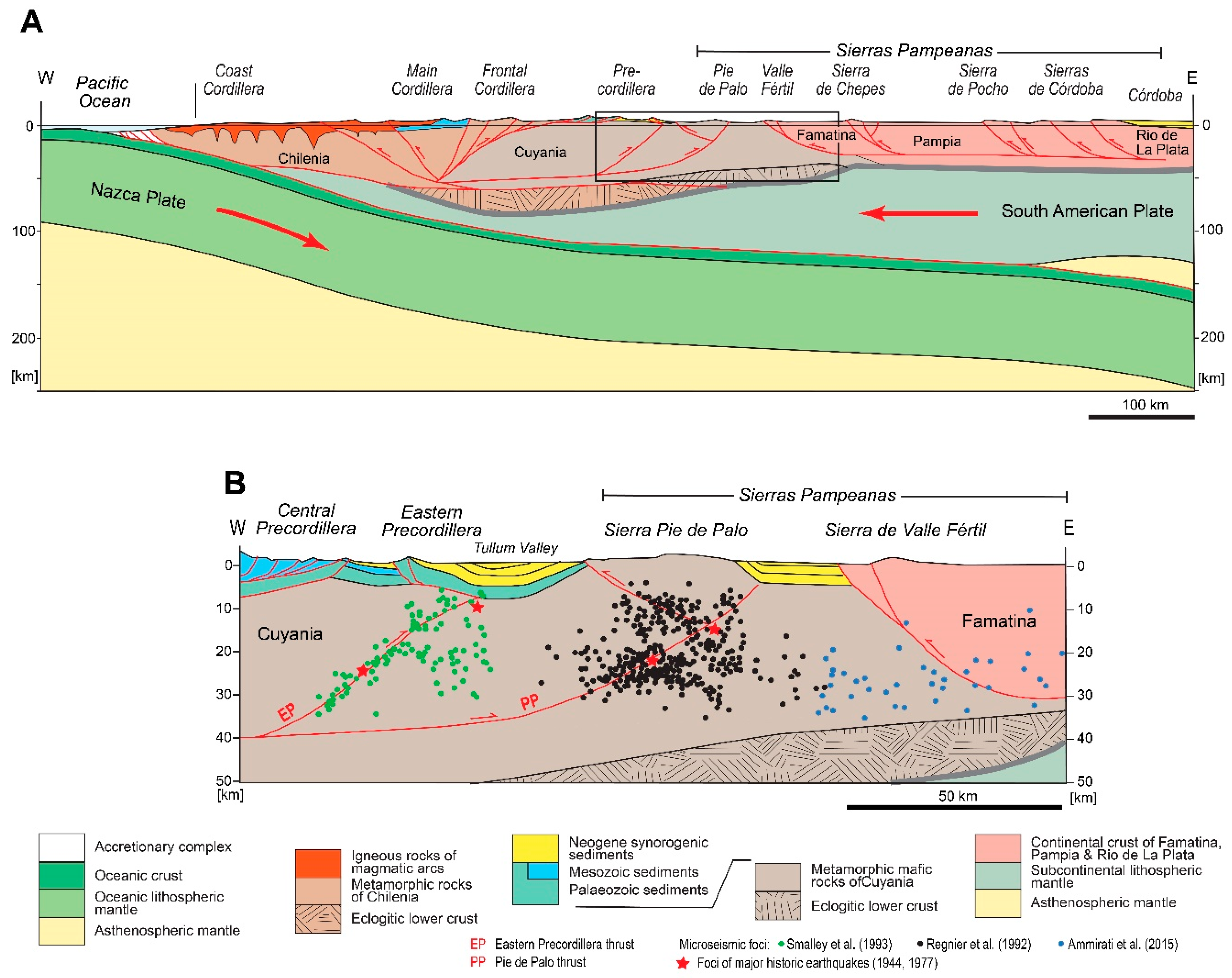
Within the Central Andes at this latitude, several terranes that were accreted to the Gondwana margin may be distinguished (see the cross-section along latitude 31° S shown in Figure 12A). From west to east they are:
- (1)
- The Chilenia terrane, built of gneisses, metasediments, metavolcanics and ultramafic lenses of Grenvillian age that are overprinted by Palaeozoic, Mesozoic and Cenozoic magmatic arcs. The latter modified the composition of the basement resulting in an average andesitic composition with lower bulk density and slow velocities in the lower crust [123].
- (2)
- The Cuyania terrane, which is a Laurentia-derived terrane with Grenvillian metamorphic rocks of predominantly mafic composition in the upper crust and a more felsic lower crust [123].
- (3)
- Three terranes are distinguished within the Sierras Pampeanas, all of which are Gondwana-derived: the Famatina terrane, (Protomargin of Gondwana), Pampia (Gondwana margin) and the Rio de La Plata craton [50]). All of these are made of Precambrian to Early Palaeozoic metamorphic rocks. The boundary between Famatina and Cuyania represents a crustal discontinuity, which controlled the nucleation of the Valle Fértil fault and associated basement uplift [50]). Early Palaeozoic mylonites that outcrop within a zone composed of Ordovician mafic and ultramafic rocks mark the boundary between Famatina and Pampia; Cenozoic faults were partially controlled by these Palaeozoic fabrics (Ramos et al., 2002). Similarly, the suture between Pampia and the Rio de La Plata craton, which contains ductile shear zones within Precambrian rocks, was reactivated by west-verging Cenozoic faults [50].
The cross-section of Figure 12A is based on [50,123,124,125,126] and complemented using the geological map of Chile [127]. Igneous rocks of Permian to Cenozoic magmatic arcs conceal the deep structure of the Coast Cordillera. Bivergent thrusting is found in the Main Cordillera. According to [124] Chilenia is delaminated by a wedge of Cuyania crust. The forceful intrusion of this wedge was responsible for the east-verging thrusting observed in the Frontal Cordillera and the (Western) Precordillera. The lower crust beneath the wedge is thought to be eclogitized [126]. Within the Sierras Pampeanas thrusting was predominantly west directed [50]. The thrust faults are interpreted to level off at a lower crustal level, probably within a low-velocity layer located at a depth of 25–30 km [125]. This low-velocity layer possible represents a thick mylonite zone, which separates the seismogenic upper crust from the aseismic lower crust.
The change from east verging to west-verging thrusting occurs within Cuyiana as shown in the detailed cross-section of Figure 12B which is based on [126]. The Pie de Palo thrust steps up from the base of the upper crust going east and bifurcates at a depth of 12 km into a west- and an east-verging thrust making the Sierra Pie de Palo a pop-up structure. The Eastern Precordillera thrust branches off the Pie de Palo thrust, steps up through the crust until the base of the Palaeozoic cover sequence, where it changes polarity and continues as a west-verging thrust to break surface on the western flank of the Eastern Precordillera. The recent activity of these thrusts is underlined by the earthquake foci straddling thrust faults within the Cuyania crust [128,129] and the adjacent upper crust of Famatina [125].
Reference [50] discuss the timing of the orogenic events in this transect. According to these authors, deformation and uplift of the Principal Cordillera took place between 20 and 8.6 Ma. Uplift and deformation of Frontal Cordillera occurred at 9 Ma, towards the end of the formation of the Principal Cordillera and was followed by thrusting in the Precordillera after 2.6 Ma. Andean deformation then migrated towards the east, towards the Sierras Pampeanas (op. cit.). Here, thrusting and uplift within the Sierras de Córdoba took place between 6 and 5.5 Ma (latest Miocene) and then progressed westward towards the Sierras de Chepes and Valle Fértil (op. cit.) and finally attained the Sierra de Pie de Palo at about 5 Ma [130]. Deformation continues to the present as indicated by the active thrust at the western limit of the Sierra de Valle Fértil [50], the ongoing uplift of 0.5–1 mm/a in the Sierra Pie de Palo [130] and the active thrust front of the Precordillera [50].
Arc magmatism in this transect propagated eastward; within the Sierras Pampeanas it preceded thrusting by about 4–2.6 my [50]. These authors conclude that weakening of the crust by magmatism was responsible for the initiation of Neogene thrusting and décollement. The structural position of individual thrust faults was seemingly controlled by pre-existing weaknesses as discussed above. Thus, reference [50] conclude that the initiation of thrusting was not controlled by horizontal stress variations but by thermal weakening associated with magmatism.
Active thrusting and uplift in the Central Andes at latitude 31° S occurs by bivergent thrusting in the (Eastern) Precordillera and the Sierras Pampeanas. At crustal scale, the upper crust of Cuyania is forced westward into the upper crust of Chilenia thereby thrusting the Precordillera to the east. Contemporaneously the upper crust of the Gondwana margin (Famatina, Pampia and Rio de La Plata) is detached at its base and thrust westward onto Cuyania. Thrusting within Cuyania is bivergent as well and responsible for the formation of the Sierra Pie de Palo. The eastern tip of the Andean chain and the adjacent Sierras Pampeanas are thus actively deforming in a thick-skinned manner involving a seismogenic upper crust and with thrust faults leveling off at the base of the upper crust. The thick-skinned deformation was trigered, resp. is now driven by the arrival, resp. subduction of the flat slab segment caused by the Juan Fernandez ridge within the Nazca plate. Reference [39] suspsect that shearing at the base of a flat-slab subduction may enhance coupling and thus generate additional compressive stresses within the upper plate, which then leads to intraplate shortening.
2.5. Northern Andes of Colombia
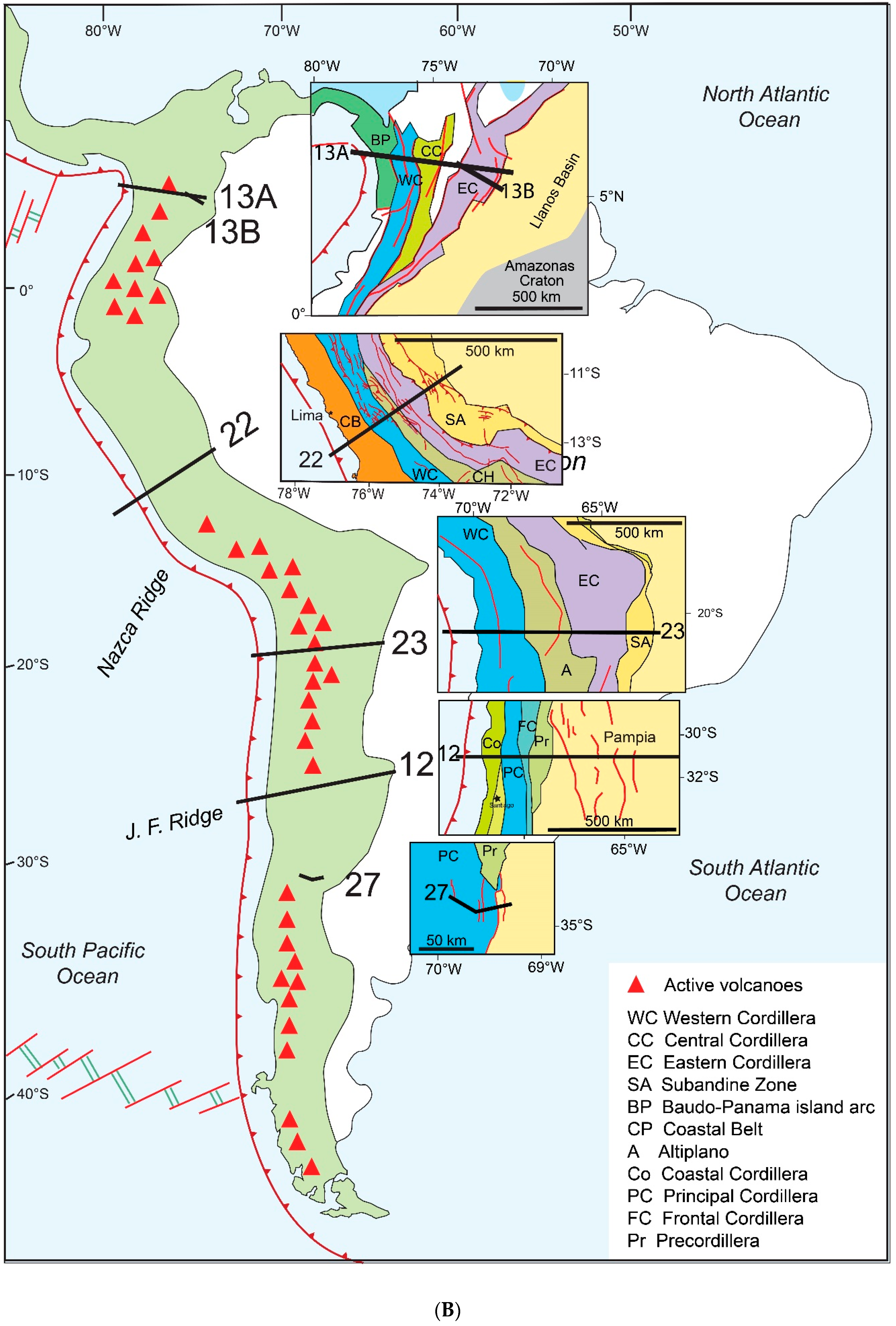
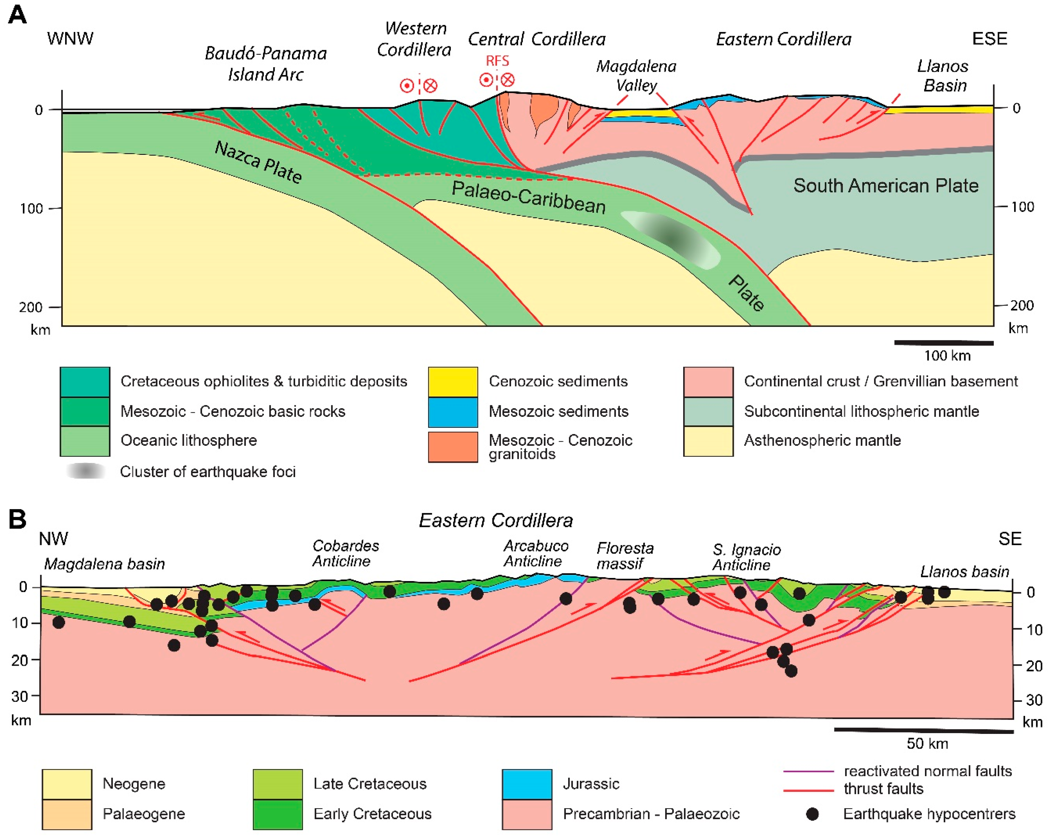
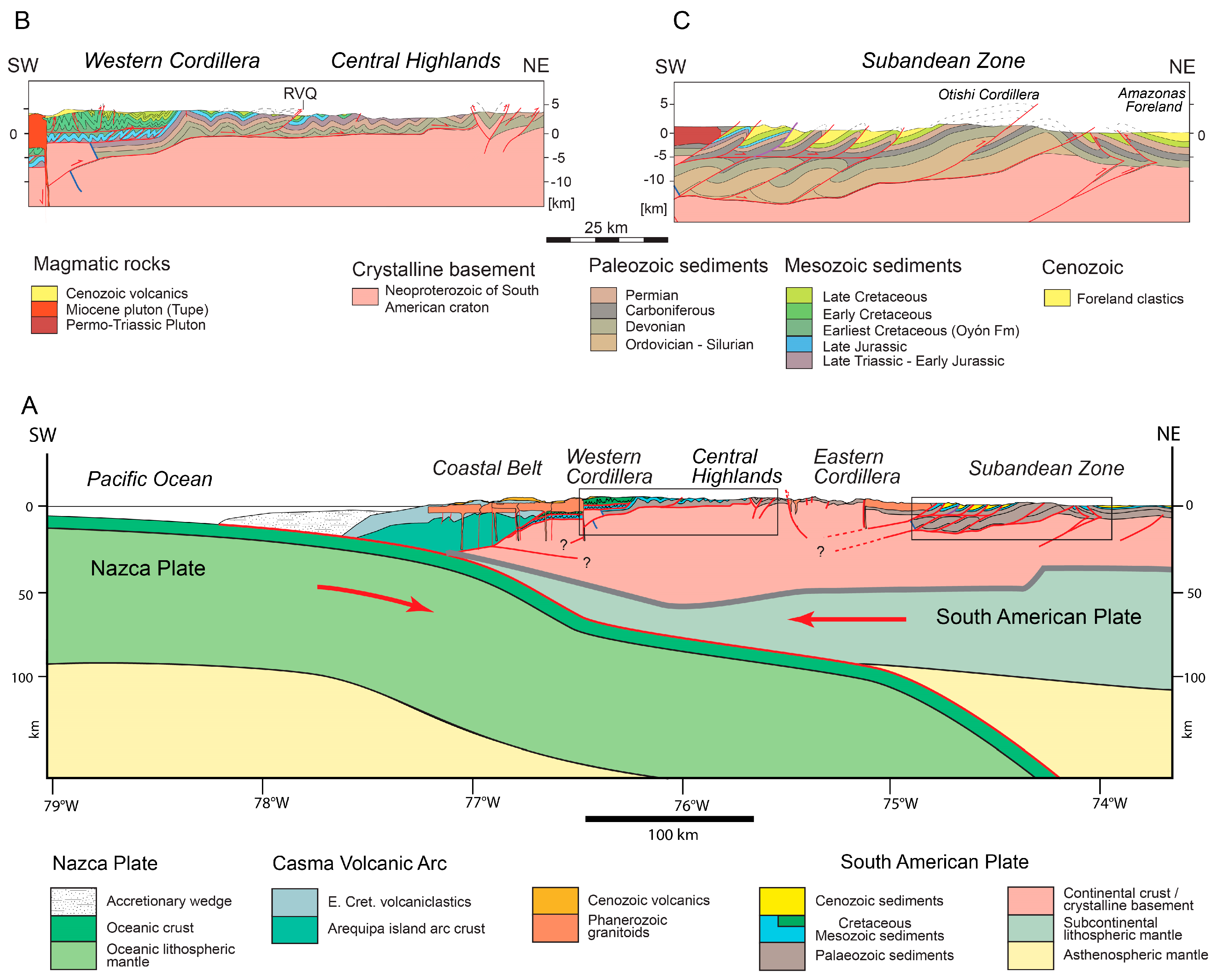
In the Northern Andes of Colombia subduction of the oceanic Nazca plate is accompanied by active shortening of the margin of the continental South American plate at considerable distance from the subduction trench. Three parallel running cordilleras, the Eastern, Central and Western Cordillera diverge and split towards the Caribbean, merge southward toward Ecuador, and display these contrasting tectonic styles. A cross-section spanning the entire orogen running at around 7° N is shown in Figure 13A; it is based on [131]. The Baudó-Panama island arc was formed at the western margin of the subducted Palaeo-Caribbean plate (see Figure 13A) and accreted to South America in mid Miocene to Pliocene times [131]. The Western Cordillera is made up of oceanic rocks (ophiolites and turbiditic sediments) that were accreted as blocks in Mesozoic to Palaeogene times [131]. The Central Cordillera is split into two domains by an important strike slip fault zone, the Romeral fault system. The western part contains oceanic material similar to the Western Cordillera and which represents obducted remnants of an oceanic plateau according to [132]. The eastern part on the other hand consists of continental crust of Grenvillian affinity and is intruded by Mesozoic and Cenozoic granitoids. Active volcanoes linked to the subduction of the Nazca Plate straddle along the crest of the Central Cordillera. The Romeral fault system has been active since Oligocene times along with reverse faults in the foothills of the cordillera. The Eastern Cordillera has Mesozoic sediments overlying continental crust with a Grenvillian type basement [133]. Bivergent thrusting reactivated Mesozoic synsedimentary normal faults and raised the top of the crystalline basement by up to 10 km.
The plate tectonic framework of the Colombian Andes is complex with east-verging and south-verging oceanic subductions [131]. In the transect considered here, two east-verging subductions may be recognized, an older one related to the subducted Palaeo-Caribbean plate, and a younger one connected with the subducting Nazca Plate according to [131] (see Figure 13A). The accretion of the Baudó-Panama island arc is associated with the older, shallow dipping subduction system. The western part of the three cordilleras, the area west of the Romeral fault system (also called “Occidente”) is of oceanic nature and was accreted to the western margin of the South American plate in Mesozoic and Cenozoic times (see [131] and references therein). The region east of the Romeral fault system (the “Oriente”) has a crystalline metamorphic basement of Grenvillian nature capped by Mesozoic and Cenozoic sediments, the Mesozoic part of which was affected by extensional tectonics since the Triassic [134]. Several phases of thrusting lead to the initial formation of the Eastern Cordillera between the Late Cretaceous and the lowermost Oligocene. The main phase of thrusting, however, started at 10.5 Ma, peaked in 6–3 Ma [135] and is still ongoing [131].
Considering the entire transect from the Pacific to the Llanos Basin, fault activity is recognized in the Subduction zone of the Nazca Plate, the strike- slip fault in the Western Cordillera, the Romeral fault zone, and the thrust faults in the eastern foothills of the Central Cordillera, as well as the thrust faults in the western and eastern foothills of the Eastern Cordillera ([131] and references therein). Thus, active contraction of the western South American margin is ongoing in a segment 400 km wide located 300 km to the east of the subduction trench. The associated shortening direction is more or less parallel to the E-W oriented relative motion direction between the Nazca and South American plates. Reference [136] argue that intraplate stresses are caused by the forces driving plate motions and that most of the stress is transmitted within the uppermost brittle crust (down to ~15–20 km depth). This is supported by the distribution of earthquake foci in the Andes of Colombia where most of the foci are at depths <30 km [131]. Deeper foci in the Eastern Cordillera north of 5° N are located within the mantle lithosphere of the subducting Palaeo-Caribbean plate according to these authors (see cluster Figure 13A); they also suspect that the lower crust and mantle lithosphere which lacks earthquake activity, deforms by ductile shearing.
The Eastern Cordillera has attracted the attention of researchers involved in fold-and-thrust tectonics related to hydrocarbon exploration. A key characteristic of this mountain belt is the reactivation of Mesozoic syn-sedimentary normal faults during Cenozoic contraction, a topic that is discussed in detail in [134,136,137]. Figure 13B is a detailed cross-section of the Eastern Cordillera of Colombia between 5.5° and 6.5° N based on [138]. The overall structure is a bivergent thrust belt in the core of which the top basement is uplifted 5 to 10 km relative to the foreland in the east and west. This uplift is caused by thrust faults, which are interpreted to flatten in the middle crust (at a depth of about 20 to 25 km). The displacements along these thrust faults are relatively small, no larger than 10 km. Thus it could be argued that they die out at depth owing to ductile shearing at higher temperatures. However, it has to be noted that some of these faults were originally formed as syn-sedimentary normal faults in Mesozoic times and were subsequently reactivated as thrust faults in the Cenozoic [134,138]. The Mesozoic activity is well documented in the oppositely dipping faults of the Cobardes Anticline (see Figure 13B), which delimit the occurrence of Jurassic strata. Similarly, the Cretaceous strata in the S. Ignacio Anticline are delimited by oppositely dipping faults, which are interpreted to be reactivated normal faults (op. cit.). In case of the Arcabuco Anticline, the asymmetric structure stems from an inverted tilted block bordered by a syn-sedimentary fault in the east. Taken together it emerges that the basement uplift, a feature that may be considered as a thick-skinned tectonic style, was largely controlled by the reactivation of Mesozoic normal faults in horizontal contraction. From fission-track and structural cross-section balancing [137] infer that the main uplift at 6–3 Ma caused increased erosion rates on the eastern flank of the Eastern Cordillera which triggered enhanced thrusting in this part of the cordillera.
Figure 13B also shows the distribution of the earthquake hypocenters from [139] according to [131,140]. It is interesting to note that the seismic activity indicated by the hypocenter distribution of earthquakes in Figure 13B suggests that the thrust faults in the foothills on either side of the Eastern Cordillera are still active while the core of the cordillera is uplifted somewhat more passively. The Eastern Cordillera thus represents an archetypal inverted basin presently undergoing thick-skinned tectonics.
2.6. Central Alps of Switzerland
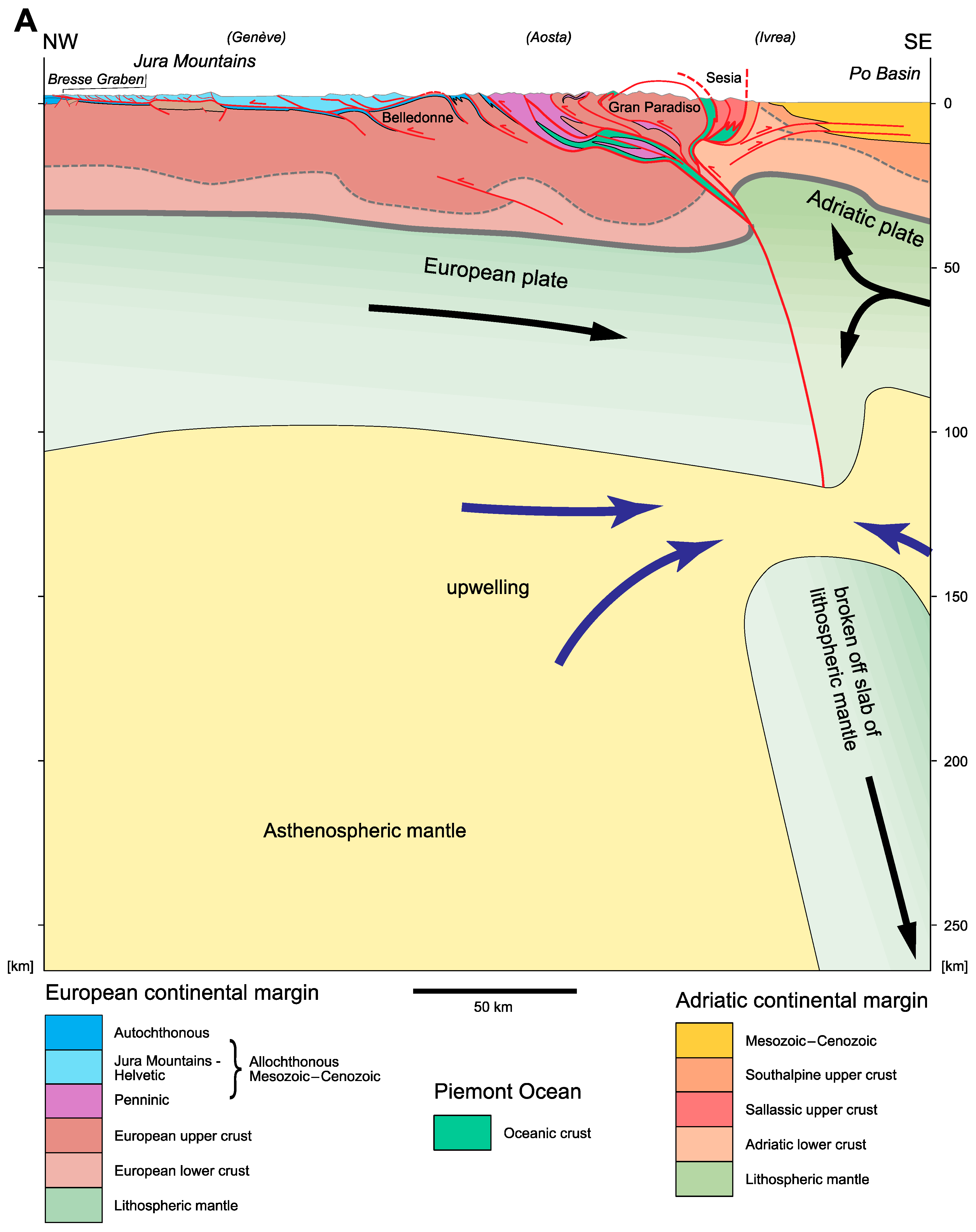
The Alps are a collisional orogen that formed as the Piemont Ocean that had formed in Jurassic and Cretaceous times between the European and the Adriatic margin was subducted and the two margins collided. High-pressure assemblages of Cretaceous age in the Eastern Alps and Palaeogene age in the Central and Western Alps [141] mark the onset of the orogeny. The ensuing nappe stacking lasted into Neogene times (see [142] for a compilation of orogenic time tables). The Central Alps of Switzerland can be envisaged as an orogen in a waning stage of activity in continent-continent collision.
The cross-section shown in Figure 14 comprises the following major units from North to South:
- (1)
- The stable foreland exposed in the basement uplift of the Black Forest.
- (2)
- The Jura Mountains, a slightly allochthonous Mesozoic sequence piled up by imbricate thrusting. A Permo-Carboniferous graben is present within the underlying crystalline basement.
- (3)
- The Molasse Basin, a foreland basin which was displaced piggy back with the underlying Mesozoic sequence that connects with the Jura Mountains.
- (4)
- The Alpine nappe stack that include the Helvetic and Penninic nappe system. The uppermost, Austroalpine nappe system has been eroded altogether in this transect. Helvetic and Penninic units are made of crystalline basement units and of highly allochthonous Mesozoic cover units. Aar, Gotthard and Verampio pertain to the proximal (Helvetic) European margin, Antigorio and Maggio to the distal (Penninic) part.
- (5)
- The Southalpine nappe stack with a lower crustal section (Ivrea) and an upper crustal section (Strona-Ceneri) with Mesozoic and Cenozoic cover. The Po Basin corresponds to the Cenozoic cover.
A temperature-dominated metamorphic overprint affected the Alpine nappe stack, grading from a diagenetic stage at the southern end of the Molasse Basin and reaching amphibolite facies grade just north of the Insubric Fault [141]. Alpine overprint was less to south of this fault, grading from anchizonal to diagenetic grade.
The cross-section of Figure 14 is based on reflection seismic data of NRP20 (Central and Southern traverse; [143,144]), teleseismic tomography and controlled-source seismology [145,146,147]. Earthquake loci are from the SED catalogue (Swiss Seismological Service) and are projected from a swath of 25 km width onto the cross-section (see [148]).
Cenozoic Alpine thrusting was north-verging to the north of the Insubric Fault and south-verging to the south of it. The basal thrust faults of the Helvetic nappes are folded into an open antiform that is cored by the Aar massif owing to the late updoming of this basement block. North of the Insubric Fault the thrust faults within the crystalline basement are folded into an antiform. This antiform developed during vertical escape of the units along the Insubric Fault. The thrust faults in the Southalpine nappe system cut across the entire crust and were responsible for exhuming the lower crust of the Ivrea Zone, which barely reaches the surface in this transect. The boundary between lower and upper crust was chosen somewhat arbitrary as P-wave velocity of 6.5 km/s. It is interesting to note that while the Moho is a smooth surface, the boundary between upper and lower crust has a wavy form north of the Insubric Fault; it defines an antiform just north the this fault which underlines the antiform defined by the folded thrust faults. South of the Insubric Fault the lower crust rises stepwise towards the surface by thrusting. The smooth shape of the Moho signifies that the lowermost crust is strong and remained attached to the upper mantle, while its upper part was apparently weaker and thus folded by ductile creep. This point will be discussed again in Section 3.1.7 (Western and Eastern Alps).
The recent seismicity and the vertical uplift clearly show that the Central Alps are still actively deforming. Uplift data shown in Figure 14 stem from high precision leveling and from Global Navigation Satellite Systems. High precision leveling are from two independent networks: the Swiss network CHTRF [149] with a reference point in the Black Forest and the Italian network ITRF [150] with a reference point in Genova. The discrepancy in uplift rates between the two near the Insubric Fault remains to be cleared (see compilation map in [142]). The GPS data of GNSS are taken from [151]. The uplift rates are relative to stable Europe, which may explain the discrepancy to the CHTRF data. In any case, all three data sets show that the Central Alps are being uplifted by roughly 1 mm/a relative to the foreland in the north and south with a maximum north of the Insubric Fault. The uplift maxima in eastern and western Switzerland are higher (around 1.5 mm/a). It is interesting to note that Zircon and Apatite fission track data (see compilation by [152]) show a similar regional distribution of maximum exhumation rates suggesting that the present day pattern has been active at least since 5 Ma [142].
Earthquake foci within the Alps are at depths less than 10 to 15 km, whereas in the foreland they are distributed throughout the entire crust. Earthquake mechanisms suggest a predominantly strike-slip/thrust fault regime [153] in the northern part of the Alps (north of Gotthard in Figure 14) and a normal-fault regime in the south. Within the Molasse Basin focal mechanisms indicate a strike-slip/normal-faulting stress regime, and farther to the north it is strike-slip (op. cit.). Stress orientations derived from fault-plane solutions indicate a rotation of the principal axes from the foreland into the orogen. Reference [153] explain this change by the effect of the crustal root beneath the Alps, which induces a component of gravity spreading in the uppermost part of the orogen. In fact, numerical modeling also show that such an extension parallel to the overall contraction develops in the core of model orogens as a consequence of gravitational spreading [44,61].
The pattern of the uplift rates might be caused by ongoing updoming of the Aar massif in conjunction with motion along the S-dipping thrust fault beneath this basement block. The S-dipping thrust connects upward with thrust faults within the southernmost Molasse Basin (the so-called Subalpine Molasse) and northward with the décollement thrust at the base of the Jura Mountains. These thrust faults represent the latest phase of thrusting on the north side of the Alps, i.e., Late Miocene in the Molasse Basin and Pliocene in the Jura Mountains (see [142] and references therein). In fact, [154] report tilted gravels from north of the Jura Mountains that are 3 Ma old and thus testify to a Plio-Pleistocene age of deformation. It thus follows that the ongoing vertical uplift and seismicity may well represent a latest stage of Alpine deformation. Similarly, on the Southside of the Alps, post-Messinian sediments in the Po Basin rest unconformable on older strata [155,156] and indicate a Plio-Pleistocene phase of Alpine contraction. Summing up it is concluded that the Alps represent a collision orogen in the waning stage of its formation.
Considering uplift rates and the contrasting stress regimes derived from fault plane solutions within the Alps it might be argued that the seismogenic deformation in the north (Aar massif and area to the north of it) is related to updoming in the hanging wall of the crustal thrust fault, while to the south of the Aar massif it is caused by the buoyant rise of the crustal root and concomitant gravity spreading. The distribution of earthquakes in the lower crust of the foreland basin and the Jura Mountains is explained by the effect of rollback of the European slab beneath the Alps [157]. According to these authors fault plane solutions are in agreement with bending of the European slab combined with a buoyancy force stemming from the subducted lower crust.
3. Ancient Mountain Belts
To differentiate between thick-skinned and thin-skinned tectonics insight into the internal structure of mountain belts is needed. Although significant erosion may have removed much of this information, the deep cores of orogens are accessible to observation in ancient mountain belts that formed in Palaeozoic to Cenozoic times. Modern (Cenozoic) representatives within ancient mountain belts possess a more juvenile topography. This has the advantage that in many instances structures indicating tectonic styles are directly observable on valley flanks. In the following a selection of classic examples from the Americas, Europe, Africa and Asia are presented. They are grouped according to the large-scale setting, starting with collision and subduction related orogens, followed by particular structureal settings (passive margins of particularly width, basin inversion and classic thin-skinned tectonics).
3.1. Continent-Continent Collision
3.1.1. Caledonides
The Caledonian mountain belt in Europe spans the area of Scandinavia, the British Islands and finds its continuation in Greenland and in the Appalachians. Here we concentrate on two cross-sections that have been studied in much detail in the past, one in Scotland and one in southern Norway.
Reference [158] distinguish three major tectonic units in the Scottish Caledonides. They are, from bottom to top:
Foreland, built of Lewisian crystalline basement, pertaining to Laurentia and covered by Proterozoic-Palaeozoic sediments.
Moine Thrust Zone, in which slices of Lewisian basement and its cover rocks are stacked to a nappe pile above a sole thrust.
Moine nappe complex, which consists largely of a metamorphosed siliciclastic sequence (the Moine series), deposited on the eastern sector of Laurentia.
The cross-section displayed in Figure 15A, based on [8,158], shows the architecture of the Scottish Caledonides in the NW Highlands. The Sole thrust of the Moine Thrust Zone is located in Fucoid beds of the Cambrian An t-Sron Formation in the traverse of Figure 15A [8,159]. Further east it eventually steps down into the Lewisian basement. The Cambro-Ordovician sediments above the Sole thrust are affected by numerous imbricate thrusts forming duplexes. Very thin slivers of Lewisian basement were carried along the Ben More and Glencoul thrusts, and relatively tight ramp anticlines developed where these thrust faults ramped up from the Lewisian basement through the Cambrian formations. The stacking of Lewisian basement by the Sole thrust and the Ben More and Glencoul thrusts gave rise to an antiformal stack, referred to as Assynt culmination in the local literature. Individual thrust faults are sharp faults with indications of brittle deformation [159]. They are taken to have formed at relatively high crustal levels and temperatures not exceeding 275 °C.
The metasediments of the Moine nappe complex stem from sandstone and siltstone protoliths of Neoproterozoic age and were most likely deposited in a Grenvillian (ca. 1000 Ma) foreland basin [158]. The nappe complex contains lenses of “Lewisianoid” gneisses and Caledonian plutonites. Several ductile thrust faults dismember the Moine nappe complex. The Achness thrust sheet is a coherent block within the nappe complex and is internally folded by large-scale folds (Figure 15A). A mylonite zone that indicates ductile deformation at higher temperatures accompanies the Moine thrust itself (it is this locality where Lapworth coined the term “mylonite” in 1885). All in all the degree of metamorphism in the Moine nappe complex is higher than the one in the underlying Moine Thrust Zone. It seems therefore that the Moine thrust carried hot, mid-crustal rocks onto cooler rocks of the future Moine Thrust Zone. In the course of subsequent propagation of thrusting downward, the Moine thrust was passively deformed and arched above the Assynt culmination.
The Scandian orogeny includes the motion along the Moine thrust and the development of a ductile mylonite zone in the middle Silurian (435–430 Ma; [158,159] and references therein). The Moine Thrust Zone formed slightly later in the late Silurian (431–419 Ma). As discussed by [8], the Loch Ailsh intrusion (430 Ma) cuts the Glen Oykel thrust, but is itself cut by the Ben More thrust below, and the Moine thrust above in a late brittle phase of its activity (see Figure 15A).
Regarding the tectonic style, the Moine nappe complex involved thrusting at mid-crustal level involving high-grade metasediments, which suggests a thick-skinned style. A thick-skinned style is in effect confirmed by seismic profiling of MOIST [160] where the upper crust contains several reflections, which are interpreted as thrust faults that sole into a horizontal reflection band at a depth of around 20 km. However it is not clear yet if these imbricate thrusts are in the hanging wall of the Moine thrust—in which case the Moine thrust would root at around 20 km depth—or if these imbricate thrusts are in the footwall of the Moine thrust. The Moine Thrust Zone on the other hand clearly displays thin-skinned style tectonics with duplexes consisting of sedimentary rocks and only thin slivers of crystalline basement being involved by thrusting. It represents an archetype of basement-involved thin-skinned tectonics.
In the Scandinavian Caledonides of southern Norway four tectono-stratigraphic units are distinguished (see [161] and references therein). They are from bottom to top:
Autochthon/Parautochthon: Precambrian crystalline basement rocks pertaining to Baltica, with remnants of autochthonous cover.
Lower Allochthon: detached sediments of Vendian to Early Ordovician age, originally deposited on Baltica.
Middle Allochthon: Precambrian crystalline basement rocks pertaining to Baltica, and associated cover sequences.
Upper Allochthon: ophiolite complexes pertaining to the Iapetus Ocean, with island arc and marginal basin sequences.
The structure of the Scandinavian Caledonides is illustrated in the cross-section of Figure 15B, which is based on [161,162,163]. The Lower and Middle Allochthon are relatively flat lying thrust sheets (see Figure 15B) that were piled up during the Scandian orogeny in mid Silurian to Early Devonian times [161]. In the traverse of Figure 15B, the Lower Allochthon consists of two duplex complexes, the Aurdal and Synnfjell duplexes (see inset in Figure 15B, and [162]). The Jotun Complex of the Middle Allochthon is a large-sized basement block that overrode cover rocks of the Lower Allochthon. Whereas the Jotun basement block is internally hardly affected by Scandian deformation, a strongly sheared and mylonitized zone is found at its base, which grades downward into highly sheared metasediments and basement slices derived from the underlying Lower Allochthon [161]. The Upper Allochthon outcrops on top of the Middle Allochthon in the traverse of Figure 15B. But elsewhere it lies directly on Lower Allochthon or even Autochthon/Parautochthon. Its internal structure reflects mainly the Scandian orogeny when it was dismembered fand obducted, and, to a lesser degree, the intraoceanic history of the Iapetus Ocean ([161] and references therein).
Late to post-orogenic normal shear zones cut the nappe structure and bear witness to important crustal stretching [161,163]. The Lærdal-Gjende fault connects at depth with the Hardangerfjord shear zone and the Nordfjord-Sogn detachment is thought to level off completely at depth. An additional oppositely dipping normal shear zone in the lower crust is responsible for the step in the crust/mantle boundary observed by seismic reflection profiling [164]. Thus, the entire crustal section appears to be thinned towards the WNW. Reference [163] explain this thinning by the effect of the Scandian orogeny: The Caledonian crust was subducted and thus hot and able to viscously flow after the change from convergence to divergence. The Baltic crust on the other hand was cooler and stronger and thus not affected by divergence. The change from convergence to divergence occurred shortly before 400 Ma [165] and resulted in the formation of a number of Devonian basins.
In the transect of Figure 15A, the Scandinavian Caledonides exhibit a thin-skinned tectonic style in the Lower Allochthon with the Aurdal and Synnfjell duplexes, a thin-skinned basement-involved style in the Valdres thrust sheet (Middle Allochthon) and a more thick-skinned style in the Jotun complex. The tectonic style of the obducted Upper Allochthon is more difficult to assess. This complex contains slices of various crustal levels and oceanic fragments. The highly extended crust was thin to begin with, such that upon contraction very small pieces were piled up that now form a tectonic mélange. The post-orogenic extensional phase was clearly thick-skinned as it affected even the lithospheric mantle.
3.1.2. Variscides
The Variscan chain running across Europe and connecting to the Appalachians developed from a complex palaeogeographic pattern characterized by two oceans located between Laurentia-Baltica and Gondwana: the Rhenohercynian Ocean (a remnant of the Rheic Ocean) in the north, and Palaeothethys in the south [166,167]. The Rheic Ocean opened in the Early Ordovician, Palaeotethys in the Devonian. Microcontinents, or ribbon continents, formed in the intraoceanic area between these two basins [167]. In the traverse of the central European Variscan chain considered here, they include the Saxothuringian, Barrandian and Moldanubian zones [168].
In Devonian and Early Carboniferous times the ribbon continents were amalgamated and in Late Carboniferous times Laurentia-Baltica and Gondwana collided [167]. Ribbon continent amalgamation and continent-continent collision were accompanied by magmatic activity. In the Moldanubian zone granites intruded within a relatively short time interval between 340 and 332 Ma [169] coeval with thrusting. The melts of this short episodic magmatism are explained by mantle upwelling into the crust. Post-Variscan, i.e., Permian plutons intruded farther south, on the Gondwana margin [142]. Reference [170] discuss Permian and Triassic granites that occur throughout the Alps, which are in part associated with Permian graben structures. They explain this magmatism by a Permian thermal event possibly related to lithospheric thinning and associated magmatic underplating.
As shown by [171], the European Variscides are a curved belt with a bivergent nappe structure. Figure 16 shows a cross-section through the Variscides of Germany, which is based on [171] and amended by [172,173]. Thrusting was NW-directed northwest of the Central Bohemian shear zone and SE-directed to the southeast of it. The Central Bohemian shear zone is a major strike-slip shear zone in the core of the orogen, which according to [171] may be traced all along the Variscan chain from Bohemia to Iberia.
In the core of the German Variscides, crystalline basement blocks of the Modanubian, Barrandian and Saxothuringian zones, which pertain to the accreted ribbon continents, are involved in thrusting that reaches down to the base of the crust and into the lithospheric mantle. Interestingly, where these thrust faults reach the crust/mantle boundary, refraction and reflection seismics obtained in the framework of the European Geotraverse EGT [174] image a through going Moho (labeled Seismic Moho in Figure 16). Reference [172] pointed out that the lower crust of Baltica and Gondwana could well extend into the lithospheric mantle. If these rocks were eclogitized they would seismically be indistinguishable from the surrounding mantle rocks. A possible trace of a Baltic and Gondwana Moho is indicated in Figure 16 and labeled as Petrologic Moho and could extend much deeper into the mantle than shown in Figure 16. In the more shallow parts, units of oceanic nature separate the ribbon continents. They are obducted pieces of the oceanic domain between the Rhenohercynian Ocean and Palaeotethys. All in all the core of the Variscan chain clearly displays a thick-skinned tectonic style.
In the northwestern part of the cross-section, in the Rheno-Hercynic zone (the Rheinisches Schiefergebirge), the Palaeozoic cover was shortened and piled up to an imbricate stack of thrust sheets in a thin-skinned style. The thrust sheets are underlain by a relatively thick décollement layer, a tectonic mélange containing slices of MOR-type basalts and neritic clastics and carbonates of Ordovician–Early Carboniferous age [168]. A 300 km long slab of continental crust underlies the Rheno-Hercynic zone. Reference [175] argue that the Variscan orogeny was a “hot” orogen owing to repeated episodes of magmatism. These high temperatures weakened the crust, squeezed low-velocity metamorphic rocks towards the foreland and caused the spreading out of the deeper parts of the crust [175]. Thus, the crustal root disappeared and the continental crust attained a relatively low thickness of 30–35 km.
3.1.3. Central Australia
The Alice Springs Orogen in central Australia is an example of a collisional intracratonic mountain belt that displays both a thick-skinned and a thin-skinned tectonic style. The orogeny peaked in Late Carboniferous times [176]. Although local relief is nearly absent the area shows important positive and negative gravity anomalies [16], which point to important changes in crustal architecture. Two major crystalline blocks, Arunta in the north, Musgrave in the south, consist of Mesoproterozoic rocks that were affected by faulting in the latest Proterozoic and middle to late Palaeozoic. Three basins accompany the two blocks, from north to south, the Ngalia, Amadeus and Officer Basins [176]. These basins were initiated at about 800 Ma and are interpreted to have formed in response to thermal subsidence ([176] and references therein).
The cross-section displayed in Figure 17 covers the Arunta block and the Amadeus Basin. It is based on structural analyses [16] and deep seismic profiling [176]. Several thrusts reach deep into the crust and brought lower crustal material up to the surface. Teyssier (1985) considered that the thrust faults level off at depth. In contrast, [176] argue that the Redbank Fault Zone reaches even deeper down and offsets the crust/mantle boundary. The sequence of crustal thrusting according to [16] proceeded from north to south and structurally down. The plunging hanging-wall anticline of the Redbank Fault Zone is explained by the formation of an antiformal stack in the footwall of this fault.
As clearly shown in the cross-section, the sedimentary fill of the Amadeus Basin was detached from its crystalline basement, thrust to the south and internally shortened by folding and thrusting. Late Proterozoic evaporites of the Bitter Springs Formation acted as décollement layer [16]. The basal thrust of this detached cover is gently warped by the underlying basement nappes of the Arunta block. The kinematic evolution after [16] implied first thin-skinned tectonics in the sedimentary cover as well as thick-skinned tectonics in the crystalline basement. The basal detachment of the cover units thereby acted as roof thrust of the basement imbricates. In a latest event, the Arltunga nappe complex was shortened further and slightly updomed, possibly by motion along the Redbank Fault Zone and the imbricate thrusts in its footwall. The basal thrust fault of the cover sequence was by then inactive and consequently also updomed above the Arltunga nappe complex.
3.1.4. Eastern Australia
The New England thrust belt and adjacent basins in eastern Australia have a complex subduction related Palaeozoic history, which is summarized in [177]. The discussion here concentrates on the southern New England thrust belt, which sits on an accretionary wedge with sediments ranging in age from the Silurian to the Carboniferous. The accretionary complex was built by west-directed subduction. The Tamworth belt to the west of the New England thrust belt contains Early Devonian to Early Permian arc volcanics interlayered with marine sediments. The latter were deposited in successively more shallow-marine conditions towards the west, indicating an east-facing arc flank. Volcanism reached a climax in the Early Carboniferous (340–330 Ma; [177]). The adjoining Gunnedah Basin (part of the larger Sidney Basin) was initially extensional [178] and was filled by Permian volcanic rocks which grade upward into fluvio-deltaic and continental clastics. The clastic basin fill is at least partly derived from the New England thrust belt [177]. West-directed thrusting during the Hunter-Bowen orogeny at 265–256 Ma (Mid–Late Permian) affected the Tamworth belt and the Gunnedah Basin. Contractional deformation progressed towards the west [178]. Oroclinal bending in the Late Permian (the so-called “dispersal event”) was responsible for the rotation of entire blocks of the New England thrust belt by as much as 90°.
The cross-section displayed in Figure 18 was compiled from deep seismic profiling data published and interpreted by [178,179,180,181]. The main cross-section is depth converted with an average crustal velocity of 6 km/s. As a consequence, the dips in the more shallow parts are too steep. The insets shown above the main section are based on [180] and are depth-converted assuming an average velocity of 4 km/s. The New England thrust belt is bound in the west by a major west-dipping thrust fault, the Peel Fault. According to [180], lower crustal rocks and a serpentinite mélange were brought from depth to the surface along the Peel Fault (see inset in Figure 18). West-dipping reflections within the New England thrust belt are interpreted to stem from thrust faults inside the accretionary complex. The Tamworth belt on the other hand was thrust to the west along the Kelvin Fault and the Mooki Fault (see inset in Figure 18), making the New England thrust belt doubly verging.
The Peel Fault cuts across the entire crust and probably extends into the lithospheric mantle and thus clearly represents a thick-skinned tectonic style. The fact that the crust-mantle boundary does not show an offset may be due to post-orogenic re-equilibrations, either by Cenozoic magmatic underplating [180] or by eclogitization of subducted crust. Refraction seismics along a N-S traverse through the New England thrust belt by [182] indicate relatively low seismic velocities in the crust, increasing from 5.5–6 km/s near the surface to 6.45 km/s near the crust/mantle boundary, and also anomalously low velocities of 7.7 km/s in the uppermost mantle. Delamination and underplating related to the formation of the Tasman Sea basin is thought to be responsible for the observed low velocities in the New England thrust belt. The architecture of this orogen with east-verging thrust faults affecting the very thick accretionary wedge sediments has likely been substantially modified by the basin forming process and is therefore difficult to interpret in terms of thick-skinned or thin-skinned tectonics. Given that only sediments are involved, an extremely thick thin-skinned tectonic style could be invoked. For the Tamworth belt, west-directed thrusting clearly is of thin-skinned tectonic style.
3.1.5. Apennine
The Apennine thrust belt is the backbone of the Italian Peninsula. The cross-section of the Northern Apennine at around 43° N shown in Figure 19A was chosen because of the availability of the geophysical data of the CROP 03 project [183] on the crustal structure, and mantle structure derived from high-resolution earthquake tomography [184].
Although the Apennine thrust belt formed in Miocene times, an ancestral Alpine nappe pile is present along the western coast of the Peninsula (see Figure 19A). This thrust belt was the product of the collision of the Corsica-Sardinia block (European margin) with the Adriatic microplate [185], and according to [186] related to an east-dipping Alpine subduction. In the Apennine thrust belt, Mesozoic sediments of the passive Adriatic margin and Cenozoic foreland deposits were involved in east-directed thrusting towards the Adriatic foreland contemporaneously to extension in the hinterland. This extension is indicated by several east-dipping normal faults cutting across an ancestral Alpine nappe pile between Corsica and the western (Tuscan) coast of the Italian Peninsula (see Figure 19A). The extension in the hinterland as well as the contraction in the Apennine thrust belt migrated towards the east in time [187] and are associated with a west-dipping Apennine subduction (see Figure 19A). Reference [186] suspect that subduction flip took place in the Paleocene to Eocene and possibly was diachronous along strike. Reference [188] suggest that the eastward migration of extension and contraction was associated with slab retreat of the west-directed Apennine subduction, which created a back-arc basin that is recorded by the extension and magmatism in the Tyrrhenian Sea and the western Italian Peninsula, and was responsible for the observed lithospheric upwelling.
The structure of the Apennine nappe pile has been addressed using a thin-skinned style, a thick-skinned style or an inversion style (see discussion in [39,185]). The geometry displayed in Figure 19B is compiled from [185,189] who included the deep structure for the first time and interpreted the structural style in terms of inversion tectonics. Several thrust faults repeat the Mesozoic-Cenozoic strata and reach deep down into the crystalline basement. Besides, Mesozoic and Cenozoic normal faults are discerned. The Mesozoic normal faults are syn-sedimentary faults and most of them were reactivated in compression (e.g., in the Adriatic Ridge or the Sibillini Mountains thrust in Figure 19B). Apart the reactivated normal faults, the involvement of basement is thought to have occurred by shallow dipping thrust faulting. Displacement along these faults is minor, with the exception of the Sibillini Mountains thrust, which reaches down into the lithospheric mantle and offsets the crust/mantle boundary. Reference [185] estimate the total shortening of the Apennine thrust belt to be about 7.7 km only, much less than the 50 km estimate from a thin-skinned style by [190]. Reference [39] provides an in-depth discussion on the evolution of thought on the structural style and the associated shortening of the Apennines.
3.1.6. Himalaya-Tibet Orogen
The Himalaya-Tibet orogen is the result of Mesozoic accretion of terranes now present in the Tibetan Plateau, followed by the collision between India and Eurasia in the Cenozoic [68,83]. The collision, which started at 55 Ma and is still ongoing, produced two mountain belts adjacent to the Tibetan Plateau, the Kunlun Mountains at its northern rim and the Himalayas at its contact with the Indian plate in the south. The high elevation of the Tibetan Plateau, exceeding 4000 m, has been in the spotlight of research over decades. Reference [83] provide an in depth discussion of the issue and will be summarized briefly. To this purpose, a cross-section at plate scale along a traverse between 89° and 90.5° E was drawn (Figure 20), based on that paper complemented by [72,191].
The Himalaya thrust belt, discussed in some detail in Section 2.1, is 2500 km wide and undergoes important changes along strike (see e.g., [69]). The traverse chosen here is located in the eastern Himalaya at ~90° E and follows the INDEPTH deep reflection profiles [81].
The Main Himalaya thrust extends northward beneath the Tibetan Plateau where it may be correlated with the top contact of the inserted lower crustal slab (Figure 20). The cross-section shows the anomalous thickness of the crust beneath the Tibetan Plateau, which is responsible for the high elevation. The thickness of the crust is explained by Indian lower crust that inserted at the base of the Tibetan Plateau [83]. The length of this slab (~650 km) balances the shortening of the detached upper crust now present in the Himalayan thrust belt. As discussed by [68], it is however also conceivable that part (or all?) of the Indian lower crust was eclogitized and subducted into the mantle.
Within the Tibetan Plateau, the Banggong and Jinsha oceanic sutures delimit the terranes that were accreted in Mesozoic times. In the Kunlun and Altun Mountains, namely in the Quilian Shan thrust belt, crustal scale thrust faults suggest a thick-skinned tectonic style. Besides thrusting large-scale strike-slip faults accompanied this shortening (Kunlun and Altyn Tagh strike-slip faults in Figure 20).
Two slabs of lithospheric mantle plunge beneath the Tibetan Plateau. The northern one is ~200 km long and balances the crustal shortening in the Quilian Shan thrust belt. The one in the south is far too short to balance the deformed margin of the Indian plate now present in the Himalayan thrust belt. As discussed in [83], the leading edge of the Indian lithospheric mantle slab broke off at about 40 Ma and foundered into the mantle. The offset between the broken off slab and the tip of the plunging Indian slab of ~500 km corresponds to the post-40 Ma northward motion of the Indian plate, which is compensated by shortening within the Himalayan thrust belt. This number compares roughly with the ~400 km of shortening estimated for traverses in eastern Nepal [83].
The collision of the Indian plate with Eurasia, respectively the Tibetan Plateau was accompanied by delamination of the tip of the Indian plate. The lithospheric mantle was subducted (including slab break-off), the lower crust was inserted beneath the Tibetan Plateau, and/or subducted, while the upper crust was stripped off and accreted at the front of the Tibetan Plateau. Frontal accretion of this upper crust had a major décollement, the Main Himalayan thrust, which stepped up southward from the base of the upper crust at the contact to the Lhasa terrane and broke surface as Main Frontal thrust (see Figure 20) in the latest stage.
A feature of interest is the horizontal sheet of ophiolites of the Indus-Yarlung suture at a depth of 30 km beneath the surface outcrops of this suture (see Figure 20). INDEPTH data by [191] reveal the presence of a high-velocity layer at this position. The connection of the surface exposures to the horizontal layer at depth is speculative. Nevertheless the presence of a buried ophiolite points to a certain wedging of Lhasa upper crust into accreted and stacked Indian upper crust.
All in all, the Himalyan-Tibetan orogen stands as example of crustal and lithosphere scale thick-skinned tectonics. During the Cenozoic the amalgamated terranes of the Tibetan Plateau acted as upper plate units and were only slightly deformed, whereas the lower plates, India and Eurasia, were strongly deformed in the course of collision.
3.1.7. Western and Eastern Alps
The allochthonous nature of sedimentary units in the Alps has been recognized in the 19th century already and soon initiated a discussion on the question about the crystalline substratum of the detached sediments. Thus for Alpine geologists the involvement of crystalline basement in nappe tectonics was never questioned. The thick- and thin-skinned involvement of crystalline basement in Alpine nappe tectonics has been discussed recently by [1,38,120,192,193] and will thus be touched briefly only here. The two examples presented below, the Western and Eastern Alps, were chosen for their particular aspects regarding tectonic style.
The cross-section of the Western Alps displayed in Figure 21A is based on the geological interpretation of the seismic lines of ECORS/CROP [194,195,196,197,198], structural work by [199], and teleseismic studies carried out by [145,146,147]. Earthquake tomography by [200] revealed the lithosphere structure. The following observations may be extracted from this compilation:
- (1)
- The allochthonous Mesozoic–Cenozoic strata of the Helvetic nappes and the Jura Mountains were detached along Triassic evaporites mainly and transported to the NW. They now form a wedge that was thickened internally. The basal thrust was severely deformed in the rear part by the updoming of the external massifs (e.g., Belledonne).
- (2)
- In the Penninic nappes, which represent the former distal European margin and the Piemont Ocean, nappe transport was predominantly NW-directed (Handy et al., 2010). Several of the thrust faults are intricately folded. Some of the folded thrusts represent décollement layers, which indicates that nappes having formed in a thin-skinned tectonic style were later overprinted by ductile deformation that occurred in the framework of thick-skinned tectonics.
- (3)
- Although the limit between lower and upper crust, for which the velocity isoline of 6.5 km/s was used, is not a sharp boundary and ill-defined at some localities, it nevertheless seems obvious that the structure of this limit cannot be correlated with those in the upper crust in a straight forward manner. The disharmony between the top of the upper crust and the top of the lower crust could be explained by a weak lower part of the upper crust deforming in a ductile manner. Similarly, the planar shape of the lower limit of the lower crust, the Moho, and wavy shape of its upper limit suggests that the lower part of the lower crust was deforming in a ductile manner and therefore is likely to be weak.
- (4)
- The former plate boundary must be sought between the Gran Paradiso basement block of the distal European margin (Briançon microcontinent) and the Salassic upper crustal unit (mainly Sesia nappe complex) of the Adriatic margin. This plate boundary may be traced down to the crust/mantle boundary and the base of the lithosphere, which both are offset. More important is a large broken off slab of the European plate that can be traced to greater depths. Higher up in the section, the former plate boundary was deformed by the indentation of lower crust of the Adriatic margin into the European upper crust.
The Eastern Alps have recently been explored by reflection seismics in the TRANSALP project [201,202,203] and complemented by earthquake tomography ([146] for the crustal structure, [200] for the lithosphere structure). The cross-section shown in Figure 21B is located 120 km east of the TRANSALP traverse. A comparison of the two Eastern Alpine sections is given in [142].
In the Eastern Alps, shortening was ESE-WNW directed in Cretaceous times (131–84 Ma) and was followed by N-S shortening in the Late Cretaceous to Palaeogene (84–35 Ma) according to [204]. In addition, orogen-parallel stretch and strike slip movements along the Peri-Adriatic fault system caused out-of-plane movements in the N-S oriented cross-section shown in Figure 21B. In spite of these, the cross-section shows a bivergent nappe stack that has formed in Cenozoic times. A major thrust fault at the base of the Tauern massif is indicated by reflection seismics (“Sub-Tauern ramp” of [205] and doubles the thickness of the upper crust. The granitic rocks of the Tauern massif show a penetrative ductile Alpine strain [206], which indicates ca. 50% shortening across the orogen combinded with ca. 200% orogen-parallel stretching. Vertical stretching seems to be negligible. As is evident from palaeogeographic reconstructions [142,207], the thin-skinned nappe piles derived from the European plate (Helvetic and Penninic nappe systems) involved a plate segment much larger than the one on the Adriatic plate (Southalpine nappe system). It has to be remembered though that the Austroalpine nappe stack, which formed during the Cretaceous Eo-Alpine orogeny involved a plate segment of considerable length as well. In the Cenozoic Alpine orogeny this Austroalpine nappe stack behaved as a passive orogenic lid [208,209].
The lower crust forms two bulges, one beneath the Northern Calcareous Alps, one beneath the Carnic Alps. The Adriatic lower crust is shown to be involved in both bulges. Two putative thrust faults, which could also be considered as shear zones, bear witness of a truly thick-skinned tectonic style. The bulges are interpreted to represent a corner flow mechanism whereby lateral escape of lower crust prevented its subduction.
At the lithosphere scale, the European lithospheric mantle piece buts against the north-dipping Adriatic plate. The length of the European lithospheric mantle, even if retrodeformed, is far too short to balance the upper crust with its nappe stack. Thus one is forced to assume a broken off slab deeper down in the mantle. After this slab break-off, the Adriatic mantle lithosphere descended beneath the European counterpart while the lower Adriatic crust was indented into the European crust. This polarity flip and the ensuing delamination occurred in a late stage of the collision. Thrusting in the European margin ended in the Late Miocene, while it lasted into Pliocene and Pleistocene times in the Adriatic margin.
In both the Western and Eastern Alps, as well as the Central Alps discussed in Section 2.6 the emplacement of the Helvetic and Penninic nappes occurred in the early stage of the collision in a thin-skinned manner, whereas at crustal scale thick-skinned tectonics dominated in the late stage of the collision. This late stage thick-skinned style overprinted the early thin-skinned nappe stack.
3.2. Subduction Related Orogens
The Andes, a very long mountain chain straddling the west coast of South America resulted from a long lasting subduction active since Mesozoic times and serve as archetype for subduction orogens. Here we present two examples from the Central Andes that cover a flat slab region (Peru) and a moderately dipping oceanic plate (Chile-Bolivia at latitude 21° S). The structure of the Andes changes significantly along strike from north to south. A subdivision into Northern, Central and Southern Andes is a practical established subdivision that regards this change (e.g., [210]). The Northern Andes are discussed in Section 2.5 (Figure 13), the Southern Andes in Section 2.4 (Figure 12).
3.2.1. Central Andes of Peru
In Peru the Andes consist of two cordilleras, the Western and the Eastern Cordillera, which are separated by the Central Highlands. The latter become much wider towards the SE, opening into the Altiplano of Bolivia and Chile. The structure of the Peruvian Andes is illustrated with a SW-NE cross-section running between 11° and 13° S (see Figure 22A) that is based on [211].
A narrow belt of volcaniclastic deposits of Cretaceous age that overlie a Proterozoic–Early Palaeozoic complex of high-grade metamorphic rocks and granites, straddles the Pacific coast (Coastal belt in Figure 22A). This complex is referred to as Casma volcanic arc and was accreted to the South American plate during the Cretaceous by oblique convergence [211]. Reference [212] propose that the accretion occurred by collision of the volcanic arc with the west-dipping, partially subducted western margin of the South American plate. The Casma volcanic arc and the neighboring Western Cordillera were intruded by several plutons that together form the Coastal Batholith. The intrusions occurred from mid-Cretaceous to Early Paleocene times. The plutons are interpreted as high-level intrusions [213] and the melt source is suspected in the lower crust [214].
The pre-Mesozoic crystalline basement of the Peruvian Andes represents the western margin of Gondwana that experienced Neoproterozoic–Carboniferous accretionary orogenies [215,216]. The sedimentary cover of this basement in Peru ranges in age from Palaeozoic to Cenozoic and varies considerably along and across strike of the orogen (see compilation by [211] and references therein). Palaeozoic strata are restricted to the Western and Eastern Cordillera. In the Western Cordillera and the Central Highlands, the shale sequence of the Devonian Excelsior Group represents a décollement layer. In the Subandean Zone potential décollement layers are shale formations of Ordovician and Carboniferous age. The Mesozoic sequences are well developed in the Western Cordillera with décollement layers in Triassic evaporites and the shales within the Oyón Formation.
The Andean orogeny in Peru includes three major phases of deformation [10,211,217,218]. The earliest phase, referred to as Mochica Phase, corresponds to folding within the Casma volcanic arc during its collision with the South American plate at around 100 Ma. The next following Inca phase was responsible for the tight folding and thrusting within the Marañon fold-and-thrust belt in the Western Cordillera and the more open folds in the Central Highlands and the Eastern Cordillera in Paleocene to Eocene times. The third phase, called Quechua Phase, can be subdivided into several episodes. It is namely correlated with thrusting in the Subandean Zone in Miocene to Pliocene times.
The general structure of the Peruvian Andes is illustrated in the cross-section running from the Pacific Ocean to the Amazonas Foreland (see Figure 22A). The Nazca Plate dips with a shallow angle beneath the South American Plate [219]. The shallow dip, which related to the Nazca Ridge, is responsible for the shut-off of subduction-related volcanism. The crust of the South American plate has a maximum thickness beneath the Western Cordillera [219], which is interpreted to be caused by thrust faults extending deep into the crust. Balancing cross-section yield shortening estimates of 120 km in a traverse of northern Peru and 150 km for the traverse shown in Figure 22A [211], and this shortening balances the extra thickness of the crust.
The Palaeozoic-Cenozoic cover was shortened in a thin-skinned style by east-directed thrusting. In the Western Cordillera shown in Figure 22B, three décollement layers were activated. The Cretaceous strata were shortened as highlighted by tight detachment folds, the Jurassic strata by detachment folds and/or duplexes and the Palaeozoic strata by open detachment folds. The décollements at the base of the Jurassic and Cretaceous strata merge towards the east and cease to exist owing to the stratigraphic pinch-out of the décollement layers. The Palaeozoic strata are interpreted to end at a putative syn-sedimentary fault in the west. It is interesting to note that the décollement of the Palaeozoic sequence was reactivated in a late phase (Quechua Phase) and broke surface at the Raura–La Viuda–San Jose de Quero fault (RVQ in Figure 22B) stepping over Eocene volcanics [211]. Folds in the Central Highlands are relatively open and upright. To the east of the Central Highlands, the structural style becomes more thick-skinned as the crystalline basement is involved in the deformation of the Palaeozoic strata. Thrust faults are steeply dipping with moderate offsets. However, an important west-verging thrust fault marks the limit to the Subandean Zone.
Imbricate thrusting shortened the cover sequence of the Subandean Zone (see Figure 22C). To the west of the Otishi Cordillera the Early Paleozoic strata form an east-verging duplex between two décollements located in the Ordovician and Carboniferous strata. The antiformal stack in the Otishi Cordillera is constrained by seismic and well data acquired for petroleum exploration [220]. East of the Otishi Cordillera the crystalline basement is uplifted by east-verging thrusts while the Palaeozoic–Cretaceous strata were thrust towards the west. West-verging thrusting of the Palaeozoic strata is also reported from Bolivia by [221,222,223]. Reference [224] suggest that these west-verging structures were increasing the taper of the orogenic wedge and thus allowed the eastward growth of the wedge.
Generally speaking the thrust faults affecting the Palaeozoic strata in the Eastern Cordillera and the décollements in the Subandean Zone extend down into the crystalline basement and were responsible for shortening and thickening the crust in a thick-skinned manner. The geometry of these thrust faults at depth is open to speculation. However, the step in the top basement surface between the Subandean Zone and the Eastern Cordillera, combined with the total shortening of 42 km within the Subandean Zone [211] make it likely that the thrust faults extend across much of the Eastern Cordillera at depths of 15 to 25 km within the crust.
The fold-and-thrust belt of the Peruvian Andes developed in an upper-plate situation where stresses originating from the subduction process were transmitted across the upper plate over distances of at least 300 km.
3.2.2. Central Andes of Chile-Bolivia
The Central Andes of Chile Bolivia and Argentina are the classic example of a subduction orogen. Considering the age of the Pacific Ocean floor [225] at least 2000 km of oceanic crust was recycled into the mantle in the course of the long lasting subduction.
Along the transect at latitude 21° S the following large-scale morphotectonic units can be distinguished:
The Coastal Cordillera, a simple antiformal structure with Palaeozoic sediments intruded and overlain by Palaeogene plutonic resp. volcanic rocks [226].
The Precordillera, an antiformal structure involving west-verging thrust faults; here, the magmatic rocks intruding and overlying Palaeozoic sediments are of Palaeogene and Neogene age [226].
The Western Cordillera is a volcanic edifice of Neogene and Quaternary age. Palaeozoic sediments are possibly present in the subsurface.
The Altiplano, where Neogene and Quaternary volcanic rocks and Cenozoic sediments and continental sediments of Quaternary age outcropping at the surface are affected by both, east- and west-verging thrust faults; nonmetamorphic slightly folded Proterozoic and Palaeozoic sediments are present in the subsurface [227]. The basement of the western margin of the Altiplano consists of Palaeozoic and Mesozoic magmatic and sedimentary rocks (op. cit.).
The Eastern Cordillera is a fold-and-thrust belt where Palaeozoic, essentially Ordovician sediments are affected by west-verging thrusting. Thrusting also involved the metamorphic crystalline basement to some degree [221,228].
The Interandean Zone marks the transition between west-verging thrusting in the Altiplano and east-verging thrusting in the Eastern Cordillera. Rocks affected are Palaeozoic sediments [221].
The Subandean Ranges represent an east-verging thrust thin-skinned thrust belt involving Silurian to Cenozoic sediments [221].
The metamorphic crystalline basement is not exposed in the traverse of latitude 21° except for the Eastern Cordillera. Magmatism affected the western margin of the South American Plate. It migrated eastward in time, from the Coastal Cordillera in Jurassic times [229] to the Western Cordillera in recent times [230]. The widespread volcanic rocks actually conceal much of the structural features related to upper plate deformation within this part of the western margin of the South American Plate.
The Proterozoic to Palaeozoic strata of the Altiplano and the Eastern Cordillera experienced some pre-Cretaceous folding (see [231] and references therein). Although subduction of the Nazca Plate started some 200 my ago, the main Andean deformation commenced in Eocene times at around 40 Ma in the Precordillera and the Eastern Cordillera, and somewhat later, at around 30 Ma, in the Altiplano [231]. Deformation front migrated eastward with thrusting initiated at 25 Ma in the Interandean Zone, at 10 Ma in the western and at 5 Ma in the eastern Subandean Ranges. Several deformation episodes occurred in the Precordillera, the Altiplano and Eastern Cordillera in Oligo-Miocene times (between roughly 30 Ma and 7 Ma) (op. cit.).
The cross-section shown in Figure 23 displays the internal structure of the Central Andes in the traverse at 21° S. It is based on [221,226,227,231]. The lithosphere structure is adapted from [232].
The cross-section reveals the moderate dip of the Nazca Plate averaging 25° and a 60 km thick crust beneath the Altiplano and an even thicker crust beneath the adjoining Western and Eastern Cordillera. Steep thrust faults and dextral strike-slip faults characterize the thick-skinned style in the Precordillera [226]. The overall structure is reminiscent of a positive flower structure. The deformation style recognized in the Altiplano is mainly of thin-skinned nature [228,231], with possible extension of some thrust faults into the crystalline basement. In the Eastern Cordillera [228] and the Interandean Zone [221], the tectonic style is of thick-skinned nature with several thrust faults involving crystalline basement. The Subandean Ranges on the other hand display a thin-skin style with a regional décollement along Silurian shales [221]. However, this décollement as well as the lowermost thrust fault in the Interandean Zone are likely to extend deep into the crust [231]. These two major thrust faults, the Main Interandean and Main Subandean thrust, are interpreted to taper off into a shear zones according to [231]. Total shortening of the Subandean Ranges, the Interandean Zone and the east-verging thrusts of the Eastern Cordillera is estimated at 115–140 km according to [221], of which about 80 km is assumed for the Subandean Ranges alone. Differential strain in the hanging wall and footwall rocks of these thrusts could let these thrusts faults taper off beneath the Eastern Cordillera and the Altiplano to give way to pervasive shear causing crustal thickening. In case of the Western Cordillera, the thick crust could at least partially be explained by magmatic underplating.
Considering that uplift of the Altiplano at 15 Ma was coeval to Subandean thrusting and thrusting within the Altiplano [231], it is likely that thick-skinned tectonics was in part responsible for the high surface elevation of the Atliplano by moving crustal pieces up the thrust ramp. Another component of uplift can be sought in the isostatic response of the thickened crust.
Although the subducting history at this latitude includes stages with a flat slab geometry, the present structure with a moderate dip of the subducting Nazca plate differs from the one in the transect of the Peruvian Andes discussed in Section 3.2.1 (Figure 22). Nevertheless the most recent shortening in the Subandean Ranges is more than 500 km away from the subduction zone. This speaks against a possible traction effect by a flat-slab segment as source for the stresses to induce thin-skinned thrusting. Transmission of stress by a strong upper crust as suggested by [136] seems more plausible.
3.3. Orogens Involving Broad Passive Margins
Passive margins are common components of mountain ranges. Upon contraction their cover sequences are in many instances involved in thin-skinned nappe structures. Two examples of passive margins stand out because of their extraordinary breadth: the western and eastern margin of the North American craton, now outcropping in the North American cordillera and the Appalachians.
3.3.1. North American Cordillera
The North American Cordillera evolved from a complex set of processes that involved subduction, the accretion of terranes and strike-slip faulting in mainly Mesozoic–Cenozoic times [233,234,235]. Three transects are presented here which together yield a comprehensive view of the thick- and thin-skinned tectonic styles encountered in this orogen.
The traverse through southern Canada was chosen because it provides a complete section through the cordillera including a vast data set from petroleum exploration (e.g., [236]), structural-petrologic analyses (e.g., [237,238]) and data from reflection profiling by the LITHOPROBE project [239,240,241]. The cross-section in Figure 24A, located at about 50° N, summarizes these data schematically and highlights the crustal scale structure of the orogen. A comparison with the traverse of the cordilleran system from Wyoming to California by [235] yields similarities, albeit the Laramide belt which is absent in the Canadian traverse.
Accreted terranes constitute the western part of the orogen (see Figure 24A). They include the Insular and the Intermontane superterranes, each of which is composed of smaller terranes that were amalgamated “offshore” before they collided with the North American continent. The Intermontane terranes, Quesnellia and Stikinia, were incorporated into the North American continent in the Late Jurassic, the Insular terranes, Wrangellia and Alexander, in the Early Cretaceous and with pronounced oblique convergence [234]. The cordillera thus grew westward in time. Between the Insular and Intermontane superterranes, a magmatic arc, the Coast belt, evolved in mid- to Late Cretaceous time and is still active.
In the eastern part of the North American Cordillera, the uppermost part of the crust was detached and thrust eastward and is now found in the thrust sheets of the Omineca and Foreland belts (Figure 24A). These thrust sheets share a common basal décollement and accommodated 180 km of shortening [238]. The basal décollement connects westward to a stack of thin, highly metamorphosed thrust sheets that consist of Laurentian crystalline basement. The latter form the western tip of the North American craton in the Intermontane belt (beneath Quesnellia in the cross-section) and outcrop in a number of domes (for example the Frenchman Cap and Thor-Odin domes; see inset in Figure 24A) as discussed in detail by [238]. The thrust sheets of the Omineca belt involve Late Proterozoic–Early Palaeozoic (meta) sediments that are tightly folded (schematically indicated by the folds in the hanging wall of the Purcell thrust in Figure 24A and inset). The Foreland belt shows a different style with thrust faults participating in a manifold stack of imbricate thrust sheets that consist of mainly Palaeozoic, in the external part also Cretaceous sediments.
The accretion of terranes in Late Jurassic–Early Cretaceous times involved the delamination of the docking microplates: only the crustal sections were accreted as “orogenic float”, while the lithospheric mantle part was subducted [233]. This deformation style is in concert with thick-skinned tectonics. The basal thrust of the accreted terranes was probably obliterated by the magmatic arc that evolved subsequent to the accretion from the mid-Cretaceous on and is therefore depicted as not through going in Figure 24A.
The Omineca and Foreland belts formed in Late Cretaceous to Palaeogene times by in-sequence thrusting. The Bourgeau thrust was initiated at ~85 Ma, the McConnel thrust at ~60 Ma and the Foothills thrusts at ~55 Ma [238]. Within the basement slices of the Omineca belt deformation progressed downward in time, from the Early Cretaceous décollement to the Cretaceous Gwillim Creek shear zone, the Late Cretaceous Monashee décollement and the Paleocene-Eocene basal décollement ([238]; see inset in Figure 24A). These authors show that the thin basement slices formed simultaneously with nappe stacking in the Foreland belt. For example, Early Cretaceous décollement was coeval with the Purcell thrust, the Gwillim Creek shear zone was coeval with the Bourgeau thrust, the Monashee décollement with the McConnel thrust, and the Basal décollement with the Foothill thrusts, and these four pairs evolved sequentially in this order. It is interesting to note that the equivalent structures in the Sevier belt of Wyoming-Idaho-Utah (Paris to Prospect thrust) evolved by in-sequence thrusting as well and in exactly the same time interval [235].
Figure 24B is a more detailed cross-section displaying the internal structure of the most external part of the North American cordillera in the traverse of southern Canada. It is based on a cross-section by [236,242] and constrained by well data and reflection seismics. This part of the cordillera is a classic example of a thin-skinned tectonic style. The basal décollement steps up from the Late Neoproterozoic metasediments of the Windermere Supergroup into a décollement layer in Early Palaeozoic shales; it then ramps up through Palaeozoic carbonates to reach a décollement layer in Cretaceous clastics, from where it climbs section up across the Cretaceous clastics. Reference [242] provides a detailed discussion on how the changes in stratigraphy express themselves in the map pattern of the cordillera as well as in cross-sectional view.
Although the individual thrust sheets seem to resemble each other, closer inspection reveals differences. Some of the faults with large displacements, for example McConnel and Rundle, developed splay faults with small displacements (Exshaw and Inglismaldie for the McConnel thrust, Sulphur Mountain for the Rundle thrust). At the rear of the section, the thrust sheets form an antiformal stack that is caused by thrust faults ramping through the Neoproterozoic and Palaeozoic strata (namely the Bourgeau thrust and a blind thrust in its hanging wall). A broad antiformal stack may be recognized in the center of the section, outlined by a long sheet of Palaeozoic carbonates. This antiform is caused by the ramp through the Palaeozoic in the underlying unit, which rests on the autochthonous Palaeozoic sequence. In contrast to the Sevier belt of Wyoming-Idaho-Utah [235] frontal ramp anticlines in the Palaeozoic carbonates are not exposed but may have been eroded.
As discussed above, the thrusts within the Foothills and the Main Range connect westward with the décollements and shear zones of the Omineca belt (Thor-Odin dome in Figure 24A), all of which involve Laurentian basement [238]. These thin basement slices delineate a basement-involved thin-skinned tectonic style. The concomitant stacking of thrust sheets of Laurentian basement rocks and North American cover rocks was unconnected in space and occurred more than 100 km apart. From this one can conclude that the cove nappes must have moved faster than the basement nappes, which stayed behind and were piled up to an antiformal stack as witnessed by the Thor-Odin dome.
Similar to the Central Andes discussed in Section 3.2.2 (Figure 23), the youngest orogenic event, the formation of the thin-skinned Omineca and Foreland Belts took place more than 500 km inboard of the subduction zone, which was responsible for the build-up of the orogenic stresses. Here too, stresses must have been transmitted by a strong upper crust for much of this distance.
3.3.2. Sevier- and Laramide Belt of the Western U.S.
The Sevier fold-and-thrust belt in Idaho-Wyoming is an archetype for a mountain range displaying thin-skinned tectonics. This thrust belt represents a southern continuation of the foreland belt of Southern Canada.
The cross-section shown in Figure 25A is based on [15]. The thin-skin style is sustained by bedding-parallel thrust faults that outline three décollement horizons: Neoproterozoic micaceous rocks in case of the Paris and Meade thrusts, Cambrian shales for all of the thrust faults, and Triassic evaporites in case of the Prospect thrust [15].
The activity of these thrust faults was dated using Cenozoic synorogenic clastics by [15,235,243,244], and the time intervals of activity are labeled in Figure 25A. It clearly follows from these age dates that the thrust faults formed in-sequence from the hinterland toward the foreland from the Early Cretaceous (Paris thrust) to the Palaeogene (Prospect thrust). As indicated by the Neogene halfgrabens, the thrust faults were subsequently cut by younger extensional faults from the Neogene onward. Estimates for displacements along individual faults are taken from [15] and listed in Figure 25A. Apart the latest, the Prospect thrust with 5–6 km, the displacements are of the same order of magnitude. The thrust faults possess an east-verging imbricate architecture. Only the Meade and Absaroka thrusts developed detachment folds in the Aspen, Webster and Salt River Ranges, which point to an important thickness of the décollement layer.
The neighboring Laramide belt is an archetype for a thick-skinned deformation style (see Figure 25B). Thrust faults are relatively steeply dipping at the surface and level off in the middle to lower crust. Thrusting occurred to the southwest in case of the Wind River and Owl Creek Mountains, i.e., in an opposite direction compared to the Sevier belt. However, farther east, in the Big Horn Mountains and Black Hills northeast directed thrusting is also observed as shown in the cross-section of [39], their Figure 11c. According to [245] the thrust fault putting the Wind River Range onto the Cenozoic basin fill of the Green River Basin reaches down to a depth of at least 24 km and then levels off into parallelism with the crust-mantle boundary [246] but not cutting it. The Moho high as shown in Figure 25B is adapted from the topography reported by [246].
Thrusting in the Laramide belt occurred in Late Cretaceous to Early Eocene times [235] and thus contemporary to some of the shortening in the frontal part of the Sevier thrust belt. These authors explain the change from Sevier to Laramide style tectonics by the thin cover of the Laramide belt that remained attached to a strong crystalline basement and by pre-existing tectonic fabrics within this basement. Reference [246] suspect that the pre-Laramide Moho geometry could possible have influenced the initiation of Laramide thrust faults. Reference [39] gives a review of the various processes that have been invoked to explain these basement uplifts, including weaknesses inherited from Precambrian tectonics, focusing of strain in local weak lower crust or fault propagation from a regional lower crustal décollement by a Moho high caused by lithospheric buckling.
3.3.3. Southern Appalachians
The Appalachian-Ouachita orogen formed from the collision of North America with microcontinents (e.g., Avalonia) and ultimately Africa that took place in a number of steps (Hatcher 1989), starting in the Ordovician with the Taconic orogenic phase, followed by the Acadian in Devonian to Carboniferous times and ending with the total closure of the Iapetus Ocean with the Alleghanian phase in the Permian. Reference [247] explained the diachronous Appalachian orogenies in terms of zipper tectonics whereby the closure of the ancient ocean occurred by a combination of rotation and transpression that migrated from the Northern towards the Southern Appalachians.
For this paper, a cross-section through the Southern Appalachians was chosen, which covers classic and well-documented features of this mountain belt. The Alleghanian orogenic phase was responsible for most of the deformation in the Blue Ridge, the Valley and Ridge, and the Cumberland Plateau [248]. The effects of the preceding Taconic orogenic phase are difficult to see in the Southern Appalachians owing to Alleghanian overprint, and the Acadian orogenic phase affected the Canadian Appalachians mainly.
The cross-section shown in Figure 26A shows how the North American craton extends for a distance in excess of 200 km in the subsurface of the Blue Ridge basement block. The Blue Ridge basement block represents the SE margin of the North American craton and was sheared off and thrust to the NW by the arrival of a nappe stack composed of North American outer margin rocks and Avalonia. The sedimentary cover of the North American craton was stripped off its basement in this process, transported to the NW and internally shortened by folding and thrusting in a thin-skinned manner.
The North American outer margin sequences above the Blue Ridge basement block was internally shortened as indicated by several thrust faults now exposed in the Inner Piedmont. The dextral strike-slip component of the Brevard fault illustrates that this shortening was of transpressional nature [248].
The crustal thickness of the North American craton diminishes from 40 km to 20 km towards the continental margin in the SE (Figure 26A). It could be argued that this thickness was even less for the SE segment of the margin that is now present in the Blue Ridge basement block, and that it was the very thin crust which enabled the thin-skinned basement involved style of the Blue Ridge basement block to develop. The style shown in Figure 26A is a simplification. Detailed analysis by [249] revealed that, for example, several imbricate thrust faults cut across the crystalline basement in the Grandfather Mountain window located just to the NW of the Brevard Fault Zone.
Figure 26B is a more detailed view of the NW part of the cross-section shown in Figure 26A and represents a classic example of thin-skinned tectonics. In the SE, two major décollements are discernable. The upper one climbs from the crystalline basement of the Blue Ridge basement block northwestward into the Proterozoic and Palaeozoic strata. The Blue Ridge basement was transported over a distance of up to 260 km along this décollement [251], and the entire thrust sheet was affected by important internal shortening as indicated by the imbricate thrusts branching off the décollement layer [249]. The lower décollement beneath the Blue Ridge is within the Cambrian Rome Formation but climbs up section to the NW. Beneath the Pulaski thrust a true duplex structure characterizes the internal deformation of the lower unit. Towards the northwest, regularly spaced imbricate thrust are present in the Valley and Ridge Province (Saltville, Copper Creek and Clinchport thrusts in Figure 26B). The entire province is also characterized by the presence of folds, some of which are associated with thrust faults breaking surface. The Cumberland Plateau contains a broad syncline and anticline (the Middlesboro syncline, resp. Powell Valley anticline; not shown in Figure 26B). To the NW, the dipping strata in the hanging wall of the Pine Mountain thrust marks the outer limit of Appalachian Alleghanian deformation. Generally speaking, the décollement of the Valley and Ridge Province and the Cumberland Plateau steps up from the Cambrian Rome Formation to the Devonian–Carboniferous Chattanooga Shale, but the exact architecture of this step up varies along strike and is highly dependent on the regional stratigraphic successions (see Figure 6A and detailed discussion in [26]).
In both examples, the North American cordillera and the Southern Appalachians, a rigid continental crust seemingly underlies the proximal part of the passive margins. Décollement layers in the cover sequences, where present, allowed the superficial off scraping of the topmost layers driven by the deformation in the more internal part of the orogen. Examples are the Foreland and Sevier Belts in the North American cordillera and the Valley and Ridge–Cumberland Plateau in the Southern Appalachians. The continental crust of the distal part of the passive margin, which was thinned and thermally weakened, became involved in nappe stacking as well. Such nappe stacks consist typically of thin basement thrust sheets as recognized in the Intermontane Belt of the North American cordillera or the Blue Ridge in the Southern Appalachians.
3.4. Basin Inversion
The inversion of basins caused by contraction of sedimentary basins bounded by syn-sedimentary normal faults leads to particular fault- and fold-bound structures in orogens (see for example the review in [136]). The three examples discussed in this section from the Central Andes, the Pyrenees and the Atlas Mountains represent contrasting examples of basically the same process, but the fault-bounded basin fill was squeezed out to variable degrees.
3.4.1. Malargüe Fold-and-Thrust Belt in the Andes
The Malargüe fold-and-thrust belt represents an example in which basin inversion is moderate showing aspects of both thick-skinned and thin-skinned tectonics. The tectonic style of the Principal and Frontal Cordilleras of the Central Andes of Argentina and Chile at latitudes of 30–35° S has received particular attention in the course of hydrocarbon exploration. A number of papers discuss the structure of the thrust belt based on seismic, well and field data and by applying balancing techniques for cross-section construction. The main focus was on the fold-and-thrust belts of, from north to south, Malargüe, Chos Malal and Agrio. They formed in at least two periods of compression, the first in Late Cretaceous–Paleocene times, the second in Late Miocene to Pleistocene times. The following more recent papers address the question of thick-skinned and thin-skinned tectonic style:
For this paper the Malargüe fold-and-thrust belt was chosen because it clearly shows the interaction between basin inversion and the involvement of the crystalline basement in compression. The structure of the entire Andean chain along latitude 31° S is discussed in Section 2.4 (see Figure 12).
Within the Malargüe fold-and-thrust belt the pre-Mesozoic basement is overlain by a Late Triassic–Early Jurassic syn-rift sequence, a Late Jurassic–Late Cretaceous post-rift sequence and, in the east, by a Cenozoic foreland sequence. The structure is displayed in the cross-section of Figure 27, which is based on [253] and which shows an asymmetric antiformal structure that involves the basement as well. The uplifted basement is overlain by thick Late Triassic syn-rift strata, which are missing beneath the Cenozoic basin fill. Likewise, the Early Jurassic syn-rift strata taper off towards the ENE. At the NW end, the continental syn-rift strata give way to contemporaneous marine strata. Based on these stratigraphic data [253] were able to identify syn-sedimentary normal faults (shown in blue in Figure 27). Some of these were reactivated in compression (shown in violet in Figure 27), but in addition new thrust faults developed (red in Figure 27). Of particular interest are the thrust fault in the hanging wall of the La Manga fault, which is interpreted as a by-pass fault, and the thrust fault in the footwall of the El Freno fault, which in contrast is interpreted as a short-cut fault. By-pass and short-cut faults both are expression of the difficulty to reactivate a steeply dipping normal fault in compression as discussed in conjunction with analog experiments (see Figure 6 and [262]).
Reference [258] who analyzed a transect crossing the northern Neuquén basin including the Malargüe fold-and-thrust belt propose that basin inversion progressed from west to east affecting the Malargüe fold-and-thrust belt in Miocene times. Reference [253] gives a more detailed sequence of faulting and argue that the La Manga fault was reactivated first at 15–11 Ma and then thrusting propagated eastward into the foreland basin with the Meson and Sosneado thrusts. They further postulate that the El Freno fault was reactivated at 10.5–9 Ma, and the Alumbre fault at 9–8 Ma, i.e., basin inversion proceeded from east to west. The Arroyo Blanco fault was active in the time interval 8–1 Ma.
The restored cross-sections of the inverted basin clearly show an asymmetric basin dominated by west-dipping synsedimentary normal faults [253,258]. These normal faults were guiding the inversion of the basin and resulted in the asymmetric antiformal structure now defined by the crystalline basement.
3.4.2. Pyrenees
The mountain chain of the Pyrenees is located along the plate boundary between the European and the Iberian plates. In this example basin inversion went to completion ending with the collision of the two basin margins in a thick-skinned manner. In Late Jurassic times (145 Ma) Iberia drifted eastward relative to Europe [263]. The transtensional sinistral motion opened a narrow oceanic basin in which mantle was exhumed. Subsequently, in Late Cretaceous times, Iberia rotated anticlockwise opening the Bay of Biscay and collided with the European plate. As the two margins collided, the basin was inverted and a bivergent system of thrust faults developed. Reference [264] gives a detailed review of the lithosphere scale evolution of the Pyrenees. They invoke a 50 km wide highly thinned continental margin that was subducted between 83 and 71 Ma, followed by the arrival of the thicker proximal margin. Lenses of lherzolites and granulite basement rocks straddling the North Pyrenean Fault, the boundary between the Iberian and European plates, bear witness to the closure of the narrow rift basin [265].
Reflection profiling across the Pyrenees at various locations elucidated the structure of the collision orogen. The ECORS project crossed the Eastern Pyrenees [266,267], the ECORS-Arzacq project the west Central Pyrenees [268,269] and ESCIN the Western Pyrenees and Cantabria [270]. The two traverses through the Eastern and west Central Pyrenees give a complete image for the internal structure of collision orogen, the one through the west Central Pyrenees being more simple for two reasons: (1) total shortening for the west Central Pyrenees amounts to 75–80 km [269], while it is a minimum of 90 km, resp. 147 km for the Eastern Pyrenees ([264,267], resp. [271]). (2) In the Eastern Pyrenees the Iberian crystalline basement was updomed much more in the axial zone, such that the imbricate thrusts in the basement were rotated into plunging antiforms (see cross-section by [264,267]). In addition a balanced section including the structure of the cover sediments based on fieldwork and seismics by [269] is available for the west Central Pyrenees. It is for these reasons this traverse was chosen and displayed in Figure 28.
The cross-section of Figure 28 highlights a strongly asymmetric structure. The cover sediments on both flanks of the orogen exhibit some thin-skinned behavior. On the Iberian side imbricate thrusting is obviously controlled by the activation of a décollement layer formed by Triassic shales and evaporites. A triangle zone marks the boundary to the Ebro basin. On the European side, the same décollement layer was responsible for regularly spaced imbricate thrusts in the internal zone, whereas towards the NNE, open detachment folds extend into the Aquitanian basin. However, in the most internal part two steeply dipping south-verging thrust faults affect the Jurassic-Cretaceous carbonate sequence. Triassic sediments beneath these carbonates contain bodies of lherzolites stemming from the subducted rift basin [265].
The thrust faults related to this thin-skinned style bear witness to the fact that the Pyrenees are the result of basin inversion. Thus some of the thrust faults are reactivated synsedimentary normal faults ([39] and references therein). Reference [264] emphasize the role of the margin architecture and thermal regime of the basin upon closure and collision.
At crustal scale the asymmetry is more pronounced. The Guarga, Gavarnie and Lakora thrusts piled the Iberian upper crust into a three-fold stack. As shown by [272], stacking of these thrust sheets occurred in–sequence from north to south. The northernmost tip of the Iberian upper crust, however, is involved in north-verging thrusting. The European upper crust is seemingly not affected by internal deformation. At lower crustal level the European crust is indented into the delaminated Iberian crust. The length of the subducted slab of European lower crust is subject of discussion; estimates range from 90 km for the west Central Pyrenees [269] to 130 km for the Eastern Pyrenees [271]. Reference [273] present a palinspastic restoration and kinematic evolution of the west Central Pyrenees; it shows the closure of the oceanic basin, the proto-collision starting in Mid Eocene times and crustal wedging starting in Neogene times. They estimate total shortening to be 114 km. In the western Pyrenees, [274] postulate that a rift-inherited indenter of European mantle protruded into the delaminated Iberian crust. Part of this mantle wedge was affected by north-directed thrusting.
Independent of the differences in architecture of the basement and the sedimentary cover along the transect of Figure 28, the tectonic style of crustal deformation is clearly of thick-skinned nature. The thrust faults affecting the upper crustal basement are in part linked to thrust faults within the cover sequence spatially, but the varying displacements along these thrust faults inhibits a direct kinematic correlation. The structural asymmetry of the Pyrenees reflects the asymmetry of the rift basin [263,264]: the thick basement thrust sheets of the Southern Pyrenees (Guarga and Gavarnie) stem from the relatively undeformed lower plate margin of the rift basin, the highly dismembered units of the Northern Pyrenees from the hyper-extended upper plate margin. As described by [263], the inversion of the basin onto of the hyper-extended crust reactivated some of the synsedimentary normal faults and resulted in a bivergent pop-up structure now situated just north of the Axial Zone.
Considering the entire Pyrenees, important lateral changes exist regarding the thick-skinned style [265]. These differences might be caused by differences in temperatures related to rifting [39] which were seemingly higher in the eastern Pyrenees compared to the western Pyrenees and thus led to more localized crustal deformation (op. cit.).
3.4.3. Atlas Mountains
The Atlas Mountains are built of a number of mountain ranges within Northern Africa and extend from the Atlantic Ocean to Tunisia. They represent a case of mild inversion. Here we concentrate on the central High Atlas in a traverse between 5° and 6° W. The area of the future Atlas Mountains was the site of a major intracontinental rift in Triassic to Jurassic times [275]. Rifting occurred either as strike-slip with tensional and compressional stepovers and pull-apart basins, or by a transtensional oblique rift [276]. Crustal thinning was accompanied by gabbroic intrusions along fault zones. Inversion of the thermally weakened rift in compression started with minor uplift in Eocene to Oligocene times, but the major phase of uplift occurred in Neogene times (Oligocene–Miocene after [275], after the middle to late Miocene according to [277]). The Atlas Mountains were part of a diffuse plate boundary between Africa and Iberia at this time. Shortening in the High Atlas was parallel to the plate convergence, i.e., in a N-S to NNW-SSE direction [277].
The cross-section shown in Figure 29 is based on [276] who studied the mechanism and amount of tectonic shortening of the High Atlas. The section passing through Imilchil coincides with the traverse from southern Portugal to the Sahara Craton for which [278] determined the lithosphere structure. According to this study, the lithosphere/asthenosphere boundary is at a depth of 70 km only in the Middle Atlas and 100 km in the Anti-Atlas. This thin lithosphere is in contrast to the thicknesses of more than 150 km to the north and south and may be a consequence of mantle upwelling during Neogene compression [279]. The crust/mantle boundary on the other hand forms a crustal root beneath the Atlas Mountains with a maximum thickness of 35 km beneath the Middle Atlas and reaching 40 km beneath the High Atlas [280].
Open folds and thrust faults with short displacements are the dominant upper crustal structures. Reference [276] estimate the total shortening to be nearly 30 km (18%). On the SSE and NNW ends of the section Cretaceous strata directly overlie the Pre-Mesozoic Gondwana type crystalline basement. In the core of the section Triassic and Jurassic strata are present as well, bearing witness to a Jurassic rift basin. The normal fault at the boundary to the Anti-Atlas was active up into the earliest Jurassic and with a relatively small displacement; only its uppermost part was reactivated in compression. In the north, towards the Middle Atlas, three reactivated normal faults are discerned. The one in the center had a substantial displacement as syn-sedimentary normal fault, which is necessary to explain the sudden increase in thickness of the earliest Jurassic limestone and dolostone sequence. The next one to the south was seemingly very active in Early to Middle Jurassic times as expressed by the sudden increase in thickness of the sedimentary sequence. The inversion of the rift basin occurred along steeply dipping thrust faults. A true thin-skinned style is restricted to the southern part of the High Atlas where the Triassic strata acted as décollement layer. The continuation of the steeply dipping thrust faults observed at the surface at depth is difficult to assess. It must be admitted that they contribute to the crustal thickening indicated by the crustal root. Some of these thrust faults are closely related to gabbroic intrusions, suggesting that they reactivated Jurassic faults along which the gabbroic melts had ascended.
Considering the basement/cover contact if follows that the inversion of the Jurassic basin was mild in that this contact still defines a depression. This is in concert with the moderate amount of shortening of 30 km associated with inversion. In comparison shortening in the Pyrenees was significantly higher (75–80 km in the Western, 100–142 km in the Eastern Pyrenees) as discussed in Section 3.5.2, and resulted in a dome-shaped geometry of the basement/cover contact (Figure 29).
The crustal root contains a step in the Moho which suggests a lower crustal shortening that is comparable to the 30 km derived from the cover [280]. Reference [281] even speculate that a planar north-dipping master thrust beneath the High Atlas connects directly down to the step in the Moho while [280] prefer a ramp-flat-ramp geometry based on their velocity model.
The topographic high of the Atlas Mountains cannot be explained solely by isostatic adjustment to the crustal root. As discussed by [282] the broad topographic dome formed in response to a buoyant mantle anomaly in post-Miocene times.
An additional example for mild basin inversion can be found in the Eastern Cordillera of the Northern Andes in Colombia as discussed in Section 2.5 (Figure 13).
3.5. Classic Thin-Skinned Tectonics
The case histories involving thin-skinned tectonics discussed so far were in some way related to the crystalline basement of the (detached) sediments. In this section three end-member examples are presented where the sedimentary cover is fully detached from the basement and where the basal detachment reaches down into the basement at considerable distance from the observed cover. The first two examples involve a weak décollement layer at the base of a mechanically stronger sedimentary sequence, the third a more homogeneous, mechanically soft pile of sediments.
An issue not addressed here are deep-water fold-and-thrust belts driven by gravity (type 1 of [283]). Although they share internal structures like fold trains, imbrications and fold-fault relations with compressional thrustr belts, they differ significantly concerning their tectonic setting. A review of deep-water fold-and-thrust belts is given by [283].
3.5.1. Klippen Nappe of Western Switzerland
The Penninic Klippen nappe in western Switzerland is a typical example of a far travelled thrust sheet with a detachment in an evaporite layer (mainly anhydrite). It is derived from the Briançon microcontinent, a ribbon continent, which was located between the Piemont Ocean (remnants now found in the Upper Penninic Nappe supérieure) and the Valais Basin (remnants now found in the Niesen and Gurnigel nappes). As these two basins opened the margins of the Briançon microcontinent was stretched and thinned provoking abrupt lateral thickness and facies changes across syn-sedimentary normal faults [284]. The retrodeformed section shown in Figure 30A is redrawn from [285]; it highlights these changes and outlines the course of the future décollements. A single décollement located in evaporites overlying a thick dolostone sequence developed in the NW (Médianes plastiques), whereas in the SW (Médianes rigides), the décollement follows an older evaporite layer beneath a thick dolostone sequence. Regarding the retrodeformed section it must be noted that the thick dolostone layer is only present in the Médiane rigides; the part shown beneath the Médianes plastiques remained attached to the crystalline basement now found in the Bernard nappe complex [286].
The cross-section shown in Figure 30B displays the complex internal structure of the Klippen nappe [285]. In the NW part, in the so-called Médianes plastiques, detachment folds are recognized near Kaiseregg. Their cores are filled with a thick sequence of Triassic evaporites. The Kaiseregg anticline formed where the décollement layer butted against a major synsedimentary normal fault bordering the Moléson horst (see Figure 30A). This normal fault was reactivated as thrust fault and provoked the Kaiseregg anticline to be asymmetric. At the SE edge of the Médianes plastiques, the effect of a lateral heterogeneity at smaller scale is evident. The anticline in Figure 30B with Heiti Formation as important layer is bound to the NW by a steep thrust fault. Considering the Jurassic strata in the hanging wall and footwall of this thrust fault it becomes clear that this thrust fault coincides in space with a syn-sedimentary normal fault of Early and Middle Jurassic age (see Figure 30B). Seemingly the thrust fault leveled off into the décollement layer deeper down.
In the SE, the Médianes rigides, a thin layer of the same evaporites marks the bedding parallel thrust faults responsible for the doubling of the thick Triassic dolostones (at Chalberhorn and Seehorn). At the transition where the décollement steps up, two décollements must have existed over a short distance. They can be reconstructed based on the retrodeformaton of the Homad, Wirihorn and Amselgrat slices (Ho, Wi, Am). These slices mark imbrications and grade into a tectonic mélange (the so-called Submédiane mélange) bearing witness to the problem of the décollement stepping up from the lower to the upper evaporite layer.
The Klippen nappe now rests on Lower Penninic cover nappes (Gurnigel and Niesen in Figure 30B), while its crystalline basement was subducted and now forms the Bernhard nappe complex, which is located 100 km farther to the SE.
3.5.2. Salt Range–Potwar Plateau of Pakistan
Evaporites, and in particular rock salt, are encountered in many orogens as classic décollement layer. The Salt Range and Potwar Plateau of Pakistan represents a well-studied example. The tectonic units are located within the Subhimalayan region in the core of the Northwest or Hazara-Kashmir syntaxis of the Himalaya range. The cross-section shown in Figure 31A gives a schematic overview showing the main thrust faults and the seismogenic zones. The Salt Range fault is an equivalent of the Main Frontal thrust and merges at depth with the Main Boundary thrust. The Tarbella seismic zone is interpreted to mark the northward continuation of these thrust faults [287] and highlights the fact that this thrust fault, which marks the contact between the Indian plate and the Himalaya orogen, is still active.
Two cross sections were chosen as example for compressional salt tectonics, one through the central Salt Range and Potwar Plateau by [288] (see Figure 31B), the other through the eastern Salt Range and Potwar Plateau by [289]; see Figure 31C). In both cases, the Cambrian–Eocene platform sequence was displaced southward along a décollement layer consisting of evaporites (including anhydrite, salt, marl and dolostone) over a distance of 20–25 km [288]. A comparison of the two cross-sections reveals differences: in the central Salt Range south-verging thrusting dominates whereas in the eastern Salt Range a more symmetric structure with north- and south-directed thrusting is recognized.
As discussed by [288] the central Salt Range–Potwar Plateau traverse has a narrow cross-sectional taper and shows very little internal deformation (see Figure 31B). Shortening was basically accomplished by thrusting in the evaporite décollement layer, which attains a thickness of more than 2 km beneath the Salt Range [288]. The basal Salt Range thrust climbed across a normal fault in the crystalline basement by accumulation of evaporites. Reference [288] speculate that this normal fault and the associated climb of the décollement provoked a ramp across the platform sequence, which explains the emergence of the Salt Range thrust. According to these authors, thrust initiation occurred at 2.1–1.6 Ma. In the North Potwar deformed zone (see Figure 31B), an imbricate stack of Cambrian–Eocene platform strata formed by detachment along a thin evaporite layer. The contrast in style to the open folds south of the Soan syncline could reflect differences in the original thickness of the décollement layer.
Three key features characterize the internal structure of the eastern Salt Range–Potwar Plateau section (see Figure 31C):
- (1)
- Narrow antiformal structures with oppositely verging high-angle thrust faults on the limbs.
- (2)
- Low-angle thrust faults verging to either the southeast or the northwest [289]. The tips of the thrust faults are marked by fault-propagation folds in which displacement is transformed to folding such that the thrust faults never reach the surface.
- (3)
- The most important low-angle thrust is the SE-verging Domeli thrust, which brings Cambro-Eocene strata to the surface; fault displacement is ~8.8 km [289]. Fault slip diminishes towards the west along strike and eventually the fault sense is reversed (Dil Jabba thrust is NW verging).
Several other structures also undergo important changes along strike. These changes in internal structure testify to a completely independent deformation within the Salt Range–Potwar Plateau thrust sheet, an observation that by itself points to a thick and mechanically weak décollement layer.
Based on theoretical considerations and natural examples [290] could show that thrust belts with a salt décollement can be 150 to 500 km wide and maintain a low cross-sectional taper (<1°) as is the case with the Salt Range–Potwar Plateau thrust sheet. Owing to the shallow surface taper the potential thrust faults dip at the same angle and in opposite directions, thereby making the internal structure symmetric. The symmetric structure of thrust belts is also confirmed by the results of analog modeling by [291]. If the salt layer is of sufficient thickness, anticlines grow easily with salt flowing into their cores, and growth of the folds is subsequently sustained by the effect of buoyancy [290]. If the thickness of the salt layer is limited, décollement will still follow the salt layer but leads to the formation of imbricate thrusts (see [27] and Figure 6B).
3.5.3. Makran Accretionary Wedge of Iran/Pakistan
Accretionary wedges grow at the interface between two converging plates. A part of the incoming sediments are scraped off and accreted to the front of the upper plate. However, a major part of the sediments remain attached to the down going plate and are subducted. Depending on the fractionation, large or small wedges will develop. Reference [293] distinguish two types of wedges: type 1 wedges where substantial accretion leads to wedges that may attain a width of hundreds of kilometers, and type 2 wedges where little or no accretion is accomplished. In type 1 wedges, roughly 1/3 of the incoming sediment is accreted [293,294]. Accretion may occur at the prism front as frontal accretion or at the base of the wedge by basal accretion, respectively underthrusting and underplating. Tectonic erosion may remove parts of the prism at is base [293,295,296].
The growth of accretionary wedges at the prism front occurs by the decoupling and stacking of the upper part of the incoming sediment. The associated décollement layers develop from fluid-saturated sediments ([297] and references therein). As these sediments are successively buried, fluid is released from the sediment and tends to escape upward. An impermeable muddy sediment layer may inhibit the passage of fluid and thus lead to elevated fluid pressure beneath it, which in turn reduces the frictional strength of that sediment (op. cit. and [298]) and makes it prone to act as décollement layer. Reference [299] who studied an ancient accretionary wedge in the Swiss Alps conclude that megathrust earthquakes can trigger faulting and vein formation and shift an accretionary wedge into an unstable state; thereby coseismic bedding-parallel veins form in the outer wedge, and subsequent coseismic extensional veins in the inner wedge. A low basal friction is expected to result in a low-taper wedge based on critical-taper theory [54,55]. This concept fits to accretionary wedges worldwide as shown by [295,298], and to the Makran accretionary wedge in particular [297].
The Makran accretionary wedge of Iran-Pakistan is one of the largest to exist [298], measuring 300 km from tip to backstop and about 1000 km along the coast of the Oman Sea, with an overall taper of 4°. A synoptic cross-section, assembling information at longitude 60–63° E is displayed in Figure 32. The northern part of the cross-section covering the part of the wedge exposed at the surface is based on [300], the offshore part on [301] and the crustal structure on [302,303]. In the onshore part of the wedge, [300] could map major thrust faults, the Chah Khan, Ghasar Ghand and Bashakerd thrusts, subdivide the wedge into four thrust sheets (see Figure 32): North, Inner, Outer and Coastal Makran. The Coastal Makran leads smoothly into the Offshore Makran.
The entire accretionary wedge sits on an only 6 km thin oceanic crust, which upon entry into the wedge is covered by 7 km of sediment [302,303]. In the most external part of the Offshore Makran, the incoming sediment is split at the tip of the wedge: the upper part is detached and shortened by imbricate thrusting, whereas the lower part is subducted. The thin-skinned thrusting in the outermost 70 km of the wedge is aseismic [302], which may be explained by the low strength of hardly lithified, fluid-saturated sediments. The incoming sediment consists of Cretaceous–Early Neogene sandstones and shales, overlain by Late Miocene to recent clastics [303]. Mud-prone sediments within the older sequence form the basal décollement layer of the wedge (op. cit.). According to [294,301] part of the subducted sediment is accreted to the wedge by underplating farther inboard, and only the lowermost sediments are subducted (see Figure 32).
The Coastal Makran is very mildly folded and contains normal faults [300]. Mud volcanoes that straddle the coast bear witness to dewatering in the muds of the décollement layer [303]. As a result of dewatering thin-skinned thrusting occurs by stick-slip behavior, which is illustrated by the occurrence of earthquakes from the coast on to the north [297,302].
The Chah Khan thrust is the basal thrust of the Outer Makran (Figure 32). It forms a thrust zone less than 100 m thick located in mid-Miocene shales that represent a potential décollement layer [300]. In the cross-section of Figure 32 the décollement layer is shown to continue as a thrust fault extending northward beneath the Outer and Inner Makran. Reference [300] postulate an additional décollement horizon at the base of the Oligocene–Early Miocene terrigenous clastics. Thrust faults splaying off this horizon are interpreted to cut and fold the stratigraphic contact to the overlying Miocene strata.
The Gashr Ghand thrust represents the basal thrust of the Inner Makran [300]. It is interpreted to continue downward across the underplated Late Cretaceous–Palaeogene strata off scraped from the Arabian plate, and to level off into the plate boundary. The Inner Makran thrust sheet has a similar internal structure as the Outer Makran but lacks the younger Early to mid-Miocene deep-water sediments (op. cit.).
The Bashakerd thrust, finally, is located at the base of the North Makran, a nappe complex made up of Cretaceous–Paleocene deep-see sediments and volcanics, as well as ophiolitic mélanges [300]. The nappe complex consists of a series of smaller thrust sheets of which only two are highlighted in Figure 32.
Two major décollements may be distinguished within the upper part of the Makran accretionary wedge [300,304]: a higher one within Oligocene shales in the Inner and Outer Makran, a lower one at the base of Eocene strata. Splays emanating from this lower décollement cut the upper décollement and fold it. At the base of the Makran accretionary wedge, the active décollement of the Offshore Makran connects with the plate boundary. However, as mentioned above, this basal décollement splits towards the north and separates accreted Late Cretaceous to Palaeogene sediments from the subducting section (see Figure 32). Splays from the basal décollement dissect the upper décollements in the subsurface of the Inner Makran, much in the fashion of out-of-sequence thrusting.
The internal deformation of the various thrust sheets includes folding and thrusting which is generally speaking south verging and asymmetric [304]. Locally pervasive shearing with cleavage formation is observed (op. cit.), which according to [300] is in contradiction with a wedge deforming on the verge of brittle failure. Nevertheless the out-of-sequence thrusting in the subsurface of the Inner and North Makran depicted in the cross-section of Figure 32 may be interpreted in terms of an attempt to reach a critical taper.
Regarding timing of thrusting events, [300] conclude that the wedge south of North Makran formed in Miocene–Pliocene times and not necessarily in a southward propagating in-sequence manner. Within the Inner and Outer Makran protracted deformation is bracketed between 25 and 4 Ma (op. cit.). During this time pervasive internal folding and thrusting within the Inner and Outer Makran compensated the displacement along the plate boundary of the subduction zone, which suggests that there was a major décollement active at the base of the wedge (op. cit.). A major shift of imbricate thrusting from the onshore to the offshore domain occurred after the emplacement of a large olistostrome in late Miocene (Tortonian) times [300,305] and led to the imbricate structure in the Offshore Makran.
Summing up, the Makran accretionary wedge represents a case of thin-skinned tectonics where several décollement layers are activated and interacted over a drawn-out time period in a complex way. Dewatering of the incoming fluid-saturated sediment played a role regarding the change from aseismic slip to stick-slip deformation and the rise of mud diapirs along thrust faults and mud volcanoes. Surface processes include moderate erosion of the wedge, but a catastrophic deposit of an olistostrome had a profound influence triggering its sudden seaward growth.
4. Discussion and Conclusions
The concept of thick-skinned and thin-skinned tectonics is linked unavoidably to the deep structure of modern or ancient mountain ranges. The study of ongoing deformation processes in active mountain ranges represents a possible key to get insight into the architecture and kinematics of the deeper parts of an orogen.
In case of the actively deforming Southern Himalaya of Nepal, the vertical and horizontal velocities clearly relate to the motion along a major thrust fault, the Main Himalayan thrust (Figure 9), which feeds into a thin-skinned nappe stack at the surface and extends deep into the Indian continental crust. The distribution of earthquake foci suggests that this thrust fault ramps up through the upper crust and contributes to the uplift of the thin-skinned nappe stack of the Lesser Himalaya.
The Zagros of Iran exhibits a composite style of deformation with detachment folding going on in the cover sediments above a major décollement layer (the Hormuz salt) and brittle thrusting in the underlying upper crust. Some of this thrusting post-dates the detachment of the cover. The lower crust deforms by aseismic, ductile creep, which can explain the formation of the crustal root beneath the Sanandaj-Sirjan zone.
Ongoing crustal thickening is the message to be learned from Taiwan. Several thrust and strike-slip faults in the Hsuehshan, Backbone and Central Ranges (see Figure 11A) are likely to continue at greater depth outlined by clusters of earthquake foci. The offsets at the Lishan and Chinma faults highlight that these strike-slip faults possess an important thrust component. Steep thrusting expresses itself in the modern and geologic uplift rates. However, the thrust faults in the Western Foothills clearly indicate that horizontal contraction is also active at the present. The interaction between the shallow dipping and steeply dipping thrust faults remains difficult to explain and may involve pervasive brittle faulting near the intersection of faults.
Active horizontal contraction between the South American craton and the Main Cordillera of the Andes in Chile-Argentina may be studied in the Sierras Pampeanas. Clusters of earthquake foci outline the Eastern Precordillera and Pie de Palo thrusts (Figure 12B). The active thrust faults within the crustal blocks of Cuyania and Fatima-Pampia level off in the lower crust, but displace a 30 to 40 km thick upper crustal package. This crustal shortening is possibly triggered by the arrival of a flat slab within the subducting Nazca plate associated with the Juan de Fuca Ridge. If so this would illustrate how stresses may be transmitted over hundreds of kilometers within upper continental crust. The associated thick-skinned tectonics includes vertical escape of upper crustal blocks by motion on relatively steeply dipping thrust faults that were controlled by pre-existing Palaeozoic fabrics.
The Eastern Cordillera of the Andes in Colombia highlights how crustal uplifts form. This cordillera represents a former Jurassic-Early Cretaceous basin, which is now undergoing inversion in response to horizontal contraction. Some of the former synsedimentary normal faults are reactivated as thrust faults, but new thrust faults develop in the crystalline basement (see Figure 11B). The top basement contact is already uplifted by more than 10 km. The squeezing out of the basement occurs by motion along the thrust faults at the former basin margin. Earthquake foci on the SE margin of the cordillera seem to indicate that the active thrust faults possess a shallow dip, whereas for the NW margin their extension at depth is not outlined by earthquake foci and might well be steep as shown in Figure 11A.
In case of the Central Alps of Switzerland active tectonics involve uplift of the core of the orogen (Figure 14) and seismogenic deformation of the upper 12–15 km of the crust. The northern limit of the uplifting block is likely to be controlled by a SSE dipping thrust fault beneath the Aar massif. This thrust fault may be correlated to the youngest thrusting within the foreland and the Jura Mountains. The southern limit of the uplifting block is not determined as yet. The antiformal structures to the north of the Insubric Fault as well as the Insubric Fault itself are ancient features acquired in Oligocene-Miocene times. Nevertheless, the ongoing uplift and seismicity may well be an expression of the waning Alpine continent-continent collision by thick-skinned tectonics, with brittle faulting in the uppermost part and possibly aseismic creep in the deeper parts.
The active orogens described above all involve horizontal contraction of continental crust and represent thick-skinned style tectonics. The thrust faults involved have variable dips. Steep dips are associated with (1) strike-slip faults as is the case in Taiwan; (2) reactivated normal faults as in the Eastern Cordillera of Colombia; and (3) crustal sections lacking a detachable sedimentary cover like the Sierras Pampeanas. In all these three cases the hanging wall units undergo vertical escape and the amount of horizontal contraction is modest.
In most ancient mountain belts horizontal contraction was important and accomplished by a combination thin-skinned tectonics with nappe stacks made of sedimentary cover and thin thrust sheets made of crystalline basement, and thick-skinned nappe stacks that involve entire crustal blocks. The internal deformation of the crystalline basement in these units is important but seems rather heterogeneous as reported from the Tauern massif in the Eastern Alps [206], the Penninic nappes and Aar massif in the Central Alps [51,306,307], and the external massifs in the Western Alps [38]. Apart from shortening across the orogen also orogen-parallel stretching is observed [51,206,307]. Depending on the prevailing temperatures the Alpine overprint is pervasive and ductile [51,206,306,307] or alternatively localized [38,308].
Taken together, the internal architecture of ancient mountain ranges is of a bewildering variability. Nevertheless, it is possible to identify certain types of orogens and structures within orogens, which share common features. It has to be said though that the boundaries between such orogen types are sometimes transitional and that certain mountain ranges represent composite types. In the following these different types are briefly described along with the main characteristics. The prominent features are highlighted in the cartoons in Figure 33. Some of the processes involved in these types have been studied in much detail in analog and numerical experiments. A short selection of experiments is documented in the Supplementary material.
- (1)
- Collision orogens showing delamination of the crust (see Figure 33A). Delamination, or splitting apart of the crust is typical for collisional orogens where plate convergence brings two continental crustal sections into direct contact. Here the space between the delaminated crustal layers of the lower plate is filled by crust of the opposite, upper plate. This feature, also called “crocodile structure”, is in some sort the archetype of thick-skinned tectonics. Examples include the Alps (Figure 14 and Figure 21), the Himalaya-Tibet orogen (Figure 20) and the Pyrenees (Figure 28). The indentation occurs in a late stage of the collision and may be caused by the buoyancy of the continental crust resisting subduction. The lower crust of the lower plate is eclogitized, thus denser and subducted into the mantle. Such eclogitic packages might not be resolved by geophysical sounding.
- (2)
- Subduction-related orogens. Here the growth of the orogen in the continental upper plate typically occurs hundreds of kilometers inboard of the subduction trench, independent of the subduction angle (Figure 33B). Examples discussed in this paper include the Andes of Peru (Figure 22), of Chile-Bolivia (Figure 23) and Chile-Argentina (Figure 12). These orogens demonstrate that the stresses leading to crustal shortening of the upper plate are transmitted over large distances, with the upper (and possibly lower) crust acting as stress guide.
- (3)
- Orogens where one of the continental plates is made of a rigid long slab from which the sedimentary cover is detached and telescoped as long thrust sheets (Figure 33C). Examples include the Variscides (Figure 16), North American Cordillera (Figure 24) and the Southern Appalachians (Figure 26). Whereas in case of the North American Cordillera it could be argued that the rigidity of the slab is related to the greater thickness of the crust (50 km), in the Southern Appalachians only the crust beneath the Cumberland Plateau-Valley & Ridge provinces is thicker (40 km) compared to the 30 km beneath the Inner Piedmont. The crust in the Variscides has a constant thickness of roughly 30–35 km only. But as discussed by [174] this is an effect of ductile flow within a hotcrustal root heated up by collision-related magmatism.
- (4)
- Orogens where one or both continental plates are horizontally shortened by crustal-scale thrust faults, the cover being detached and telescoped (Figure 33D). Examples include the Caledonides (Figure 15), the Alice Springs orogen of Australia (Figure 17), the Alps (Figure 14 and Figure 21), the Apennine (Figure 19) and the Pyrenees (Figure 28). These orogens share an initial crustal thickness of around 30 km. The detached sedimentary cover is displaced over much shorter distances than examples with a rigid long slab, and the contracted crust is piled up to an imbricate stack of relatively thick thrust sheets made up of upper crustal rocks (including lower crust in case of the Alice Springs orogen). In this context it is interesting to note that in case of the orogens with rigid long slabs, thin thrust sheets of crystalline basement are thrust upon the long slab; these derive from the continental margins and thus formed from thinned continental crust. It thus can be argued that crustal contraction by thrusting is more pronounced if the crust is thin and possesses a high geothermal gradient.
- (5)
- Orogens in which basin inversion played an important role (Figure 33E). A prominent feature in these orogens is that steeply dipping reactivated syn-sedimentary normal faults and new thrust faults that formed in contraction lead to regional uplifts of blocks of upper crust in a thick-skinned tectonic style. Examples include the Eastern Cordillera of the Andes in Colombia (Figure 13), the Malargüe fold-and-thrust belt of the Andes in Argentina (Figure 27), the Pyrenees (Figure 28), the Atlas Mountains (29) or the Klippen nappe in the Central Alps (Figure 30). Basin inversion may be mild or complete. E.g., in the Atlas Mountains the top basement contact still forms a depression in the core of the orogen, which signifies a mild inversion. Stronger inversion occurred in the Eastern Cordillera of Colombia, where this top basement contact is uplifted to a symmetric antiform centered on the ancient basin, which itself had also been symmetric. A positive relief was also created in the Pyrenees and in the Malargüe fold-and-thrust belt. In these two examples inversion produced an asymmetric antiformal structure, which mimics the asymmetry of the original basin. In the Pyrenees it is the hyper-extended margin versus the relatively undeformed margin of the upper plate. In the Malargüe fold-and-thrust belt it is the uniform orientation of synsedimentary normal faults across the entire basin.
- (6)
- Orogens containing truly thin-skinned fold-and-thrust belts, where the cover is detached from the crystalline basement along a décollement layer and highly allochthonous (Figure 33F). In most cases the décollement layer is made of evaporite and/or shale sequences. Two end-members types may be distinguished: (1) the detached cover is mechanically strong and shortened by detachment folds, as is the case in the Zagros of Iran (Figure 10), the Salt Range–Potwar Plateau of Pakistan (Figure 31) and the Klippen nappe of western Switzerland (Figure 30), or (2) the rheological contrast between décollement horizon(s) and the detached cover is moderate and shortening is accomplished by imbricate thrusting and folding such as observed in accretionary wedges like the Makran of Iran/Pakistan (Figure 32). In the transects of Zagros and Salt Range–Potwar Plateau discussed here, the detached cover is laterally homogeneous and the décollement layer is thick such that simple upright folds developed. In the Klippen nappe the detached cover is laterally discontinuous owing to synsedimentary faulting and the décollement layer varies in thickness. As a result, the structures within the detached layer are more complex, involving imbricate thrusting. Provided the décollement horizon is of sufficient thickness, steps within the units below may be overcome. From the examples studied, steps not higher than about half of the thickness of the décollement layer can be overcome by a detachment fault. At this point it has to be distinguished between a mechanically stiff footwall (like crystalline basement as in Zagros and Salt Range–Potwar Plateau) and a weak footwall consisting of cover nappes (as is the case in the Klippen nappe). In the latter case the thrust contact may be smoothened by plucking off pieces of the footwall and dragging them along the thrust fault. An example of this process is suspected along the contact of the Glarus thrust [309].
The situation is different in case of accretionary wedges in that the rheological contrast between detached sediments and décollement layer is smaller. As a consequence the kinematics of the internal deformation of such wedges is less organized with out of sequence thrusting being more the rule than the exception. Dewatering of the sediments in accretionary wedges raises the strength of the sediments such that important rheological changes emerge between the front and rear of the wedges. This renders our understanding of the mechanical behavior of wedges and its impact on their internal architecture more difficult to assess.
In addition to distinguish between types of thin-skinned and thick-skinned orogens and associated plate tectonic regimes, there are more general issues that have not received the attention they merit and need further research in the future.
- (1)
- Most orogens contain both thin-skinned and thick-skinned components, and it then becomes important to understand the kinematic sequence of nappe stacking. In case of the Alice Springs orogen, thin-skinned thrusting of the cover of the Amadeus basin and thick-skinned thrusting of the crustal units in the Arunta block were coeval at first, but then in a late phase of thick-skinned tectonics, the basal thrust fault of the already detached cover was uplifted to a broad antiform (see Figure 13A) [16]. In the Central Alps it can be shown that the cover sediments were detached and piled up to a nappe stack before thick-skinned tectonics affected the crystalline basement [193]. The thick-skinned tectonics led to the formation of a totally independent nappe stack and the earlier formed thrust faults were intricately folded in the process. In the North American Cordillera of southern Canada, reference [238] argue that the major thrust faults in the cover (Omineca and Foothills) were activated simultaneously with the development of thrust faults and shear zones in the crystalline basement of the Omineca belt (see inset in Figure 26A), but readily separated in space. In case of the Zagros Fold belt and the adjacent Zagros Imbricate belt, thin-skinned thrusting and thick-skinned thrusting occurred almost contemporaneously. In most of these examples thin-skinned thrusting propagated generally speaking outward (in-sequence), while thick-skinned thrusting progressed downwards. These observations correspond partly to the results of numerical experiments: Reference [309] report that the thin-skinned style detachment of cover was driven by successive thick-skinned thrusts emerging from the model crust; this process propagated outward. Reference [310] observed in their model with two décollement layers that activation of décollement propagated downward and outward.
- (2)
- The exact location of décollement layers in fold-and-thrust belts is usually discussed in much detail. Evaporite and/or shale sequences, rather frequent in thin-skinned thrust belts, are readily assessed in discussions on structural styles. But the rock types along crustal thrusts in crystalline basement rocks are more difficult to assess because they are usually not exposed. The initiation of crustal thrust faults is often rather loosely explained by reactivation of pre-existing fabrics such as intrusive contacts, pre-existing normal faults or thrust faults. Such a link may be established in cases of emergent thrusts, but an extrapolation for deeply buried thrusts is highly putative. Apart from these structures, reaction-softening by phyllonite formation or strain softening owing to rising temperatures along a (new) thrust fault are valid explanations for focusing of shear along such faults once they are initiated. The inception of faults in crystalline basement merits more research in the future.
- (3)
- Balanced cross-sections obtained by using available software packages yield geometrically correct solutions. These are valuable and usefull provided the limitations of the purely geometric solutions are taken into account. But the structural style of such cross-sections if applied to crustal units is in many instances highly questionable. This stems from the neglect of the internal deformation of the thrust sheets and in particular strains along the thrust contacts. Differential stretch between hanging wall rocks and footwall rocks may lead to important changes in displacement along thrust faults. Hence blind use of balancing software overemphasizes the continuity of such thrust faults. It is for this reason that in some of the redrawn cross-sections presented here thrust faults are portrayed as reaching less deep into the crust as is assumed in the original publications.
Supplementary Materials
Acknowledgments
Russell Korsch is thanked for the discussion on the New England orogen, JiaMin Wang for discussion of the Himalaya, and the Institute of Geological Sciences University of Bern for providing access to infrastructure. Thoughtful and constructive comments by Olivier Lacombe and Jean-Philippe Avouac on an early version of this manuscript as well as the review comments by Antonio Teixell and Haakon Fossen greatly improved the quality of this contribution. This research did not receive any specific grant from funding agencies in the public, commercial, or not-for-profit sectors.
Conflicts of Interest
The author declares no conflict of interest.
References
- Pfiffner, O.A. Thick-Skinned and thin-skinned styles of continental contraction. Geol. Soc. Am. Spec. Pap. 2006, 414, 157–177. [Google Scholar]
- Chamberlin, R.T. The building of the Colorado Rockies. J. Geol. 1919, 27, 145–164. [Google Scholar] [CrossRef]
- Chamberlin, R.T. Vulcanism and mountain-making: A supplementary note. J. Geol. 1921, 29, 166–172. [Google Scholar] [CrossRef]
- Rodgers, J. Evolution of thought on structure of middle and southern Appalachians. AAPG Bull. 1949, 33, 1643–1654. [Google Scholar] [CrossRef]
- Gwinn, V.E. Thin-Skinned Tectonics in the Plateau and Northwestern Valley and Ridge Provinces of the Central Appalachians. Geol. Soc. Am. Bull. 1964, 75, 863–900. [Google Scholar] [CrossRef]
- Argand, E. Sur l’arc des Alpes Ocidentales. Eclogae Geol. Helv. 1928, XIV, 145–190. [Google Scholar]
- Heim, A. Geologie der Schweiz, I, II/1, II/2; Tauchnitz: Leipzig, Germany, 1919–1922. [Google Scholar]
- Elliott, D.; Johnson, M.R.W. Structural evolution in the northern part of the Moine thrust belt, NW Scotland. Edinb. Geol. Soc. Trans. Earth Sci. 1980, 71, 69–96. [Google Scholar] [CrossRef]
- Gansser, A. Geology of the Bhutan Himalaya. Denkschr. Schweiz. Naturforsch. Ges. 1983, 96, 181. [Google Scholar]
- Mégard, F. The Andean orogenic period and its major structures in central and northern Peru. J. Geol. Soc. 1984, 141, 893–900. [Google Scholar] [CrossRef]
- Rubey, W.W.; Hubbert, M.K. Part 2 of Role of fluid pressure in mechanics of overthrust faulting. 2. Overthrust belt in geosynclinal area of western Wyoming in light of fluid-pressure hypothesis. Geol. Soc. Am. Bull. 1959, 70, 167–206. [Google Scholar] [CrossRef]
- Armstrong, F.C.; Oriel, S.S. Tectonic development of Idaho-Wyoming thrust belt. Bull. AAPG 1965, 49, 1847–1866. [Google Scholar]
- Bally, A.W.; Gordy, P.L.; Stewart, G.A. Structure, Seismic Data, and Orogenic Evolution of Southern Canadian Rocky Mountains. Bull. Can. Petrol. Geol. 1966, 14, 337–381. [Google Scholar]
- Crittenden, M.D., Jr. Willard thrust and the Cache allochthon, Utah. Geol. Soc. Am. Bull. 1972, 83, 2871–2880. [Google Scholar] [CrossRef]
- Royse, F., Jr. An overview of the geologic structure of the thrust belt in Wyoming, northern Utah, and eastern Idaho. Geol. Surv. Wyoming Mem. 1993, 5, 272–311. [Google Scholar]
- Teyssier, C. A crustal thrust system in an intracratonic environment. Tectonophysics 1985, 7, 689–700. [Google Scholar] [CrossRef]
- Escher, A. Geologische Carte des Cantons Glarus und seiner Umgebung, nebst Profilen. Verh. Naturforsch. Ges. Zürich 1841, 52–62. [Google Scholar]
- Rogers, W.B.; Rogers, H.D. On the physical structure of the Appalachian Chain, as exemplifying the laws which regulated the elevation of great mountain chains generally. Assoc. Am. Geol. Nat. Repr. Trans. 1843, 4474–4531, reprinted in Rogers, W.B., 1884, The geology of the Virginias, New York. [Google Scholar]
- Callaway, C. The age of the newer gneissic rocks of the northern Highlands. Q. J. Geol. Soc. Lond. 1883, 39, 355–422. [Google Scholar] [CrossRef]
- Lapworth, C. On the structure and metamorphism of the rocks of the Durness-Eriboll district. Proc. Geol. Assoc. 1883/1884, 8, 438–442. [Google Scholar] [CrossRef]
- Törnebohm, A.E. Om Fjallproblemet. Geol. Fören. I Stockh. Förh. 1888, 10, 328–336. [Google Scholar] [CrossRef]
- Merle, O. Emplacement Mechanisms of Nappes and Thrust Sheets; Kluwer Academic Publishers: Dordrecht, The Netherlands; Boston, MA, USA; London, UK, 1998. [Google Scholar]
- Hubbert, M.K.; Rubey, W.W. Role of fluid pressure in mechanics of overthrust faulting. 1. Mechanics of fluid-filled porous solids and its application to overthrust faulting. Geol. Soc. Am. Bull. 1959, 70, 115–166. [Google Scholar]
- Smolukowsky, M.S. Some remarks on the mechanics of overthrust. Geol. Mag. 1909, 6, 203–205. [Google Scholar] [CrossRef]
- Kehle, R.O. Analysis of gravity sliding and orogenic translation. Geol. Soc. Am. Bull. 1970, 81, 1641–1664. [Google Scholar] [CrossRef]
- Hatcher, R.D., Jr. Tectonic synthesis of the U.S. Appalachians. In The Geology of North America: The Appalachian-Ouachita Orogen in the United States; Hatcher, R.D., Thomas, W.A., Viele, G.W., Eds.; Geological Society of America: Boulder, CO, USA, 1989; Volume F-2, pp. 511–535. [Google Scholar]
- Pfiffner, O.A. The structure of the Helvetic nappes and its relation to the mechanical stratigraphy. J. Struct. Geol. 1993, 15, 511–521. [Google Scholar] [CrossRef]
- Thomas, W.A. Stratigraphic framework of the geometry of the basal décollement of the Appalachian-Ouachita fold-thrust belt. Geol. Rndsch. 1988, 77, 183–190. [Google Scholar] [CrossRef]
- Price, R. The mechanical paradox of large overthrusts. Geol. Soc. Am. Bull. 1988, 100, 1898–1908. [Google Scholar] [CrossRef]
- Washington, P.; Price, R. The mechanical paradox of large overthrusts; alternative interpretation and reply. Geol. Soc. Am. Bull. 1990, 102, 529–532. [Google Scholar] [CrossRef]
- Regenauer-Lieb, K.; Yuen, D.A. Modeling shear zones in geological and planetary sciences: Solid- and fluid-thermal mechanical approaches. Earth Sci. Rev. 2003, 63, 295–349. [Google Scholar] [CrossRef]
- Stipp, M.; Stünitz, H.; Heilbronner, R.; Schmid, S.M. The eastern Tonale fault zone: A ‘natural laboratory’ for crystal plastic deformation of quartz over a temperature range from 250 to 700 °C. J. Struct. Geol. 2002, 24, 1861–1884. [Google Scholar] [CrossRef]
- Ebert, A.; Herwegh, M.; Pfiffner, A. Cooling induced strain localization in carbonate mylonites within a large-scale shear zone (Glarus thrust, Switzerland). J. Struct. Geol. 2007, 29, 1164–1184. [Google Scholar] [CrossRef]
- Duretz, T.; Schmalholz, S.M.; Podladchikov, Y.Y. Shear heating-induced strain localization across the scales. Philos. Mag. 2015, 95, 3192–3207. [Google Scholar] [CrossRef]
- O’Hara, K. Reaction weakening and emplacement of crystalline thrusts: Diffusion control on reaction rate and strain rate. J. Struct. Geol. 2007, 29, 1301–1314. [Google Scholar] [CrossRef]
- Jefferies, S.P.; Holdsworth, R.E.; Wibberley, C.A.J.; Shimamoto, T.; Spiers, C.J.; Niemeijer, A.R.; Lloyd, G.E. The nature and importance of phyllonite development in crustal-scale fault cores: An example from the Median Tectonic Line, Japan. J. Struct. Geol. 2006, 28, 220–235. [Google Scholar] [CrossRef]
- Gueydan, F.; Précigout, J.; Montési, L.G.J. Strain weakening enables continental plate tectonics. Tectonophysics 2014, 631, 189–196. [Google Scholar] [CrossRef] [Green Version]
- Bellahsen, N.; Jolivet, L.; Lacombe, O.; Bellanger, M.; Boutoux, A.; Garcia, S.; Mouthereau, F.; Le Pourhiet, L.; Gumiaux, C. Mechanisms of margin inversion in the external Western Alps: Implications for crustal rheology. Tectonophysics 2012, 560–561, 62–83. [Google Scholar] [CrossRef] [Green Version]
- Lacombe, O.; Bellahsen, N. Thick-Skinned tectonics and basement-involved fold-thrust belts: Insight from selected Cenozoic orogens. Geol. Mag. 2016, 153, 763–810. [Google Scholar] [CrossRef]
- Wojtal, S.; Mitra, G. Nature of deformation of some fault rocks from Appalachian thrusts. Geol. Soc. Am. Spec. Pap. 1988, 222, 17–34. [Google Scholar]
- Pfiffner, O.A. Displacements along thrust faults. Eclogae Geol. Helv. 1985, 78, 313–333. [Google Scholar]
- Fossen, H. Structural Geology; Cambridge University Press: Cambridge, UK, 2010; ISBN 978-0-521-51664-8. [Google Scholar]
- Passchier, C.W.; Trouw, R.A.J. Microtectonics; Springer: Berlin, Germany, 1996; ISBN 3540587136. [Google Scholar]
- Selzer, C.; Buiter, S.J.H.; Pfiffner, O.A. Numerical modeling of frontal and basal accretion at collisional margins. Tectonics 2008, 27, TC3001. [Google Scholar] [CrossRef]
- Konstaninovskaya, E.A.; Malavieille, J. Erosion and exhumation in accretionary orogens: Experimental and geological approaches. Geochem. Geophs. Geosyst. 2005, 6. [Google Scholar] [CrossRef]
- Wissing, S.B.; Pfiffner, O.A. Numerical models for the control of inherited basin geometries on structures and emplacement of the Klippen nappe (Swiss Prealps). J. Struct. Geol. 2003, 25, 1213–1227. [Google Scholar] [CrossRef]
- Gilchrist, R.; Coward, M.; Mugnier, J.-L. Structural inversion and its control: Examples from the Alpine foreland and the French Alps. Geodin. Acta 1987, 1, 5–34. [Google Scholar] [CrossRef]
- Argand, E. Les nappes de recouvrement des Alpes Pennines et leurs prolongements structuraux. Matér. Carte Géol. Suisse 1911. nouvelle série 31. [Google Scholar]
- Konstantinovskaya, E.A.; Harris, L.B.; Poulin, J.; Ivanov, G.M. Transfer zones and fault reactivation in inverted rift basins: Insights from physical modeling. Tectonophysics 2007, 441, 1–26. [Google Scholar] [CrossRef]
- Ramos, V.A.; Cristallini, E.O.; Pérez, D.J. The Pampean flat-slab of the Central Andes. J. S. Am. Earth Sci. 2002, 15, 59–78. [Google Scholar] [CrossRef]
- Scheiber, T.; Pfiffner, O.A.; Schreurs, G. Strain accumulation during basal accretion in continental collision—A case study from the Suretta nappe (eastern Swiss Alps). Tectonophysics 2012, 579, 56–73. [Google Scholar] [CrossRef]
- Elliott, D. The Motion of Thrust Sheets. J. Geophys. Res. 1976, 81, 949–963. [Google Scholar] [CrossRef]
- Ramberg, H. The role of gravity in orogenic belts. Geol. Soc. Lond. Spec. Publ. 1981, 9, 125–140. [Google Scholar] [CrossRef]
- Davis, D.M.; Suppe, J.; Dahlen, F.A. Mechanics of fold-and-thrust belts and accretionary wedges. J. Geophys. Res. 1983, 88, 1153–1172. [Google Scholar] [CrossRef]
- Dahlen, F.A.; Suppe, J.; Davis, D.M. Mechanics of fold-and-thrust belts and accretionary wedges (continued): Cohesive Coulomb theory. J. Geophys. Res. 1984, 89, 10087–10101. [Google Scholar] [CrossRef]
- Ramberg, H. Gravity, Deformation of the Earth’s Crust in Theory, Experiments and Geological Application, 2nd ed.; Academic Press: London, UK, 1981. [Google Scholar]
- Chemenda, A.I.; Mattauer, M.; Malavieille, J.; Bokun, A.N. A mechanism for syn-collisional rock exhumation and associated normal faulting: Results from physical modeling. EPSL 1995, 132, 225–232. [Google Scholar] [CrossRef]
- Hilley, G.E.; Strecker, M.R.; Ramos, V.A. Growth and erosion of fold-and-thrust belts with an application to the Aconcagua fold-and-thrust belt, Argentina. J. Geophys. Res. 2004, 109, B011410. [Google Scholar] [CrossRef]
- Mugnier, J.-L.; Baby, P.; Colletta, B.; Vinour, P.; Bale, P.; Leturmy, P. Thrust geometry controlled by erosion and sedimentation: A view from analogue models. Geology 1997, 25, 427–430. [Google Scholar] [CrossRef]
- Willett, S.D. Orography and orogeny. The effects of erosion on the structure of mountain belts. J. Geophys. Res. 1999, 104, 28957–28981. [Google Scholar] [CrossRef]
- Pfiffner, O.A.; Ellis, S.; Beaumont, C. Collision tectonics in the Swiss Alps: Insight from geodynamic modeling. Tectonics 2000, 19, 1065–1094. [Google Scholar] [CrossRef]
- Selzer, C.; Buiter, S.J.H.; Pfiffner, O.A. Sensitivity of shear zones in orogenic wedges to surface processes and strain softening. Tectonophysics 2007, 437, 51–70. [Google Scholar] [CrossRef]
- Malavieille, J. Impact of erosion, sedimentation, and structural heritage on the structure and kinematics of orogenic wedges: Analog models and case studies. GSA Today 2010, 20, 4–10. [Google Scholar] [CrossRef]
- Avouac, J.-P.; Burov, E.B. Erosion as driving mechanism of intracontinental mountain growth. J. Geophys. Res. 1996, 101, 17747–17769. [Google Scholar] [CrossRef]
- Schelling, D. The tectonostratigraphy and structure of the eastern Nepal Himalaya. Tectonics 1992, 11, 925–943. [Google Scholar] [CrossRef]
- Cattin, R.; Avouac, J.-P. Modeling mountain building and the seismic cycle in the Himalaya of Nepal. J. Geophys. Res. 2000, 105, 13389–13407. [Google Scholar] [CrossRef]
- DeCelles, P.G.; Robinson, D.M.; Quade, J.; Ojha, T.P.; Garzione, C.N.; Copeland, P.; Upreti, B.N. Stratigraphy, structure, and tectonic evolution of the Himalayan fold-thrust belt in western Nepal. Tectonics 2001, 20, 487–509. [Google Scholar] [CrossRef]
- Avouac, J.-P. Mountain Building: From Earthquakes to Geologic Deformation. In Treatise on Geophysics, 2nd ed.; Schubert, G., Ed.; Elsevier Science 6 Technology: Oxford, UK, 2015; Volume 6, pp. 382–432. [Google Scholar]
- Yin, A. Cenozoic tectonic evolution of the Himalayan orogeny as constrained by along-strike variation of structural geometry, exhumation history, and foreland sedimentation. Earth Sci. Rev. 2006, 76, 1–131. [Google Scholar] [CrossRef]
- Kohn, M.J. Himalayan Metamorphism and Its Tectonic Implications. Annu. Rev. Earth Planet. Sci. Lett. 2014, 42, 381–419. [Google Scholar] [CrossRef]
- Searle, M.P.; Simpson, R.L.; Law, R.D.; Parrish, R.R.; Waters, D.J. The structural geometry, metamorphic and magmatic evolution of the Everest massif, High Himalaya of Nepal–South Tibet. J. Geol. Soc. Lond. 2003, 160, 345–366. [Google Scholar] [CrossRef]
- Wang, J.-M.; Zhang, J.-J.; Liu, K.; Zhang, B.; Wang, X.-X.; Rai, S.M.; Scheltens, M. Spatial and temporal evolution of tectonometamorphic discontinuities in the central Himalaya: Constraints from P-T paths and geochronology. Tectonophysics 2016, 679, 41–60. [Google Scholar] [CrossRef]
- Catlos, E.J.; Harrison, T.M.; Kohn, M.J.; Grove, M.; Ryerson, F.J.; Manning, C.E.; Upreti, B.N. Geochronologic and thermobarometric constraints on the evolution of the Main Central Thrust, central Nepal Himalaya. J. Geop. Res. 2001, 106, 16177–16204. [Google Scholar] [CrossRef]
- Bollinger, L.; Henry, P.; Avouac, J.P. Mountain building in the Nepal Himalaya: Thermal and kinematic model. Earth Planet. Sci. Lett. 2006, 244, 58–71. [Google Scholar] [CrossRef]
- Bollinger, L.; Avouac, J.P.; Beyssac, O.; Catlos, E.J.; Harrison, T.M.; Grove, M.; Goffé, B.; Sapkota, S. Thermal structure and exhumation history of the lesser Himalaya in central Nepal. Tectonics 2004, 23, TC5015. [Google Scholar] [CrossRef]
- Le Fort, P. Himalayas: The collided range; Present knowledge of the continental arc. Am. J. Sci. 1975, 275, 1–44. [Google Scholar]
- Schelling, D.; Arita, K. Thrust tectonics, crustal structure, and the structure of the far-eastern Nepal Himalaya. Tectonics 1991, 10, 851–862. [Google Scholar] [CrossRef]
- Elliott, J.R.; Jolivet, R.; González, P.J.; Avouac, J.-P.; Hollingsworth, J.; Searle, M.P.; Stevens, V.L. Himalayan megathrust geometry and relation to topography revealed by the Gorkha earthquake. Nat. Geosci. 2016, 9, 174–180. [Google Scholar] [CrossRef]
- Lee, J.; Hacker, B.R.; Dinklage, W.; Wang, Y.; Gans, P.; Calvert, A.; Wan, J.L.; Chen, W.; Blythe, A.E.; McClelland, W. Evolution of the Kangmar Dome, southern Tibet: Structural, petrologic and thermochronologic constraints. Tectonics 2000, 19, 872–895. [Google Scholar] [CrossRef]
- Zhang, J.; Santosh, M.; Wang, X.; Guo, L.; Yang, X.; Zhang, B. Tectonics of the northern Himalaya since the India-Asia collision. Gondwana Res. 2012, 21, 939–960. [Google Scholar] [CrossRef]
- Hauck, M.L.; Nelson, K.D.; Brown, L.D.; Zhao, W.; Ross, A.R. Crustal structure of the Himalayan orogen at ~90° east longitude from Project INDEPTH deep reflection profiles. Tectonics 1998, 17, 481–500. [Google Scholar] [CrossRef]
- Searle, M.P.; Szulc, A.G. Channel flow and ductile extrusion of the high Himalayan slab—The Kanchenjunga-Darjeeling profile, Sikkim Himalaya. J. Asian Earth Sci. 2005, 25, 173–185. [Google Scholar] [CrossRef]
- DeCelles, P.G.; Robinson, D.M.; Zandt, G. Implications of shortening in the Himalayan fold-thrust belt for uplift of the Tibetan Plateau. Tectonics 2002, 21, 1062. [Google Scholar] [CrossRef]
- Dahlen, F.A. Critical taper model of fold-and-thrust belts and accretionary wedges. Annu. Rev. Earth Planet. Sci. 1990, 18, 55–90. [Google Scholar] [CrossRef]
- Mohajjel, M.; Fergusson, C.L.; Sahandi, M.R. Cretaceous-Tertiary convergence and continental collision, Sandandaj-Sirjan Zone, western Iran. J. Asian Earth Sci. 2003, 21, 397–412. [Google Scholar] [CrossRef]
- Vergés, J.; Saura, E.; Casciello, E.; Fernàndez, M.; Villaseñor, A.; Jiménez-Munt, I.; García-Castellanos, D. Crustal-Scale cross-sections across the NW Zagros belt: Implications for the Arabian margin reconstruction. Geol. Mag. 2011, 148, 739–761. [Google Scholar] [CrossRef]
- Agard, P.; Omrani, J.; Jolivet, L.; Mouthereau, F. Convergence history across Zagros (Iran): Constraints from collisional and earlier deformation. Int. J. Earth Sci Geol. Rundsch. 2005, 94, 401–419. [Google Scholar] [CrossRef]
- Mouthereau, F.; Lacombe, O.; Vergés, J. Building the Zagros collisional orogeny: Timing, strain distribution and the dynamics of Arabia/Eurasia plate convergence. Tectonophysics 2012, 532–535, 27–60. [Google Scholar] [CrossRef]
- Golongka, J. Plate tectonic evolution of the southern margin of Eurasia in the Mesozoic and Cenozoic. Tectonophysics 2004, 381, 235–273. [Google Scholar] [CrossRef]
- Davoudian, A.R.; Genser, J.; Dachs, E.; Shabanian, N. Petrology of eclogites from north of Shahrekord, Sananaj-Sirjan zone, Iran. Mineral. Petrol. 2008, 92, 393–413. [Google Scholar] [CrossRef]
- Izadyar, J.; Mousavizadeh, M.; Eram, M. Metamorphic evolution of high-pressure Quartz Schists in the Chadegan metamorphic complex, Sanandaj-Sirjan zone, Iran. J. Geopersia 2013, 3, 1–20. [Google Scholar]
- Mouthereau, F.; Tensi, J.; Bellahsen, N.; Lacombe, O.; De Boisgrollier, T.; Kargar, S. Tertiary sequence of deformation in a thin-skinned/thick-skinned collision belt: The Zagros Folded Belt (Fars, Iran). Tectonics 2007, 26, TC5006. [Google Scholar] [CrossRef]
- Molinaro, M.; Leturmy, P.; Guezou, J.-C.; Frizon de Lamotte, D.; Ehraghi, D. The structure and kinematics of the southeastern Zagros fold-thrust belt, Iran: From thin-skinned to thick-skinned tectonics. Tectonics 2005, 24, TC3007. [Google Scholar] [CrossRef]
- Ahmadhadi, F.; Lacombe, O.; Daniel, J.-M. Early Reactivation of Basement Faults in Central Zagros (SW Iran): Evidence from Pre-folding Fracture Populations in Asmari Formation and Lower Tertiary Paleogeography. In Frontiers in Earth Sciences; Springer: Berlin, Germany, 2007; Chapter 11. [Google Scholar] [CrossRef]
- McQuarrie, N.; Stock, J.M.; Verdel, C.; Wernicke, B.P. Cenozoic evolution of Neotethys and implications for the causes of plate motions. Tectonics 2003, 30, 2036. [Google Scholar] [CrossRef]
- Paul, A.; Kaviani, A.; Hatzfeld, D.; Vergne, J.; Mokhtari, M. Seismological evidence for crustal-scale thrusting in the Zagros mountain belt (Iran). Geophys. J. Int. 2006, 166, 227–237. [Google Scholar] [CrossRef] [Green Version]
- Haghipour, A.; Aghanabati, A. (Compilers) Geologic Map of Iran; Ministry of Mines and Metals, Geological Survey of Iran: Teheran, Iran, 1985.
- Khodabakhshnezhad, A.; Arian, M. Salt Tectonics in Southern Iran. Int. J. Geosci. 2016, 7, 367–377. [Google Scholar] [CrossRef]
- Simmons, N.A.; Myers, S.C.; Johannesson, G. Global-scale P wave tomography optimized for prediction of teleseismic and regional travel times for Middle East events: 2. Tomographic inversion. J. Geophys. Res. 2011, 116, B04305. [Google Scholar] [CrossRef]
- Mouthereau, F.; Lacombe, O.; Meyer, B. The Zagros folded belt (Fars, Iran): Constraints from topography and critical wedge modeling. Geophys. J. Int. 2006, 165, 336–356. [Google Scholar] [CrossRef]
- Talebian, M.; Jackson, J. A reappraisal of earthquake focal mechanisms and active shoete4ning in the Zagros mountains of Iran. Geophys. J. Int. 2004, 156, 506–526. [Google Scholar] [CrossRef]
- Nissen, E.; Tatar, M.; Jackson, J.A.; Allen, M.B. New views on earthquake faulting in the Zagros fold-and-thrust belt of Iran. Geophys. J. Int. 2011, 186, 928–944. [Google Scholar] [CrossRef] [Green Version]
- Allen, M.B.; Saville, C.; Blanc, E.J.-P.; Taleban, M.; Nissen, E. Orogenic plateau growth: Expansion of the Turkish-Iranian Plateau across the Zagros fold-and-thrust belt. Tectonics 2013, 32, 171–190. [Google Scholar] [CrossRef] [Green Version]
- Oveisi, B.; Lavé, J.; van der Beek, P.; Carcaillet, J.; Benedetti, L.; Aubourg, C. Thick- and thin-skinned deformation rates in he central Zagros simple folded zone (Iran) indicated by displacement of geomorphic surfaces. Geophys. J. Int. 2009, 176, 627–654. [Google Scholar] [CrossRef]
- Van Avendonk, H.J.A.; Kuo-Chen, H.; McIntosh, K.D.; Lavier, L.L.; Okaya, D.A.; Wu, F.T.; Wang, C.Y.; Lee, C.S.; Liu, C.S. Deep crustal structure of an arc-continent collision: Constraints from seismic travel times in central Taiwan and the Philippine Sea. J. Geophys. Res. 2014, 119, 8397–8416. [Google Scholar] [CrossRef]
- Ustaszewski, K.; Wu, Y.-M.; Suppe, J.; Huang, H.-H.; Chang, C.-H.; Carena, S. Crust-mantle boundaries in the Taiwan-Luzon arc-continent collision system determined from local earthquake tomography and 1D models: Implications for the mode of subduction polarity reversal. Tectonophysics 2012, 578, 31–49. [Google Scholar] [CrossRef]
- Ding, Z.-Y.; Yang, Y.-Q.; Yao, Z.-X.; Zhang, G.-H. A thin-skinned collisional model for the Taiwan orogeny. Tectonophysics 2001, 332, 321–331. [Google Scholar] [CrossRef]
- Mouthereau, F.; Deffontaines, B.; Lacombe, O.; Angelier, J. Variations along the strike of the Taiwan thrust belt: Basement control on the structural style, wedge geometry, and kinematics. Geol. Soc. Am. Spec. Pap. 2002, 358, 31–54. [Google Scholar]
- Mouthereau, F.; Lacombe, O.; Deffontaines, B.; Angelier, J.; Brusset, S. Deformation history of southwestern Taiwan foreland thrust belt: Insights from tectono-sedimentary analyses and balanced cross-sections. Tectonophysics 2001, 333, 293–322. [Google Scholar] [CrossRef]
- Lee, C.-I.; Chang, Y.-L.; Coward, M.P. Inversion tectonics of the fold-and-thrust belt, western Taiwan. Geol. Soc. Am. Spec. Pap. 2002, 358, 13–30. [Google Scholar]
- Mouthereau, F.; Lacombe, O. Inversion of the Palaeogene Chinese continental margin and thick-skinned deformation in the Western Foreland of Taiwan. J. Struct. Geol. 2006, 28, 1977–1993. [Google Scholar] [CrossRef]
- Brown, D.; Alvarez-Marron, J.; Schimmel, M.; Wu, Y.-M.; Camanni, G. The structure and kinematics of the central Taiwan mountain belt derived from geological and seismicity data. Tectonics 2012, 31, TC5013. [Google Scholar] [CrossRef]
- Wu, F.T.; Rau, R.-J.; Salzberg, D. Taiwan orogeny: Thin-Skinned or lithospheric collision? Tectonophysics 1997, 274, 191–220. [Google Scholar] [CrossRef]
- Van Avendonk, H.J.A.; McIntosh, K.D.; Huo-Chen, H.; Lavier, L.L.; Okaya, D.A.; Wu, F.T.; Wang, C.-Y.; Lee, C.-S.; Liu, C.-S. A lithospheric profile across northern Taiwan: From arc-continent collision to extension. Geophys. J. Int. 2016, 204, 331–346. [Google Scholar] [CrossRef]
- Yui, T.-F.; Chu, H.-T. ‘Overturned’ marble layers: Evidence for upward extrusion of the Backbone Range of Taiwan. EPSL 2000, 179, 351–361. [Google Scholar] [CrossRef]
- Carena, S.; Suppe, J.; Kao, H. Active detachment of Taiwan illuminated by small earthquakes and its control of first-order topography. Geology 2002, 30, 935–938. [Google Scholar] [CrossRef]
- Camanni, G.; Alverz-Marron, J.; Brown, D.; Ayala, C.; Wu, Y.-M.; Hsieh, H.-H. The deep structure of south-central Taiwan illuminated by seismic tomography and earthquake hypocenter data. Tectonophysics 2016, 679, 235–245. [Google Scholar] [CrossRef]
- Kuo-Chen, H.; Wu, F.T.; Roecker, S.W. Three-dimensional P velocity structures of the lithosphere beneath Taiwan from the analysis of TAIGER and related seismic data sets. J. Geophys. Res. 2012, 117, B06306. [Google Scholar] [CrossRef]
- Suppe, J. The active Taiwan mountain belt. In The Anatomy of Mountain Ranges; Schaer, J.P., Rodgers, J., Eds.; Princeton University Press: Princeton, NJ, USA, 1987; pp. 277–293. [Google Scholar]
- Lacombe, O.; Mouthereau, F. Basement-involved shortening and deep detachment tectonics in forelands of orogens: Insights from recent collision belts (Taiwan, western Alps, Pyrenees). Tectonics 2002, 21, 1030. [Google Scholar] [CrossRef]
- Ching, K.E.; Hsieh, M.-L.; Johnson, K.M.; Chen, K.-H.; Rau, R.-J.; Yang, M. Modern vertical deformation rates and mountain building in Taiwan from precise leveling and continuous GPS observations, 2000–2008. J. Geophys. Res. 2011, 116, B08406. [Google Scholar] [CrossRef]
- DeMets, C.; Gordon, R.G.; Argus, D.F.; Stein, S. Current plate motions. Geophys. J. Int. 1990, 101, 425–478. [Google Scholar] [CrossRef]
- Mescua, J.F.; Giambiagi, L.; Barrionuevo, M.; Tassara, A.; Mardonez, D.; Mazzitelli, M.; Lossada, A. Basement composition and basin geometry controls on upper-crustal deformation in the Southern Andes (30–36° S). Geol. Mag. 2016, 153, 945–961. [Google Scholar] [CrossRef]
- Cristallini, E.O.; Ramos, V.A. Thick-skinned and thin-skinned thrusting in the La Ramada fold and thrust belt: Crustal evolution of the High Andes of San Juan, Argentina (32° SL). Tectonophysics 2000, 317, 205–235. [Google Scholar] [CrossRef]
- Ammirati, J.-B.; Alvarado, P.; Beck, S. A lithospheric velocity model for the flat slab region of Argentina from joint inversion of Rayleigh wave phase velocity dispersion and teleseimic receiver functions. Geophys. J. Int. 2015, 202, 224–241. [Google Scholar] [CrossRef]
- Bellahsen, N.; Sebrier, M.; Siame, L. Crustal shortening at the Sierra Pie de Palo (Sierras Pampeanas, Argentina): Near-surface basement folding and thrusting. Geol. Mag. 2016, 153, 992–1012. [Google Scholar] [CrossRef]
- SERNAGEOMIN. Mapa Geológico De CHILE: Versión Digital; Publication Geologica Digital, No. 4 (CD-ROM, Versión1.0, 2003); Servicio Nacional de Geologia y Mineria: Santiago, Chile, 2003. [Google Scholar]
- Smalley, R.J.; Pujol, J.; Regnier, M.; Chiu, J.-M.; Chatelain, J.L.; Isacks, B.L.; Araujo, M.; Puebla, N. Basement seismicity beneath the Andean Precordillera thin-skinned thrust belt and implications for crustal and lithospheric behavior. Tectonics 1993, 12, 63–76. [Google Scholar] [CrossRef]
- Regnier, M.; Chatelain, J.L.; Smalley, R.; Chiu, J.-M.; Isacks, B.L.; Araujo, M. Seismotectonics of Sierra Pie de Palo, a basement block uplift in the Andean foreland of Argentina. Bull. Seismol. Soc. Am. 1992, 82, 2549–2571. [Google Scholar]
- Siame, L.L.; Sébrier, M.; Bellier, O.; Bourlès, D.; Costa, C.; Ahumada, E.A.; Gierdine, C.E.; Cisneros, H. Active basement uplift of Sierra Pie de Palo (Northwestern Argentina): Rates and inception from 10Be cosmogenic nuclide concentrations. Tectonics 2015, 34, 1129–1153. [Google Scholar] [CrossRef]
- Taboada, A.; Rivera, L.A.; Fuenzalida, A.; Cisternas, A.; Philip, H.; Bijwaard, H.; Olaya, J.; Rivera, C. Geodynamics of the northern Andes: Subductions and intracontinental deformation (Columbia). Tectonics 2000, 19, 787–813. [Google Scholar] [CrossRef]
- Kerr, A.C.; Tarney, J.; Nivia, A.; Marriner, G.F.; Saunders, A.D. The internal structure of oceanic plateaus: Inferences from obducted Cretaceous terranes in western Columbia and the Caribbean. Tectonophysics 1998, 292, 173–188. [Google Scholar] [CrossRef]
- Forero Suarz, A. The basement of the Eastern Cordillera, Colombia: An allochthonous terrane in northwestern South America. J. S. Am. Earth Sci. 1990, 3, 141–151. [Google Scholar] [CrossRef]
- Mora, A.; Parra, M.; Strecker, M.R.; Kammer, A.; Dimaté, C.; Rodríguez, F. Cenozoic Contractional reactivation of Mesozoic extensional structures in the Eastern Cordillera of Colombia. Tectonics 2006, 25, TC2010. [Google Scholar] [CrossRef]
- Nemčok, M.; Mora, A.; Cosgrove, J.W. (Eds.) Thick-Skin-Dominated Orogens: From Initial Inversion to Full Accretion; Geological Society of London: London, UK, 2013; Volume 377, p. 482. [Google Scholar]
- Zoback, M.L.; Zoback, M. Lithosphere Stress and Deformation. In Treatise on Geophysics, 2nd ed.; Schubert, G., Ed.; Elsevier Science and Technology: Oxford, UK, 2015; Volume 6, pp. 255–270. [Google Scholar] [CrossRef]
- Mora, A.; Parra, M.; Strecker, M.R.; Sobel, E.R.; Hooghiemstra, H.; Torres, V.; Jaramillo, J.V. Climatic forcing of asymmetric orogenic evolution in the Eastern Cordillera of Colombia. Geol. Soc. Am. Bull. 2008, 120, 930–949. [Google Scholar] [CrossRef]
- Tesón, E.; Mora, A.; Silva, A.; Namson, J.; Teixell, A.; Castellanos, J.; Sasallas, W.; Julivert, M.; Taylor, M.; Ibáñez-Mejía, M.; et al. Relationship of Mesozoic graben development, stress, shortening magnitude, and structural style in the Eastern Cordillera of the Colombian Andes. In Thick-Skin-Dominated Orogens: From Initial Inversion to Full Accretion; Nemčok, M., Mora, A., Cosgrove, J.W., Eds.; Geological Society of London: London, UK, 2013; Volume 377, pp. 257–283. [Google Scholar]
- INGEOMINA. Catalogo de la Red Sismologica Nacional de Colombia. 2009. Available online: http://seisan.ingeominas.gov.co/RSNC/index.php?option=com_wrapper&view=wrapper&Itemid1/477 (accessed on 11 January 2011).
- Nemčok, M.; Mora, A.; Cosgrove, J.W. Thick-skin-dominated orogens: From initial inversion to full accretion: An introduction. In Thick-Skin-Dominated Orogens: From Initial Inversion to Full Accretion; Geological Society of London: London, UK, 2013; Volume 377, pp. 1–17. [Google Scholar] [CrossRef]
- Oberhänsli, R.; Bousquet, R.; Engi, M.; Goffé, B.; Gosso, G.; Handy, M.; Höck, V.; Keller, F.; Lardeaux, J.-M.; Polino, R.; et al. Metamorphic Structure of the Alps (Map 1:1,000,000); Commission for the Geological Map of the World SGMW: Paris, France, 2004. [Google Scholar]
- Pfiffner, O.A. Geology of the Alps; WILEY Blackwell: Chichester, UK, 2014; 376p. [Google Scholar]
- Pfiffner, O.A.; Heitzmann, P. Geologic interpretation of the seismic profiles of the Central Traverse (lines C1, C2, C3-north). In Deep Structure of the Swiss Alps: Results of NRP 20; Pfiffner, O.A., Lehner, P., Heitzmann, P., Müller, S., Steck, A., Eds.; Birkhäuser: Basel, Switzerland, 1997; pp. 115–122. [Google Scholar]
- Schumacher, M.E. Interpretation of the seismic profiles through the Southern Alps (lines S1–S7, C3-south). In Deep Structure of the Swiss Alps: Results of NRP 20; Pfiffner, O.A., Lehner, P., Heitzmann, P., Müller, S., Steck, A., Eds.; Birkhäuser: Basel, Switzerland, 1997; pp. 101–114. [Google Scholar]
- Waldhauser, F.; Lippitsch, R.; Kissling, E.; Ansorge, J. High-resolution teleseismic tomography of upper-mantle structure using an a priori three-dimensional crustal model. Geophys. J. Int. 2002, 150, 403–414. [Google Scholar] [CrossRef]
- Diel, T.; Husen, S.; Kissling, E.; Deichmann, N. High-resolution 3-D P-wave model of the Alpine crust. Geophys. J. Int. 2009, 179, 1133–1147. [Google Scholar] [CrossRef]
- Wagner, M.; Kissling, E.; Husen, S. Combining controlled-source seismology and local earthquake tomography to derive a 3-D crustal model of the western Alpine region. Geophys. J. Int. 2012, 191, 789–802. [Google Scholar] [CrossRef]
- Pfiffner, O.A.; Deichmann, N. Seismotektonik der Zentralschweiz. Nagra Arbeitsbericht NAB 14–26, Nagra, Wettingen, Schweiz. 2014. Available online: http://www.nagra.ch/en/cat/publikationen/arbeitsberichte-nabs/nabs-2014-1-80/downloadcentre (accessed on 1 April 2017).
- Schlatter, A. Kinematische Gesamt-Ausgleichung der Schweizer Landesnivellementlinien 2013 und Detail-Darstellung der Rezenten Vertikalen Oberflächenbewegungen in der Zentralschweiz. Nagra Arbeitsbericht NAB 14–38. Nagra, Wettingen, Schweiz. 2014. Available online: http://www.nagra.ch/en/cat/publikationen/arbeitsberichte-nabs/nabs-2014-1-80/downloadcentre (accessed on 1 April 2017).
- Arca, S.; Beretta, G.P. Prima sintesi geodetico-geologica si movimenti verticali del suolo nell’Italia Settentrionale (1897–1957). Boll. Geod. E Sci. Affin. 1985, 44, 125–156. [Google Scholar]
- Brockmann, E.; Ineichen, D.; Marti, U.; Schaer, S.; Schlatter, A.; Villiger, A. Determination of tectonic movements in the Swiss Alp using GNSS and Leveling. In Geodesy for Planet Earth; International Association of Geodesy Symposia 136; Kenyon, S., Pacino, M.C., Marti, U., Eds.; Springer: Berlin/Heidelberg, Germany, 2012. [Google Scholar] [CrossRef]
- Vernon, A.J.; van der Beek, P.A.; Sinclair, H.D.; Rahn, M.K. Increase in late Neogene denudation of the European Alps confirmed by analysis of a fission-track thermochronology database. EPSL 2008, 270, 316–329. [Google Scholar] [CrossRef] [Green Version]
- Kastrup, U.; Zoback, M.L.; Deichmann, N.; Evans, K.F.; Giardini, D.; Michael, A.J. Stress field variations in the Swiss Alps and the northern Alpine foreland derived from inversion of fault plane solutions. J. Geophys. Res. 2004, 109, B01402. [Google Scholar] [CrossRef]
- Giamboni, M.; Ustaszewski, K.; Schmid, S.M.; Schumacher, M.E.; Wetzel, A. Plio-Pleistocene transpressional reactivation of Palaeozoic and Palaeogene structures in the Rhine-Bresse transform zone (northern Switzerland and eastern France). Int. J. Earth Sci. Geol. Rdsch. 2004, 93, 207–223. [Google Scholar] [CrossRef]
- Schönborn, G. Alpine tectonics and kinematic models of the central Southern Alps. Mem. Sci. Geol. Mem. Ist. Geol. Min. Univ. Padova 1992, XLIV, 229–393. [Google Scholar]
- Castellarin, A.; Cantelli, L. Neo-Alpine evolution of the Southern Eastern Alps. J. Geodyn. 2000, 30, 251–274. [Google Scholar] [CrossRef]
- Singer, J.; Diehl, T.; Husen, S.; Kissling, E.; Duretz, T. Alpine lithosphere slab rollback causing lower crustal seismicity in northern foreland. Earth Planet. Sci. Lett. 2014, 397, 42–56. [Google Scholar] [CrossRef]
- Krabbendam, M.; Strachan, R.A.; Leslie, A.G.; Goodenough, K.M.; Bonsor, H.C. The internal structure of the Moine Nappe Complex and the stratigraphy of the Morar Group in the Fannichs-Beinn Dearg area, NW Highlands. Scott. J. Geol. 2011, 47, 1–20. [Google Scholar] [CrossRef]
- Strachan, R.A.; Smith, M.; Harris, A.L.; Fettes, D.J. The Northern Highland and Grampian terranes. In The Geology of Scotland; Trewin, N.H., Ed.; The Geological Society: London, UK, 2002; pp. 81–147. [Google Scholar]
- Brewer, J.A.; Smythe, D.K. MOIST and the continuity of crustal reflector geometry along the Caledonian-Appalachian orogeny. J. Geol. Soc. 1984, 141, 105–120. [Google Scholar] [CrossRef]
- Milnes, A.G.; Wennberg, O.P.; Skȧr, Ø.; Koestler, A.G. Contraction, extension and timing in the South Norwegian Caledonides: The Sognefjord transect. In Orogeny through Time; Burg, J.-P., Ford, M., Eds.; Geological Society of London: London, UK, 1997; Volume 121, pp. 123–148. [Google Scholar]
- Hossack, J.R.; Garton, M.R.; Nickelsen, R.P. The geological section from the foreland up to Jotun thrust sheet in the Valdres area, south Norway. In The Caledonide Orogen–Scandinavia and Related Areas; Gee, D.G., Sturt, B.A., Eds.; John Wiley & Sons Ltd.: Chichester, UK, 1985; pp. 443–456. [Google Scholar]
- Fossen, H.; Gabrielsen, R.H.; Faleide, J.I.; Hurich, C.A. Crustal stretching in the Scandinavian Caledonides as revealed by deep seismic data. Geology 2014, 42, 791–794. [Google Scholar] [CrossRef]
- Klemperer, S.L.; Hurich, C.A. Lithosphere structure of the North Sea from deep seismic reflection profiling. In Tectonic Evolution of the North Sea Rifts; Blundell, D.J., Gibbs, A.D., Eds.; Oxford University Press: Oxford, UK, 1990; pp. 37–63. [Google Scholar]
- Fossen, H.; Dunlap, W.J. Timing and kinematics of Caledonian thrusting and extensional collapse, southern Norway: Evidence from 40Ar/39Ar thermochronology. J. Struct. Geol. 1998, 20, 765–781. [Google Scholar] [CrossRef]
- Matte, P. The Variscan collage and orogeny (480–290 Ma) and the tectonic definition of the Armorica microplate: A review. Terra Nova 2000, 13, 122–128. [Google Scholar] [CrossRef]
- Von Raumer, J.F.; Bussy, F.; Schaltegger, U.; Schulz, B.; Stampfli, G.M. Pre-Mesozoic basements—Their place in the European Paleozoic framework. Geol. Soc. Am. Bull. 2012, 125, 89–108. [Google Scholar] [CrossRef]
- Franke, W. Tectonostratigraphic units in the Variscan belt of central Europe. Geol. Soc. Am. Spec. Pap. 1989, 230, 67–90. [Google Scholar] [CrossRef]
- Schaltegger, U. U-Pb geochronology o the Southern Black Forest Batholith (Central Variscan Belt): Timing of exhumation and granite emplacement. Int. J. Earth Sci. 2000, 88, 814–828. [Google Scholar] [CrossRef]
- Schuster, R.; Stüwe, K. Permian metamorphic event in the Alps. Geology 2008, 36, 603–606. [Google Scholar] [CrossRef]
- Matte, P. Accretionary history and crustal evolution of the Variscan belt in Western Europe. Tectonophysics 1991, 196, 309–337. [Google Scholar] [CrossRef]
- Mengel, K. Evidence from Xenoliths for the composition of the lithosphere. In A Continent Revealed—The European Geotraverse; Blundell, D., Freeman, R., Mueller, S., Eds.; Cambridge University Press: Cambridge, UK, 1992; pp. 91–102. [Google Scholar]
- Franke, W. Phanerozoic structures and events in central Europe. In The European Geotraverse: A Continent Revealed; Blundell, D., Freeman, R., Mueller, S., Eds.; Cambridge University Press: Cambridge, UK, 1992; pp. 164–180. [Google Scholar]
- Blundell, D.; Freeman, R.; Mueller, S. (Eds.) A Continent Revealed—The European Geotraverse; Cambridge University Press: Cambridge, UK, 1992. [Google Scholar]
- Franke, W.; Matte, P.; Tait, J. Variscan Orogeny. In Encyclopedia of Geology; Selley, R., Cocks, L.R.M., Plimer, I.R., Eds.; Elsevier Academic Press: Cambridge, MA, USA, 2005; Volume 2, pp. 75–85. [Google Scholar]
- Korsch, R.J.; Goleby, B.R.; Leven, J.H.; Drummond, B.J. Crustal architecture of central Australia based on deep seismic reflection profiling. Tectonophysics 1998, 288, 57–69. [Google Scholar] [CrossRef]
- Collins, W.J.; Offler, R.; Farrell, T.R.; Landenberger, B. A revised Late Palaeozoic-Early Mesozoic tectonic history for the southern New England Fold Belt. In New England Orogen, Eastern Australia, Proceedings of the NEO ’93 CONFERENCE, Armidale, Australia, 2–4 February 1993; Flood, P.G., Aitchison, J.C., Eds.; University of New England: Armidale, Australia, 1993; pp. 69–84. [Google Scholar]
- Korsch, R.J.; Totterdell, J.M.; Fomin, T.; Nicoll, M.G. Contractional structures and deformational events in the Bowen, Gunnedah and Surat Basins, eastern Australia. Aust. J. Earth Sci. 2009, 56, 477–499. [Google Scholar] [CrossRef]
- Korsch, R.J.; Wake-Dyster, K.D.; Johnstone, D.W. The Gunnedah Basin–New England Orogen deep seismic reflection profile: Implications for New England tectonics. In New England Orogen, Eastern Australia, Proceedings of the NEO ’93 CONFERENCE, Armidale, Australia, 2–4 February 1993; Flood, P.G., Aitchison, J.C., Eds.; University of New England: Armidale, Australia, 1993; pp. 85–100. [Google Scholar]
- Korsch, R.J.; Johnstone, D.W.; Wake-Dyster, K.D. Crustal architecture of the New England Orogen based on deep seismic reflection profiling. Geol. Soc. Aust. Spec. Publ. 1997, 19, 29–51. [Google Scholar]
- Glen, R.A.; Korsch, R.J.; Wake-Dyster, K.D. A deep seismic cross section through the Tamworth Belt: Preliminary interpretation of 4 seconds two-way time data. In New England Orogen, Eastern Australia, Ptoceedings of the NEO ’93 CONFERENCE, Armidale, Australia, 2–4 February 1993; Flood, P.G., Aitchison, J.C., Eds.; University of New England: Armidale, Australia, 1993; pp. 101–104. [Google Scholar]
- Finlayson, D.M.; Collins, C.D.N. Lithospheric velocity structures under the southern New England Orogen: Evidence for underplating at the Tasman Sea margin. Aust. J. Earth Sci. 1993, 40, 141–153. [Google Scholar] [CrossRef]
- Barchi, M.; Minelli, G.; Magnani, B.; Mazzotti, A. Line CROP 03: Northern Apennines. Mem. Descr. Carta Geol. DItalia 2003, LXII, 127–136. [Google Scholar]
- Di Stefano, R.; Kissling, E.; Chiarabba, C.; Amato, A.; Giardini, D. Shallow subduction beneath Italy: Three-dimensional images of the Adriatic-European-Tyrrhenian lithosphere system based on high-quality P wave arrival times. J. Geophys. Res. 2009, 114, B05305. [Google Scholar] [CrossRef]
- Scisciani, V.; Agostini, S.; Calamita, F.; Pace, P.; Cilli, A.; Giori, I.; Paltrinieri, W. Positive inversion tectonics in foreland fold-and-thrust belts: A reappraisal of the Umbria-Marche Northern Apennines (Central Italy) by integrating geological and geophysical data. Tectonophysics 2014, 637, 218–237. [Google Scholar] [CrossRef]
- Carminati, E.; Doglioni, C. Alps vs. Apennines: The paradigm of tectonically asymmetric Earth. Earth Sci Rev. 2012, 112, 67–96. [Google Scholar] [CrossRef]
- Barchi, M.R. The Neogene-Quaternary evolution of the Northern Apennines: Crustal structure, style of deformation and seismicity. J. Virtual Explor. 2010, 36, 1–24. [Google Scholar] [CrossRef]
- Carminati, E.; Lustrino, M.; Cuffaro, M.; Doglioni, C. Tectonics, magmatism and geodynamics of Italy: What we know and what we imagine. J. Virtual Explor. 2010, 36, 9. [Google Scholar] [CrossRef]
- Pace, P.; Scisciani, V.; Calamita, F.; Butler, R.W.H.; Iacopini, D.; Esestime, P.; Hodgson, N. Inversion structures in a foreland domain: Seismic examples from the Italian Adriatic Sea. Interpretation 2015, 3, 1–16. [Google Scholar] [CrossRef]
- Bally, A.W.; Burbi, W.; Cooper, J.C.; Ghelardoni, L. Balanced sections and seismic reflection profiles across the Central Apennines. Mem. Soc. Geol. Italiana 1986, 34, 257–310. [Google Scholar]
- Makovsky, Y.; Klemperer, S.L.; Ratschbacher, L. Midcrustal reflector on INDEPTH wide-angle profiles: An ophiolitic slab beneath the India-Asia suture in southern Tibet? Tectonics 1999, 18, 793–808. [Google Scholar] [CrossRef]
- Bellahsen, N.; Mouthereau, F.; Boutoux, A.; Bellanger, M.; Lacombe, O.; Jolivet, L.; Rolland, Y. Collision kinematics in the western external Alps. Tectonics 2014, 33, 1055–1088. [Google Scholar] [CrossRef] [Green Version]
- Pfiffner, O.A. Basement-involved thin-skinned and thick-skinned tectonics in the Alps. Geol. Mag. 2016, 153, 1085–1109. [Google Scholar] [CrossRef]
- Nicolas, A.; Polino, R.; Hirn, A.; Nicolich, R.; Ecors-Crop Working Group. Ecors-Crop traverse and deep structure of the western Alps: A synthesis. Mém. Soc. Géol. Fr. 1990, 156, 15–28. [Google Scholar]
- Roure, F.; Bergerat, F.; Damotte, B.; Mugnier, J.-L.; Polino, R. The Ecors-Crop Alpine seismic traverse. Mém. Soc. Géol. Fr. 1996, 170, 113. [Google Scholar]
- Guellec, S.; Mugnier, J.-L.; Tardy, M.; Roure, F. Neogene evolution of the western Alpine foreland in the light of ECORS data and balanced cross-section. In Proceedings of the Deep Structure of the Alps, Mém. Soc. Géol. Conference, Paris, France, 12 December 1988; Roure, F., Heitzmann, P., Polino, R., Eds.; Société géologique de France: Paris, France, 1990; Volume 156, pp. 165–184. [Google Scholar]
- Mugnier, J.-L.; Guellec, S.; Ménard, G.; Roure, F.; Tardy, M.; Vialon, P. A crustal scale balanced cross-section through the external Alps deduced from the ECORS profile. Mém. Soc. Géol. Fr. 1990, 156, 203–216. [Google Scholar]
- Schmid, S.M.; Kissling, E. The arc of the Western Alps in the light of geophysical data on deep crustal structure. Tectonics 2000, 19, 62–85. [Google Scholar] [CrossRef]
- Bucher, S.; Ulardic, C.; Bousquet, R.; Ceriani, S.; Fügenschuh, B.; Gouffon, Y.; Schmid, S.M. Tectonic evolution of the Briançonnais units along a transect (ECORS-CROP) through the Italian-French Western Alps. Eclogae Geol. Helv. 2004, 97, 321–345. [Google Scholar] [CrossRef]
- Lippitsch, R.; Kissling, E.; Ansorge, J. Upper mantle structure beneath the Alpine orogen from high-resolution teleseismic tomography. J. Geophys. Res. 2003, 108, 2376. [Google Scholar] [CrossRef]
- Castellarin, A.; Cantelli, L.; Bertelli, L.; Borriani, D.; Fantoni, R.; Sella, M.; Nicolich, R.; Mazzotti, A.; Selli, L.; Bernabini, M.; et al. The TRANSALP seismic profile and the CROP +A sub-project. Mem. Descr. Carta Geol. Italia 2003, LXII, 107–126. [Google Scholar]
- Lüschen, E.; Lammerer, B.; Gebrande, H.; Millhan, K.; Nicolich, R.; TRANSALP Working Group. Orogenic structure of the Eastern Alps, Europe, from TRANSALP deep seismic reflection profiling. Tectonophysics 2004, 388, 85–102. [Google Scholar] [CrossRef]
- Kummerow, J.; Kind, R.; Oncken, O.; Giese, P.; Ryberg, T.; Wylegalla, K.; Scherbaum, F.; TRANSALP Working Group. A natural and controlled source seismic profile through the Eastern Alps: TRANSALP. Earth Planet. Sci. Lett. 2004, 225, 115–129. [Google Scholar] [CrossRef]
- Handy, M.R.; Schmid, S.M.; Bousquet, R.; Kissling, E.; Bernoulli, D. Reconciling plate-tectonic reconstructions of Alpine Tethys with the geological-geophysical record of spreading and subduction in the Alps. Earth Sci. Rev. 2010, 102, 121–158. [Google Scholar] [CrossRef]
- Lammerer, B.; Gebrande, H.; Lüschen, E.; Veselá, P. A crustal-scale cross-section through the Tauern Window (eastern Alps) from geophysical and geological data. Geol. Soc. Lond. Spec. Publ. 2008, 298, 219–229. [Google Scholar] [CrossRef]
- Lammerer, B.; Weger, M. Footwall uplift in an orogenic wedge: The Tauern Window in the Eastern Alps of Europe. Tectonophysics 1998, 285, 213–230. [Google Scholar] [CrossRef]
- Handy, M.R.; Ustaszewski, K.; Kissling, E. Reconstructing the Alps-Carpathians-Dinarides as a key to understanding switches in subduction polarity, slab gaps and surface motion. Int. J. Earth Sci. 2015, 104, 1–26. [Google Scholar] [CrossRef]
- Laubscher, H.P. Detachment, shear, and compression in the central Alps. Mem. Geol. Soc. Am. 1983, 158, 191–211. [Google Scholar]
- Schmid, S.M.; Pfiffner, O.A.; Froitzheim, N.; Schönborn, G.; Kissling, E. Geophysical-geological transect and tectonic evolution of the Swiss-Italian Alps. Tectonics 1996, 15, 1036–1064. [Google Scholar] [CrossRef]
- Ramos, V.A. Plate tectonic setting of the Andean Cordillera. Episodes 1999, 22, 183–190. [Google Scholar]
- Pfiffner, O.A.; Gonzalez, L. Mesozoic-Cenozoic Evolution of the Western Margin of South America: Case Study of the Peruvian Andes. Geosciences 2013, 3, 262–310. [Google Scholar] [CrossRef]
- Hildebrand, R.S.; Whalen, J.B. Arc and slab-failure magmatism in the Cordilleran Batholiths I—The Cretaceous Coastal Batholith of Peru and its role in South American orogenesis and hemispheric subduction flip. Geosci. Can. 2014, 41, 255–282. [Google Scholar] [CrossRef]
- Haederle, M.; Atherton, M.P. Shape and intrusion style of the Coastal Batholith, Peru. Tectonophysics 2002, 345, 17–28. [Google Scholar] [CrossRef]
- Mukasa, S.B. Zircon U-Pb ages of super-units in the Coastal Batholith, Peru: Implications for magmatic and tectonic processes. Geol. Soc. Am. Bull. 1986, 97, 241–254. [Google Scholar] [CrossRef]
- Cardona, A.; Cordani, U.G.; Ruiz, J.; Valencia, V.A.; Armstrong, R.; Chew, D.; Nutman, A.; Sanchez, W. U-Pb Geochronology and Nd Isotopic Signatures of the pre-Mesozoic metamorphic basement of the Eastern Peruvian Andes: Growth and provenance of a Late Neoproterozoic to Carboniferous accretionary orogeny on the northwest margin of Gondwana. J. Geol. 2009, 117, 285–305. [Google Scholar] [CrossRef]
- Chew, D.; Magna, T.; Kirkland, T.; Miškoviƈ, A.; Cardona, A.; Spikings, R.; Schaltegger, U. Detrital zircon fingerprint of the Proto-Andes: Evidence for a Neoproterozoic active margin? Precambr. Res. 2008, 167, 186–200. [Google Scholar] [CrossRef]
- Steinmann, M. Geologie von Peru; Karl Winter Verlag: Heidelberg, Germany, 1929. [Google Scholar]
- Jaillard, E.; Soler, P. Cretaceous to Early Palaeogene tectonic evolution of the northern Central Andes (0–18°) and its relation to geodynamics. Tectonophysics 1996, 259, 47–53. [Google Scholar] [CrossRef]
- Tassara, A.; Götze, H.-J.; Schmidt, S.; Hackney, R. Three-dimensional density model of the Nazca plate and the Andean continental margin. J. Geophys. Res. 2006, 111, B09404. [Google Scholar] [CrossRef]
- Espurt, N.; Brusset, S.; Baby, P.; Hermoza, W.; Bolaños, R.; Uyen, D.; Déramond, J. Paleozoic structural controls on shortening transfer in the Subandean foreland thrust system, Ene and southern Ucayali basins, Peru. Tectonics 2008, 27, 1–21. [Google Scholar] [CrossRef]
- Kley, J.; Gangui, A.; Krüger, D. Basement-involved blind thrusting in the eastern Cordillera Oriental, southern Bolivia: Evidence from cross-sectional balancing, gravimetric and magnetotelluric data. Tectonophysics 1996, 259, 171–184. [Google Scholar] [CrossRef]
- Kley, J. Geologic and geometric constraints on a kinematic model of the Bolivian orocline. J. S. Am. Earth Sci. 1999, 12, 221–235. [Google Scholar] [CrossRef]
- McQuarrie, N. The kinematic history of the central Andean fold-thrust belt, Bolivia: Implications for building a high plateau. Geol. Soc. Am. Bull. 2002, 114, 950–963. [Google Scholar] [CrossRef]
- McQuarrie, N.; Davis, G.H. Crossing the several scales of strain-accomplishing mechanisms in the hinterland of the central Andean fold-thrust belt, Bolivia. J. Struct. Geol. 2002, 24, 1587–1602. [Google Scholar] [CrossRef]
- Müller, R.D.; Roset, W.R.; Royer, J.-Y.; Gahagan, L.M.; Sclater, J.G. Digital isochrones of the world’s ocean floor. J. Geophys. Res. 1997, 102, 3211–3214. [Google Scholar] [CrossRef]
- Victor, P.; Oncken, O.; Glodny, J. Uplift of the western Altiplano Plateau: Evidence from the Precordillera between 20 degrees S and 21 degrees S: Northern Chile. Tectonics 2004, 23, TC4004. [Google Scholar] [CrossRef]
- Elger, K.; Oncken, O.; Glodny, J. Plateau-style accumulation of deformation: Southern Altiplano. Tectonics 2005, 24, TC4020. [Google Scholar] [CrossRef]
- Müller, J.P.; Kley, J.; Jacobshagen, V. Structure and Cenozoic kinematics of the Eastern Cordillera, southern Bolivia (21° S). Tectonics 2002, 21, 1037. [Google Scholar] [CrossRef]
- Scheuber, E.; Gonzalez, G. Tectonics of the Jurassic-Early Cretaceous magmatic arc of the north Chilean Coastal Cordillera (22°–26° S): A story of crustal deformation along a convergent plate boundary. Tectonics 1999, 18, 895–910. [Google Scholar] [CrossRef]
- Scheuber, E.; Reutter, K.J. Magmatic tectonics in the Central Andes between 21° and 25° S. Tectonophysics 1992, 205, 127–140. [Google Scholar] [CrossRef]
- Oncken, O.; Hindle, D.; Kley, J.; Elger, K.; Victor, P.; Schemmann, K. Deformation of the Central Andean Upper Plate System—Facts, Fiction, and Constraints for Plateau Models. In The Andes–Active Subduction Orogeny; Frontiers in Earth Sciences Series; Oncken, O., Chong, G., Franz, G., Giese, P., Götze, H.-J., Ramos, V.A., Strecker, M.R., Wigger, P., Eds.; Springer: Berlin, Germany, 2006; Volume 1, pp. 3–27. [Google Scholar]
- Stern, R.J. Subduction zones. Rev. Geophys. 2002, 40, 1012. [Google Scholar] [CrossRef]
- Oldow, J.S.; Bally, A.W.; Avé Lallemant, H.G.; Leeman, W.P. Phanerozoic evolution of the North American Cordillera: United States and Canada. In The Geology of North America—An Overview; Bally, W.W., Palmer, A.R., Eds.; Geological Society America: Boulder, CO, USA, 1989; pp. 139–232. [Google Scholar]
- Gabrielse, H.; Yorath, C.J. (Eds.) Geology of the Cordilleran Orogen in Canada; Geology of Canada Series No. 4, Geological Survey of Canada, 1991; Geological Society of America, The Geology of North America, v. G-2; Geological Survey of Canada: Ottawa, ON, Canada, 1992; 844p.
- Yonkee, W.A.; Weil, A.B. Tectonic evolution of the Sevier and Laramide belts within the North American Cordillera orogenic system. Earth Sci. Rev. 2015, 150, 531–593. [Google Scholar] [CrossRef]
- Price, R.A.; Fermor, P.R. Structure section of the Cordilleran foreland thrust and fold belt west of Calgary, Alberta. Geol. Surv. Can. Paper 1985, 84–14, 1 sheet. [Google Scholar]
- Tempelman, D.J. Chapter 17: Structural styles. In Geology of the Cordilleran Orogen in Canada; Geology of Canada; Geology of Canada Series No. 4; Gabrielse, H., Yorath, C.J., Eds.; Geological Survey of Canada: Ottawa, ON, Canada, 1991; Geological Society of America: Boulder, CO, USA, 1992; v. G-2. [Google Scholar]
- Simony, P.S.; Carr, S.D. Cretaceous to Eocene evolution of the southeastern Canadian Cordillera: Continuity of Rocky Mountain thrust systems with zones of “in-sequence” mid-crustal flow. J. Struct. Geol. 2011, 33, 1417–1434. [Google Scholar] [CrossRef]
- Cook, F.A.; Varsek, J.L.; Clowes, R.M.; Kanasewich, E.R.; Spencer, C.S.; Parrish, R.R.; Browen, R.L.; Carr, S.D.; Johnson, B.J.; Price, R.A. Lithoprobe crustal reflection cross-section of the southern Canadian Cordillera, 1. Foreland thrust and fold belt to Fraser River fault. Tectonics 1992, 11, 12–35. [Google Scholar] [CrossRef]
- Cook, F.A. Lithospheric processes and products in the southern Canadian Cordillera: A Lithoprobe perspective. Can. J. Earth Sci. 1995, 32, 1803–1824. [Google Scholar] [CrossRef]
- Clowes, R.M.; Zelt, C.A.; Amor, J.R.; Ellis, R.M. Lithospheric structure in the southern Canadian Cordillera from a network of seismic refraction lines. Can. J. Earth Sci. 1995, 32, 1485–1513. [Google Scholar] [CrossRef]
- Price, R.A. The Cordilleran foreland thrust and fold belt in the southern Canadian Rocky Mountains. In Thrust and Nappe Tectonics; McClay, K.R., Price, N.J., Eds.; Geological Society London: London, UK, 1981; Volume 9, pp. 427–448. [Google Scholar]
- DeCelles, P.G. Late Cretaceous-Paleocene synorogenic sedimentation and kinematic history of the Sevier thrust belt, northeast Utah and southwest Wyoming. Geol. Soc. Am. Bull. 1994, 106, 32–56. [Google Scholar] [CrossRef]
- DeCelles, P.G. Late Jurassic to Eocene evolution of the Cordilleran thrust belt and foreland basin system, Western U.S.A. Am. J. Sci. 2004, 304, 105–168. [Google Scholar] [CrossRef]
- Smithson, S.B.; Brewer, J.A.; Kaufman, S.; Oliver, J.E.; Hurich, C.A. Structure of the Laramide Wind River Uplift, Wyoming, from COCORP deep reflection data and from gravity data. J. Geophys. Res. 1979, 84, 5955–5972. [Google Scholar] [CrossRef]
- Yeck, W.L.; Sheehan, A.F.; Anderson, M.L.; Erslev, E.A.; Miller, K.C.; Siddoway, C.S. Structure of the Bighorn Mountain region, Wyoming, from teleseismic receiver function analysis: Implications for the kinematics of Laramide shortening. J. Geophys. Res. 2014, 119, 7028–7042. [Google Scholar] [CrossRef]
- Hatcher, R.D., Jr. Alleghanian (Appalachian) orogeny, a product of zipper tectonics: Rotational transpressive continent-continent collision and closing of ancient oceans along irregular margins. Geol. Soc. Am. Spec. Pap. 2002, 364, 199–208. [Google Scholar]
- Hatcher, R.D., Jr.; Osberg, P.H.; Drake, A.A., Jr.; Robinson, P.; Thomas, W.A. Tectonic map of the U.S. Appalachians. In The Appalachian-Ouachita Orogen in the United States; Hatcher, R.D., Thomas, W.A., Viele, G.W., Eds.; Geolodical Society America: Boulder, CO, USA, 1989; Volume F-2, plate I. [Google Scholar]
- Boyer, S.; Mitra, G. Relations between deformation of crystalline basement and sedimentary cover at the basement/cover transition zone of the Appalachian Blue Ridge Province. Geol. Soc. Am. Spec. Pap. 1988, 222, 119–136. [Google Scholar]
- Costain, J.K.; Hatcher, R.D., Jr.; Coruh, C.; Pratt, T.L.; Tylor, S.R.; Litehiser, J.J.; Zietz, I. Geophysical characteristics of the Appalachian crust. In The Appalachian-Ouachita Orogen in the United States. The Geology of North America; Hatcher, R.D., Thomas, W.A., Viele, G.W., Eds.; Geolodical Society America: Boulder, CO, USA, 1989; Volume F-2, pp. 385–416. [Google Scholar]
- Cook, F.A.; Albaugh, D.S.; Brown, L.D.; Kaufman, S.; Oliver, J.E.; Hatcher, R.D., Jr. Thin-skinned tectonics in the crystalline southern Appalachians; COCORP seismic-reflection profiling of the Blue Ridge and Piedmont. Geology 1979, 7, 563–567. [Google Scholar] [CrossRef]
- Orts, D.L.; Folguera, A.; Giménez, M.; Ramos, V.A. Variable structural controls through time in the southern Central Andes (~36° S). Andean Geol. Rev. Geol. Chile 2012, 39, 220–241. [Google Scholar]
- Giambiagi, L.; Bechis, F.; García, V.; Clark, A.H. Temporal and spatial relationships of thick- and thin-skinned deformation: A case study from the Malargüe fold-and-thrust belt, southern Central Andes. Tectonophysics 2008, 459, 123–139. [Google Scholar] [CrossRef]
- Giambiagi, L.; Ghiglione, M.; Cristallini, E.; Bottesi, G. Kinematic models of basement/cover interaction: Insights from Malargüe fold and thrust belt, Mendoza, Argentina. J. Struct. Geol. 2009, 31, 1443–1457. [Google Scholar] [CrossRef]
- Giambiagi, L.; Mescua, J.; Bechis, F.; Tassara, A.; Hoke, G. Thrust belts of the southern Central Andes: Along-strike variations in shortening, topography, crustal geometry, and denudation. Geol. Soc. Am. Bull. 2012, 124, 1339–1351. [Google Scholar] [CrossRef]
- Turienzo, M.M. Structural style of theMalargüe fold-and-thrust belt at the Diamante River area (34°30’–34°50’ S) and its linkage with the Cordillera Frontal, Andes of central Argentina. J. S. Am. Earth Sci. 2010, 29, 537–556. [Google Scholar] [CrossRef]
- Ramos, V.A.; Litvak, V.D.; Folguera, A.; Spagnuolo, M. An Andean tectonic cycle: From crustal thickening to extension in a thin crust (34°–37° SL). Geosci. Front. 2014, 5, 351–367. [Google Scholar] [CrossRef]
- Branellec, M.; Nivière, B.; Callot, J.-P.; Ringenbach, J.-C. Mechanisms of basin contraction and reactivation in the basement-involved Malargüe fold-and-thrust belt, Central Andes (34–36° S). Geol. Mag. 2016, 153, 926–944. [Google Scholar] [CrossRef]
- Turienzo, M.; Sánchez, N.; Dimieri, L.; Lebinson, F.; Araujo, V. Tectonic repetitions of he Early Cretaceous Agro Formation in the Chos Malal fold-and-thrust belt, Neuquén Basin, Argentina: Geometry, kinematics and structural implications for Andean building. J. S. Am. Earth Sci. 2014, 53, 1–19. [Google Scholar] [CrossRef]
- Sánchez, N.; Turienzo, M.; Lebinson, F.; Araujo, V.; Goutand, I.; Dimieri, L. Structural style of the Chos Malal fold and thrust belt, Neuquén basin, Argentina: Relationship between thick- and thin-skinned tectonics. J. S. Am. Earth Sci. 2015, 64, 399–417. [Google Scholar] [CrossRef]
- Rojas Vera, E.A.; Folguera, A.; Zamora Valcarce, G.; Bottesi, G.; Ramos, V.A. Structure and development of the Andean system between 36° and 39° S. J. Geodyn. 2014, 73, 34–52. [Google Scholar] [CrossRef]
- Panien, M.; Buiter, S.J.H.; Schreurs, G.; Pfiffner, O.A. Inversion of a symmetric basin: Insights from a comparison between analogue and numerical experiments. Geol. Soc. Lond. Spec. Publ. 2006, 253, 253–270. [Google Scholar] [CrossRef]
- Jammes, S.; Manatschal, G.; Lavier, L.; Masini, E. Tectonosedimentary evolution related to extreme crustal thinning ahead of a propagating ocean: Example of the western Pyrenees. Tectonics 2009, 28, TC4012. [Google Scholar] [CrossRef]
- Mouthereau, F.; Filleaudeau, P.-Y.; Vacherat, A.; Pik, R.; Lacombe, O.; Fellin, M.G.; Castelltort, S.; Christophoul, F.; Masini, E. Placing limits to shortening evolution in the Pyrenees: Role of margin architecture and implications for the Iberia/Europe convergence. Tectonics 2014, 33, 2283–2314. [Google Scholar] [CrossRef]
- Lagabrielle, Y.; Labaume, P.; de Saint Blanquat, M. Mantle exhumation, crustal denudation, and gravity tectonics during Cretaceous rifting in the Pyrenean realm (SW Europe): Insights from the geological setting of lherzolite bodies. Tectonics 2010, 29, TC4012. [Google Scholar] [CrossRef]
- Choukroune, P. The ECORS Pyrenean deep seismic profile reflection data and the overall structure of an orogenic belt. Tectonics 1989, 8, 23–39. [Google Scholar] [CrossRef]
- Roure, F.; Choukroune, P.; Berastegui, X.; Munoz, J.A.; Villien, A.; Matheeron, P.; Bareyt, M.; Seguret, M.; Camara, P.; Deramond, J. ECORS Deep seismic data and balanced cross-sections: Geometric constraints on the evolution of the Pyrenees. Tectonics 1989, 8, 41–50. [Google Scholar] [CrossRef]
- Daignières, M.; Gallart, J.; Banda, E.; Hirn, A. Implications of the seismic structure for the orogenic evolution of the Pyrenean Range. EPSL 1982, 57, 88–100. [Google Scholar] [CrossRef]
- Teixell, A. Crustal structure and orogenic material budget in the west central Pyrenees. Tectonics 1998, 17, 395–406. [Google Scholar] [CrossRef]
- Pulgar, J.A.; Gallart, J.; Fernández-Viejo, G.; Pérez-Estaún, A.; Álvarez-Marrón, J.; ESCIN Group. Seismic image of the Cantabrian Mountains in the western extension of the Pyrenees from integrated ESCIN reflection and refraction data. Tectonophysics 1996, 264, 1–19. [Google Scholar] [CrossRef]
- Muñoz, J.A. Evolution of a continental collision belt. ECORS-Pyrenees crustal balanced cross-section. In Thrust Tectonics; McClay, K.R., Ed.; Chapman and Hall: New York, NY, USA, 1992; pp. 235–246. [Google Scholar]
- Jolivet, M.; Labaume, P.; Monié, P.; Brunel, M.; Amaud, N.; Campani, M. Thermochronology constraints for the propagation sequence of the south Pyrenean basement thrust system (France-Spain). Tectonics 2007, 26, TC5007. [Google Scholar] [CrossRef]
- Teixell, A.; Labaume, P.; Lagabrielle, Y. The crustal evolution of the west-central Pyrenees: Inferences from a new kinematic scenario. C. R. Geosci. 2016, 348, 257–267. [Google Scholar] [CrossRef] [Green Version]
- Wang, Y.; Chevrot, S.; Monteiller, V.; Komatitsch, D.; Mouthereau, F.; Manatschal, G.; Sylvander, M.; Diaz, J.; Ruiz, M.; Grimaud, F.; et al. The deep roots of the western Pyrenees revealed by full waveform inversion of teleseismic P waves. Geology 2016, 44, 475–478. [Google Scholar] [CrossRef]
- Beauchamp, W.; Allmendinger, R.W.; Barazangi, M.; Demnati, A.; El Alji, M.; Dahmani, M. Inversion tectonics and the evolution of the High Atlas Mountains, Morocco, based on a geological-geophysical transect. Tectonics 1999, 18, 168–184. [Google Scholar] [CrossRef]
- Teixell, A.; Arboleya, M.-L.; Julivert, M. Tectonic shortening and topography in the central High Atlas (Morocco). Tectonics 2003, 22, 1051. [Google Scholar] [CrossRef]
- Gomez, F.; Beauchamp, W.; Barazangi, M. Role of the Atlas Mountains (northwest Africa) within the African-Eurasian plate-boundary zone. Geology 2000, 28, 775–778. [Google Scholar] [CrossRef]
- Zeyen, H.; Ayarza, P.; Fernàndez, M.; Rimi, A. Lithospheric structure under the western African-European plate boundary: A transect across the Atlas Mountains and the Gulf of Cadiz. Tectonics 2005, 24, TC2001. [Google Scholar] [CrossRef]
- Teixell, A.; Ayarza, P.; Zeyen, H.; Fernàndez, M.; Arboleya, M.-L. Effects of mantel upwelling in a compressional setting: The Atlas Mountains of Morocco. Terra Nova 2005, 17, 456–461. [Google Scholar] [CrossRef]
- Ayarza, P.; Carbonell, R.; Teisell, A.; Palomeras, I.; Martí, D.; Kchikach, A.; Harnafi, M.; Levander, A.; Gallart, J.; Arboleya, M.L.; et al. Crustal thickness and velocity structure across the Moroccan Atlas from long offset wide-angle reflection seismic data: The SIMA experiment. Geochem. Geophys. Geosyst. 2014, 15, 1698–1717. [Google Scholar] [CrossRef] [Green Version]
- El Harfi, A.; Guiraud, M.; Lang, J. Deep-rooted “thick skinned” model for the High Atlas Mountains. Implications for the structural inheritance of the southern Tethys passive margin. J. Struct. Geol. 2006, 28, 1958–1976. [Google Scholar] [CrossRef]
- Babault, J.; Teixell, A.; Arboleya, M.; Charroud, M. A Late Cenozoic age for long-wavelength surface uplift of the Atlas Mountains of Morocco. Terra Nova 2008, 20, 102–107. [Google Scholar] [CrossRef]
- Morley, C.K.; King, R.; Hillis, R.; Tingay, M.; Backe, G. Deepwater fold and thrust belt classification, tectonics, structure and hydrocarbon prospectivity: A review. Earth Sci. Rev. 2011, 104, 41–91. [Google Scholar] [CrossRef]
- Baud, A.; Septfontaine, M. Preésentation d’un profil palinspastique de la nappe des Préalpes Médianes en Suisse occidentale. Eclogae Geol. Helv. 1980, 73, 651–660. [Google Scholar]
- Wissing, S.B.; Pfiffner, O.A. Structure of the eastern Klippen nappe (BE, FR): Implications for its Alpine tectonic evolution. Eclogae Geol. Helv. 2002, 95, 381–398. [Google Scholar]
- Sartori, M. Blocs basculés briançonnais en relation avec leur socle originel dans la nappe de Siviez-Mischabel (Valais, Suisse). C. R. Acad. Sci. 1987, 305, 999–1005. [Google Scholar]
- Burbank, D.W. The chronology of intermontane-basin development in the northwestern Himalaya and the evolution of the Northwest Syntaxis. EPSL 1983, 64, 77–92. [Google Scholar] [CrossRef]
- Baker, D.M.; Lillie, R.J.; Yeats, R.S.; Johnso, G.D.; Yousouf, M.; Hamid Zamin, A.S. Development of he Himalayan frontal thrust zone: Salt Range, Pakistan. Geology 1988, 16, 3–7. [Google Scholar] [CrossRef]
- Pennock, E.S.; Lillie, R.J.; Hamid Zaman, A.S.; Yousaf, M. Structural Interpretation of Seismic Reflection Data from Eastern Salt Range and Potwar Plateau, Pakistan. AAPG Bull. 1989, 73, 841–857. [Google Scholar]
- Davis, D.M.; Engelder, T. The role of salt in fold-and-thrust belts. Tectonophysics 1985, 119, 67–88. [Google Scholar] [CrossRef]
- Costa, E.; Vendeville, B.C. Experimental insights on the geometry and kinematics of fold-and-thrust belts above weak, viscous evaporitic décollement. J. Struct. Geol. 2002, 24, 1729–1739. [Google Scholar] [CrossRef]
- Treloar, P.J.; Coward, M.P.; Wiliams, M.P.; Khan, M.A. Basement-cover imbrication south of the Main Mantle Thrust, north Pakistan. Geol. Soc. Am. Spec. Pap. 1989, 232, 137–152. [Google Scholar]
- Von Huene, R.; Scholl, D.W. Observations at convergent margins concerning sediment subduction, subduction erosion, and the growth of continental crust. Rev. Geophys. 1991, 29, 279–316. [Google Scholar] [CrossRef]
- Platt, J.P.; Leggett, J.K.; Young, J.; Raza, H.; Alam, S. Large-scale sediment underplating in the Makran accretionary prism, southwest Pakistan. Geology 1985, 13, 507–511. [Google Scholar] [CrossRef]
- Lallemand, S.; Schnürle, P.; Malavieille, J. Coulomb theory applied to accretionary wedges: Possible causes for tectonic erosion and/or frontal accretion. J. Geophys. Res. 1994, 99, 12033–12055. [Google Scholar] [CrossRef]
- Kukowski, N.; Oncken, O. Subduction Erosion—The “Normal” Mode of Fore-Arc Material Transfer along the Chilean Margin? In The Andes—Active Subduction Orogeny; Frontiers in Earth Sciences Series; Oncken, O., Chong, G., Franz, G., Giese, P., Götze, H.-J., Ramos, V.A., Strecker, M.R., Wigger, P., Eds.; Springer: Berlin/Heidelberg, Germany, 2016. [Google Scholar] [CrossRef]
- Smith, G.; McNeill, L.; Henstock, T.J.; Bull, J. The structure and fault activity of the Makran accretionary prism. J. Geophys. Res. 2012, 117, B07407. [Google Scholar] [CrossRef]
- Gutscher, M.-A.; Westbrook, G.K. Great Earthquakes in Slow-Subduction, Low-Taper Margins. In Subduction Zone Geodynamics; Frontiers in Earth Sciences; Lallemand, S., Funiciello, F., Eds.; Springer: Berlin/Heidelberg, Germany, 2002; pp. 119–133. [Google Scholar] [CrossRef]
- Dielforder, A.; Vollstaedt, H.; Vennemann, T.; Berger, A.; Herwegh, M. Linking megathrust earthquakes to brittle deformation in a fossil accretionary complex. Nat. Commun. 2015, 6, 7504. [Google Scholar] [CrossRef] [PubMed] [Green Version]
- Burg, J.-P.; Dolati, A.; Bernoulli, D.; Smit, J. Structural style of the Makran Tertiary accretionary complex in SE-Iran. In Lithosphere Dynamics and Sedimentary Basins: The Arabian Plate and Analogues; Frontiers in Earth Sciences; Hosani, K.A., Roure, F., Ellison, R., Lokier, S., Eds.; Springer: Berlin/Heidelberg, Germany, 2013; pp. 239–259. [Google Scholar] [CrossRef]
- Kopp, C.; Fruehn, J.; Flueh, E.R.; Reichert, C.; Kukowski, N.; Bialas, J.; Laeschen, D. Structure of the Makran subduction zone from wide-angle and reflection seismic data. Tectonophysics 2000, 329, 171–191. [Google Scholar]
- Byrne, D.E.; Sykes, L.R.; Davis, D.M. Great Thrust Earthquakes and Aseismic Slip Along the Plate Boundary of the Makran Subduction Zone. J. Geophys. Res. 1992, 97, 449–478. [Google Scholar] [CrossRef]
- Schlüter, H.U.; Prexl, A.; Gaedicke, C.; Roeser, H.; Reichert, C.; Meyer, H.; von Daniels, C. The Makran accretionary wedge: Sediment thicknesses and ages and the origin of mud volcanoes. Mar. Geol. 2002, 185, 219–232. [Google Scholar] [CrossRef]
- Dolati, A. Stratigraphy, Structural Geology and Low-Temperature Thermochronology across the Makran Accretionary Wedge in Iran. Ph.D. Thesis, ETH-Zürich, Zürich, Switzerland, 2012. [Google Scholar]
- Smit, J.; Burg, J.-P.; Dolati, A.; Sokoutis, D. Effects of mass waste events on thrust wedges: Analogue experiments and application to the Makran accretionary wedge. Tectonics 2010, 29, TC3003. [Google Scholar] [CrossRef]
- Baudin, T.; Marquer, D.; Persoz, F. Basement-cover relationships in the Tambo nappe (Central Alps, Switzerland): Geometry, structure and kinematics. J. Struct. Geol. 1993, 15, 543–553. [Google Scholar] [CrossRef]
- Steck, A. Structures dés deformations tertiaires dans les Alpes centrales (transversales Aar-Simplon-Ossola). Eclogae Geol Helv. 1984, 77, 55–100. [Google Scholar]
- Herwegh, M.; Hürzeler, J.-P.; Pfiffner, O.A.; Schmid, S.M.; Abart, R.; Ebert, A. Excursion guide to the field trip of the Swiss Tectonic Studies Group (Swiss Geological Society) to the Glarus nappe complex (14.-16.09.2006). Swiss J. Geosci. 2008, 101, 323–340. [Google Scholar] [CrossRef]
- Erdös, Z.; Huismans, R.S.; van der Beek, P.; Thieulot, C. Extensional inheritance and surface processes as controlling factors of mountain belt structure. J. Geophys. Res. Solid Earth 2014, 119, 9042–9061. [Google Scholar] [CrossRef]
- Stockmal, G.S.; Beaumont, C.; Nguyen, M.; Lee, B. Mechanics of thin-skinned fold-and-thrust belts: Insights from numerical models. Geol. Soc. Am. Spec. Pap. 2007, 433, 63–98. [Google Scholar] [CrossRef]
- Schreurs, G.; Buiter, S.J.H.; Boutelier, J.; Burberry, C.; Callot, J.-P.; Cavozzi, C.; Cerca, M.; Chen, J.-H.; Cristallini, E.; Cruden, A.R.; et al. Benchmarking Analogue Models of Brittle Thrust Wedges. J. Struct. Geol. 2016, 92, 116–139. [Google Scholar] [CrossRef]
- Panien, M.; Schreurs, G.; Pfiffner, O.A. Sandbox experiments on basin inversion: Testing the influence of basin orientation and basin fill. J. Struct. Geol. 2005, 27, 433–445. [Google Scholar] [CrossRef]
- Buiter, S.J.H. A review of brittle compressional wedge models. Tectonophysics 2012, 530–531, 1–17. [Google Scholar] [CrossRef]
- Buiter, S.J.H.; Schreurs, G.; Albertz, M.; Gerya, T.V.; Kaus, B.; Landry, W.; le Pourhiet, L.; Mishin, Y.; Egholm, D.L.; Cooke, M.; et al. Benchmarking numerical models of brittle thrust wedges. J. Struct. Geol. 2016, 92, 140–177. [Google Scholar] [CrossRef]
- Ruh, J.B.; Kaus, B.J.P.; Burg, J.-P. Numerical investigation of deformation mechanics in fold-and-thrust belts: Influence of rheology of single and multiple décollements. Tectonics 2012, 31, TC3005. [Google Scholar] [CrossRef]
- Suppe, J.; Medwedeff, D.A. Geometry and kinematics of fault-propagation folding. Eclogae Geol. Helv. 1990, 83, 409–454. [Google Scholar]
- Beaumont, C.; Fullsack, P.; Hamilton, J. Erosional control of active compressional orogens. In Thrust Tectonics; McClay, K.R., Ed.; Chapman and Hall: London, UK, 1992; pp. 1–18. [Google Scholar]
- Ellis, S.; Wissing, S.; Pfiffner, O.A. Strain localization as a key to reconciling experimentally derived flow-data with dynamic models of continental collision. Int. J. Earth Sci. Geol. Rundsch. 2001, 90, 168–180. [Google Scholar] [CrossRef]
Figure 1.
Schematic cross-sections showing the basic styles of thin-skinned and thick-skinned tectonics. (A) Thin-skinned style; (B) Basement-involved thin-skinned style; (C) Thick-skinned style.
Figure 1.
Schematic cross-sections showing the basic styles of thin-skinned and thick-skinned tectonics. (A) Thin-skinned style; (B) Basement-involved thin-skinned style; (C) Thick-skinned style.
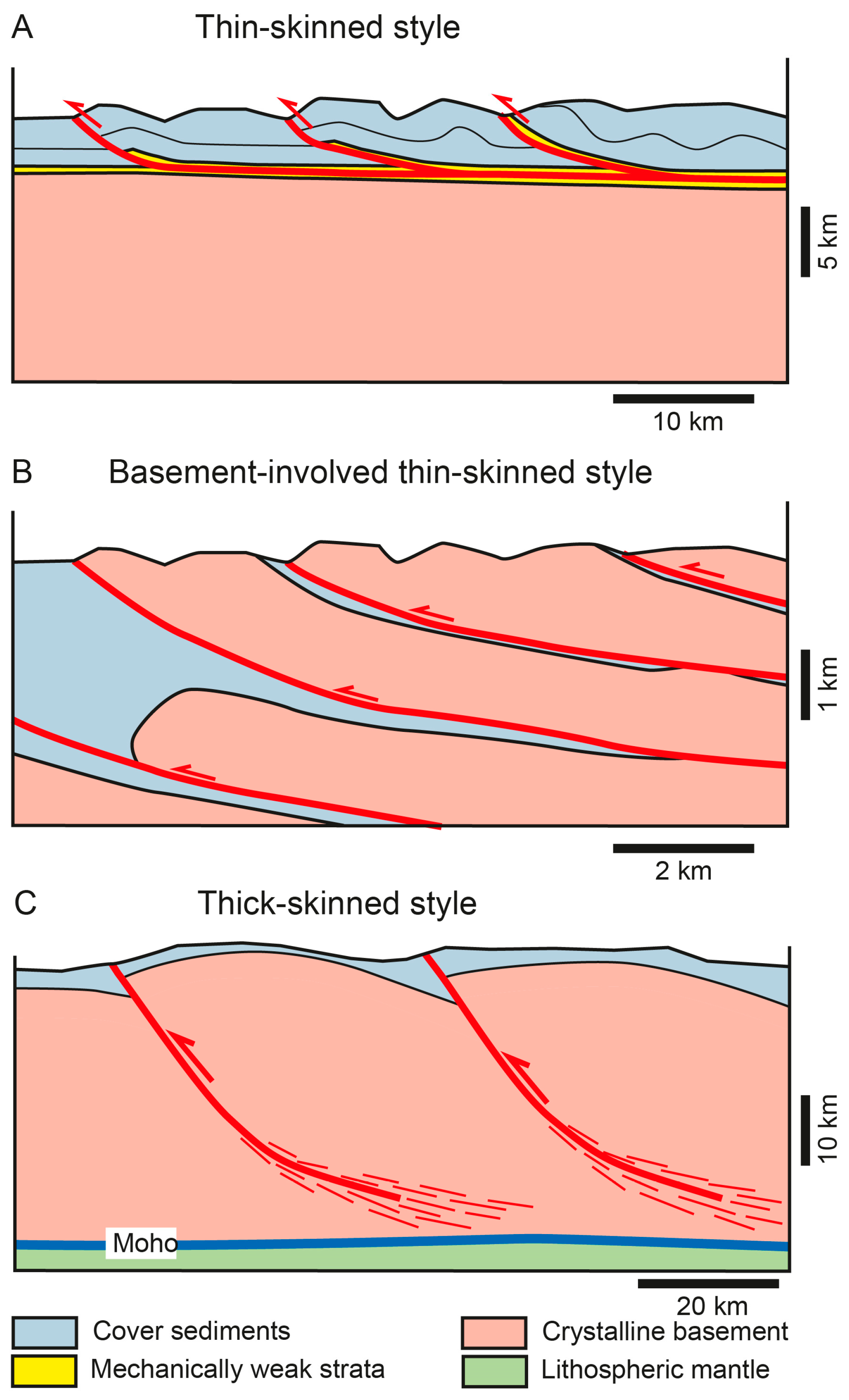
Figure 2.
Cross-sections showing the evolution of thought on thick- and thin-skinned tectonic styles. The cross-sections were redrawn from original published versions. (A) Appalachian structure from the Valley and Ridge to the Blue Ridge province (modified from [5]); (B) Western Central Alps as interpreted by [6]; (C) Scottish Caledonides (redrawn and simplified from [8]; (D) Bhutan Himalaya (redrawn and adapted from [9]); (E) Marañon fold-and-thrust belt of the Central Andes in Peru (adapted from [10]); (F) Sevier fold-and-thrust belt of Wyoming (redrawn from [15]); (G) Arltunga nappe complex of the Ellis Springs orogen in Australia (redrawn from [16]).
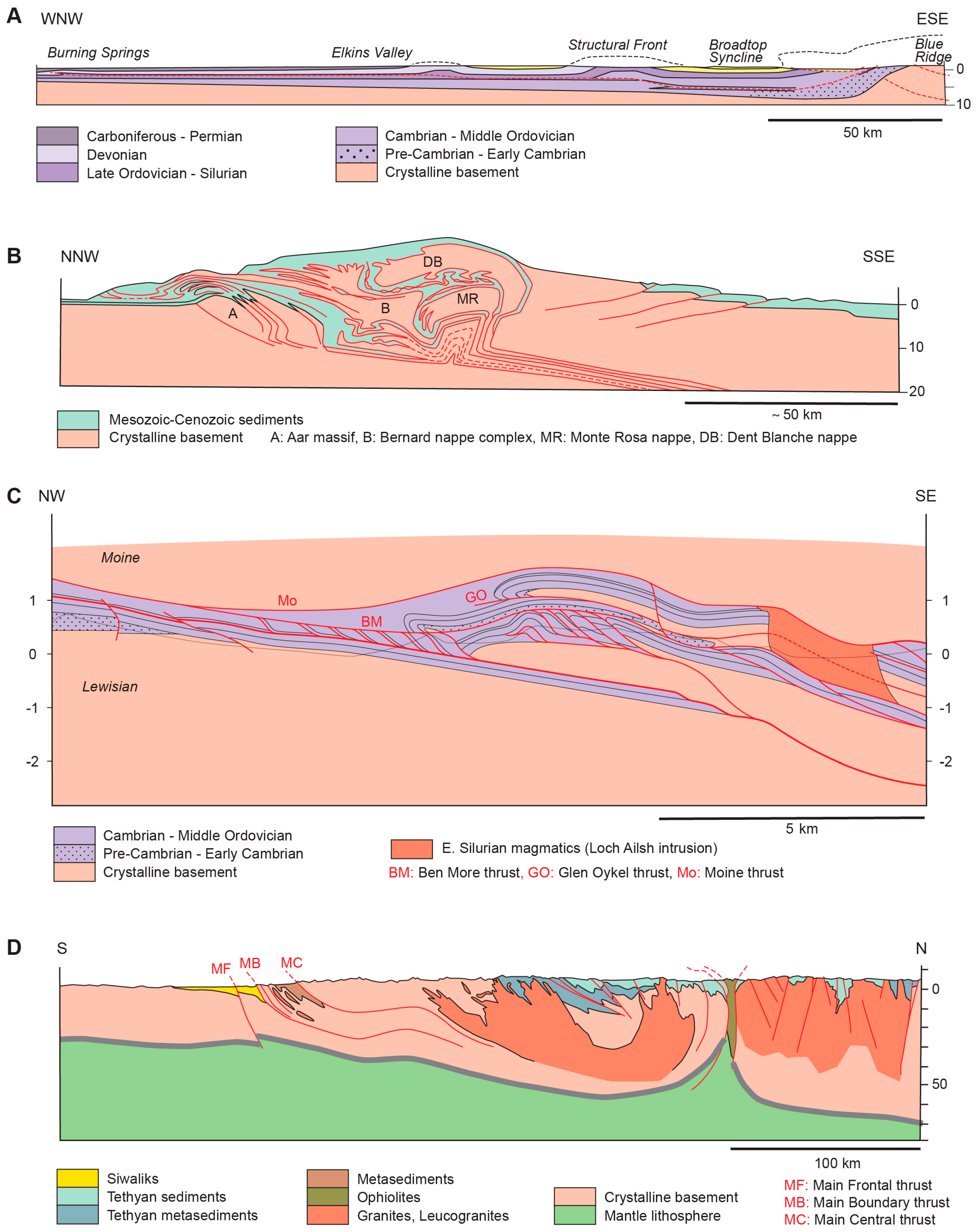
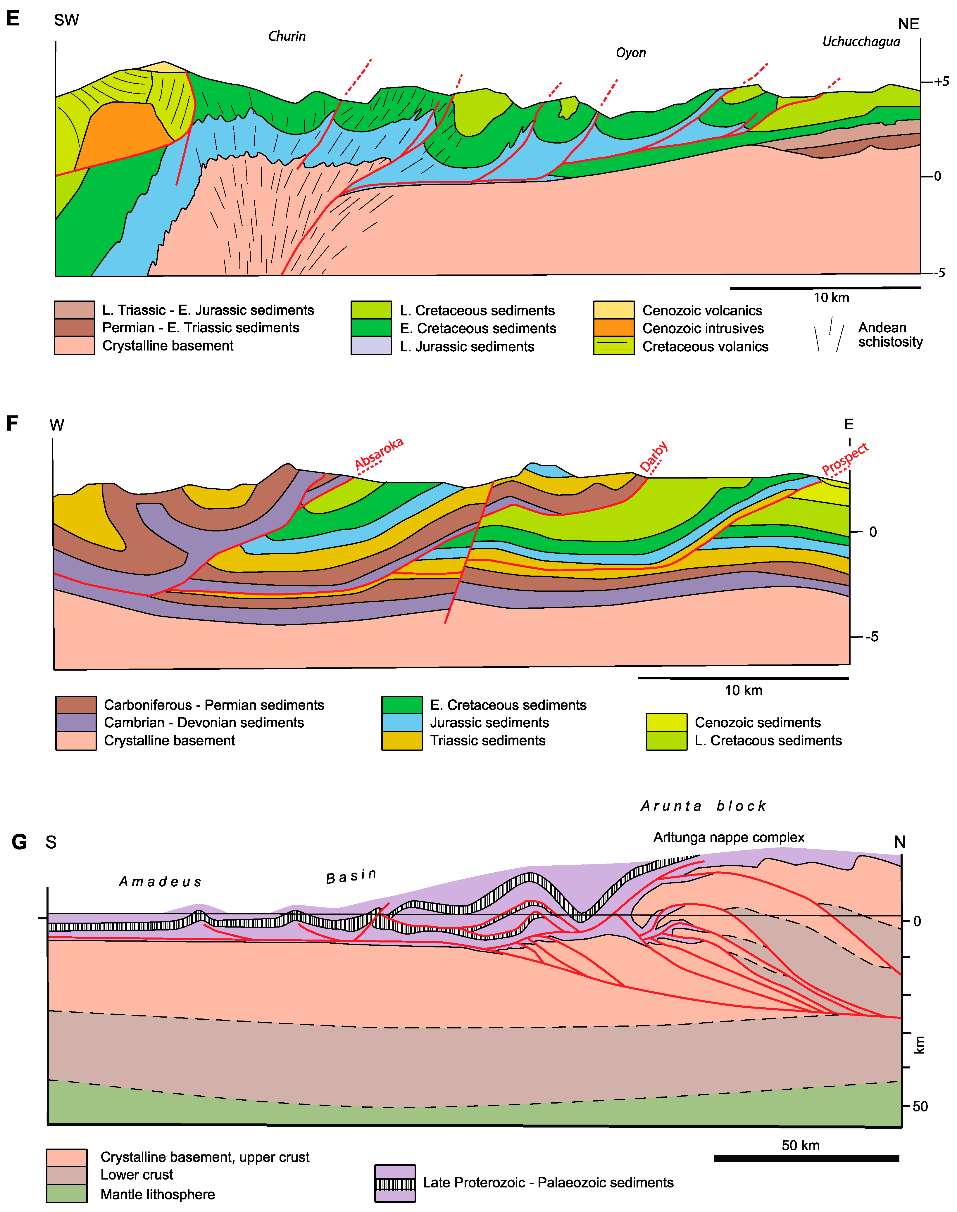
Figure 3.
(A) Diagram showing the trace of future décollements in the Appalachian-Ouachita orogen, valid for areas with thick clastic wedges (based on [26,28]); (B) Cross-section trough the Helvetic nappe system of eastern Switzerland obtained from down-plunge projection. The transition from imbricate thrusting to detachment folding highlighted by the Late Jurassic Quinten Limestone is caused by thickness changes of the mechanically weak layer, a Middle Jurassic sandstone-shale sequence.

Figure 4.
Displacement transfer along thrust faults. See text for discussion.
Figure 5.
Nappe stacks formed by frontal and basal accretion. Simplified drawing of numerical experiment SL2E by [44]. Numbers show sequence of formation of thrust sheets within each of the two sets.
Figure 5.
Nappe stacks formed by frontal and basal accretion. Simplified drawing of numerical experiment SL2E by [44]. Numbers show sequence of formation of thrust sheets within each of the two sets.
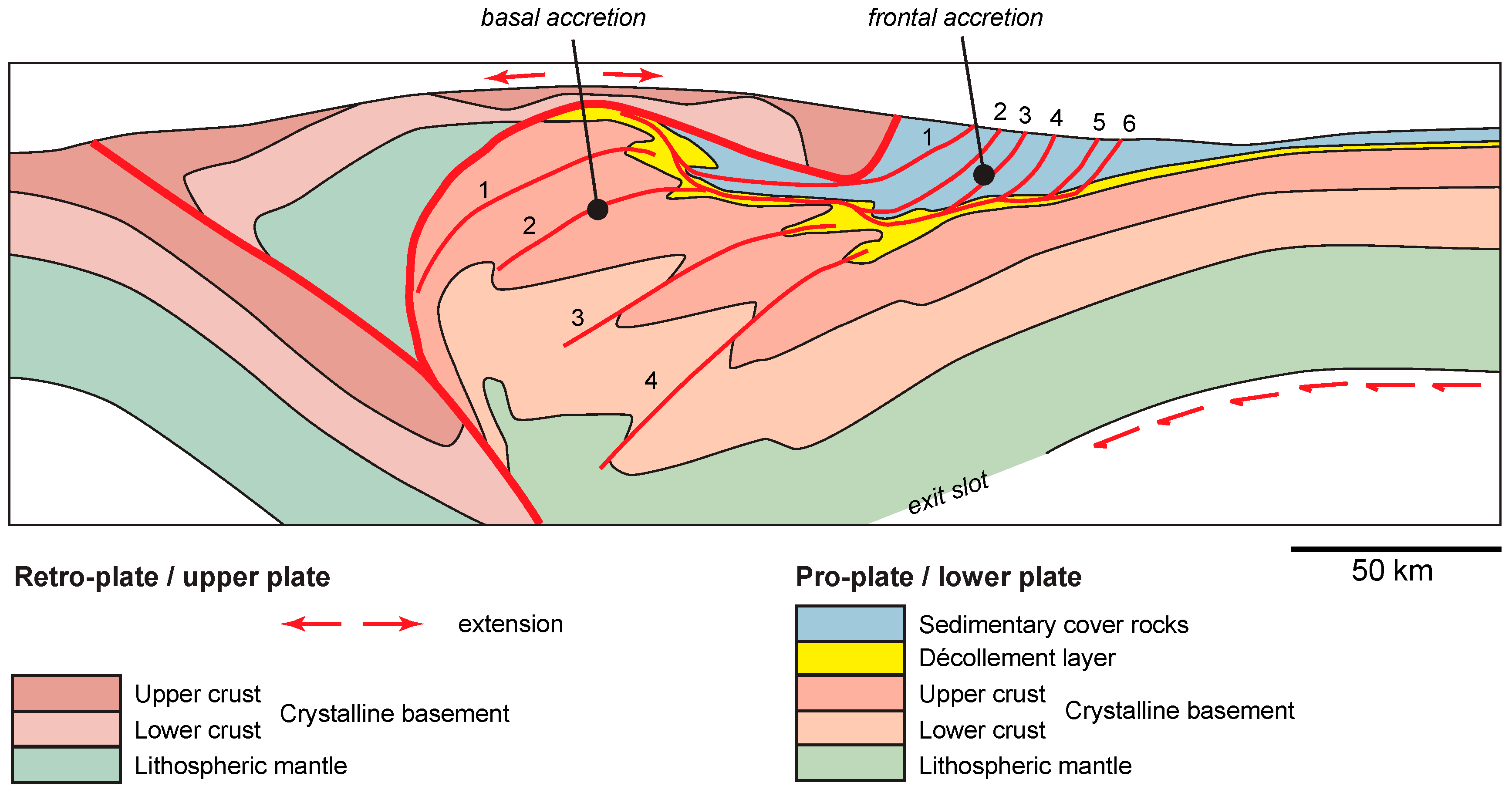
Figure 6.
Inversion of a symmetric rift. Lower diagram shows final rift stage, upper diagram geometry after inversion. Redrawn from [49], their experiment 1 [M17].
Figure 6.
Inversion of a symmetric rift. Lower diagram shows final rift stage, upper diagram geometry after inversion. Redrawn from [49], their experiment 1 [M17].

Figure 7.
Motors of thrust sheet motion—A very simple scheme.
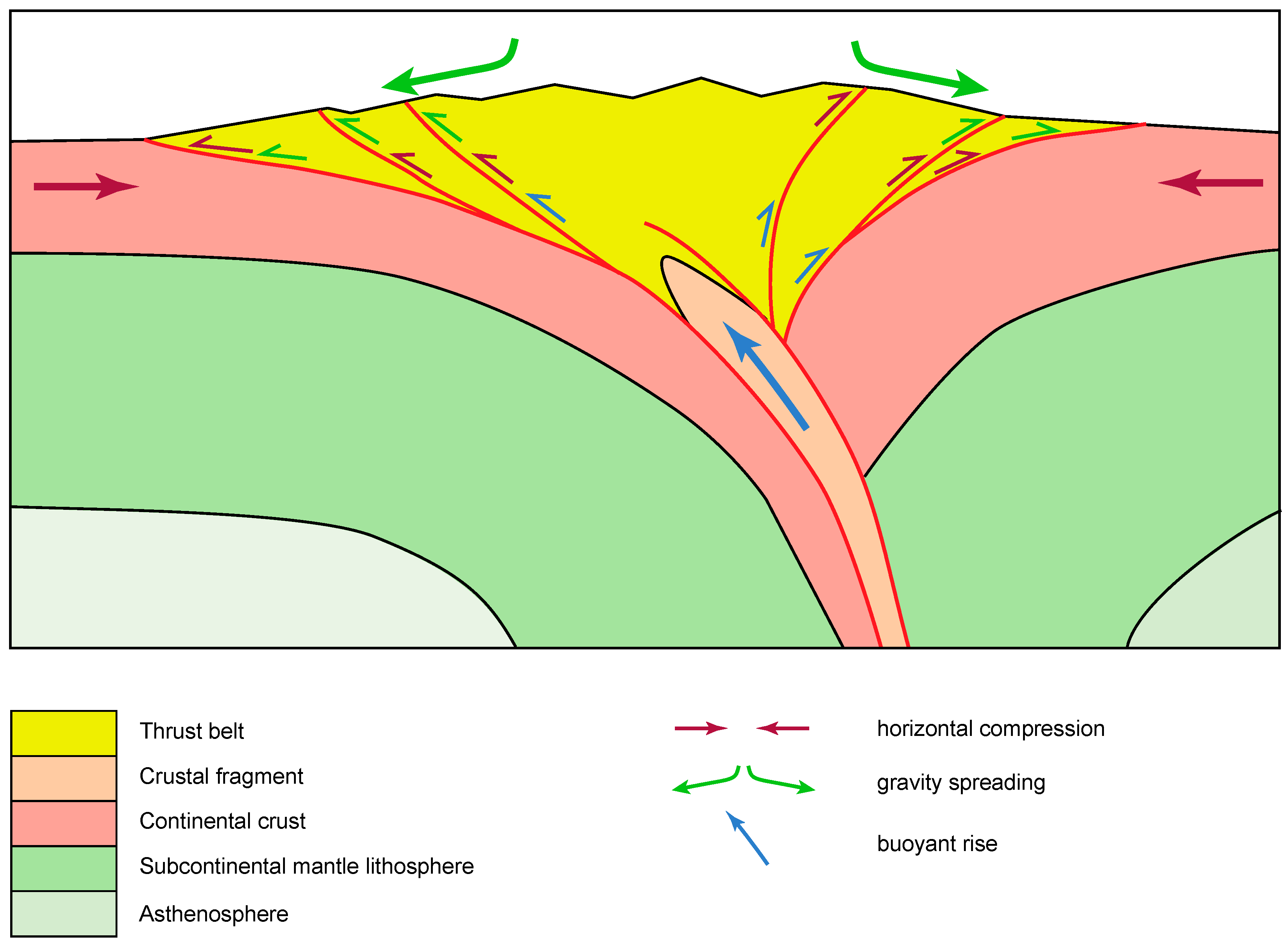
Figure 8.
(A) Schematic tectonic map of North America, with insets of North American Cordillera and Appalachians; (B) Schematic tectonic map of South America, with insets of detailed maps within the Andes; (C1) Schematic tectonic map of Europe—North Africa. (C2) Detailed maps of Caledonian and Variscan orogens within Europe. (C3) Detailed maps of Alpine orogens within Europe and North Africa. (D1) Schematic tectonic map of Eurasia. (D2) Detailed maps of the Zagros Range, the Makran accretionary complex, the Salt Range Potwar Plateau area and the Himalaya; (E1) Schematic tectonic map of Australia. (E2) Detailed maps of the New England orogen and the Alice Springs orogen in Central Australia; (F) Schematic tectonic map of Taiwan.
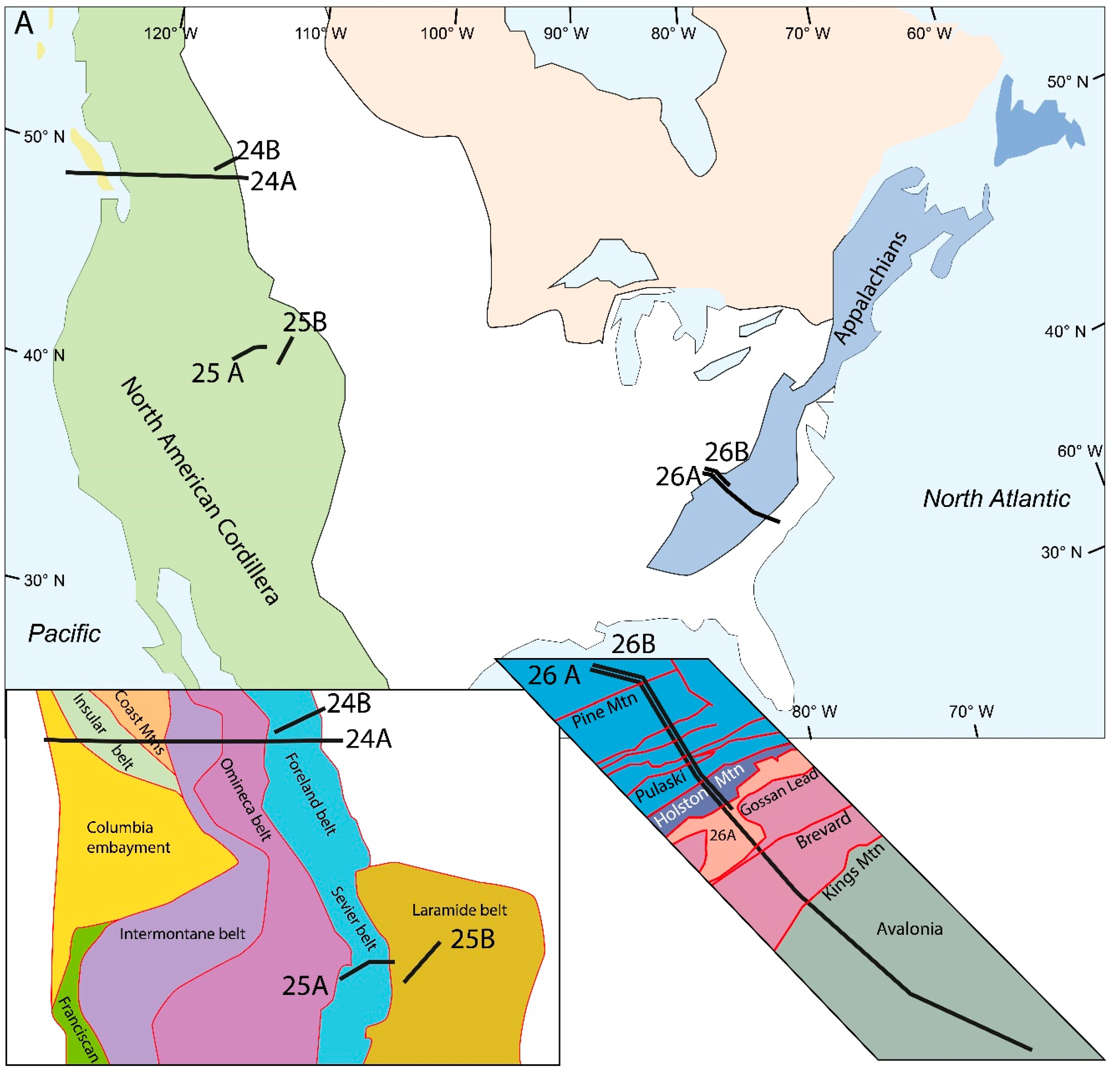

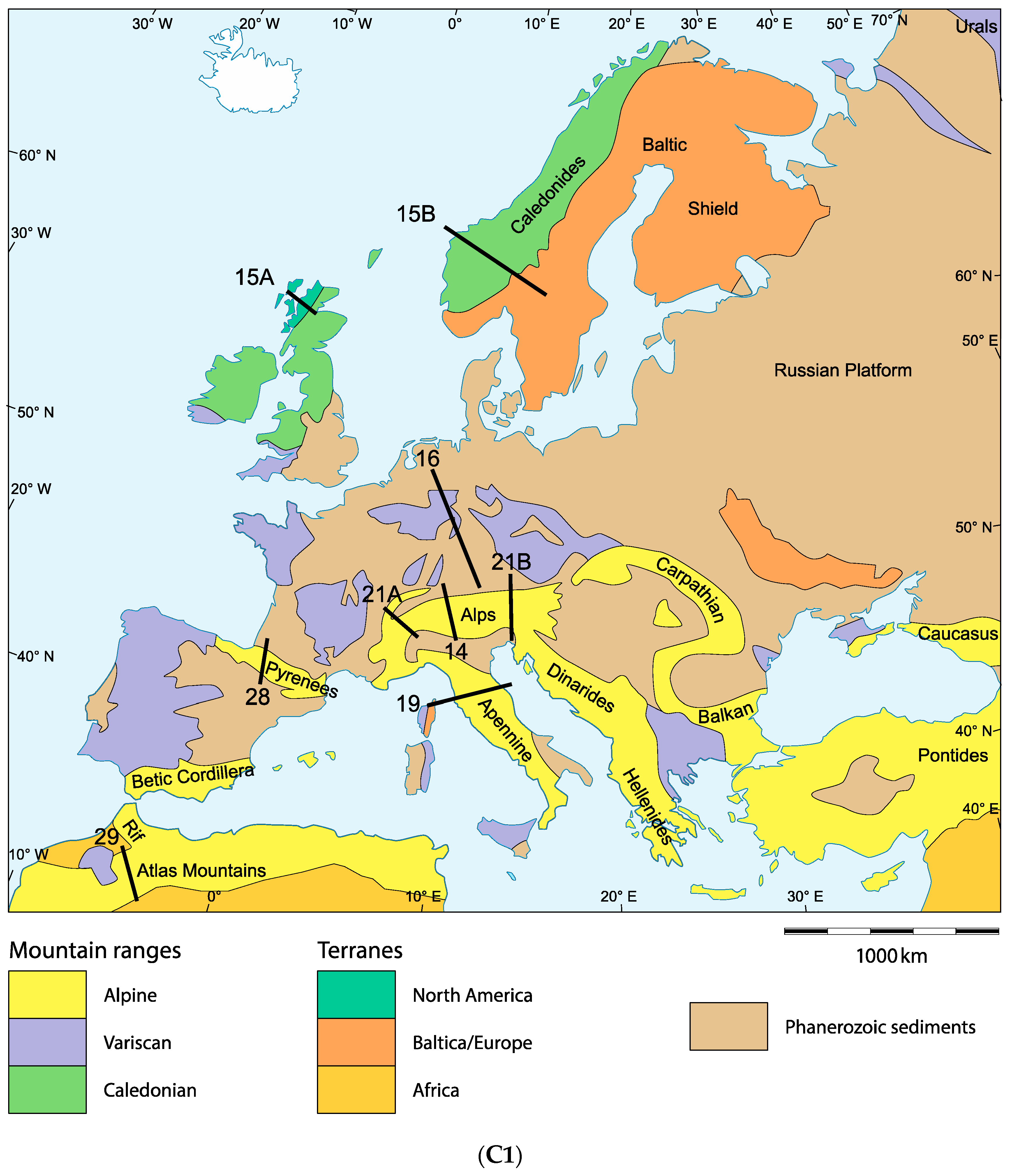
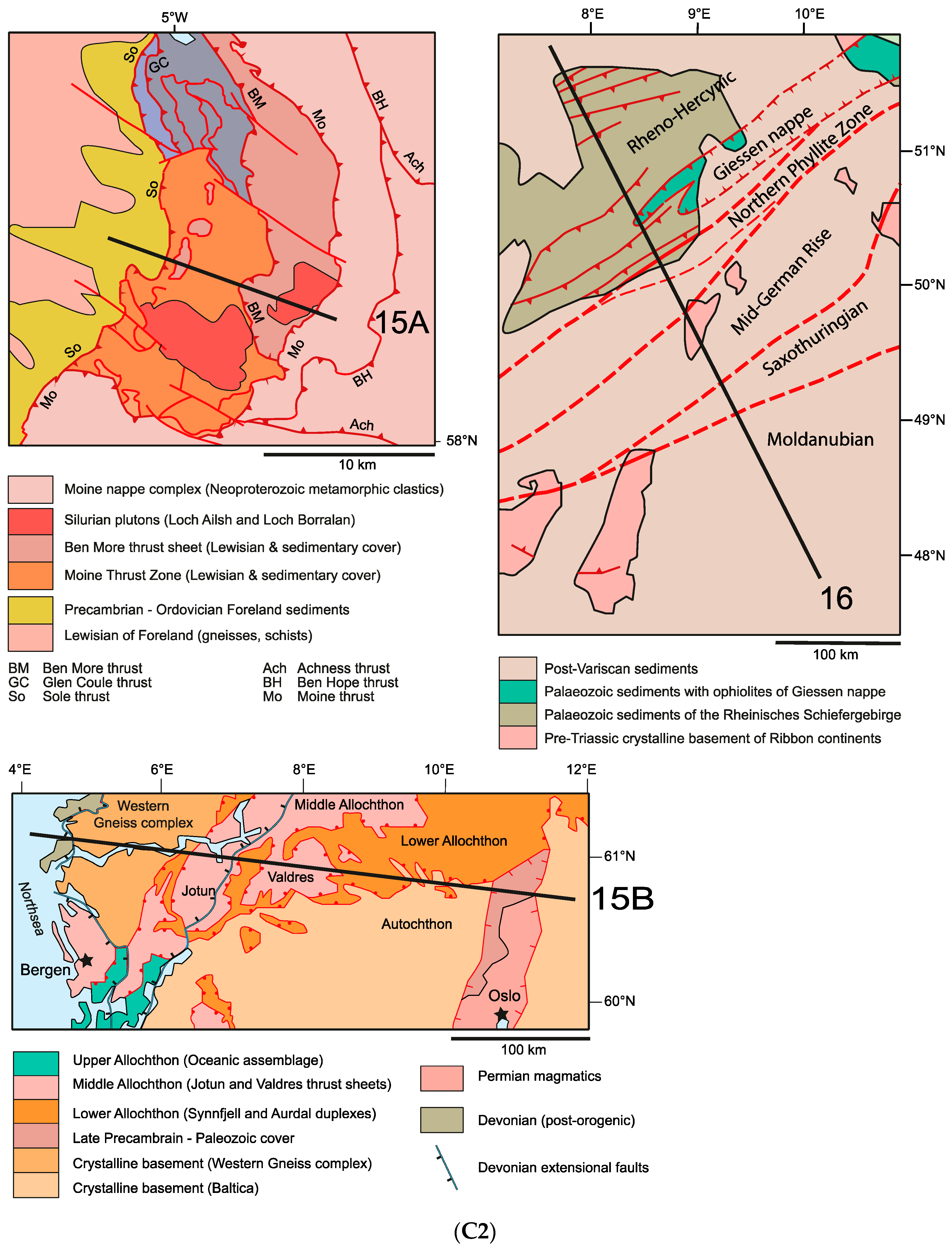


Figure 9.
Cross-section of the Himalaya orogen at ~85° E based on [65,66,67,68,71]. Interseismic velocities from [66]. Trace of cross-section is shown in Figure 8(D1,D2).

Figure 10.
(A) Cross-section of the Central Zagros chain, based on [88,96,97]. Crustal root is cored by thrust faults of the Zagros Imbricate belt. HP/LT belt: high-pressure/low-temperature metamorphic belt. Seismogenic zone after [102]. Trace of cross-section is shown in Figure 8(D1,D2); (B) Cross-section of the Anaran anticline in the northwestern Zagros chain redrawn from [86]. The Anaran anticline is cored by the Main Frontal thrust which offsets the décollement in the Hormuz Formation.
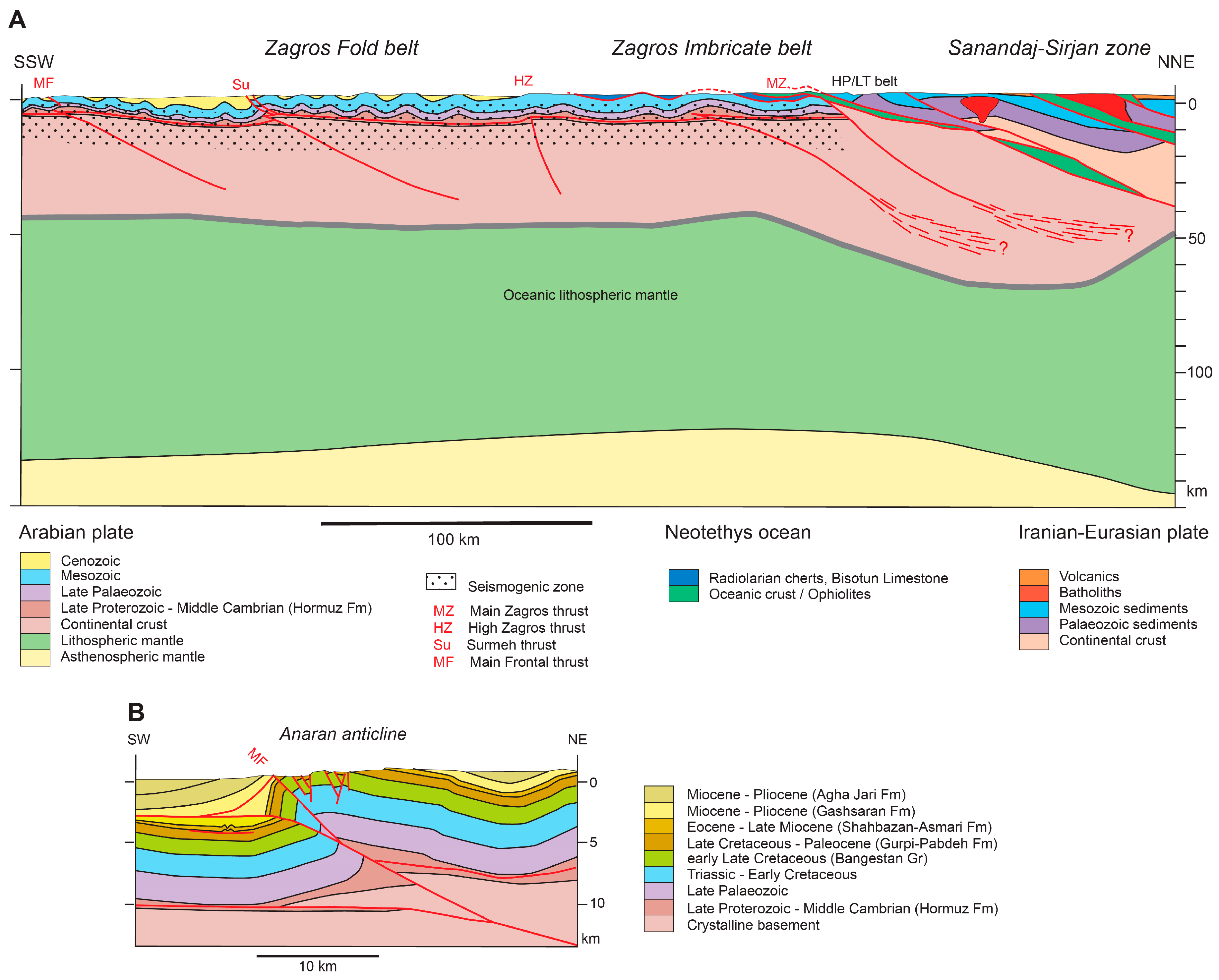
Figure 11.
(A) Cross-section of central Taiwan and adjacent Philippine Sea plate based on [106,112,114]. Earthquake cluster after [117], seismic energy release data after [112], earthquake foci 2016 retrieved from Central Weather Bureau Seismic Network of Taiwan (CWBSN). Uplift rates constructed from [121]. Trace of cross-section is shown in Figure 8F. (B) Cross-section of the Western Foothills and Hsuehshan Range of central Taiwan redrawn from [112]. Cross-section covers western part of Figure 11A.

Figure 12.
(A) Lithosphere-scale cross-section of the Central Andes at 31° S, based on [50,123,126]. Rectangle shows location of Figure 12B. West-directed thrusting in the Sierras Pampeanas opposes east-directed thrusting in the Andes. Trace of cross-section is shown in Figure 8B. (B) Detail of cross-section of the contact zone between the Precordillera and the Sierras Pampeanas, adapted from [126]. Microseismic foci outline a seismogenic upper crust to a depth of around 30 km. A broad band of foci straddle the trace of the Eastern Precordillera thrust and the Pie de Palo thrust, while the foci of major historic earthquakes are thought to be directly linked to these faults.

Figure 13.
(A) Cross-section across the Andes of Colombia, based on [131]. RFS: Romeral fault system. Trace of cross-section is shown in Figure 8B. (B) Cross-section of the Eastern Cordillera of Colombia, redrawn after [129]; earthquake hypocenters from [131,140]. The trace of the cross-section is oblique to the one in Figure 13A and shown in Figure 8B.

Figure 14.
Cross-section of the Central Alps of Switzerland adapted from [148]. Trace of cross-section is shown in Figure 8(C1,C3).
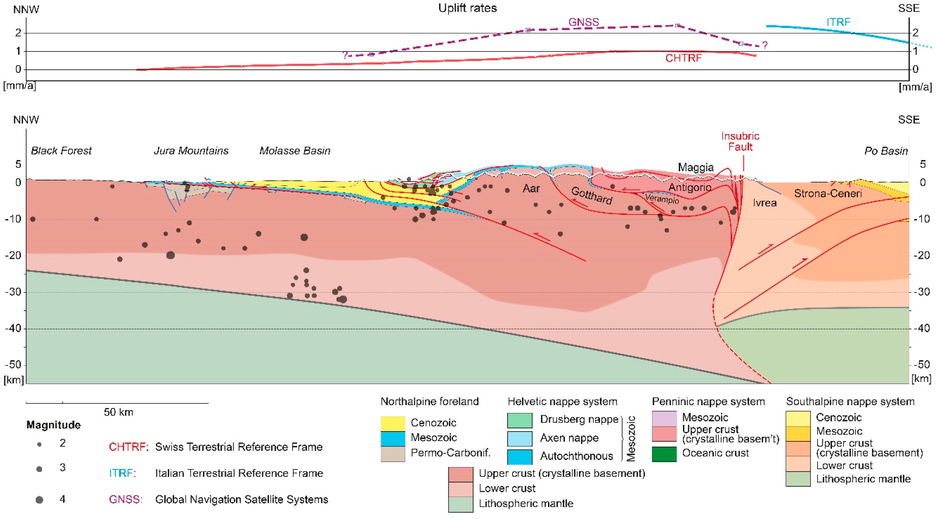
Figure 15.
(A) Cross-section through the Assynt culmination of the Scottish Caledonides. Redrawn from [8] and amended from data by [158]. Trace of cross-section is shown in Figure 8(C1,C2). (B) Cross-section through the Norwegian Caledonides redrawn from [161] and amended with data by [162,163]. Trace of cross-section is shown in Figure 8(C1,C2).
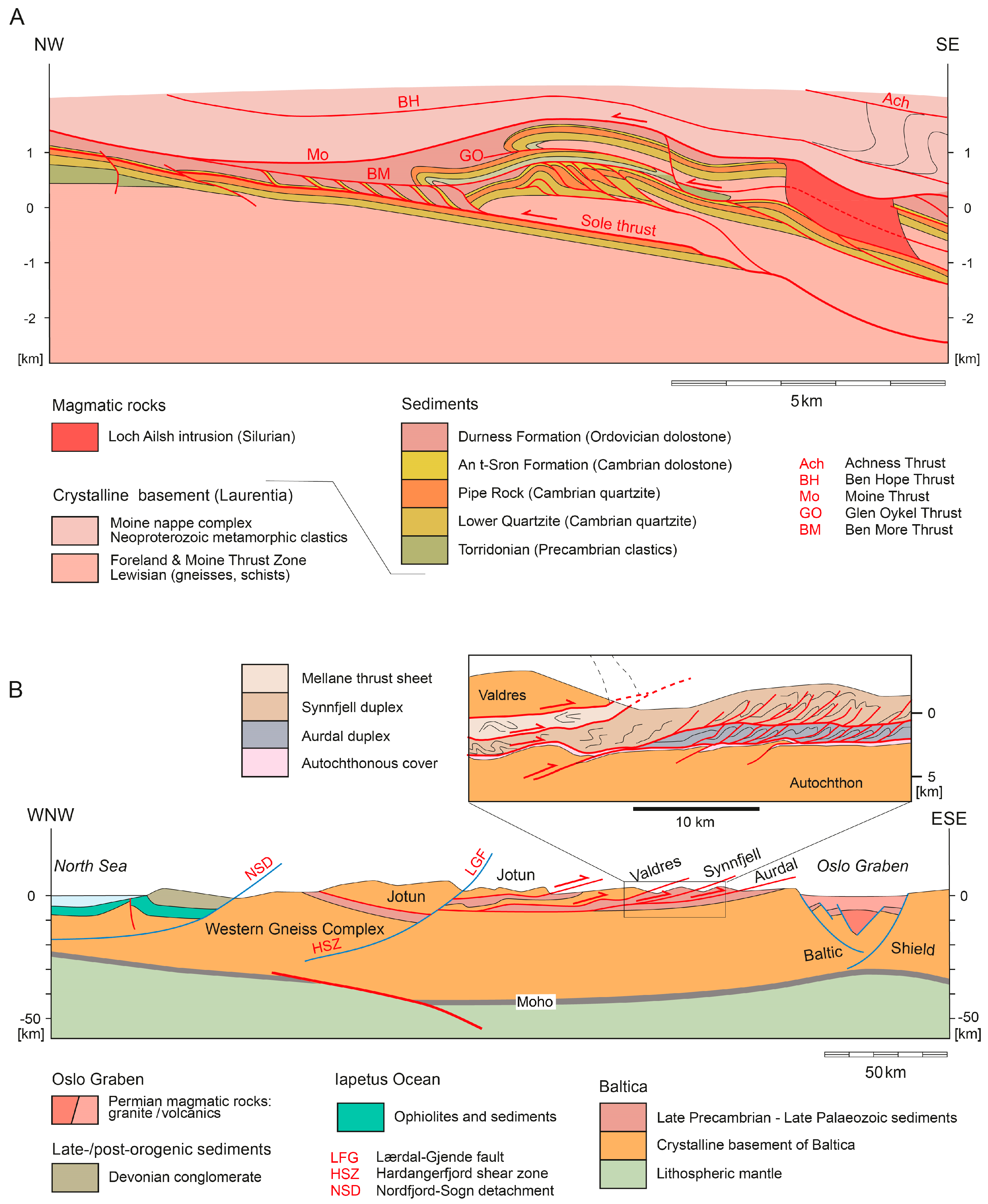
Figure 16.
Cross-section of the German Variscides along the European Geotraverse. Based on [171] and amended by [172,173] and own work. Trace of cross-section is shown in Figure 8(C1,C2).

Figure 17.
Cross-section through the Alice Springs Orogen in central Australia. Redrawn from [16] and amended by seismic data of [176]. Trace of cross-section is shown in Figure 8(E1,E2).

Figure 18.
Cross-section through the Gunnedah Basin, Tamworth belt and New England thrust belt in eastern Australia. Compiled from [178,179,180,181]. Trace of cross-section is shown in Figure 8(E1,E2).

Figure 19.
(A) Cross-section of the Apennine fold-and-thrust belt from Corsica to the Adriatic Sea showing the plate tectonic setting. Based on [184,186]. Trace of cross-section is shown in Figure 8(C1,C3). (B) Detailed cross-section of the Apennine chain and the Adriatic foreland adapted from [185,189] involving a thick-skinned tectonic style and basin inversion tectonics.

Figure 20.
Cross-section of the Himalaya-Tibetan orogen along the INDEPTH traverse based on [72,83,191]. Trace of cross-section is shown in Figure 8(D1,D2).
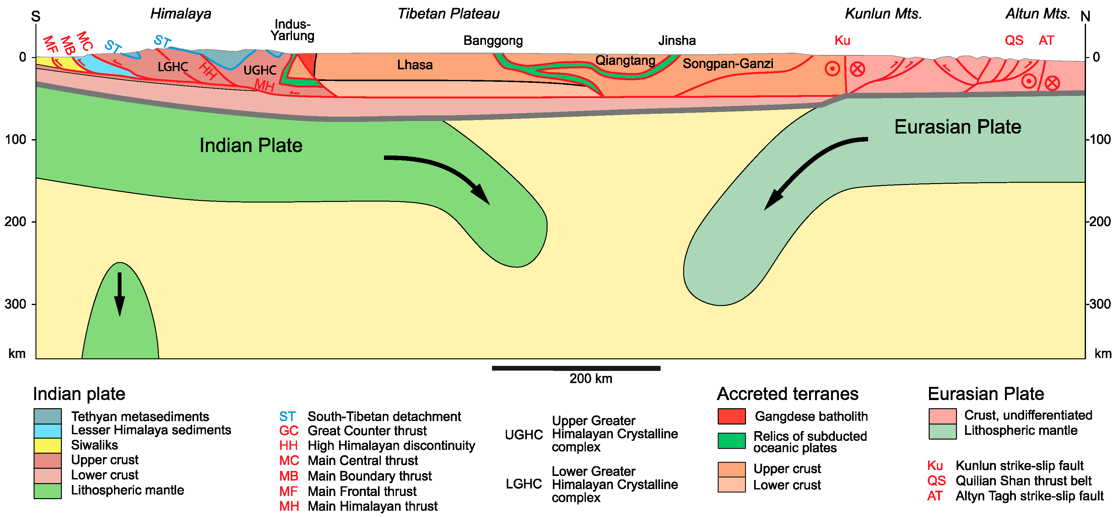
Figure 21.
(A) Cross-section of the Western Alps along the trace of ECORS-CROP. Modified from [142] and references therein. Trace of cross-section is shown in Figure 8(C1,C3). (B) Cross-section of the Eastern Alps parallel to the trace of the German-Austrian and Italian seismic surveys TRANSALP-CROP. Modified from [142] and references therein. Trace of cross-section is shown in Figure 8(C1,C3).


Figure 22.
Central Andes of Peru. (A) Cross-section of the entire range based on [211], showing thick-skinned tectonics at crustal scale. Trace of cross-section is shown in Figure 8B. (B) Cross-section of the Marañon fold-and-thrust belt extending from the Western Cordillera to the Central Highlands based on [211]. The cover displays thin-skinned tectonics. RVQ: Raura–La Viuda–San Jose de Quero fault. (C) Cross-section of the Subandean Zone based on [211] showing thin-skinned tectonics with SW and NE verging thrust faults.

Figure 23.
Cross-section of the Central Andes of Chile-Bolivia at latitude 21° S, based on [221,226,227,228,231,232] showing thick-skinned and thin-skinned tectonics at lithosphere scale. Trace of cross-section is shown in Figure 8B.
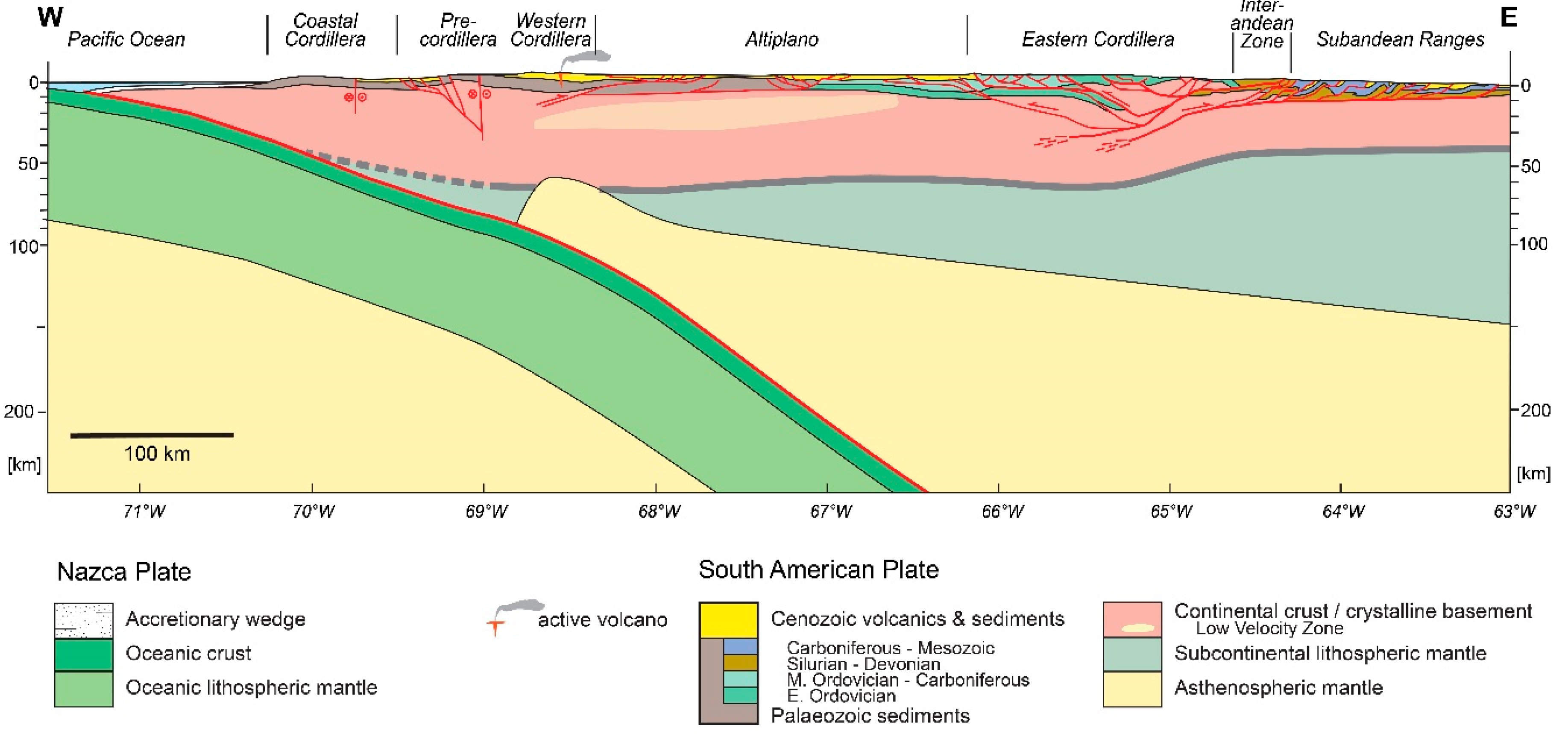
Figure 24.
(A) Cross-section of the North American Cordillera in southern Canada based on [223], LITHOPROBE [238,239,240,241]. Inset: Thick-skinned and thin-skinned tectonics in the Omineca Belt. Trace of cross-section is shown in Figure 8A. (B) Cross-section of the external Foreland belt in Alberta (Canada) redrawn from [236]. Trace of cross-section is shown in Figure 8A.

Figure 25.
Structure of the Sevier and Laramide belt in the western U.S.A. (Idaho-Wyoming). Traces of cross-sections are shown in Figure 8A. (A) Cross-section of the Sevier thrust belt, based on [15,23,235,244]; (B) Cross-section of the Laramide belt based [235,245].
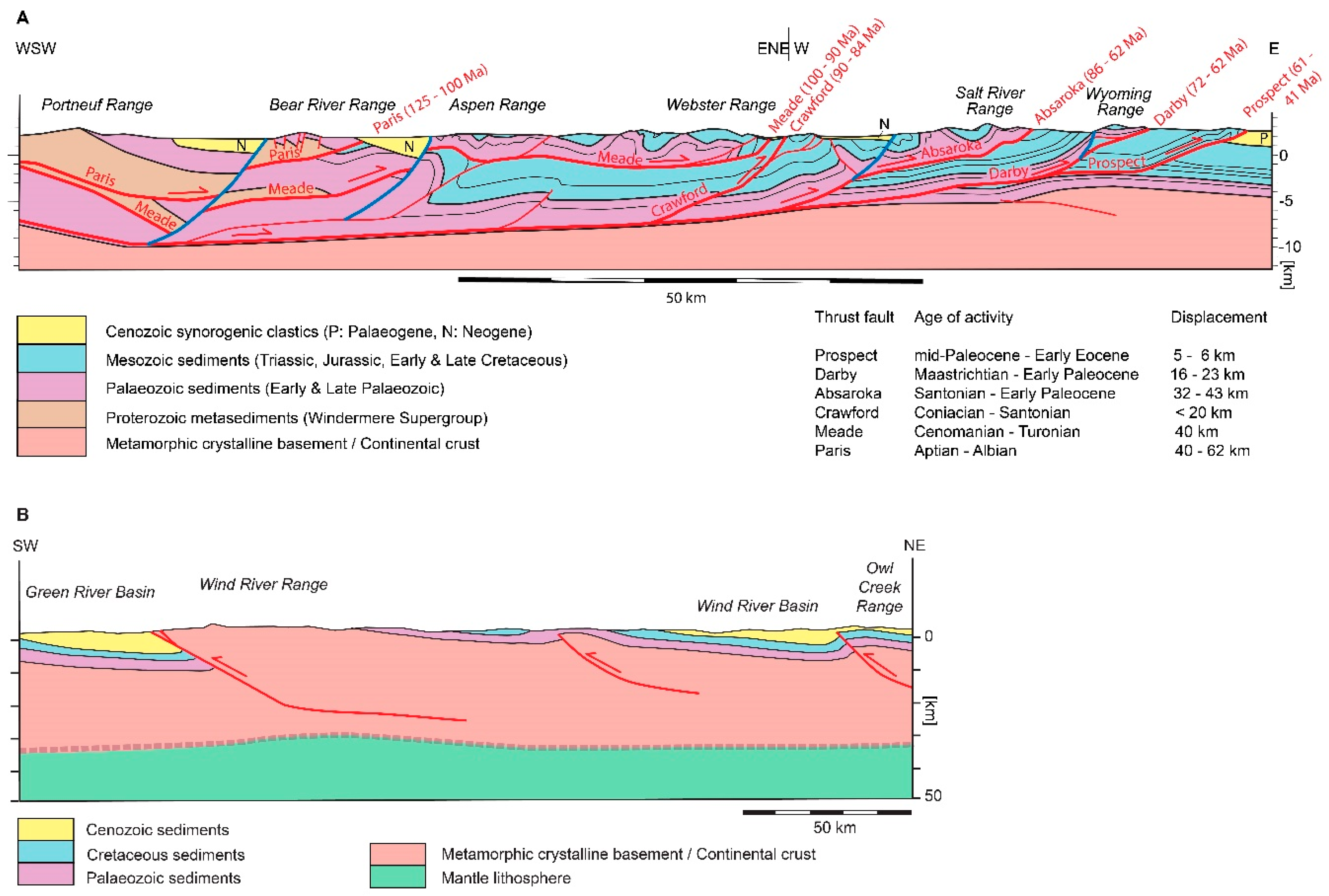
Figure 26.
(A) Cross-section of the Southern Appalachians after D.W. Rankin and S.E. Boyer (slightly modified) in [248]. Moho from geophysical data by [250]. Trace of cross-section is shown in Figure 8A. (B) Detailed cross-section showing the structure of the Cumberland Plateau, the Valley and Ridge Province and the NW part of the Blue Ridge Province after D.W. Rankin and S.E. Boyer (slightly modified) in [248]. Trace of cross-section is shown in Figure 8A.

Figure 27.
Cross-section of the Malargüe fold-and-thrust belt in the Principal Cordillera of Argentina at ~34°55′ S, redrawn from [253] showing the effect of basin inversion on basement involvement. Trace of cross-section is shown in Figure 8B.

Figure 28.
Cross-section of the west Central Pyrenees along the ECORS-Alzacq traverse based on [265,269]. Trace of cross-section is shown in Figure 8(C1,C3).
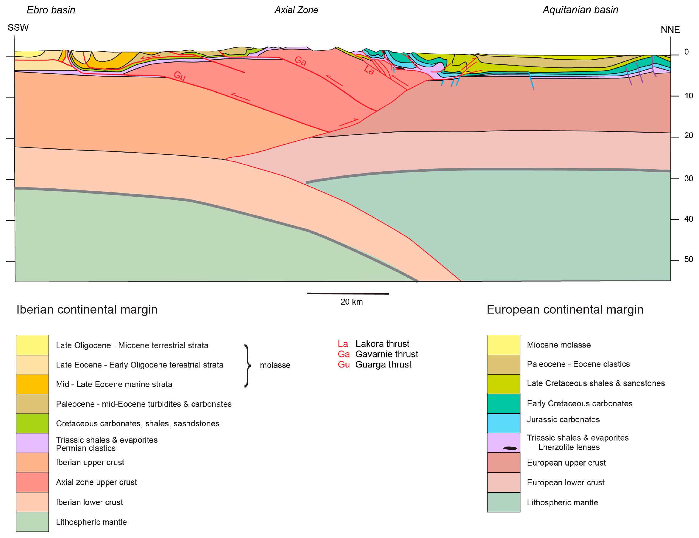
Figure 29.
Cross-section of the Atlas Mountains, redrawn and expanded from [276]. Crustal geometry after [280]. Trace of cross-section is shown in Figure 8(C1,C3).
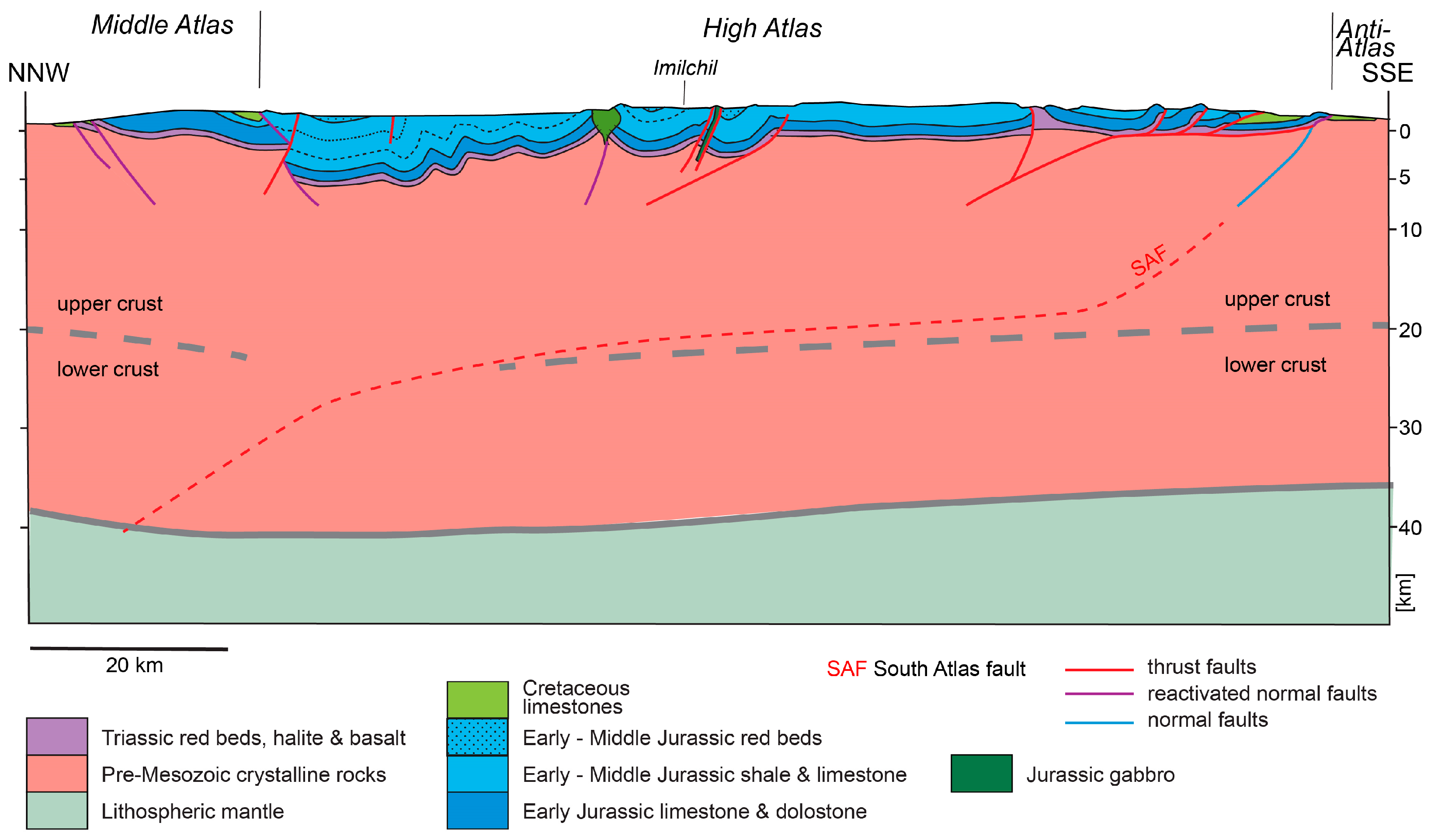
Figure 30.
Structure of the Klippen nappe in western Switzerland (redrawn from [285]) showing the role of syn-sedimentary faults on thrust tectonics. (A) Retrodeformed cross-section showing the basin geometry prior to Alpine contraction. (B) Cross-section showing recent state after Alpine contraction. Trace of cross-section is shown in Figure 8.

Figure 31.
Cross-sections highlighting the structure of the Potwar Plateau—Salt Range of Pakistan. Traces of cross-sections are shown in Figure 8(D1,D2). (A) Schematic cross-section within the Northwest Himalaya Syntax. Recent seismicity is based on [287,292]. (B) Cross-section of central Potwar Plateau–Salt Range, redrawn after [288]. (C) Cross-section of eastern Potwar Plateau–Salt Range, redrawn after [289].
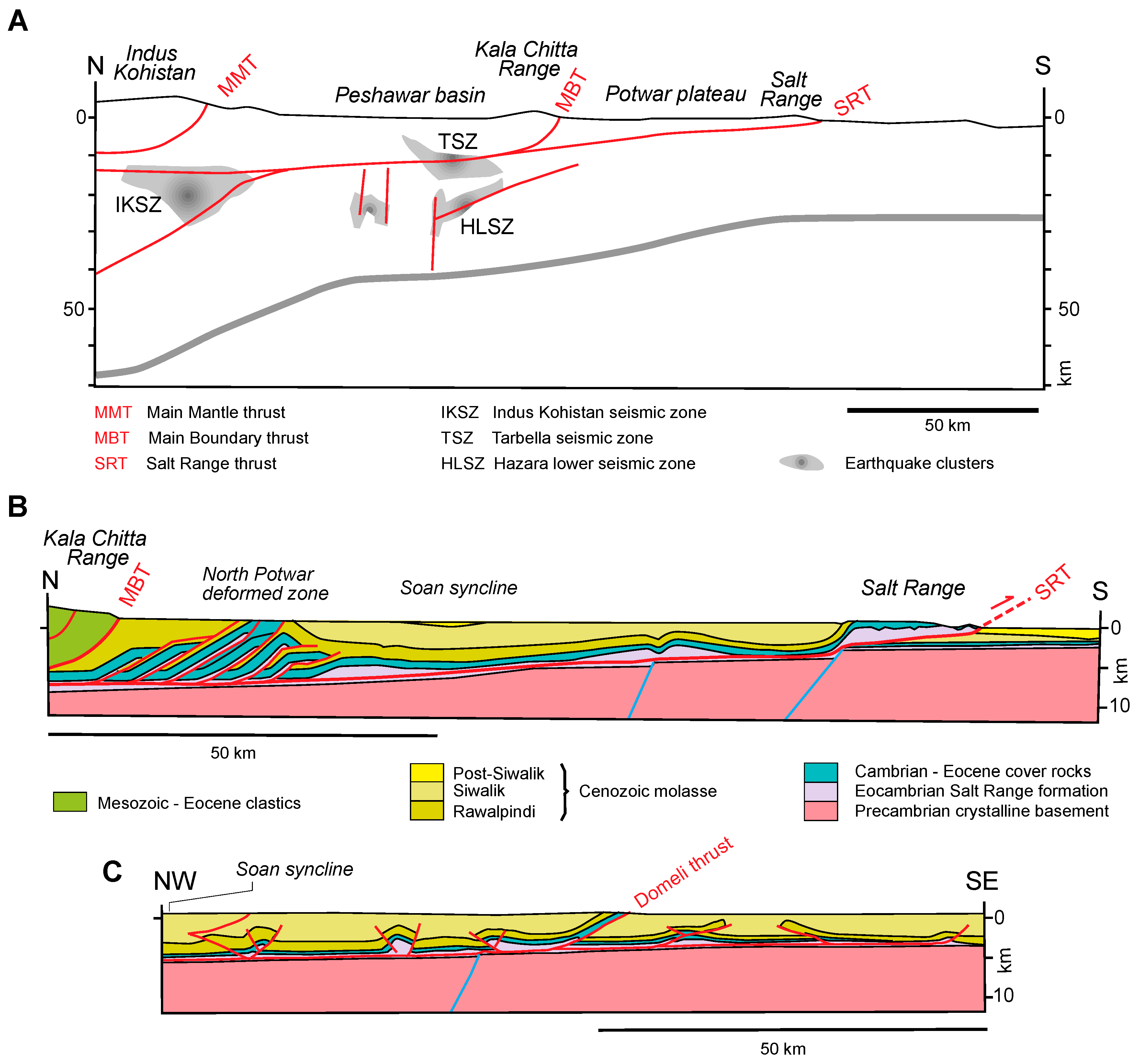
Figure 32.
Synoptic cross-section of the Makran accretionary wedge at 60–63° E, based on [300,301,302]. Trace of cross-section is shown in Figure 8(D1,D2).

Figure 33.
Cartoons showing principal features of the various types of orogens. (A) Collision related; (B) subduction related; (C) Rigid slab of continental crust; (D) Deformed continental crust; (E) Basin inversion; (F) Detached allochthonous cover.
Figure 33.
Cartoons showing principal features of the various types of orogens. (A) Collision related; (B) subduction related; (C) Rigid slab of continental crust; (D) Deformed continental crust; (E) Basin inversion; (F) Detached allochthonous cover.
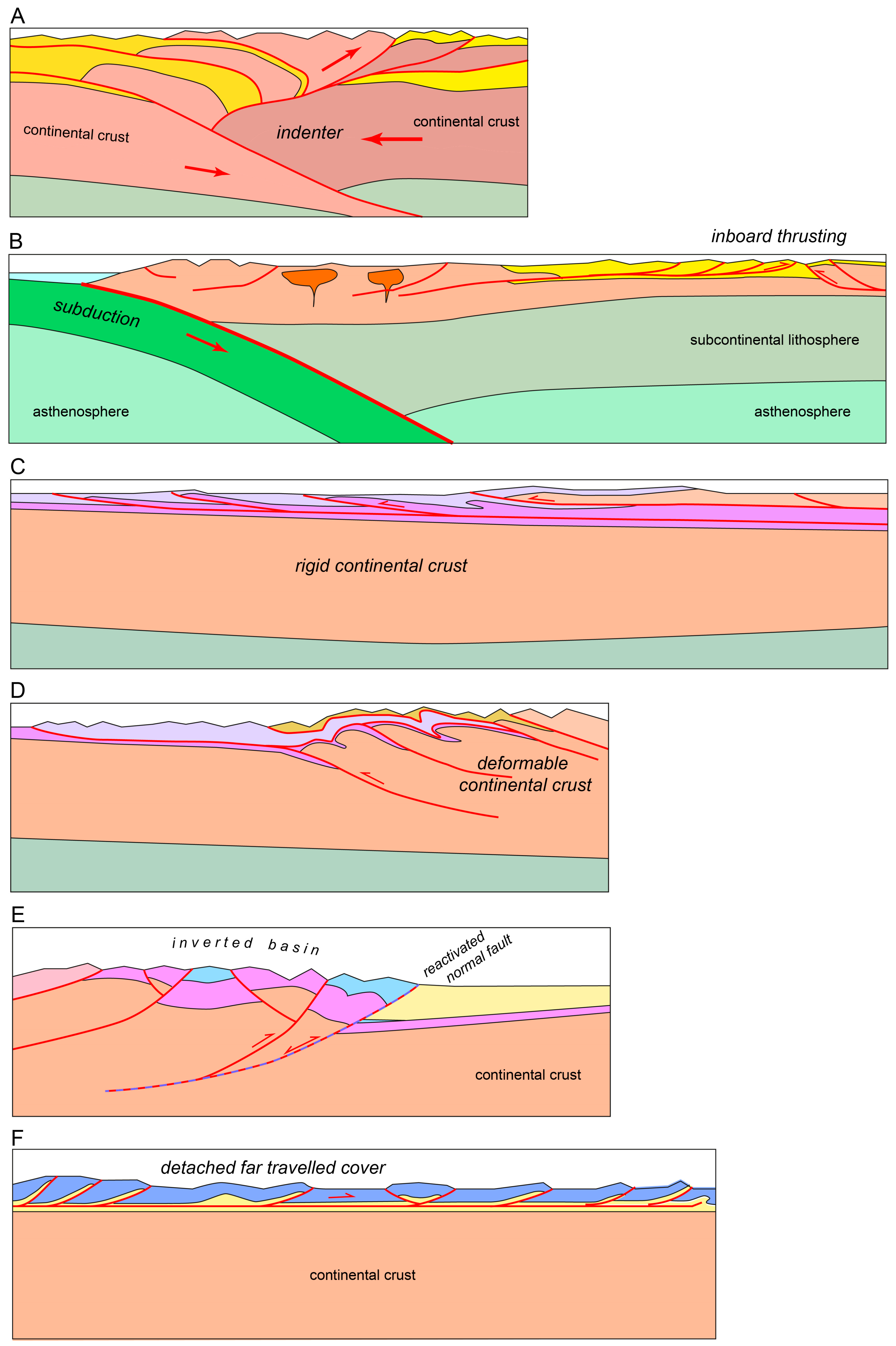
© 2017 by the author. Licensee MDPI, Basel, Switzerland. This article is an open access article distributed under the terms and conditions of the Creative Commons Attribution (CC BY) license (http://creativecommons.org/licenses/by/4.0/).
Share and Cite
MDPI and ACS Style
Pfiffner, O.A. Thick-Skinned and Thin-Skinned Tectonics: A Global Perspective. Geosciences 2017, 7, 71. https://doi.org/10.3390/geosciences7030071
AMA Style
Pfiffner OA. Thick-Skinned and Thin-Skinned Tectonics: A Global Perspective. Geosciences. 2017; 7(3):71. https://doi.org/10.3390/geosciences7030071
Chicago/Turabian StylePfiffner, O. Adrian. 2017. "Thick-Skinned and Thin-Skinned Tectonics: A Global Perspective" Geosciences 7, no. 3: 71. https://doi.org/10.3390/geosciences7030071
Note that from the first issue of 2016, this journal uses article numbers instead of page numbers. See further details here.