Single-Grating Monochromators for Extreme-Ultraviolet Ultrashort Pulses

National Council for Research of Italy, Institute of Photonics and Nanotechnologies, via Trasea 7, 35131-Padova, Italy
*
Author to whom correspondence should be addressed.
Appl. Sci. 2013, 3(1), 1-13; https://doi.org/10.3390/app3010001
Submission received: 26 November 2012
/
Revised: 11 December 2012
/
Accepted: 18 December 2012
/
Published: 27 December 2012
(This article belongs to the Special Issue Ultraintense Ultrashort Pulse Lasers)
Abstract
:A single-grating monochromator can be used for the spectral selection of ultrashort pulses without altering in a significant way the pulse duration, provided that the number of illuminated grooves is equal to the resolution. Two configurations are compared: the classical-diffraction mount (CDM) and the off-plane mount (OPM). The advantages and drawbacks of both configurations are presented. The two geometries can be joined in a new and innovative design of a monochromator with two interchangeable diffracting stages both used at grazing incidence, one with the gratings in the CDM and the other in the OPM. The use of two stages gives great flexibility: the OPM stage is used for sub-50 fs time response and low spectral resolution and the CDM stage for 100-200 fs time response and high spectral resolution. The design overcomes the limits of the two single configurations, giving on the same instrument either ultrafast response with low spectral resolution or slower response with higher resolution.
1. Introduction
Laser pulses as short as a few femtoseconds are nowadays available for high-resolution time-domain spectroscopic applications to many areas of science from solid-state physics to biology [1]. While optical lasers have offered unique insights into ultra-fast femtosecond dynamics, structural arrangement and motion of nuclei are not directly accessible from measured optical properties. This gap has been filled by the availability of coherent ultrashort sources in the extreme-ultraviolet (XUV) and soft X-rays, such as high-order laser harmonics (HHs) and free-electron-lasers (FELs).
HHs, which are generated through nonlinear interaction between atoms and ultrashort laser pulses, are table-top ultrashort sources with high brightness, coherence and peak intensity [2]. The HH spectrum is described as a sequence of peaks corresponding to the odd harmonics of the fundamental laser wavelength with an intensity distribution characterized by a plateau whose extension is related to the pulse intensity. The combination of the use of advanced phase matching mechanisms and interaction geometries, as well as intense ultrafast laser has made it possible to obtain HH radiation up to the water window region (2.3-4.4 nm) [3,4]. Moreover, the radiation generated with the scheme of the HHs using few-optical-cycles laser pulses is nowadays the main tool for the investigation of matter with sub-femtosecond resolution [5,6]. The use of the XUV emission in a narrow band requires the spectral selection of a single harmonic with a suitable monochromator that has to preserve the temporal duration of the XUV pulse as short as the time resolution required for the experiment.
Free-electron-laser (FEL) sources are nowadays available to generate spatially coherent XUV/X-ray radiation with characteristics similar to the light from conventional optical lasers, ultrashort time duration and an increase of 6-8 orders of magnitude on the peak brilliance with respect to third-generation synchrotron sources [7,8,9]. Monochromators may be required in FEL beamlines either to increase the spectral purity of the source or to select the FEL radiation at the high harmonics and to filter out the fundamental [10].
The monochromator demanded for the spectral selection of ultrashort pulses has to preserve the temporal duration as short as in the generation process. A time broadening can be tolerated if the pulse duration at the output is maintained anyway shorter than the temporal resolution required by the experiment. For a Gaussian profile with no phase or frequency modulation, the half-height duration Δτhas a lower limit expressed by:
![Applsci 03 00001 i001]() where λ is the pulse central wavelength, Δλ is the half-height spectral width of the pulse and c is the speed of light in vacuum. In order to preserve the pulse duration at the output, the bandwidth that is selected by the monochromator has to be larger than Δλ and the transfer function has to be almost constant within the bandwidth. The latter condition is always verified if the monochromator is realized by reflecting optics, since the variations of the reflectivity within the bandwidth Δλ are usually negligible.
where λ is the pulse central wavelength, Δλ is the half-height spectral width of the pulse and c is the speed of light in vacuum. In order to preserve the pulse duration at the output, the bandwidth that is selected by the monochromator has to be larger than Δλ and the transfer function has to be almost constant within the bandwidth. The latter condition is always verified if the monochromator is realized by reflecting optics, since the variations of the reflectivity within the bandwidth Δλ are usually negligible.

The use of XUV monochromators realized by gratings at grazing incidence is discussed here. A grating introduces inevitably a stretch of the pulse duration by the pulse-front tilt, giving a distortion of the temporal profile of the pulse. In fact, each ray that is diffracted by two adjacent grooves is delayed by mλ, where m is the diffraction order. The pulse-front tilt is given by the total difference in the optical paths of the diffracted beam, that is mλN, where N is the number of the illuminated grooves. For example, let us consider a 200 gr/mm grating illuminated by radiation at 20 nm over a surface of 10 mm. The number of grooves that is involved in diffraction is 2000, giving a pulse-front tilt of 40 μm, i.e., 130 fs, that cannot be neglected for few-femtosecond pulses. Nevertheless, it is possible to realize grating monochromators that do not alter the temporal duration of ultrashort pulses by using two gratings in a time-delay compensated configuration, where the second grating compensates for the time and spectral spread introduced by the first one [11,12,13,14]. Pulses as short as 8 fs have been measured at the output of a double-grating monochromator at 35 nm (H23 of Ti:Sa laser) [15]. The main drawback of these configurations is the use of two gratings that increase the complexity and reduce the efficiency.
Let us analyze the conditions to have the minimum temporal broadening from a single grating. Once the output bandwidth Δλ has been defined the minimum number of grooves Nmin that have to be illuminated to support such a bandwidth is |m|Nmin = λ/Δλ [16]. The corresponding minimum pulse front-tilt at half-width that can be obtained by a single grating, ΔτG,min, is:
![Applsci 03 00001 i002]() that is close to the Fourier limit given by Equation 1. Therefore, a single grating may be used for the spectral selection of ultrashort pulses without altering in a significant way the pulse duration, provided that the number of illuminated grooves at first diffraction order is equal to the actual resolution.
that is close to the Fourier limit given by Equation 1. Therefore, a single grating may be used for the spectral selection of ultrashort pulses without altering in a significant way the pulse duration, provided that the number of illuminated grooves at first diffraction order is equal to the actual resolution.

In this paper, we analyze two configurations for the spectral selection of ultrashort pulses: the classical-diffraction mount and the off-plane mount. We discuss the advantages and drawback of both mountings and present a configuration, where the two geometries are joined in a new and innovative design, which overcomes the limits of the two single configurations. The design allows us to realize a broad-band grazing-incidence single-grating monochromator with either ultrafast time response with low spectral resolution or a longer time response with higher resolution.
2. Design of Single-Grating Monochromators for Ultrashort Pulses
Grazing-incidence diffraction gratings may be used in two different geometries: the classical-diffraction mount (CDM) and the off-plane mount (OPM).
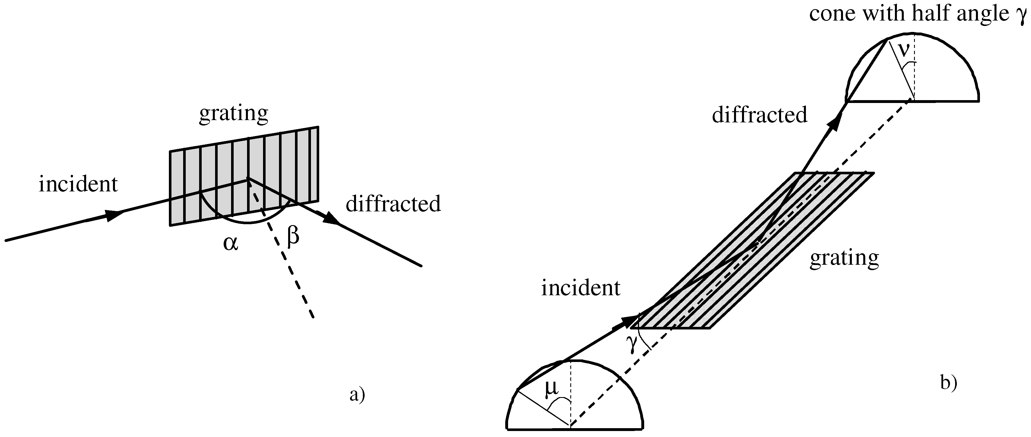
The CDM is shown in Figure 1a. The grating equation is sinα − sinβ = mλσc, where α and β are, respectively, the incidence and diffraction angles (both defined with positive signs), λ is the wavelength, m the diffracted order and σc the groove density. In the case of a monochromator, the grating equation is expressed as:
![Applsci 03 00001 i003]() where K is the subtended angle and β = K − α. The number of illuminated grooves is Nc = S σc/cosα, where S is the beam section on the grating measured in the direction normal to the light propagation. The illuminated grooves are lower in the case m = −1, i.e., the external diffracted order, since α is smaller. In the following, the grating in the CDM will be assumed to be operated in the external diffracted order, to maintain the number of illuminated grooves as small as possible.
where K is the subtended angle and β = K − α. The number of illuminated grooves is Nc = S σc/cosα, where S is the beam section on the grating measured in the direction normal to the light propagation. The illuminated grooves are lower in the case m = −1, i.e., the external diffracted order, since α is smaller. In the following, the grating in the CDM will be assumed to be operated in the external diffracted order, to maintain the number of illuminated grooves as small as possible.

The OPM is shown in Figure 1b. The grating equation is sinγ (sinμ + sinν) = mλσo, where σo is the groove density, γ is the altitude defined as the angle between the direction of the incoming rays and the direction of the grooves and μ and ν are, respectively, the azimuth of the incoming and diffracted rays. The azimuth is defined to be zero if the rays lie in the plane perpendicular to the grating surface and parallel to the rulings. In the case of a monochromator, the grating is operated in the condition μ = ν and the grating equation is:

The number of illuminated grooves is No = S σo/cosμ ≈ S σo. Here, and in the following, it will be assumed μ ≤ 15°, therefore cosμ ≈ 1. This approximation is fully verified for low-resolution configurations, as those that will be presented below. The grating in the OPM can be used indifferently at the orders m = ±1, since this does not affect the illuminated area.
In both configurations, the wavelength selection is performed by rotating the grating around the axis that is tangent to the surface, passes through the grating center and is parallel to the grooves.
Figure 1.
The grating geometry: (a) classical-diffraction mount (CDM); (b) off-plane mount(OPM).
For saw-tooth groove profiles, the blaze condition is the configuration for which the diffraction efficiency is maximized, that is, when the diffracted light leaves the grating in such a way to perform a specular reflection on the groove surface. This is verified for δ = (αβ)/2 = (α − K/2), in the case of the CDM, and for δ = μ, in the case of the OPM, where δ is the grating blaze angle. The main advantage of the OPM when compared to the CDM is the higher efficiency, since it has been theoretically demonstrated and experimentally measured that the peak diffraction efficiency in the OPM is close to the reflectivity of the coating at the altitude angle [17,18]. Therefore, the OPM is a good candidate for the design of XUV monochromators with high efficiency [19]. On the contrary, the OPM has two main drawbacks for the design of XUV monochromators. First of all, the OPM monochromators require plane gratings [20,21], so they need two additional optical elements, namely two grazing-incidence mirrors, to collimate and focus the beam. Furthermore, an effect of the OPM is the distortion and the rotation of the image after the diffraction, due to the highly nonspecular reflection from the grating, especially for the large azimuth angles that are required to achieve high spectral resolution [22]. This makes the OPM much more complex to be adopted than the CDM for high-resolution monochromators.
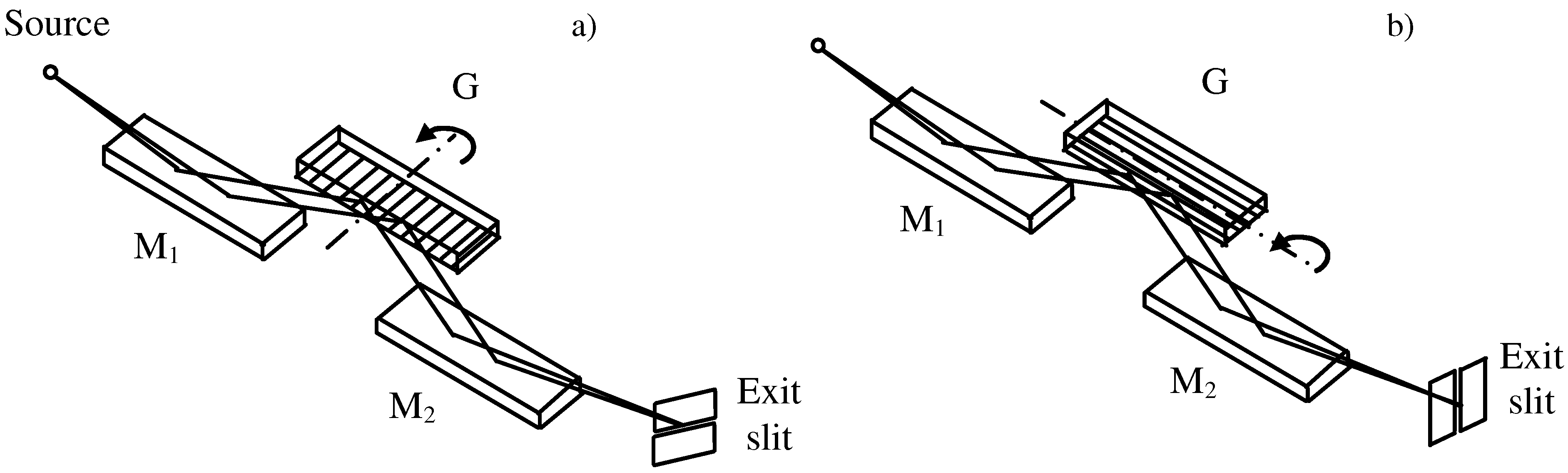
The realization of monochromators for ultrashort pulses introduces an additional and essential parameter to be considered in the comparisons of the two configurations, namely the effect of the grating geometry on the pulse-front tilt. Since the gratings for OPM monochromators are operated in parallel light, we will compare the two configurations with plane gratings, as shown in Figure 2.
Figure 2.
Monochromator with plane gratings: (a) CDM; (b) OPM.

The configuration has three optical elements, namely two mirrors and the grating. The first mirror (M1) acts as the collimator, the second mirror (M2) as the condenser. The magnification is in unity to minimize the aberrations, i.e., p = q, where p is the input arm of the collimator, that is, the distance between the entrance source and the center of M1, and q the output arm of the condenser, that is, the distance between the center of M2 and the exit slit. The number of illuminated grooves in the two geometries is, respectively, Nc = 2 D p σc/cosα and No = 2 D p σo, where D is the half-width beam divergence at the input. The half-width pulse-front tilt is ΔτG ≈ ½Nmλc−1, that is:
![Applsci 03 00001 i005]() where ΔτG,c and ΔτG,o refer, respectively, to the CDM and the OPM.
where ΔτG,c and ΔτG,o refer, respectively, to the CDM and the OPM.

The two configurations give the same tilt for σc/cosα = σo. Therefore, once the maximum pulse-front tilt has been fixed, the groove density in the CDM is lower than in the OPM, i.e., σc < σo. The condition to maintain the pulse-front tilt below the input half-width pulse duration Δτ after the diffraction from N grooves is, respectively, ΔτG,c ≤ Δτ and ΔτG,o ≤ Δτ The shorter the time response, the lower the requested groove density, as stated in Equation 5.
Let us suppose that the width of the exit slit, W, is equal to the size of the XUV source, S, as imaged at the output of the monochromator. This is the minimum width that has to be kept to guarantee the complete transmission of the diffracted beam. The OPM does not give any magnification of the source since p = q, therefore, Wo = S. Instead, the source magnification in the CDM is equal to the anamorphic factor of the grating, cosα/cosβ, therefore, Wc = S cosα/cosβ. By using the formula of the grating dispersion, the half-width output bandwidth results:
![Applsci 03 00001 i006]() where Δλc and Δλo refer, respectively, to the CDM and the OPM.
where Δλc and Δλo refer, respectively, to the CDM and the OPM.

By putting together Equations 5 and 6 we finally obtain:
![Applsci 03 00001 i007]() as the minimum spectral bandwidth at the output of a single-grating monochromator with pulse‑front tilt equal to ΔτG. Once the tilt has been defined, the minimum bandwidth at wavelength λ depends on the characteristics of the source, namely the size and the divergence. Equation 7 can be compared to Equation 2 to find the condition when the bandwidth at the output of a monochromator with ΔτGpulse-front tilt is equal to that of a Fourier-limited pulse of duration Δτ, that is:
as the minimum spectral bandwidth at the output of a single-grating monochromator with pulse‑front tilt equal to ΔτG. Once the tilt has been defined, the minimum bandwidth at wavelength λ depends on the characteristics of the source, namely the size and the divergence. Equation 7 can be compared to Equation 2 to find the condition when the bandwidth at the output of a monochromator with ΔτGpulse-front tilt is equal to that of a Fourier-limited pulse of duration Δτ, that is:
![Applsci 03 00001 i008]()


If the condition stated in Equation 8 is verified, the monochromator is defined to be time-preserving, since the minimum bandwidth achievable at the output is almost the same as the bandwidth of a Fourier-limited pulse of a duration equal to the grating pulse-front tilt.
A monochromator for XUV ultrashort pulses is here designed in both the geometries, to outline the main characteristics of the two configurations. HH emission from a Ti:Sa laser is considered, with a half-width divergence of 2 mrad. The entrance and exit arms are assumed to be p = q = 400 mm, that is, a safe distance to operate the first toroidal mirror that is illuminated also by the intense IR generating laser. The interval of operation is the 15-55 nm wavelength band, i.e., between harmonics H15 and H53. We analyze two different temporal regimes: 100 fs or 10 fs half-width pulse-front tilt at the central wavelength of the range of interest, λc = 35 nm. The grating groove density is calculated from Equation 5 and is reported in Table 1. In the case of the CDM, as the included angle increases, the corresponding groove density decreases. In the case of the OPM, the groove density is almost independent from the choice of the altitude and azimuth angles.

Table 1.
Parameters of a plane-grating monochromator with a half-width pulse-front tilt of 10/100 fs at the wavelength λc = 35 nm. The half-width beam section on the grating is 0.8 mm. The grating in the CDM has been assumed to be operated in the external order, i.e., m = −1.
| Classical diffraction mount | Off-plane mount | ||||
|---|---|---|---|---|---|
| Included angle (°) | Groove density (gr/mm) | Blaze angle at 35 nm (°) | Altitude (°) | Groove density (gr/mm) | Blaze angle at 35 nm (°) |
| 100 fs half-width pulse-front tilt at 35 nm (0.11 nm-115 meV bandwidth on a 50-um slit) | 100 fs half-width pulse-front tilt at 35 nm (0.11 nm-115 meV bandwidth on a 50-um slit) | ||||
| 155 | 255 | 1.2 | 4 | 1100 | 16.0 |
| 160 | 210 | 1.2 | 7 | 1100 | 9.1 |
| 165 | 165 | 1.2 | 10 | 1100 | 6.4 |
| 10 fs half-width pulse-front tilt at 35 nm (1.1 nm-1.15 eV resolution on a 50-um slit) | 10 fs half-width pulse-front tilt at 35 nm (0.11 nm-1.15 eV bandwidth on a 50-um slit) | ||||
| 155 | 24 | 0.1 | 4 | 110 | 1.6 |
| 160 | 19 | 0.1 | 7 | 110 | 0.9 |
| 165 | 15 | 0.1 | 10 | 110 | 0.6 |
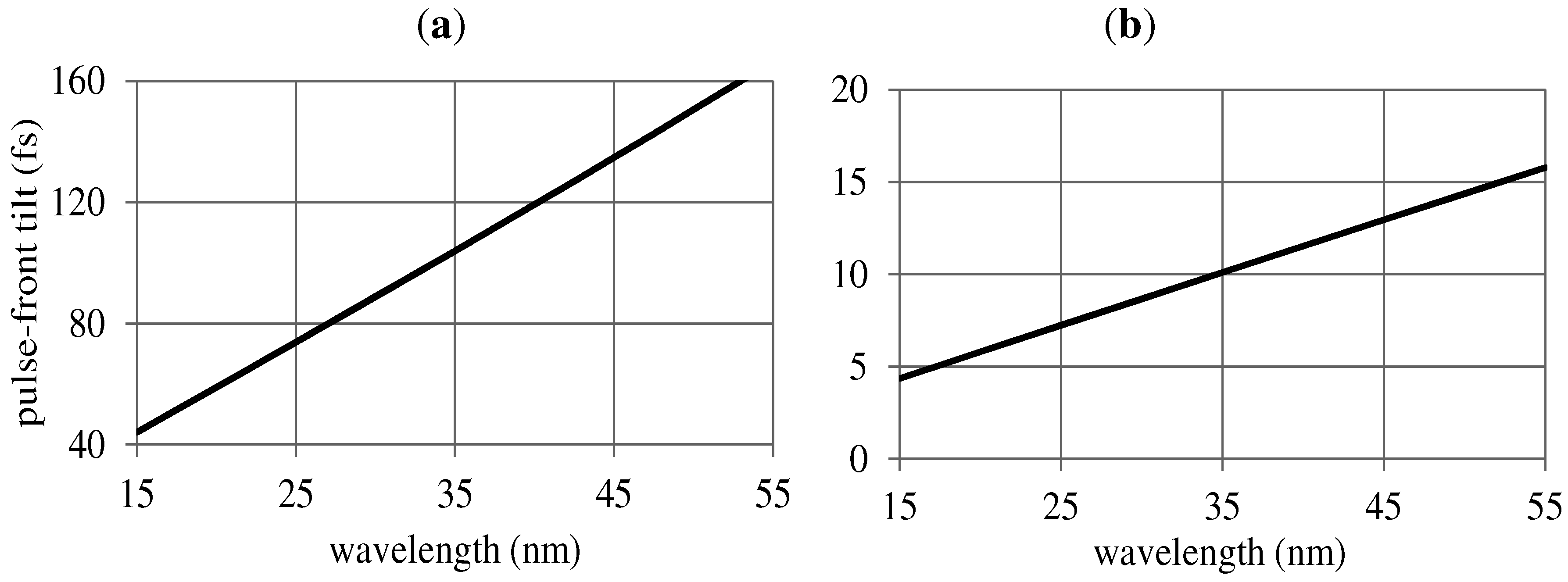
The monochromator pulse-front tilt as a function of the wavelength is shown in Figure 3. For low-resolution configurations, such as those required for ultrashort pulses, the number of illuminated grooves is almost constant with the wavelength in both geometries; consequently, the pulse-front tilt 2 ΔτG = λN/c increases linearly and is almost the same for the two configurations.
Figure 3.
Pulse-front tilt of the monochromator with the parameters listed in Table 1 (a) 100-fs pulse-front tilt at 35 nm; (b) 10-fs pulse-front tilt at 35 nm.
Figure 3.
Pulse-front tilt of the monochromator with the parameters listed in Table 1 (a) 100-fs pulse-front tilt at 35 nm; (b) 10-fs pulse-front tilt at 35 nm.

The grating efficiency curves, as resulting from simulations, are shown in Figure 4. For saw-tooth profiles, the efficiency is expected to be theoretically high in both configurations. Nevertheless, there are deep differences between the CDM and the OPM when the actual shape of the groove profile is analyzed. In fact, the performances of blazed gratings in the CDM are critically dependent on the actual groove profile. In particular, the unavoidable smoothing of the sharp edges of the actual profile gives a decrease of efficiency with respect to the theoretical values that is more evident for extreme blaze angles, where the realization of an ideal saw-tooth profile is practically unfeasible. Configurations with pulse-front tilt in the range of hundreds of femtoseconds in the CDM require the use of gratings with extremely small blaze angles that are feasible although close to the limit of the present capabilities of manufacturers (≈0.7°). Furthermore, since the realization of an ideal saw-tooth profile at such extreme blaze angles is practically impossible, the actual efficiency of a blazed grating will be lower than the theoretical predictions. An alternative to saw-tooth profiles is the adoption of laminar or sinusoidal profiles that exhibit lower efficiency. On the contrary, the grating efficiency in the OPM is less sensitive to the errors in the saw-tooth profile. Furthermore, the blaze angles required for the gratings used in the OPM are less extreme than the CDM, therefore, the deviation between the ideal and the actual saw-tooth profile is lower. This also contributes to the increase of efficiency with respect to the CDM. All these factors confirm the advantage of the OPM in terms of monochromator efficiency. The comparison is even more favorable to OPM for pulse-front tilts in the range of tens of femtoseconds. In this case, the groove density required for CDM is extremely low and the corresponding blaze angle (≈0.1° in the present example) is practically unfeasible. Laminar profiles have to be adopted, and the resulting efficiency is extremely low. On the contrary, the blazed gratings used in the OPM have parameters within the manufacturing capabilities even for few-femtosecond time responses, as is clear from the data presented in Table 1.
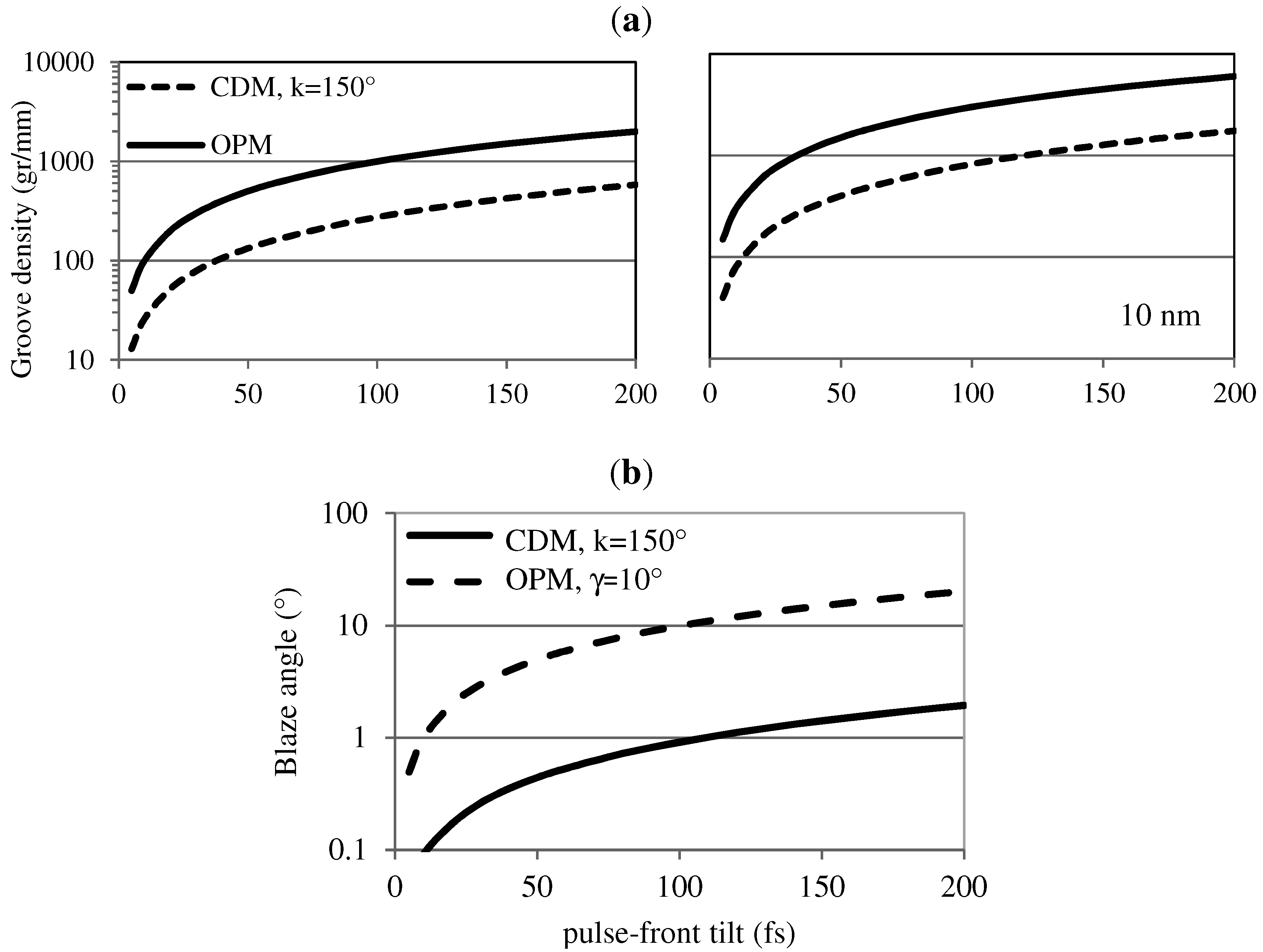
The calculations can be generalized as resumed in Figure 5, where the two geometries are compared for pulse-front tilts in the 5-200 fs interval. For tilts above 100 fs, the CDM requires groove densities of few-to-several hundreds of grooves per millimeter and blaze angles that are feasible with present technologies, while the OPM requires higher groove densities and azimuth angles, therefore introducing a large distortion and rotation of the image after the diffraction [22]. On the contrary, for tilts below 100 fs, the CDM requires gratings with very low groove density and blaze angles that are presently unfeasible, while the OPM requires gratings with standard characteristics even at 5-fs response. As a general claim, the CDM should be preferred for monochromators when a relatively large pulse-front tilt can be tolerated, i.e., 100-200 fs, while the OPM has to be adopted for pulse-front tilts in the 5-50 fs range, providing both high efficiency and ultrafast temporal response.
Figure 4.
Efficiency curve of the gratings with the parameters listed in Table 1: (a) CDM; (b) OPM.
Figure 4.
Efficiency curve of the gratings with the parameters listed in Table 1: (a) CDM; (b) OPM.
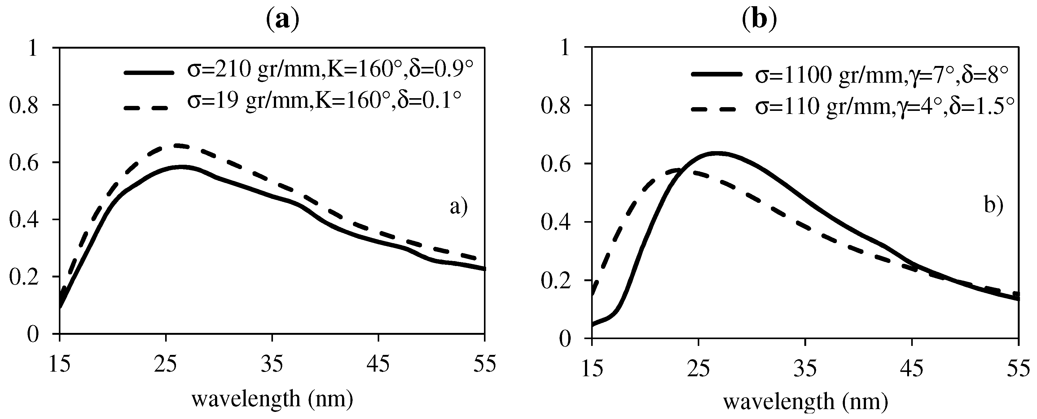
Figure 5.
Grating parameters as a function of the pulse-front tilt for 1-mm half-width beam section: (a) groove density at 30 nm (left) and 10 nm (right); (b) blaze angle.
Figure 5.
Grating parameters as a function of the pulse-front tilt for 1-mm half-width beam section: (a) groove density at 30 nm (left) and 10 nm (right); (b) blaze angle.

The spatial beam profile at focus becomes broader along the dispersion direction, due to the diffraction; therefore, rays at different wavelengths make different optical paths. In addition to the pulse front-tilt, the variation of the group delay within the bandwidth of a single harmonic given by the grating may alter the pulse duration at the output. It can be shown by ray-tracing simulations that this effect is totally negligible when dealing with pulses in the range from few to several tens of femtoseconds, as is the case of single-grating monochromators discussed here. On the contrary, the grating group delay dispersion cannot be neglected for sub-femtosecond pulses, and double-grating monochromators have been designed as XUV attosecond compressors to compensate the intrinsic pulse chirp [23,24].
3. Double-Stage Monochromator for Ultrashort Pulses
The two geometries discussed above can be joined in an innovative design of a monochromator for ultrashort XUV pulses. The instrument has two different and interchangeable diffracting stages both used at grazing incidence, one with the gratings in the CDM and the other in the OPM. The use of two stages gives great flexibility: the OPM stage is used for sub-50 fs time response and low spectral resolution (λ/Δλ ≤ 100) and the CDM stage is used for 100–300 fs time response and medium spectral resolution (λ/Δλ ≥ 500). The design overcomes the limits of the two configurations and presents the advantages of both of them, giving on the same instrument either ultrafast time response with low spectral resolution or longer time response with medium resolution. Furthermore, it has broad tunability and high efficiency.
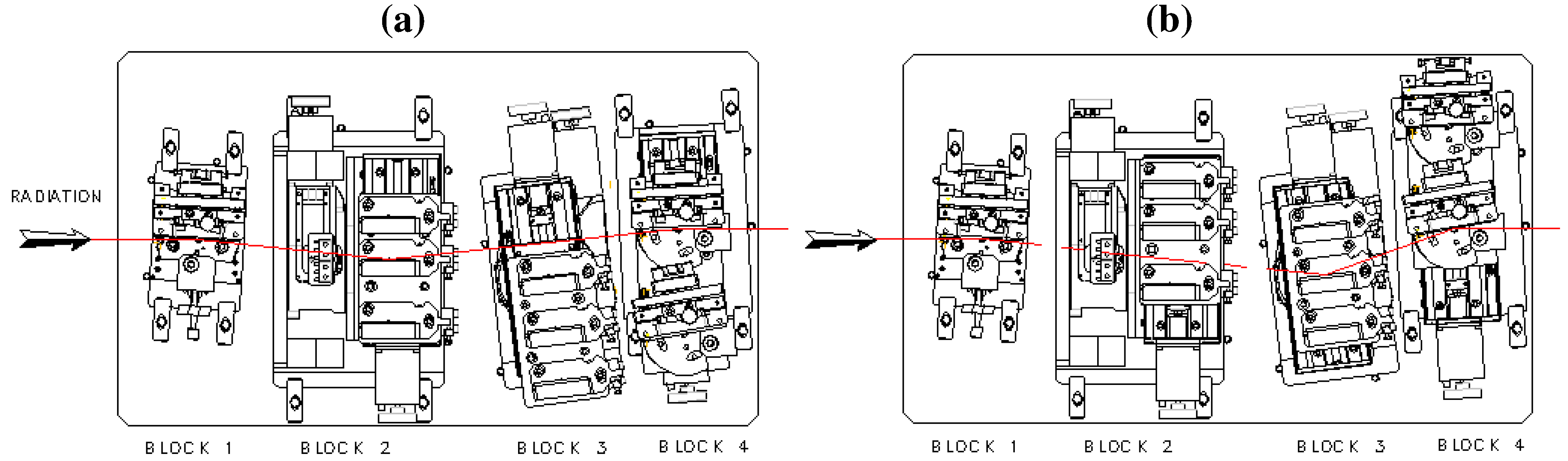
In particular, a monochromator is described here that is being realized for the spectral selection of HHs in the 12–120 nm (100–10 eV) interval. It has several gratings optimized in different intervals within the region of operation and adopts the new proposed design to support both ultrashort temporal response with low resolution and longer response with high resolution. A block diagram is shown in Figure 6. The first block is the fixed toroidal mirror to collimate the light coming from the HH source. The second section consists of three gratings operated in the OPM mounted on a motorized stage to select one of them. The gratings of the second section can be removed from the optical path to use the gratings of the third section. The latter has three gratings operated in the CDM at a constant deviation angle. The forth section has two different toroidal mirrors that can be inserted in the optical path to focus the light on the exit slit: the first one is mounted to intercept the light diffracted by the grating in the OPM, the other is used with the CDM. Finally, the exit slit block has two different variable-width slits: one is mounted vertically for the CDM, the other horizontally for the OPM. The executive drawings to realize the instrument are shown in Figure 7. The parameters of the monochromator are resumed in Table 2. The expected performances are shown in Figure 8.
Figure 6.
Block diagram of the double-stage monochromator: (a) OPM configuration; (b) CDM configuration.
Figure 6.
Block diagram of the double-stage monochromator: (a) OPM configuration; (b) CDM configuration.
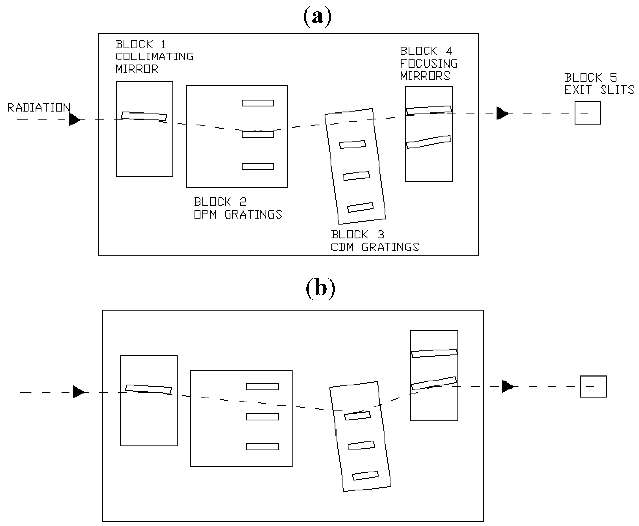
Figure 7.
Executive drawings of the monochromator main chamber; (a) OPM; (b) CDM.

| MIRRORS | GRATINGS | ||
|---|---|---|---|
| BLOCK 1 | Collimating mirror | BLOCK 2 | Off-plane gratings |
| Source-to-mirror | 400 mm | Altitude | 5° |
| Incident angle | 87° | Grating 1 | 30–120 nm 40–10 eV |
| Groove density | 200 gr/mm | ||
| BLOCK 4 | Focusing mirrors | Grating 2 | 20–60 nm 60–20 eV |
| Mirror-to-slit distance | 400 mm | Groove density | 400 gr/mm |
| Mirror 1 | Off-plane geometry | Grating 3 | 12–30 nm 100–40 eV |
| Incident angle | 87° | Groove density | 800 gr/mm |
| Mirror 2 | Classical geometry | ||
| Incident angle | 80° | BLOCK 3 | Classical gratings |
| Deviation angle | 154° | ||
| SLITS | Grating 1 | 30–120 nm 40–10 eV | |
| BLOCK 5 | Horizontal/vertical | Groove density | 300 gr/mm |
| Slit aperture | 20 μm-2 mm | Grating 2 | 20–60 nm 60–20 eV |
| Groove density | 600 gr/mm | ||
| Grating 3 | 12–30 nm 100–40 eV | ||
| Groove density | 1200 gr/mm |
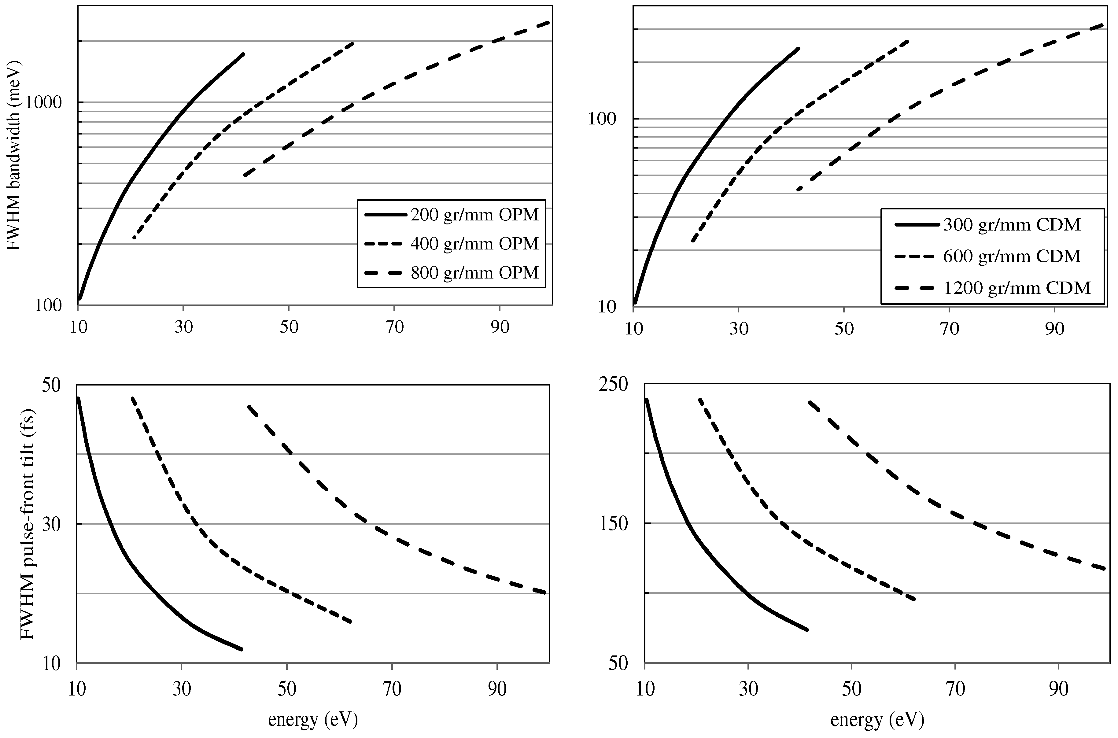
This design allows us to use both the grating geometries with their peculiar characteristics. The OPM stage gives fast temporal response, that is, a pulse-front tilt in the 10–50 fs range, and low resolution, that is, λ/Δλ = E/ΔE ≈ 30–100. The CDM stage gives slower response, that is, a pulse-front tilt in the 70–250 fs range, and higher resolution, that is, λ/Δλ ≈ 250–1000. The OPM stage is used to select the whole bandwidth of a single harmonic for ultrafast pump-probe experiments, while the CDM stage is used to increase the spectral purity of the source beyond the limit given by the bandwidth of the single harmonic, at the price of lower photon flux and longer temporal response.
Let us consider a source size S = 30 μm with half-width divergence D = 1.5 mrad, which are typical parameters in the case of HH generation with low-energy laser pulses. The monochromator is time-preserving at λ = 90 nm (≈9th harmonic), i.e., the bandwidth on a slit of width Wo = S (OPM) and Wc = S cosα/cosβ (CDM) is almost the same as a Fourier-limited pulse of duration equal to the grating pulse-front tilt. At wavelength lower than 90 nm, the monochromator bandwidth is wider than the corresponding Fourier limit.
Figure 8.
Bandwidth and pulse-front tilt. The bandwidth has been calculated on a 100-μm slit; the pulse-front tilt has been calculated with a half-width beam divergence of 1.5 mrad.
Figure 8.
Bandwidth and pulse-front tilt. The bandwidth has been calculated on a 100-μm slit; the pulse-front tilt has been calculated with a half-width beam divergence of 1.5 mrad.

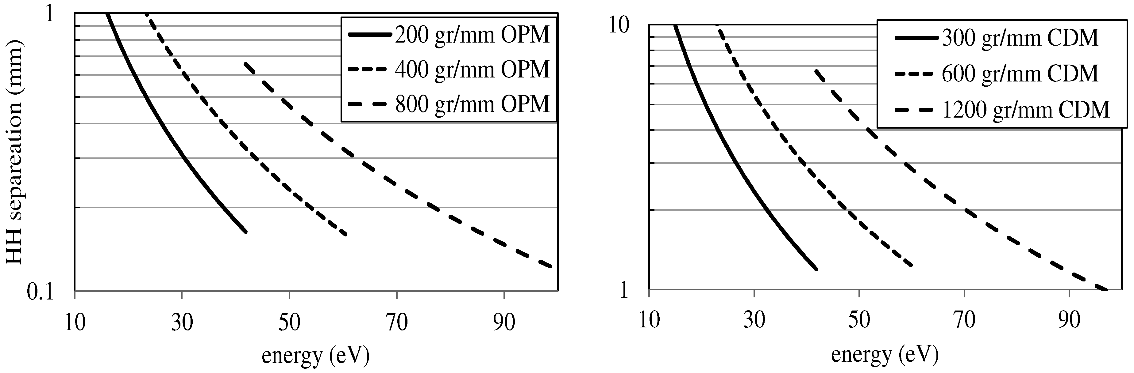
The separation between neighboring harmonics on the focal plane depends on the grating dispersion and is shown in Figure 9. For the CDM, the separation is in the range from few to several mm, due to the high grating dispersion. For the OPM, the separation is definitely smaller, but larger than the typical width of the slit. Obviously, the smaller the dispersion, the smaller the separation angle and the distance between consecutive harmonics. The small separation between harmonics has to be taken into account when using the OPM, since the neighboring orders might still produce noise in photoelectron and ionization spectroscopy, due to the grating scattering.
Figure 9.
Separation between neighboring harmonics at the monochromator exit slit.
4. Conclusions
The pulse-front tilt of single-grating monochromators for XUV ultrashort pulses has been analyzed. Two different grating configurations have been compared: the classical diffraction mount and the off-plane mount. The two geometries have been joined in an innovative design of a monochromator with two interchangeable diffracting stages both used at grazing incidence. The OPM stage is used for sub‑50 fs time response and low spectral resolution; the CDM stage for 100–200 fs time response and higher spectral resolution. The design overcomes the limits of the two single configurations, giving great flexibility on the same instrument, that is, both ultrafast time response with low spectral resolution and longer response with higher resolution.
Acknowledgment
This work has been partially supported by the CITIUS Strategic Project of the Italian-Slovenian Cross-border Cooperation Program 2007-2013.
Conflict of Interest
The authors declare no conflict of interest.
References
- Diels, J.C.; Rudolph, W. Ultrashort Laser Pulse Phenomena, 2nd ed; Elsevier: London, UK, 2006; pp. 277-394, 531-555. [Google Scholar]
- Jaeglè, P. Coherent Sources of XUV Radiation; Springer: New York, NY, USA, 2006; pp. 277–344. [Google Scholar]
- Chang, Z.; Rundquist, A.; Wang, H.; Murnane, M.M.; Kapteyn, H.C. Generation of coherent soft-X rays at 2.7 nm using high harmonics. Phys. Rev. Lett. 1997, 79, 2967–2970. [Google Scholar] [CrossRef]
- Spielmann, C.; Burnett, N.H.; Sartania, S.; Koppitsch, R.; Schnuerer, M.; Kan, C.; Lenzner, M.; Wobrauschek, P.; Krausz, F. Generation of coherent X-rays in the water-window using 5-femtosecond laser pulse. Science 1997, 278, 661–664. [Google Scholar] [CrossRef]
- Corkum, P.B.; Krausz, F. Attosecond science. Nat. Phys. 2007, 3, 381–387. [Google Scholar] [CrossRef]
- Sansone, G.; Poletto, L.; Nisoli, M. High-energy attosecond light sources. Nat. Photonics 2011, 5, 655–663. [Google Scholar] [CrossRef]
- Free-Electron Laser FLASH. Available online: http://flash.desy.de/ (accessed on 12 November 2012).
- SACLA (XFEL). Available online: http://xfel.riken.jp/eng/ (accessed on 12 November 2012).
- LCLS-Linac Coherent Light Source. Available online: http://lcls.slac.stanford.edu/ (accessed on 12 November 2012).
- Martins, M.; Wellhöfer, M.; Hoeft, J.T.; Wurth, W.; Feldhaus, J.; Follath, R. Monochromator beamline for FLASH. Rev. Sci. Instrum. 2006, 77, 115108. [Google Scholar] [CrossRef]
- Poletto, L.; Villoresi, P. Time-compensated monochromator in the off-plane mount for extreme-ultraviolet ultrashort pulses. Appl. Opt. 2006, 45, 8577–8585. [Google Scholar] [CrossRef]
- Poletto, L.; Villoresi, P.; Frassetto, F.; Calegari, F.; Ferrari, F.; Lucchini, M.; Sansone, G.; Nisoli, M. Time-delay compensated monochromator for the spectral selection of extreme-ultraviolet high-order laser harmonics. Rev. Sci. Instrum. 2009, 80, 123109. [Google Scholar] [CrossRef]
- Ito, M.; Kataoka, Y.; Okamoto, T.; Yamashita, M.; Sekikawa, T. Spatiotemporal characterization of single-order high harmonic pulses from time-compensated toroidal-grating monochromator. Opt. Express 2010, 18, 6071–6078. [Google Scholar] [CrossRef]
- Igarashi, H.; Makida, A.; Ito, M.; Sekikawa, T. Pulse compression of phase-matched high harmonic pulses from a time-delay compensated monochromator. Opt. Express 2012, 20, 3725–3732. [Google Scholar] [CrossRef]
- Poletto, L.; Villoresi, P.; Benedetti, E.; Ferrari, F.; Sansone, G.; Stagira, S.; Nisoli, M. Intense femtosecond extreme ultraviolet pulses by using a time-delay compensated monochromator. Opt. Lett. 2007, 32, 2897–2899. [Google Scholar] [CrossRef]
- Poletto, L.; Frassetto, F. Time-preserving monochromators for ultrafast extreme-ultraviolet pulses. Appl. Opt. 2010, 49, 5465–5473. [Google Scholar] [CrossRef]
- Neviere, M.; Maystre, D.; Hunter, W.R. On the use of classical and conical diffraction mountings for XUV gratings. J. Opt. Soc. Am. 1978, 68, 1106–1113. [Google Scholar] [CrossRef]
- Vincent, P.; Neviere, M.; Maystre, D. X-ray gartings: The GMS mount. Appl. Opt. 1979, 18, 1780–1783. [Google Scholar] [CrossRef]
- Pascolini, M.; Bonora, S.; Giglia, A.; Mahne, N.; Nannarone, S.; Poletto, L. Gratings in the conical diffraction mounting for an EUV time-delay compensated monochromator. Appl. Opt. 2006, 45, 3253–3562. [Google Scholar] [CrossRef]
- Werner, W.; Visser, H. X-ray monochromator designs based on extreme off-plane grating mountings. Appl. Opt. 1981, 20, 487–492. [Google Scholar] [CrossRef]
- Frassetto, F.; Cacho, C.; Froud, C.A.; Turcu, I.C.E.; Villoresi, P.; Bryan, W.A.; Springate, E.; Poletto, L. Grating monochromator for extreme-ultraviolet ultrashort pulses. Opt. Express 2011, 19, 19169–19181. [Google Scholar] [CrossRef] [PubMed]
- Poletto, L.; Frassetto, F. Design of high-resolution grazing-incidence echelle monochromators. Appl. Opt. 2009, 48, 5363–5370. [Google Scholar] [CrossRef]
- Poletto, L.; Frassetto, F.; Villoresi, P. Optical concept of a compressor for XUV pulses in the attosecond domain. Opt. Express 2008, 16, 6652–6667. [Google Scholar] [CrossRef]
- Mero, M.; Frassetto, F.; Villoresi, P.; Poletto, L.; Variju, K. Compression methods for XUV attosecond pulses. Opt. Express 2011, 19, 23420–23428. [Google Scholar] [CrossRef] [PubMed]
© 2013 by the authors; licensee MDPI, Basel, Switzerland. This article is an open-access article distributed under the terms and conditions of the Creative Commons Attribution license (http://creativecommons.org/licenses/by/3.0/).
Share and Cite
MDPI and ACS Style
Poletto, L.; Frassetto, F. Single-Grating Monochromators for Extreme-Ultraviolet Ultrashort Pulses. Appl. Sci. 2013, 3, 1-13. https://doi.org/10.3390/app3010001
AMA Style
Poletto L, Frassetto F. Single-Grating Monochromators for Extreme-Ultraviolet Ultrashort Pulses. Applied Sciences. 2013; 3(1):1-13. https://doi.org/10.3390/app3010001
Chicago/Turabian StylePoletto, Luca, and Fabio Frassetto. 2013. "Single-Grating Monochromators for Extreme-Ultraviolet Ultrashort Pulses" Applied Sciences 3, no. 1: 1-13. https://doi.org/10.3390/app3010001