Review

Ultra-Intense, High Spatio-Temporal Quality Petawatt-Class Laser System and Applications

by
Hiromitsu Kiriyama
1,*,
Takuya Shimomura
1,
Michiaki Mori
1,
Yoshiki Nakai
1,
Manabu Tanoue
1,
Shuji Kondo
1,
Shuhei Kanazawa
1,
Alexander S. Pirozhkov
1,
Timur Z. Esirkepov
1,
Yukio Hayashi
1,
Koichi Ogura
1,
Hideyuki Kotaki
1,
Masayuki Suzuki
1,
Izuru Daito
1,
Hajime Okada
1,
Atsushi Kosuge
1,
Yuji Fukuda
1,
Mamiko Nishiuchi
1,
Masaki Kando
1,
Sergei V. Bulanov
1,
Keisuke Nagashima
1,
Mitsuru Yamagiwa
1,
Kiminori Kondo
1,
Akira Sugiyama
1,
Paul R. Bolton
1,
Shinichi Matsuoka
2 and
Hirofumi Kan
2
add Show full author list remove Hide full author list
1
Kansai Photon Science Institute, Japan Atomic Energy Agency, 8-1-7 Umemidai, Kizugawa, Kyoto 619-0215, Japan
2
Development Bureau, Hamamatsu Photonics K. K., 5000 Hirakuchi, Hamakitaku, Hamamatsu-city, Shizuoka 434-8601, Japan
*
Author to whom correspondence should be addressed.
Appl. Sci. 2013, 3(1), 214-250; https://doi.org/10.3390/app3010214
Submission received: 10 December 2012 / Revised: 15 February 2013 / Accepted: 19 February 2013 / Published: 7 March 2013
(This article belongs to the Special Issue Ultraintense Ultrashort Pulse Lasers)

Abstract

:
This paper reviews techniques for improving the temporal contrast and spatial beam quality in an ultra-intense laser system that is based on chirped-pulse amplification (CPA). We describe the design, performance, and characterization of our laser system, which has the potential for achieving a peak power of 600 TW. We also describe applications of the laser system in the relativistically dominant regime of laser-matter interactions and discuss a compact, high efficiency diode-pumped laser system.

1. Introduction

Remarkable progress in recent years with the chirped-pulse amplification (CPA) technique [1] provides great opportunities for experimental study of the behavior of matter in ultrahigh electromagnetic fields in small-scale laboratories [2,3]. Recently, much effort in CPA laser development has been expended towards achieving high intensities such as the 100 TW or even petawatt (PW) power level [4,5,6,7,8,9,10,11,12,13]. Consequently, high intensity laser-matter interaction studies can now be done with focused peak intensities up to 1020 W/cm2 or even to 1022 W/cm2 [7,11,12]. Currently, the development of high power femtosecond laser system having a 200 PW level is being pursued through European Extreme Light Infrastructure (ELI) project [13]. This progress in high-field science gives rise to the birth of new applications and breakthroughs which include relativistic particle acceleration [14,15,16,17,18,19,20], bright X-ray source generation [21,22,23,24,25,26,27], and nuclear activation [28,29].
In order to reach these intensities, great efforts have been directed to increasing the pulse energy and reducing the pulse duration. For many experiments increased peak intensities require a commensurate improvement in temporal contrast. Here, the temporal contrast (referred to henceforth as simply contrast) is taken to be the ratio of the peak intensity of the main pulse to the intensity of the amplified spontaneous emission (ASE) background and has values much greater than one. The temporal contrast is a critical characteristic of femtosecond high intensity laser pulses for many experiments where it is important to avoid any modification of the target, such as pre-plasma formation, before arrival of the main femtosecond laser pulse [30,31]. For example, at peak intensities of 1021 to 1022 W/cm2 and contrast in the range 106–108 the prepulse intensity level (and duration) is above threshold for pre-plasma formation on a solid target. In this low contrast case the ASE alters the physical condition of the target for the main intense pulse. In order to avoid the preplasma formation before the main femtosecond pulse of such high intensity arrives, it is essential to increase the contrast level to 1012 or more. The use of high contrast pulses for interaction of high intensity lasers with solid targets is of primary importance for a number of experiments.
Specifically, in the last several years, multi-MeV ion acceleration from laser-irradiated thin target foils is an area that has received considerable interest and has been widely examined both experimentally and theoretically. When an ultra-intense laser pulse is incident on a thin target foil, protons, arising from hydrogenated contamination layers on the surface of the foil, are accelerated owing to electric-field formation. Experimental data and particle in cell (PIC) simulations of laser-acceleration of ions suggest the maximum proton energy increases significantly as the target thickness is reduced for sufficiently high laser intensity and contrast [14,15,31]. Because contrast is crucial for accessing high field physics in desired targets it has become a major issue, and is today under serious investigation throughout the world.
Various pulse cleaning techniques have been investigated to suppress the ASE for improving the contrast. These include using cross-polarized wave (XPW) generation [32,33], the saturable absorber [34,35], the plasma mirror [36,37], self-diffraction in bulk Kerr media [38], and optical parametric amplification (OPA) [9]. XPW generation can provide good contrast of greater than 1010 at the multiterawatt power level. Although the XPW technique can accommodate input intensities up to TW/cm2, the efficiency of this technique is limited to the range of 10%–20% [39]. The plasma mirror is a simpler, more robust, and more effective technique that can be applied at the full compressed pulse energy focused to high fluence levels for which there are consequently no additional downstream contributions to ASE. Therefore the plasma mirror is used in many laboratories, and significant improvement in the contrast to levels much greater than 1010 have been reported [37]. However, in contrast to the XPW or saturable absorber methods, this also means that its efficiency, which is typically 50%–70% for the single stage implementation, is not recoverable downstream. It is challenge to implement this technique at high repetition rates because each targeted area is used once for each laser shot. The spatial beam qualities such as focusability and stability are also very sensitive to variation of the fluence on the plasma mirror [40,41]. More recently, self-diffraction in a bulk Kerr medium has been investigated and demonstrated contrast improvement by four orders of magnitude. However, the diffusive light from the Kerr medium and the angular dispersion are obstacles to this new contrast enhancement technique. If an OPA front end is utilized, the achieved contrast is at the 1010 level. Optical parametric chirped-pulse amplification (OPCPA) [42,43] is becoming increasingly popular as a front-end preamplifier system that can significantly improve contrast, but is demonstrated only for the front-end of PW-class Nd:glass laser system for fusion research [44,45,46,47] upstream of an amplifier chain and where the pulse energy is much lower. The use of an OPCPA preamplifier in a petawatt-class high-intensity Ti:sapphire laser has not been demonstrated.
Homogeneous flat-top circular profiles with steep edges are needed to pump a large-aperture Ti:sapphire crystal, to enable high beam quality, CPA systems at the petawatt power level. In PW-class systems the flat-top transverse beam profile is required for both amplification efficiency and to guarantee operation below the damage threshold on large aperture Ti:sapphire crystals and large gratings which are typically very expensive optical components in the system. Frequency-doubled large-aperture high-energy Nd:glass green lasers are widely used to pump PW-class laser systems [4,5,7,8,9,10,11]. The flat-top beam profile is required from the pump lasers to maintain acceptable beam quality, reliable damage-free operation and to increase amplification efficiency. However, the direct output beam of the Nd:glass laser system typically exhibits a poor (unacceptable) spatial beam profile which can lead to local hot spots (high intensity). These hot spots can induce intensity modulations and enhance parasitic transverse lasing. It is necessary to control the green pump profile to achieve a mandatory flat-top distribution. Some methods for maintaining the flat-top profile of Nd:glass green pump lasers have been investigated such as image relaying (with spatial filtering in some cases) [4,5,7] and the use of a microlens array [48]. The shaping the glass pump beam profile with a microlens array homogenizing system has been demonstrated [48]. The working principle of this technique is to divide the incident beam into many sub-apertures which are all expanded onto the same area in the so-called target plane which lies inside the laser crystal. The resulting profile in the target plane, however, can exhibit the Talbot effect, which might result in low amplification efficiency due to low beam overlap efficiency. The utilization of diffractive optical elements (DOE) has been proposed for profile homogenization. However, to date, there have been only a limited number of reports on beam homogenization of high-energy lasers using a DOE [49].
The development of energetic, intense laser systems with adequately high temporal contrast and high spatial quality remains an important challenge. The development of such laser sources will bring us closer to the realization of compact energetic proton, electron, or X-ray sources that can potentially revolutionize medical and industrial science and technology.
In this paper, we describe a temporally and spatially high quality petawatt-class OPCPA/Ti:sapphire hybrid laser system (which we have named J-KAREN). The ~1012 contrast has been achieved using our J-KAREN laser system [11]. Injecting “cleaned” seed pulses into the OPCPA preamplifier at higher energy (microjoules) allows the pump fluence to be lowered while still reaching the same broadband output energy. This low-gain OPCPA operation reduces the parametric fluorescence, thereby enhancing the contrast. The introduction of an extra saturable absorber after the OPCPA preamplifier results in further contrast improvement [50] without significant parameter changes in the system. Moreover, an actively controlled acousto-optic programmable dispersive filter (AOPDF) is used to precompensate the spectral phase changes due to propagation, to enhance the contrast around the main pulse [51], and to precisely control dispersion to obtain the amplified pulse duration of shorter than 30 fs. High contrast of 1.4 × 10¹² has been obtained at 70 TW without a plasma mirror. The uncompressed pulse energy of 28 J is achieved, indicating the potential for reaching the peak powers near 600 TW. Because state-of-the-art PW-class CPA laser facilities use Ti:sapphire amplifiers, temporal contrast is in the approximate range, 106–1010. Specifically, the use of double CPA with an OPCPA preamplifier and Ti:sapphire main amplifier leads to extremely high temporal contrast in the petawatt-class power range. An efficient beam homogenization scheme using DOEs produces a broadband amplified flat-topped output with a 70% filling factor. To the best of our knowledge, this is the first petawatt-class hybrid laser system which combines both Ti:sapphire CPA and OPCPA techniques, and the first to evaluate the filling factor values for the spatial profile for both pump and amplified broadband beams with DOEs. The performance of this high intensity laser system will enable many high field applications. We discuss applications with J-KAREN laser system in relativistic dominated regime of laser-matter interactions such as laser accelerated ions and electrons, XUV electromagnetic wave generation, hard X-ray generation, soft x-ray harmonic comb generation, radiation biology, and prospects of high field science experiments. We also describe compact, high efficiency diode-pumped laser systems such as Yb:YAG laser CPA laser and new Nd-doped ceramic laser.

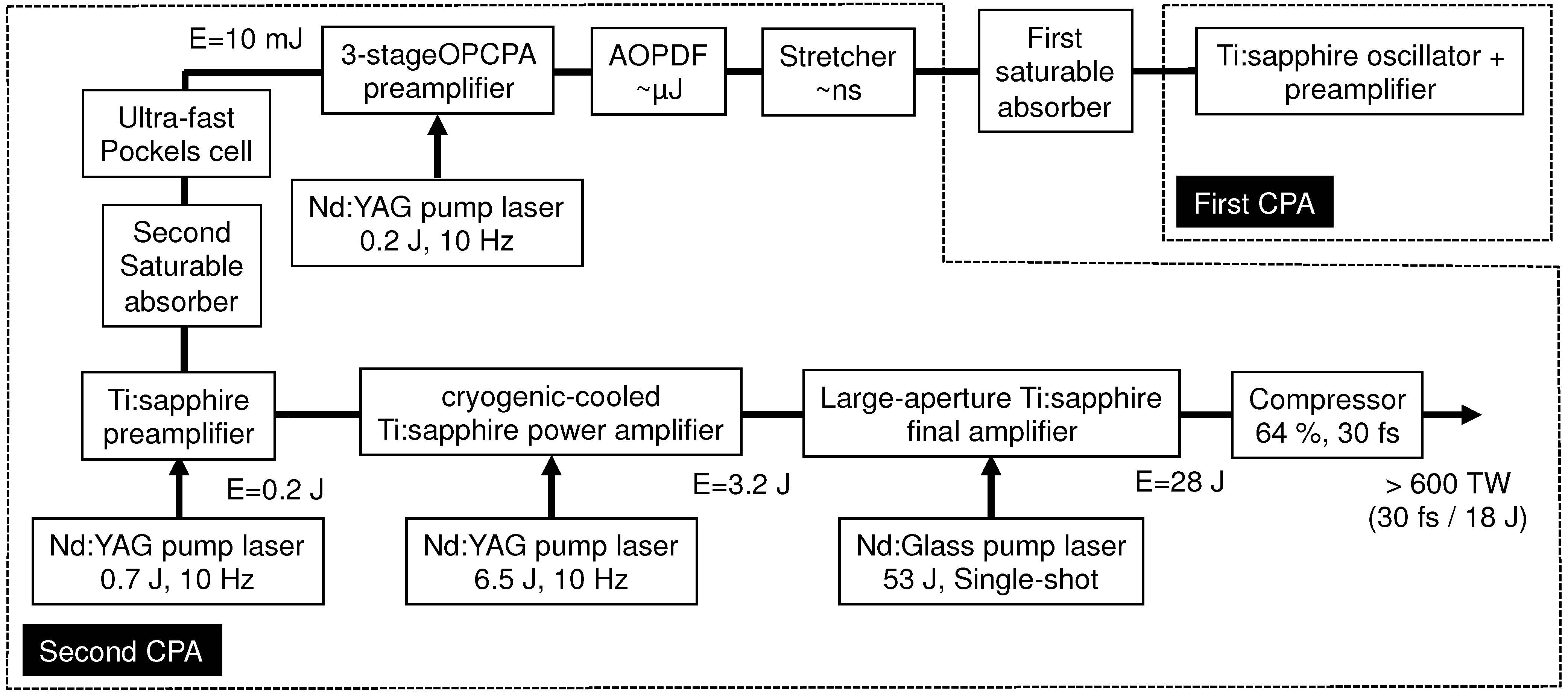
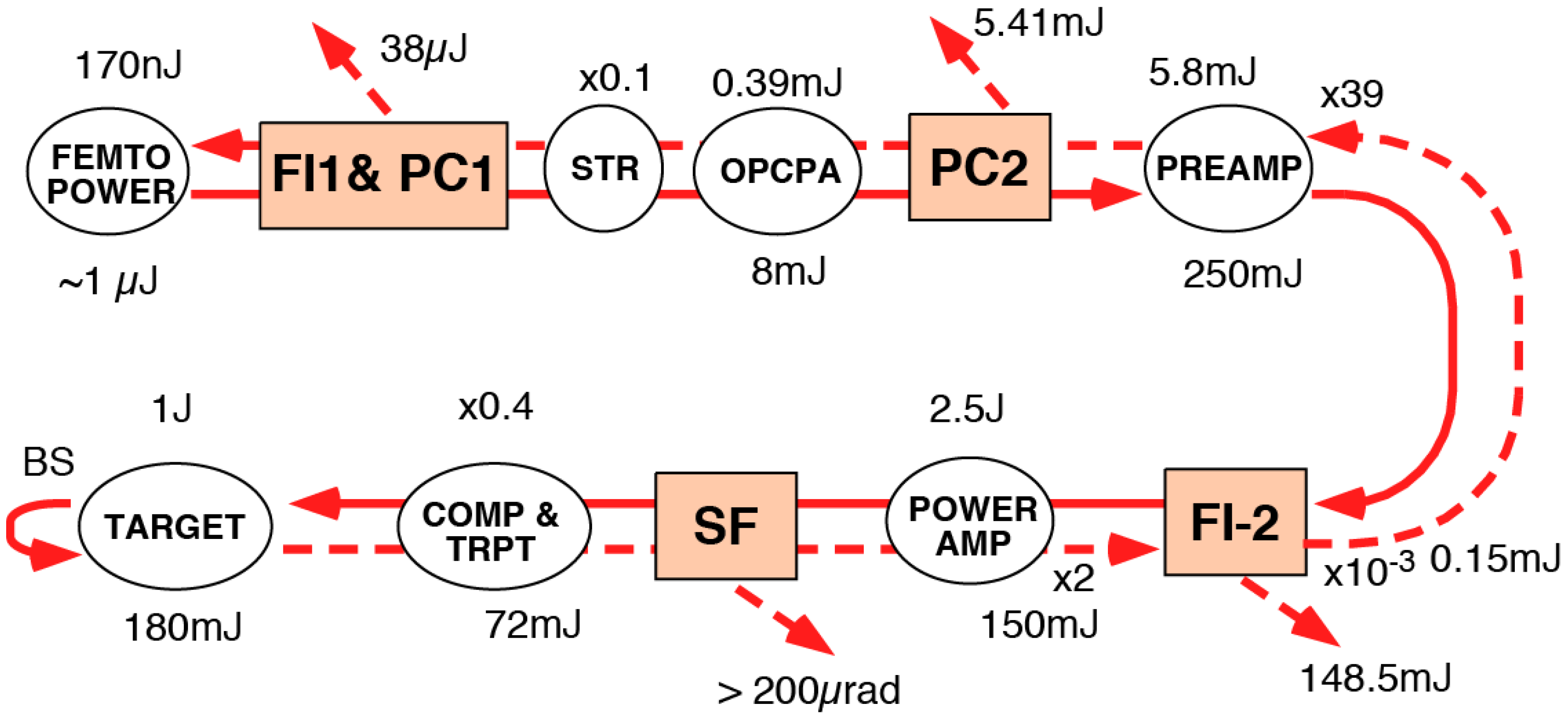
2. Design and Performance of Ultra-Intense “J-KAREN” Laser System

The J-KAREN laser is the flagship laser at Kansai Photon Science Institute (KPSI) of Japan Atomic Energy Agency (JAEA). The laser features a number of innovations which make it unique. In particular, the double CPA scheme, OPCPA preamplifier, and two saturable absorbers improving the contrast; cryogenically cooling of the power amplifier removing the thermal lensing; diffractive optics drastically improving the beam profile of pumping beams; index-matching liquid around the large Ti:Sapphire crystal removing parasiting lasing; automatic beam alignment systems ensuring the stability; extremely high power, beam quality, and contrast; possibility of daily operation during long experimental campaigns; and more. All these made possible several discoveries and pioneering experiments performed with the J-KAREN laser, as described in the Section 3.
A schematic of the J-KAREN laser system is shown in Figure 1. The system consists of two successive CPA stages linked by a saturable absorber, which acts as a nonlinear temporal filter. The first CPA stage consists of an oscillator, a stretcher, a nine-pass amplifier and a compressor. The second CPA stage consists of a stretcher (using 1480 grooves/mm gratings), a three-stage OPCPA preamplifier, a four-pass Ti:sapphire preamplifier, a four-pass cryogenically cooled Ti:sapphire power amplifier, a three-pass Ti: sapphire final booster amplifier and a compressor that consists of four 1480 grooves/mm gratings.
Figure 1. Schematics of the J-KAREN laser system.
Applsci 03 00214 g001

2.1. Front-End System

In the first CPA stage, we use a compact commercial Ti:sapphire CPA laser system (Femtolasers, Femtopower Compact Pro). This system produces submillijoule, sub-30 fs pulses at a repetition rate of 1 kHz. Part of the ASE pedestal on these femtosecond pulses from the first CPA system is initially removed by transmission through a first saturable absorber. We avoid thermally induced damage to the saturable absorber by operating a Pockels cell at a 10 Hz repetition rate in the nine-pass amplifier, which then transmits pulses to the absorber and on to the second CPA stage of J-KAREN at only 10 Hz. The remaining pulses at 990 Hz will be directed to other experimental areas. The pulses are transmitted through the first 3 mm thick saturable absorber with about 25% efficiency (about 75% energy loss) at an incident intensity of 0.2 TW/cm2. The material of our saturable absorbers is the colored glass filter (RG850, Newport). Because transmission is intensity dependent, the saturable absorber also acts as a spatial filter, and the spatial profile quality is therefore also improved. It is important to note that the main laser pulses must be compressed to femtosecond durations at the input of the saturable absorber in order to remove the unwanted ASE portion (hence the need for a double-CPA architecture). The challenge is to generate the high-energy, cleaned femtosecond laser pulses for the second CPA stage. By injecting high-energy cleaned seed pulses into the second CPA stage, the amplification ratio (gain) in the second is kept low and, therefore, the final ASE level can be suppressed.

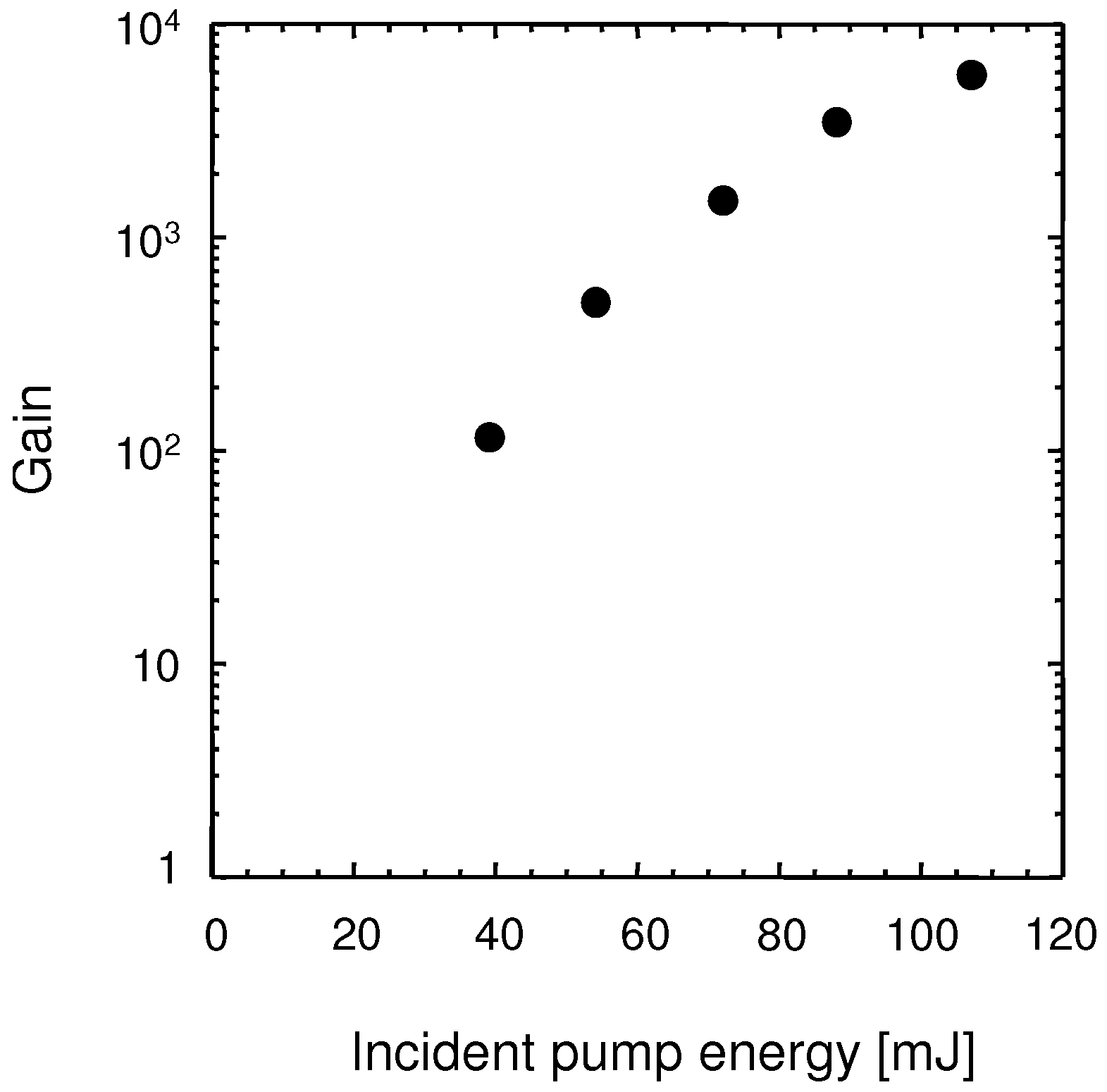
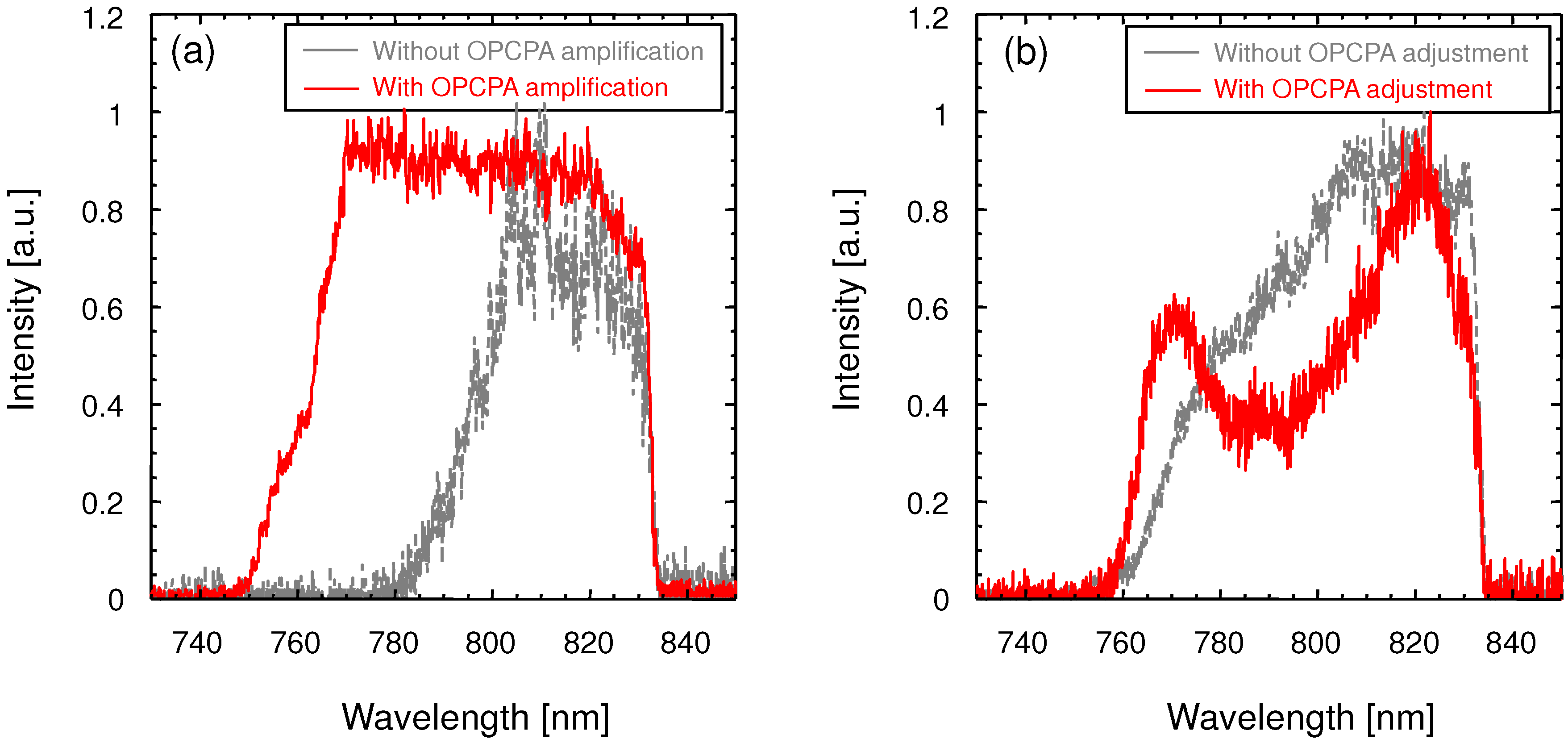
2.2. OPCPA Preamplifier

In the second CPA stage, the OPCPA preamplifier replaces the more conventional regenerative amplifier in order to maintain the high contrast and broad spectral bandwidth. The cleaned pulses of higher energy are temporally stretched (chirped) in a grating-based all-reflective Öffner stretcher [52] is composed of gratings with a groove density of 1480 grooves/mm, a 1000 mm radius of curvature concave mirror (320 mm diameter), a −500 mm radius of curvature convex mirror (160 mm long, 15 mm high), and a roof mirror. Immediately downstream of the stretcher, the AOPDF controls spectral phase prior to further amplification. A Faraday isolator and the Pockels cell with a pair of polarizers provide needed optical isolation between the oscillator and the amplifiers. The stretched pulses with duration ~1 ns and energy ~1.5 μJ are introduced into the three-stage OPCPA preamplifier, consisting of three type I β-barium borate (BBO) crystals. Parametric fluorescence is known to degrade contrast in the high-gain regime where seed energies are low (of the order of nanojoules) and pump intensities are high. Therefore, contrast improvement can be achieved with higher seed energy levels (~1.5 μJ) and a lower OPCPA gain requirement [53,54,55]. Our OPCPA preamplifier consists of three (BBO) crystals. A BBO crystal is chosen as the nonlinear crystal because of its high effective nonlinear coefficient. The size of the first two crystals is 7 × 7 × 19.5 mm, and that of the third crystal is 7 × 7 × 16 mm. Both antireflection-coated (AR-coated) crystals are cut at 23.8° to maximize the gain bandwidth and to facilitate type I noncollinear angular phase matching with an external angle between the seed and the pump of 3.9°. Each crystal is mounted on a precision rotation stage to optimize the angle between the input beams and the crystal. A common pump pulse is used for the OPCPA to reduce the system size and complexity. Each crystal has a 2° wedged output face to suppress intracavity oscillation [11,35,56].
The pump pulses for the OPCPA are generated by the second harmonic of a commercial Q-switched single-longitudinal mode seeded Nd:YAG laser (Spectra-Physics, GCR-150), producing 220 mJ (532 nm) of energy with 5.5 ns (FWHM) )pulse duration at 10 Hz. The output temporal profile is smooth and near-Gaussian and the spatial profile almost a flattop. Pump pulses are relayed to a plane between the three BBO crystals with a vacuum image telescope that precisely matches the pump beam diameter to that of the seed (~4.1 mm at the 1/e2 intensity points).
Figure 2 shows the amplification gain versus pump energy in our OPCPA system. OPCPA gain is measured with a photodiode and a calibrated neutral density filter set. With an energy of 1.5 μJ, the input seed intensity is near 12 kW/cm2. Most OPCPA systems operate with very high gain, of the order of 107–1011 [56,57,58,59,60]. However, our OPCPA provides a maximum gain of only ~6 × 10³ with an incident pump fluence of 0.8 J/cm2 (corresponding to a pump energy of 107 mJ) and amplifies the seed pulses to ~10 mJ. Parametric fluorescence can deteriorate the temporal pulse contrast when using the low seed energy in combination with the high pump intensities that are typical. Temporal pulse contrast can, therefore, be improved by operating the OPCPA in a higher seed energy, low-gain mode. Pump and seed pulses are synchronized in time by a Thales Laser ISEO unit, with a characteristic timing jitter of less than ±0.5 ns in our system. Automatic beam alignment system for seed beam is used to implement beam adjustment to improve long-term stability. We obtain a measured shot-to-shot energy stability over 10 min of ±5% in our OPCPA system. After exiting the OPCPA unit pulses pass through the second saturable absorber and an ultrafast Pockels cell for eliminating the nanosecond ASE pedestal on the OPCPA output to further enhance the contrast. Our Pockels cell (UPC 068, Laysop Ltd.) has a rise time of 150 ps, an aperture of 6 mm in diameter, and the temporal window of 2.5 ns.
Figure 2. Gain from optical parametric chirped-pulse amplification (OPCPA) preamplifier stage versus pump energy.
Applsci 03 00214 g002
Figure 3a displays typical output spectra at the OPCPA preamplifier exit with and without OPCPA amplification. The spectrum with OPCPA amplification, as shown in Figure 3a, exhibits significant broadening by almost a factor of two to reach 70 nm (FWHM). Figure 3b shows the output spectra after the second 1 mm thick saturable absorber with and without OPCPA adjustment. The dashed blue curve in Figure 3b shows the output spectra by just inserting the saturable absorber after OPCPA amplification, as shown in Figure 2a. This extra saturable absorber at the OPCPA exit removes much of the parametric fluorescence and thereby enhances the contrast, but with about 40% transmission efficiency (about 60% energy loss) at an incident intensity of 10 MW/cm2 and a small bandwidth reduction due to the transmittance characteristic of our saturable absorber, as seen in Figure 3b. However, as can be seen from the spectra in Figure 3b, it is possible to obtain shaped and broadened amplified pulse spectra to obtain near 70 nm bandwidth (FWHM) with OPCPA amplification by adjusting pulse timing and phase-matching conditions [56]. Using a saturable absorber is a simple way to remove the ASE, but it can also result in spectral narrowing in CPA systems. Within the OPCPA, altering the phase-match setting makes it possible to tune the central wavelength of the amplified pulse and, therefore, spectral shaping of the amplified pulse in a given spectral range is possible by cascading two BBO crystals working under slightly different phase-match settings. Another significant advantage of the OPCPA system [56,61] is that spectral control can also be achieved by varying the noncollinear pump-signal angle and the amplification pulse timing. The OPCPA output spectrum can also be optimized to better match the gain characteristics of the subsequent amplifiers. Significant changes of spatial profile quality have not been observed with and without the second saturable absorber.
Figure 3. (a) Amplified output spectra after OPCPA preamplifier stage with (solid red curve) and without (dashed gray curve) OPCPA amplification; (b) Amplified output spectra after second saturable absorber with (solid red curve) and without (dashed gray curve) OPCPA adjustment.
Applsci 03 00214 g003

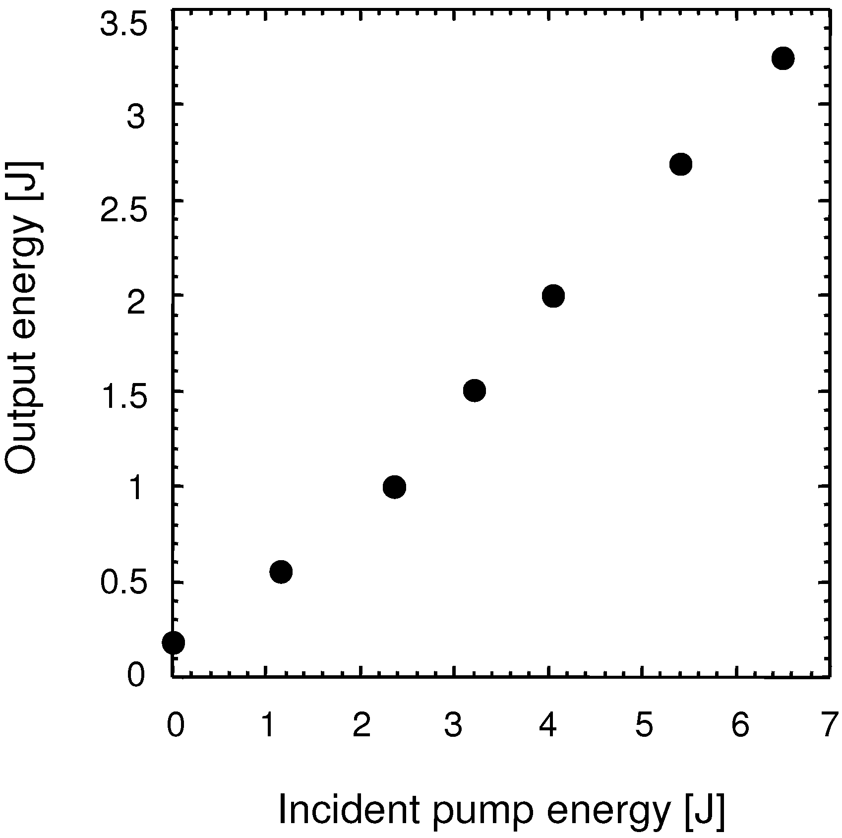
2.3. Cryogenic-Cooled Ti:sapphire Power Amplifier

A conventional four-pass Ti:sapphire preamplifier further amplifies the broadband pulse energy. The preamplifier uses a 20 mm diameter Ti:sapphire crystal pumped by the second harmonic of a commercial Q-switched Nd:YAG laser (Continuum, Powerlite 9010) that delivers ~700 mJ (532 nm) pulse energy at 10 Hz. The pump beam is split into two beams that are relay imaged to opposite faces of the Ti:sapphire crystal. Image relaying is used throughout the optical train to minimize the diffractive effects, maintain beam uniformity, and to optimize coupling efficiency between the pump and the signal beams. Preamplification to a maximum energy ~220 mJ is obtained.
The pump laser also heats the Ti:sapphire crystal. Originating mainly from the difference between the pump and the amplified beam photon energies (quantum defect), heating generates a spatial refractive index gradient in the crystal, which is a source of unwanted thermal lensing of the amplified beam. Thermal lensing in Ti:sapphire gain media can be major problem if unaddressed in preamplifier design. So, in this Ti:sapphire preamplifier, the appropriate beam divergence is introduced (by adjusting the lenses separation in the upstream Galilean beam expander at the OPCPA exit), which matches the thermal focusing power of the Ti:sapphire preamplifier to counteract the thermal lens effect in the crystal. The input seed laser beam diameter is larger than the pump beam diameter. However, thermal focusing reduces the seed beam diameter to a collimated ~6 mm after four-pass amplification. At the Ti:sapphire preamplifier exit, the beam is subsequently up-collimated to an ~18 mm diameter and introduced into the four-pass cryogenically cooled Ti:sapphire power amplifier, which uses a 40 mm diameter AR-coated Ti:sapphire crystal. The power amplifier is pumped at 10 Hz by ~6.5 J of second harmonic energy delivered by six commercial frequency-doubled, Q-switched Nd:YAG lasers (Spectra-Physics, Quanta-Ray Pro-350). All pump lasers are also image relayed to maintain a uniform spatial profile and to prevent damage to optics that can be caused by diffractive effects. As with the preamplifier, high average pump power can induce strong thermal lensing. We implemented cryogenic cooling to increase thermal conductivity, while reducing both refractive index gradient and the thermomechanical stress. Cryogenic cooling results inthermal focal lengths near 4000 m under the maximum pumping condition, rendering thermal lensing insignificant [12,62,63,64].
The output energies from power amplifier are obtained by increasing the pump energy while maintaining the Ti:sapphire crystal temperature at 100 K in the cryogenic chamber. A maximum output energy of over 3.2 J is achieved with an incident pump energy of ~6.5 J as shown in Figure 4. The excellent power stability of less than ±2% is observed over a 1 h interval, which is well in excess of the amplifier thermalization time at the highest pump level. The whole system is highly stable for several hours. The amplified pulse spectrum from the Ti:sapphire amplifier is redshifted due to saturation. As a mitigating measure, the amplifier input spectrum is, therefore, blueshifted by tuning the phase-match setting of the BBO crystals in the OPCPA preamplifier. We obtain the spectral bandwidth of ~50nm from the power amplifier.
Figure 4. Measured output energy from Ti:sapphire power amplifier versus pump energy.
Applsci 03 00214 g004

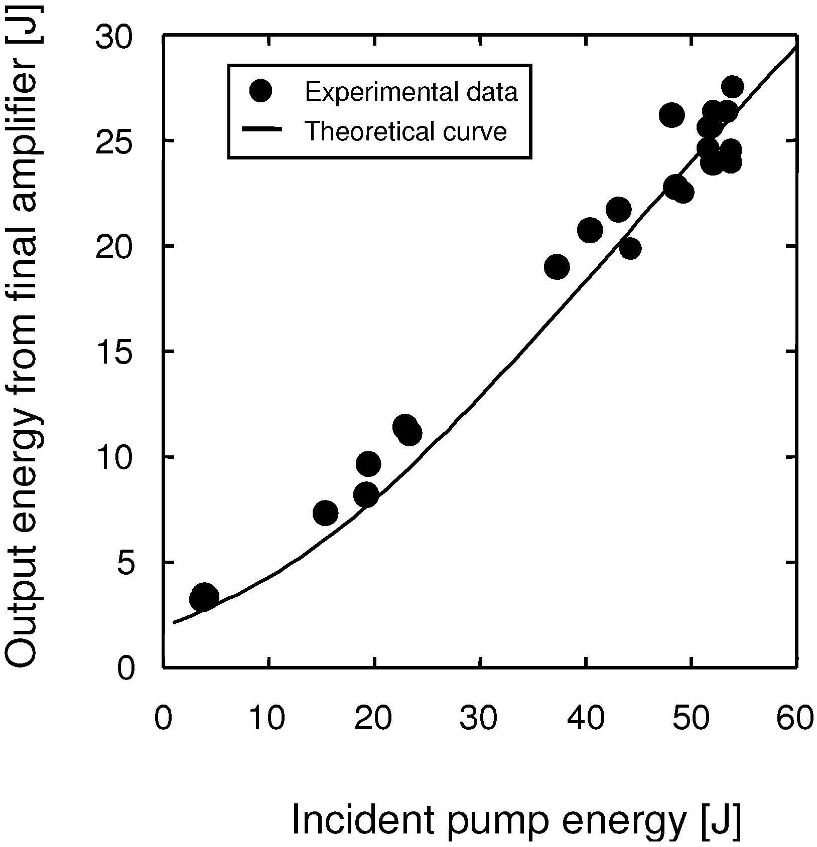
2.4. Large-Aperture Ti:sapphire Final Amplifier

The pulses then undergo further amplification in the final amplifier, which uses a large-aperture 80 mm diameter Ti:sapphire crystal that is pumped with a frequency-doubled large-aperture high-energy glass laser. Our pump laser has single-pass master oscillator power amplifier architecture, operated at a few shots per hour. In the pump system, a long cavity Q-switched Nd:YAG master oscillator generates ~200 mJ pulses of ~28 ns duration (FWHM) at a 1064 nm wavelength, which matches the emission band of the Nd:silicate-glass rod amplifiers. The duration of the oscillator pulse should be as long as possible to enable high-output fluence operation without optical damage. The oscillator output is shaped with a soft aperture to a near flat-top intensity distribution and then preamplified to ~1 J by a 9 mm diameter Nd:YAG rod preamplifier. The pulse energy is further increased in a chain of 16, 25, 45, and 64 mm diameter Nd:glass rod amplifiers to ~180 J. At appropriate locations, spatial filters and optical isolators (a pair of Faraday isolators) are used to suppress reflections that can cause damage upstream along the laser chain.
The 1064 nm output pulses are down collimated to a ~40 mm diameter and are subsequently frequency doubled to 532 nm with two 60 mm × 60 mm Type II KD2PO4 (DKDP) crystals (Cleveland Crystals, Inc., Ohaio, USA). To achieve high conversion efficiency, we have used a quadrature arrangement for second harmonic generation (SHG), in which two nonlinear crystals cut for type II interaction are placed in series but are oriented perpendicular to each other [65,66]. DKDP crystals are chosen because of the easy availability in large sizes. The input and output faces of the crystals are SolGel AR coated for both 532 and 1064 nm laser radiation. In the pump system, the maximum green pulse energy of 96 J is generated with an incident fundamental energy of 177 J at 504 MW/cm2, corresponding to SHG efficiency of 54%. Dichroic mirrors separate the green and unconverted fundamental laser beams. With a half-wave plate and a thin-film polarizer, we generate an energy-balanced pair of green pump pulses from the DKDP crystals to provide similar energies for pumping both sides of the Ti:sapphire crystal.
The two pulses are delivered to the Ti:sapphire crystal using reflective optics, image relaying, and DOEs (SILIOS Technologies). The polarization plane for one side is suitably oriented with respect to the Ti:sapphire crystal using a half-wave plate. We have selected DOEs for beam homogenization because they could produce a circular top-hat profile with sharp edges and they were readily available in the required size [10,49]. The clear aperture of our AR-coated DOEs is 80 mm. Each DOE is divided into about 200 subcells, which are all expanded onto the same area at the target plane that lies in the Ti:sapphire crystal. The eight-level striped pattern corresponding to the engravings in the subcells in 1mm thick fused silica material are specially calculated for our requested shape [67]. The diffraction efficiency of DOE is measured to be 82%. Because of some optical components, such as half-wave plates, dichroic mirrors, thin-film polarizers, reflective optics, and relaying optics [68], the measured transmittance efficiency from the second DKDP to Ti:sapphire crystal, including the DOE efficiency, is 67% in our case. The undiffracted and on-axis focused beams are dumped.
The pulses from power amplifier are up-collimated and enter the three-pass Ti:sapphire final amplifier. The Ti:sapphire crystal is a commercially available disk (Crystal Systems, Inc.) that is 80 mm in diameter and 33 mm thick. The crystal is AR coated on two main surfaces, but not polished on the cylindrical outer surface. To suppress parasitic lasing that is associated with Fresnel reflection from the cylinder inner surface, we have employed a cladding material that consists of refractive index-matched liquid containing a broadband absorbing dye. Its refractive index is 1.76. We found that it bonds readily to the crystal’s outer cylindrical surface. This reduces the reflection coefficient at normal incidence from 7% in the air down to 0.01%. The absorption coefficient at 532 nm for the crystal with the refractive index-matched liquid cladding, for example, is 0.78 ± 0.25 cm−1. This cladding technique might overcome the technical difficulty of the long-term performance of the high-gain amplification and the cladding refreshment for large aperture Ti:sapphire crystals. This technique would enable the J-KAREN amplifiers to increase output energy, repetition rate, and long-term stability in the future. The output energy of the final amplifier with the thermoplastic polymer cladding is shown in Figure 5. Thermal lensing in the final amplifier is insignificant because of the low repetition rate. The maximum output energy of 28 J (uncompressed) is achieved with the incident pump energy below 55 J (an all optical conversion efficiency of greater than 50%). From Figure 5, it is seen that the experimental data are well fitted to Frantz-Nodvik simulation [69].
Figure 5. Measured output energy from Ti:sapphire final amplifier versus pump energy.
Applsci 03 00214 g005

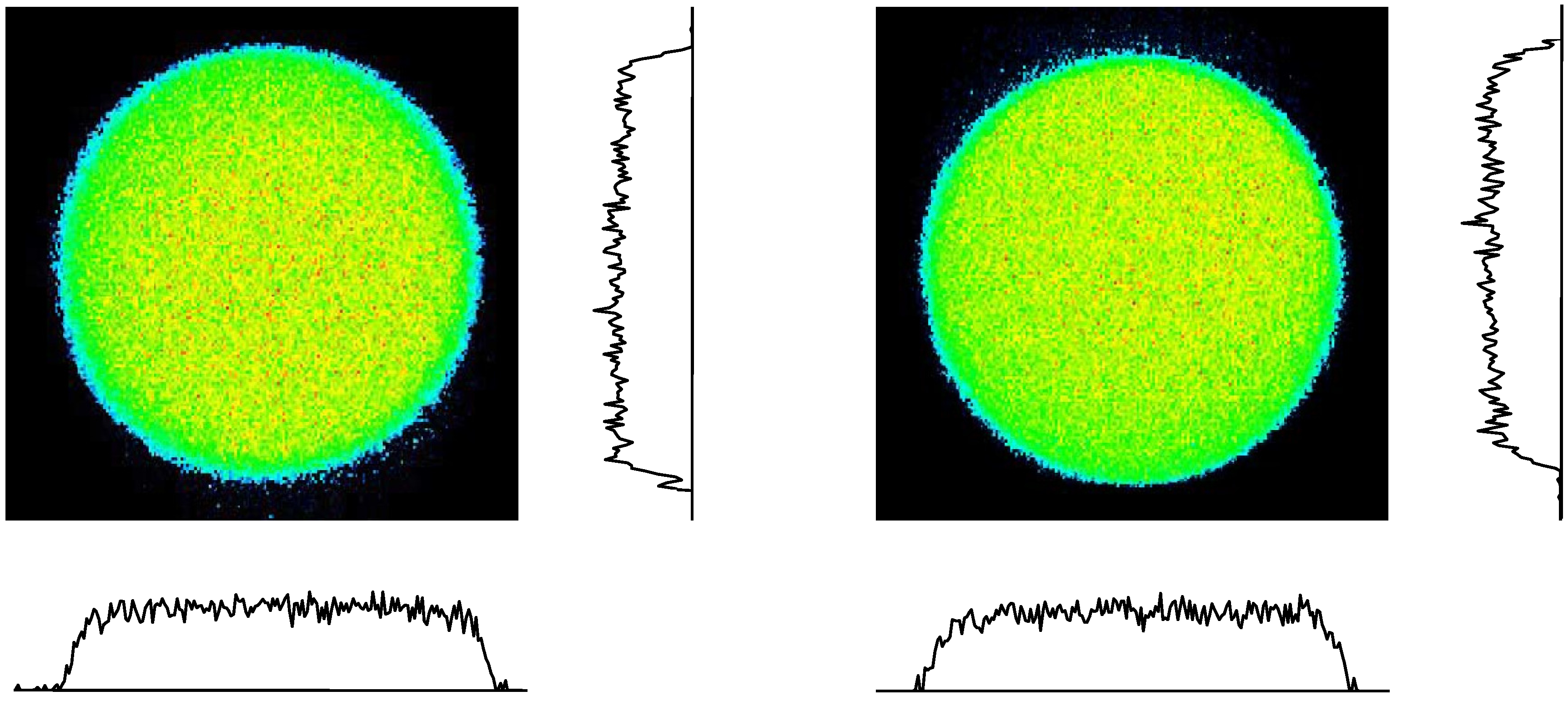
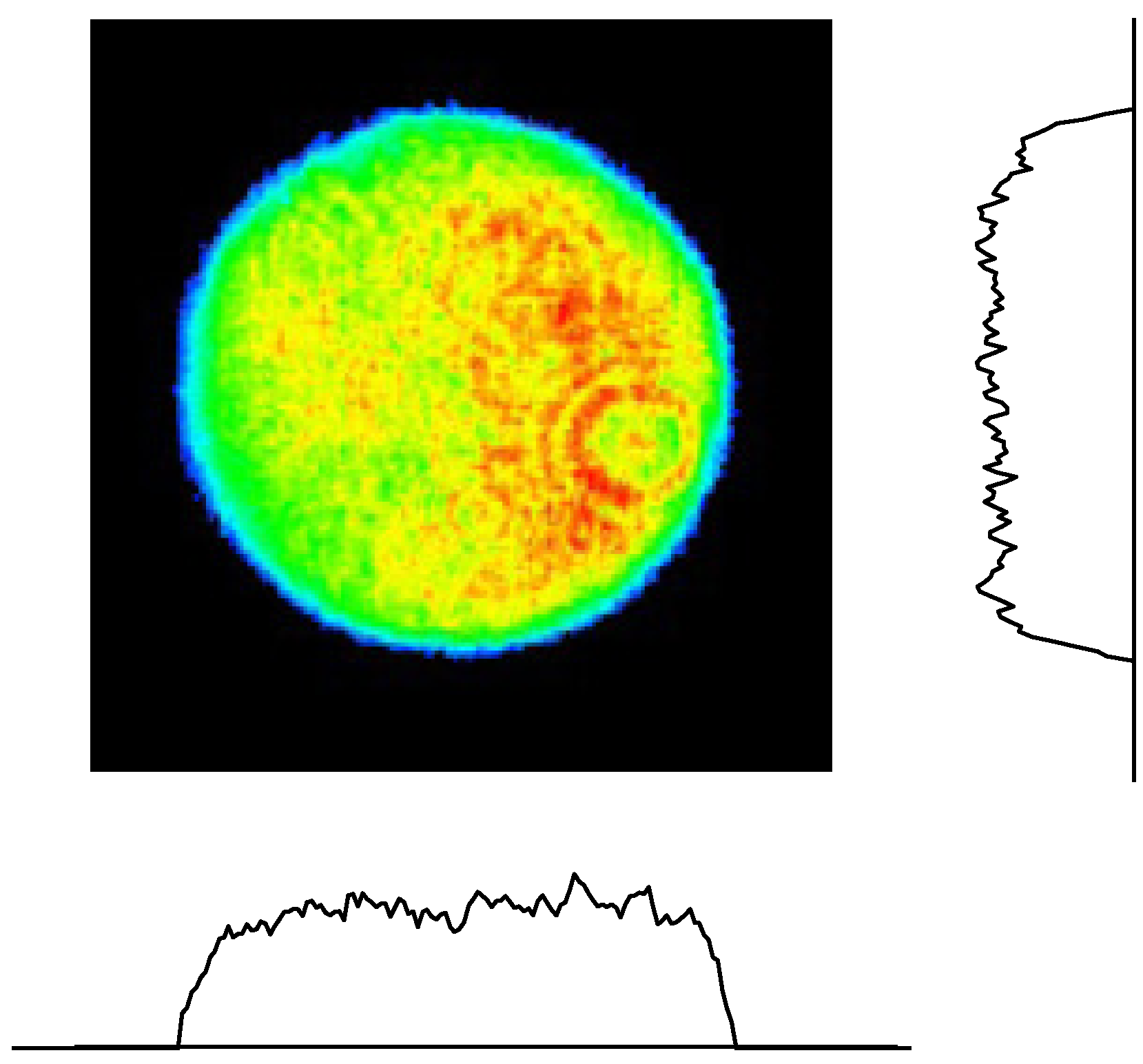
2.5. Spatiotemporal Quality

The near-field spatial intensity distributions of the green pump beams from each DKDP crystal and the intensity distributions along the vertical and horizontal cross sections of these beams are also shown in Figure 6. The near-field spatial intensity distributions are imaged by a CCD camera through a set of image-relay optics with high-energy (~100 J) green beams. As seen, the beams exhibit poor spatial qualities that are not suitable for directly pumping the Ti:sapphire amplifier. Most of the energy is concentrated in the outer edge area and, therefore, optical damage or parasitic oscillation could likely occur. Figure 7 shows the homogenized intensity distributions that are generated in the plane of the Ti:sapphire crystal for both pumping sides after passing through the DOEs. From these figures, it is seen that near-perfect flat-topped intensity distributions are successfully generated and the DOE capability for beam homogenization is demonstrated. Because the use of beam homogenizers can prevent crystal damage and parasitic oscillation due to the spatial irregularities of pump beams, this should allow greater amplification by allowing pumping at higher fluence. Figure 8 shows the near-field spatial profiles of 28 J amplified broadband beam from the final amplifier. The intensity distribution along the vertical and horizontal cross section of the beam is also shown. As seen, the beam profiles had near homogeneous flat-topped spatial intensity distributions. We have also evaluated the filling factor, which is defined as the ratio of peak intensity to average intensity of a spatial profile. A filling factor of 70% is obtained for 28 J broadband output beam. Amplified pulses are finally recompressed in a grating based compressor consisting of 1480 groove/mm gratings. The output pulse spectrum without pumping the final amplifier has a bandwidth of 50 nm (FWHM), and the recompressed pulse duration is 29.5 fs (FWHM) as shown in Figure 9. The pulse duration and spectral phase after the compressor are measured using high-dynamic range instruments, namely a single-shot commercial system (Wizzler, FASTLITE) or a home-build scanning transient grating FROG (frequency-resolved optical gating). The measured phase is used as feedback to the AOPDF to minimize the phase distortion.
Figure 6. Near-field spatial intensity distributions of the green beams from each DKDP crystal; (a) first crystal, (b) second crystal.
Applsci 03 00214 g006
Figure 7. Near-field spatial intensity distributions of the green beams from each crystal side.
Applsci 03 00214 g007
Figure 8. Near-field spatial intensity distribution of the final amplifier output.
Applsci 03 00214 g008
Figure 9. Recompressed pulse. Insert: spectrum.
Applsci 03 00214 g009
The contrast is measured using the third-order cross correlator (modified Sequoia unit by Amplitude Technologies, Chaland, France) in the several hundred picoseconds range without pumping final amplifier, as shown in Figure 10. The incident fluence for the cross correlator is 8 mJ/cm2. The peaks around the main pulse are attributed to multiple reflections of the main pulse at the optical components in the beam line and the third-order cross correlator. The post-pulses act as prepulses for the third-order cross-correlation signal. The contrast is improved by two orders of magnitude with the second saturable absorber in our system. At about 500 ps prior to the main pulse, the measured contrast is 1.4 × 10¹² (detection limited). It is very difficult to measure and evaluate the contrast while pumping the final amplifier due to the single-shot mode limitation. We have used the numerical model based on the Frantz–Nodvik simulation [69], and we have calculated the gains of the final amplifier for the main pulse and ASE. The calculation predicts that the contrast should be better than 5 × 10¹¹, even though we use the final amplifier in a maximum pumping condition. Considering the extinction ratio, over 200, of the ultrafast Pockels cell, the contrast is estimated to be over 1012 on the nanosecond time scale.
Figure 10. Contrast of the recompressed pulse.
Applsci 03 00214 g010

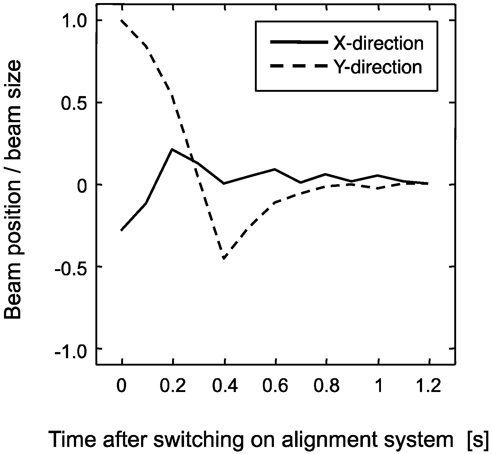
2.6. Improvements of Pointing Stability

We have installed and tested three automatic beam alignment systems at the front end of the laser system. The systems have been used for the pump lasers for the Ti:sapphire oscillator in the first CPA stage, for the OPCPA in the second CPA stage, and for the seed laser for the OPCPA after the first CPA stage. There are two main reasons for installation of the alignment system. The first is to bring the beams back to their set positions after switch-on of the laser system and, hence, to speed up the set-up procedure. The second is to compensate for thermal and mechanical drifts to keep the beam positions for minimizing the temporal variation in energy and pulse duration during laser operations. Beam positions of the seed laser for the OPCPA, for example, are monitored by two position-sensitive detectors (PSD) using leakage pulse energy through the back of two high-reflection mirrors (BeamLock, TEM Messtechnik GmbH, Hanover, Germany). The PSD is an analog device that operates with a 10–100 μs response time, so it is fast enough to monitor short-term fluctuations attributed to causes such as air turbulence and vibrations of the optical elements and benches. The software controlling the system calculates the centroid positions. If a deviation from the predetermined set-point values is detected, the beam is steered back by means of motorized actuators fitted to mirror mounts located upstream from the PSDs. Motorized mirrors are preferred to piezo driven mirrors because they hold their position when powered off. To avoid large fluctuations during stabilization due to the steep displacement, we introduce analog circuit to carefully adjust a proportional-integral-derivative controller. We also modify the circuit to hold the peak value of the pulsed signal from the PSD sensor because the sensor does not generate a signal during the shot-to-shot time period to detect pulses beams. Figure 11 shows the beam positions normalized by the beam size after switch-on during a typical day. As can be seen from this figure, beams are initially displaced by some amount, corresponding to up to one beam diameter. After about 1 s, displacements are corrected. The typical value of the pointing stability after the off-axis parabolic mirror (OAP) just before the target is 4–5 µrad. Actually, the stability of the whole system is perfect throughout the day. The result clearly demonstrates that the automatic alignment system has greatly improved the stability and consistency of the system’s performance. We plan to extend this stabilization system throughout the J-KAREN laser chain.
Figure 11. Vertical and horizontal deviations of beam positions normalized by the beam size after switch-on of the automatic beam alignment system.
Applsci 03 00214 g011

3. Applications with J-KAREN Laser System

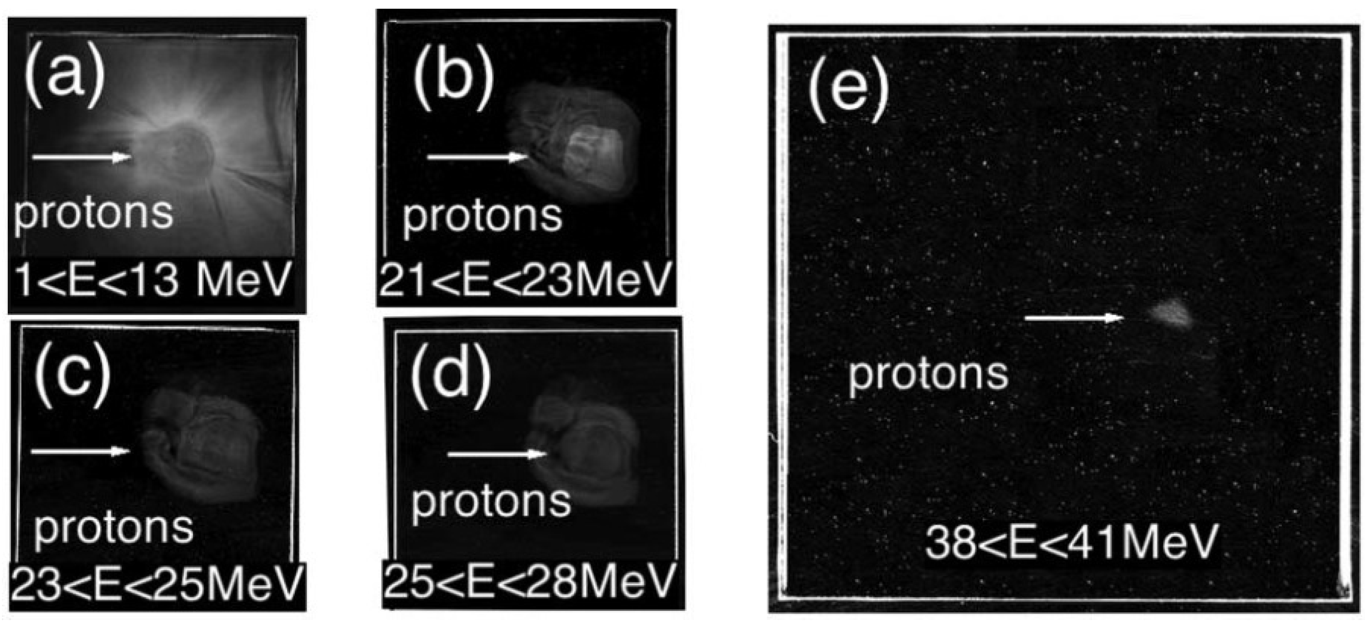
3.1. Laser-Accelerated Protons from Thin Foils

Since the first observation of the energetic ions from the interaction between the high-intensity laser pulses and thin-foil target at about three decades ago, many investigations have been carried out in this field. This is because the laser-driven energetic ions show many peculiar characteristics compared with those of the ion beams from conventional accelerators [70,71], thus many potential fields of applications are proposed, including medical application [72,73,74]. For the medical applications, there still exist many issues which we have to overcome. One of those is the extension of the maximum energy of the ions.
The maximum proton energy ever achieved in the last decade was ~60 MeV by using 400 J subpicosecond laser pulse from the laser system [75] which is basically single shot based operation, interacting with 100 μm foil. On the other hand, 24 MeV protons were demonstrated with the interaction between the 10 J, 100 fs laser pulses from the relatively compact laser system which can carry out repetitive operation, interacting with 3 μm target at the intensity of 1020 W/cm2 [76]. One of the important points for the application, especially for the medical application, the energetic ions should be accelerated repetitively with relatively small laser energy from a compact laser system. For obtaining higher energy of ions with relatively small laser energy, the increase of the intensity of the laser pulses on target is necessary.
The J-KAREN laser pulses are controlled temporally and spatially for achieving as high intensity as possible with the limited energy of laser pulses. The sub-ns contrast of the laser pulses is routinely obtained to 1010 without the plasma mirror system. The temporal profile of the main pulse and contrast in sub-ps time scale are optimized with the AOPDF using feedback from transient grating frequency-resolved optical gating (TG-FROG) apparatus. The pulse width and contrast, which are used in this experiment, are 36 fs (FWHM) and 1010, respectively. The derived on-target intensity is greater than 1021 W/cm2 with the focal spot size of 3 μm × 2 μm in FWHM [19]. The observed electron spectra show the slope temperature of more than 10 MeV. By assuming the ponderomotive scaling of the electron temperature [77], a normalized vector potential of the laser is a0 = 0.85 × 10⁻⁹ (I [W/cm2])1/2 λ [μm]) = 20, thus consistent with the estimated intensity of the laser pulse on target. The 7 J laser pulses are focused from the incidence angle of 45 degree onto the Stainless (SUS) Steel 2 μm tape target, which is also suitable for the repetitive operation. The proton detection is conducted with CR39 stacks which enable to detect the protons with energies up to 40 MeV. After the etching process with the 6 N KOH solution at 70 °C, clear etch pits caused by protons are revealed on the last layer of CR39, showing that the acceleration of protons is up to 40 MeV (as seen in Figure 12). The conversion efficiency of the laser energy into protons above 15 MeV is 0.1%. The estimate using the strong charge separation model [78] with the observed hot electron temperature of 10 MeV predicts the maximum proton energy of 54 MeV, which is in reasonable agreement with observed results.
Figure 12. Proton beam footprints on the CR39 plates for a 2 μm thick Stainless (SUS) target irradiated at the intensity of 1 × 10²¹ W/cm2. The proton energy range detected with each layer is also indicated.
Applsci 03 00214 g012
As a summary, the maximum proton energy of 40 MeV is obtained using only 7 J pulses from a Ti:sapphire laser system focused to very high intensity This proton energy enhancement and efficiency indicate the potential for simple thin metallic foils as sources for the laser-driven accelerator for medical application.

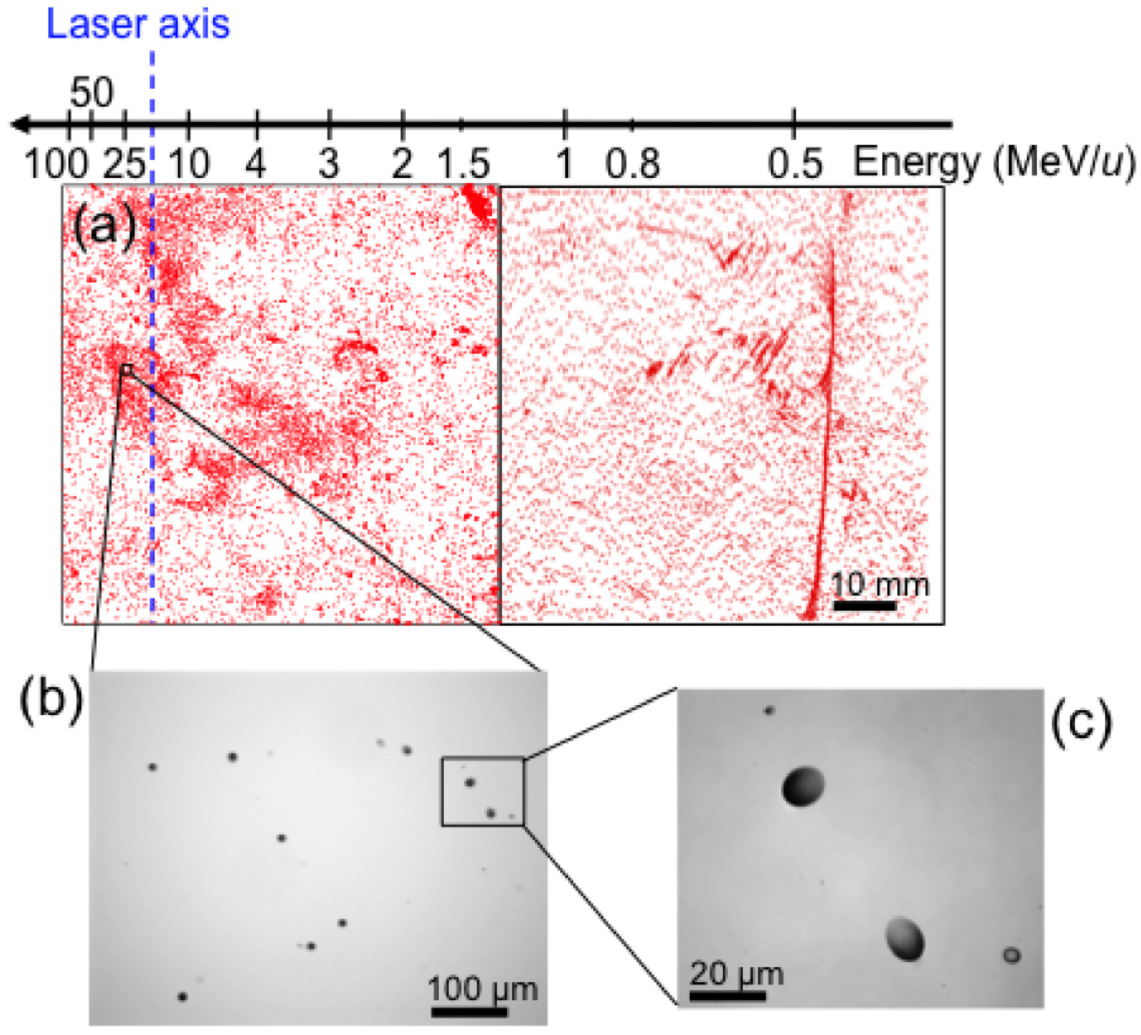
3.2. Laser-Accelerated Ions from Cluster-Gas Targets

In laser-driven ion accelerations, diagnosis of laser-accelerated ion beams attracts much attention and a precise characterization of accelerated ions is a crucial issue to develop a compact laser ion accelerator for medical and industrial applications. Solid state nuclear track detectors such as CR-39 detectors have been so far extensively used to detect laser-accelerated ions [18]. It is, however, impossible to detect ions with energies higher than the detection threshold limit of the CR-39, where the detection threshold limit is defined as the particle energy where the stopping power in the detector becomes smaller than the sensitivity of the detector. For example, in the case of BRYOTRAK (Fukuvi Chemical Industry, Fukui, Japan), it cannot detect He ions having energies of 10 MeV per nucleon and more.
Therefore, new methods to detect ions whose energies are far beyond the detection threshold limit of the CR-39 are required to further facilitate the laser ion acceleration experiments. We have demonstrated a new simple diagnosis method for high energy ions utilizing a single CR-39 detector mounted on plastic plates to identify the presence of the high energy component beyond the detection threshold limit of the CR-39 [79]. In addition, we have applied this method to the laser-driven ion acceleration experiments using cluster-gas targets [20].
The proof-of-principle experiments for the new ion detection method were carried out at TIARA facility in JAEA-TAKASAKI, which delivered 4He2+ ion beam with an energy of 100 MeV (25 MeV per nucleon). In contrast to the fact that the stopping power of the incident ion beam is too small to create etchable tracks in the 100-µm thick CR-39, a number of etch pits having elliptical openings were created on the rear surface of the CR-39. The growth curve analyses using the multi-step etching technique revealed the following scenario: The incident He ions once passed through the CR-39 without creating any etchable track, and various nuclear reactions such as nuclear spallation were induced by incident He ions in the plastic plates. As a result, the backscattered He and other heavy ions hit into the CR-39 from the rear surface and created the etchable tracks on the rear surface [79].
This method in combination with a magnetic energy spectrometer is applied to the laser-driven ion acceleration experiments using the cluster-gas target, which consists of submicron-size CO2 clusters and a background He gas, with J-KAREN laser system in JAEA. Figure 13a shows the whole view of etch pit distribution on the rear surface of CR-39. Experiments are conducted at a laser intensity of 7 × 10¹⁸ W/cm2 (40 fs, 1 J pulses) with a contrast ratio of 10−10. Etch pit radii indicate that ion species are He and other heavy ions. Detailed microscope investigations show that almost all of the etch pits on the rear surface have elliptical openings (as seen in Figure 13b,c) to demonstrates that laser-accelerated ions with energies up to 50 MeV per nucleon were generated [20].
Figure 13. (a) Whole view of etch pit distribution on the rear surface of the 70 × 140-mm wide CR-39; (b),(c) Typical images of etch pits on the rear surface.
Applsci 03 00214 g013

3.3. Laser-Accelerated Electrons from Gas Targets

Laser wake field acceleration (LWFA) [80], based on the effect of plasma waves excitation in the wake of an intense laser pulse, is now regarded as a basis for the next-generation of charged particle accelerators, competing with conventional accelerators in the energy gain per unit length. In order to generate a bunch with high quality, required for applications, the electrons should be duly injected into the wakefield and this injection should be controllable. Optical injection [81,82,83,84] has an advantage in using a regular pattern wakefield excited by a driver laser pulse. The most simple optical injection scheme is based on the utilization of two counter-propagating laser pulses [82]. In the case of the collision of two counter-propagating laser pulses, the first laser pulse (the driver pulse) generates the wakefield in a plasma, and the second laser pulse (the injecting pulse) colliding with the driver pulse provides the conditions for the electron trapping by the wake wave.
The experiments of the optical injection [17] have been performed with J-KAREN laser system [63]. The 40 fs driver laser pulse with 0.4 J energy is focused onto a 1-mm-diameter helium gas jet by an off-axis parabolic mirror (OAP). The peak irradiance is I0 = 3.0 × 10¹⁸ W/cm2. The 50 fs injecting pulse with 30 mJ energy is focused onto the focus point of the driver pulse by an OAP. Its peak irradiance, I1, is about 8.0 × 10¹⁶ W/cm2.
In order to demonstrate the optical injection, we must use plasma with a density below the self-injection threshold. When the plasma density, ne, is 1.0 × 1019 cm−3, the reproducibility drops to 0%. Figure 14 shows the result of the optical injection for ne = 1.0 × 1019 cm−3. The collision of the two laser pulses produces a monoenergetic electron bunch with the energy of about 134 MeV and a 3.5% root-mean-squar (RMS) energy spread. Using the sensitivity of the phosphor screen, calibrated with the help of a conventional electron accelerator, we estimate that the total charge of the monoenergetic electron bunch is 8.7 pC.
Figure 14. (a) A typical image of an energy distribution of the electron bunch at ne = 1.0 × 1019 cm−3, and a projection of the image onto the energy axis; (b) The monoenergetic electron bunch has a peak energy of 134 MeV and an energy spread of 3.5%.
Applsci 03 00214 g014

3.4. Xuv Electromagnetic Wave Generation via Flying Mirror

In this subsection, we review the flying mirror experiment, which produced extreme ultraviolet electromagnetic pulse. An intense, ultra-short laser pulse (driver) can generate a wake wave in an underdense plasma. When the intensity is high enough, the wake wave becomes nonlinear and its density profile forms a cusp shape. The phase velocity of the wake wave is approximately equal to the group velocity of the driver laser, i.e., vphc{1 − (ωpL)2}1/2, where c is the light speed in free space, ωp and ωL are the plasma and laser frequencies, respectively. Thus, the wake wave or density cusp works as a partially reflecting, moving mirror at a relativistic velocity; thus this is referred to relativistic flying mirror (RFM) [85]. When another laser pulse (source) directs to the RFM properly, it can be reflected. Because of the relativistic motion of the RFM, the frequency of the reflected pulse is upshifted to Applsci 03 00214 i003 and the pulse duration is compressed down to Applsci 03 00214 i004 due to the double Doppler effect, where γph = {1 − (vph/c)2}−1/2 is the Lorentz factor associated with the RFM, ωs and τs are the frequency and the pulse duration of the source pulse, respectively. After the proof-of-principle experiment [86], we conducted an improved experiment with head-on configuration using the J-KAREN laser system [87]. Here we describe the summary of the experiment.
In the experiment, the head-on configuration was adopted and this required the laser system modification due to possible returning pulses. The returning pulses are transmitted laser pulses through the target medium (He gas) and may cause damage in the laser optics. The estimated laser energies of the returning pulses are shown in Figure 15. The energies are estimated assuming the transmission through the target is 100% (the worst case). By installing Faraday isolators, Pockels cells, and a spatial filter we confirmed that even in the worst case there is no damage in the laser chain.
Figure 15. A schematic of head-on laser system. FI: Faraday isolator; PC: Pockels cell; SF: spatial filter; STR: pulse stretcher; COMP: pulse compressor; TRPT: laser transport. Typical energies in the laser chain and estimated energies of returning pulses are shown.
Applsci 03 00214 g015
In the flying mirror experiment with J-KAREN laser system, 420 mJ, 27 fs driver pulses and 42 mJ, 34 fs source pulses are focused onto the helium gas-jet target by off-axis parabolic mirrors. The estimated peak irradiances in vacuum for the driver and source pulses are 6.5 × 10¹⁸ W/cm2 and 1.2 × 10¹⁷ W/cm2, respectively. The maximum plasma density is (4.7 ± 1.3) × 1019 cm−3 at the absolute stagnation pressure of 2.1 MPa. By directing the source pulse, we have obtained the reflected laser spectrum in the extreme ultraviolet (XUV) region as shown in Figure 16 with a normal-incidence XUV spectrograph consisting of a spherical focusing mirror with broadband reflection, a transmission grating (5000 gr/mm), optical blocking filters, and a back-illuminated charge-coupled-device (CCD).
Figure 16. Spectrum of the radiation reflected by the relativistic flying mirror.
Applsci 03 00214 g016
The estimated photon number is (1.05 ± 0.03) × 109 photons in the spectral range from 12.8 to 22.0 nm assuming that the reflection is result of one flying mirror. The reflectivity of the mirror is approximately half of the theoretical expectation (as seen in Figure 16). The expected pulse duration is 520–920 as. In addition, the reflected pulse inherits properties of the initial source laser pulse such as polarization, coherence (space and time), a temporal structure. Thus, the XUV generation via the RFM can be a novel scheme to generate coherent, attosecond, X-ray pulses.

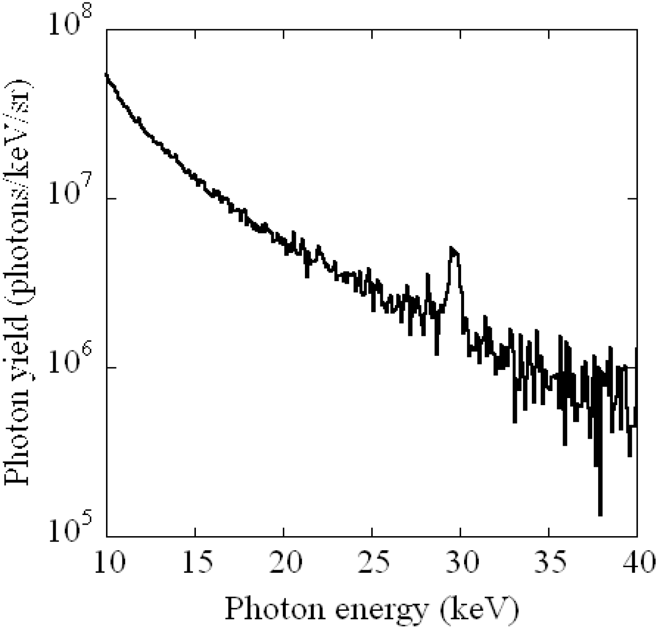
3.5. Hard X-ray Generation with Laser-Cluster Interaction

The laser-cluster interaction for the X-ray generation is attractive because of no debris production and a high X-ray conversion efficiency. Since the X-ray pulse duration, which is shorter than 1 picosecond, can be generated by the interaction [88], it may be applied for the real-time measurement of a phase transition in the crystal. In particular, Xenon (Xe) K-shell X-rays have a high energy close to 30 keV, which is suitable for the application.
However, there is a problem for the X-ray production. When the amplitude of laser pre-pulse is large, the clusters are broken by the prepulse before the main pulse arrival. Therefore, the high-contrast laser, J-KAREN laser system is utilized for the Xe K-shell X-ray generation. The laser is focused on the Xe clusters with 18 μm × 36 μm spot diameter (1/e2) at the peak intensity of 1019 W/cm2 [24]. The clusters are produced by adiabatic expansion of the Xe gas inside a specialized nozzle.
Figure 17 indicates the X-ray energy spectrum using Xe clusters measured with a hard X-ray charged coupled device. Besides the broad energy spectrum from 10 to 40 keV, there is a clear peak, the energy of which is around 30 keV. This peak corresponds to the Xe K-shell X-ray emission, which is due to the excited Xe K-shell electrons fall down to the ground state. The high peak laser intensity with the high contrast ratio enables the Xe K-shell X-ray emission efficiently.
Figure 17. Energy spectrum of the X-ray radiation generated by laser-cluster interaction.
Applsci 03 00214 g017
Although the laser-cluster interaction is studied vigorously, little is known about the underlying mechanism of Xe K-shell X-ray generation. This result gives us a hint for understanding the mechanism of the Xe X-ray generation.

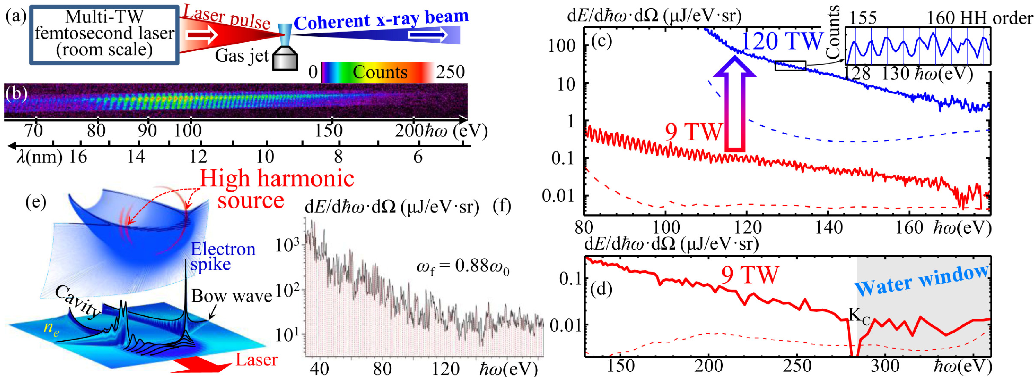
3.6. Soft X-ray Harmonic Comb Generation

Bright coherent X-ray sources are necessary for fundamental research and many applications in life sciences, material sciences, nanotechnology, etc. Using the J-KAREN laser system [63], we have discovered [89] a new regime of high-order harmonic generation by multi-TW relativistic-irradiance (I > 1018 W/cm2) [90] femtosecond lasers focused to gas jet targets, Figure 18a. Our further experiments [25] with the J-KAREN and Astra Gemini (CLF, RAL, Didcot, UK) [91] lasers show that comb-like spectra with hundreds of comparably intense even & odd harmonic orders, Figure 18b,c reaching the photon energy of 500 eV, including the “water window” spectral range, Figure 18d, are generated by either linearly or circularly polarized pulses. Importantly, the photon energy and number of photons are scalable with the laser power, Figure 18c.
Figure 18. High-order harmonics generation by multi-TW femtosecond lasers in gas jets [89,25]. (a) Experimental setup; (b) Typical single-shot raw data; (c) Harmonics spectra in absolute units and scalability with the laser power; (d) “Water window” radiation; (e) 3D PIC simulations demonstrating electron density spike and location of high harmonics source; (d) Harmonics spectrum from high-resolution 2D PIC simulation.
Applsci 03 00214 g018
Using particle-in-cell (PIC) simulations with the code REMP [92] and employing mathematical catastrophe theory [93,94], we introduce a new mechanism of harmonic generation by sharp, structurally stable, oscillating electron spikes, Figure 18e,f. The spikes appear at the joint of the wake wave and bow wave [95] boundaries. The structural stability of the cusp singularity ensures that the spike formation is robust and insensitive to perturbations.
Our results open the way to a compact bright coherent X-ray source which can be built using a university-lab-scale repetitive laser and accessible, replenishable, and debris-free gas jet target. Our discovery will benefit many areas of fundamental research and applications requiring a bright X-ray/XUV source for pumping, probing, imaging, and attosecond science.

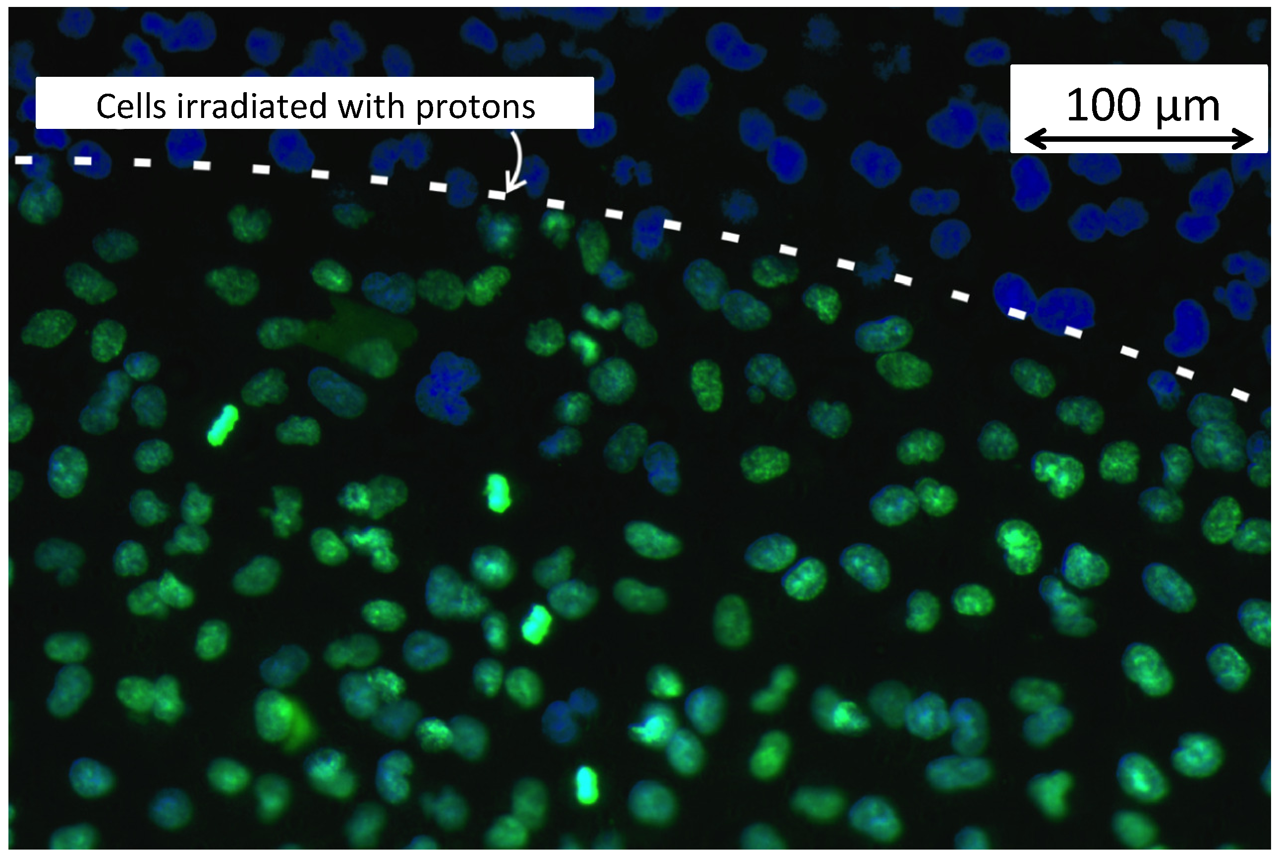
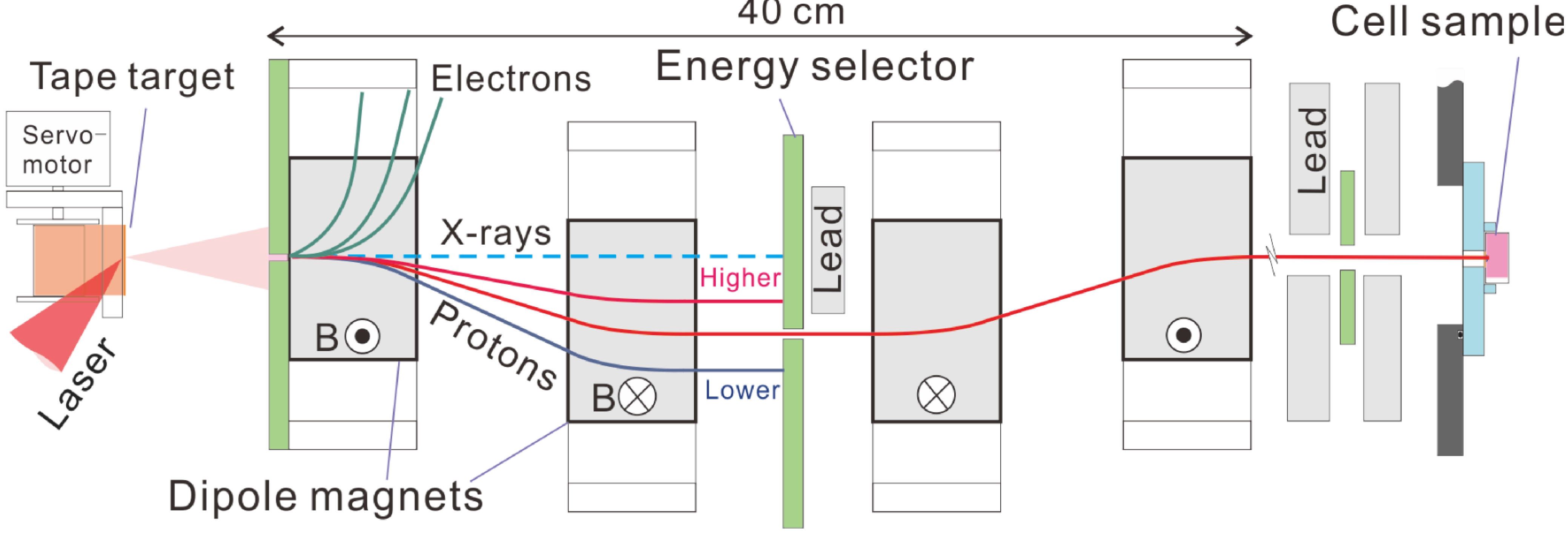
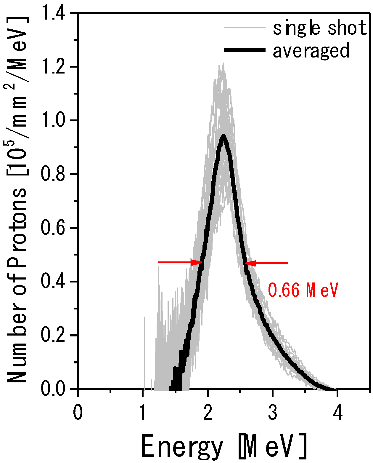
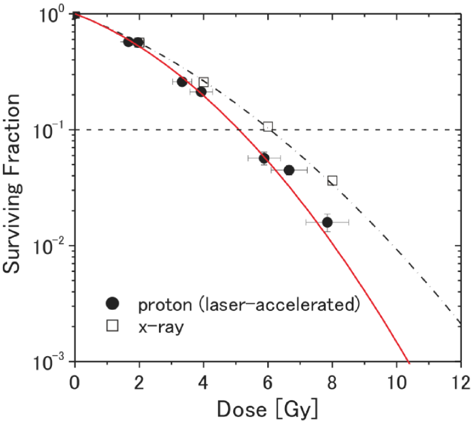
3.7. Radiation Biology with Laser-Accelerated Proton Beams

It has been widely recognized that the use of particle ion beams in cancer radiotherapy has the physical advantage of delivering longitudinally a more localized dose deposition associated with the well-known Bragg peak phenomenon [96]. However, the high capital cost of ion beam radiotherapy (IBRT) facilities remains a primary hurdle to a more widespread access to this treatment modality. Recently, high-intensity lasers have been suggested as a potential, cost-saving alternative [97] to conventional ion accelerators for the radiotherapy.
However, we must pose the fundamental question, “How does the biological effect of laser-accelerated ions compare to that of ions generated by conventional facilities?” We must address this basic question because some characteristics of a laser-driven ion beam significantly differ from those delivered by a more conventional accelerator. For example, one unique feature of a laser-driven proton source is the potential for extremely high current in a single ion bunch by virtue of both high bunch charge and short duration.
Figure 19. DNA double-strand breaks [98] induced by the irradiation of laser-accelerated protons with 20 Gy, indicated with the green signals.
Applsci 03 00214 g019
Figure 20. Experimental setup of the laser-driven quasi-monoenrgetic beam line [100].
Applsci 03 00214 g020
To address the fundamental question we have developed a laser-driven ion irradiation apparatus [98,99,100], which was the first attempt to investigate the radiobiological effects for laser-accelerated ions. For example, we have demonstrated DNA double-strand breaking of human cancer cells (as seen in Figure 19) by laser-driven proton bunches of short duration and high single bunch current. The latest configuration [100] of the beam line is seen in Figure 20. The J-KAREN laser system [11] at JAEA provided the intense laser pulses for target irradiation. Laser pulses of 1 J energy and 45 fs duration are focused to an intensity of ~5 × 10¹⁹ onto a polyimide target foil of 7.5-μm-thick. Compatible with the 1 Hz laser repetition-rate a new target area is provided for each pulse by advancing the foil tape with a servomotor. At the foil source the initial proton spectrum is continuous with a 4 MeV maximum kinetic energy.
The proton beam line consists of four dipole magnets. Each dipole magnet consists of a pair of rectangular permanent magnets, generating a central magnetic field of 0.78 T. The second and third magnetic fields are parallel with each other and oriented antiparallel to the first and fourth ones. Protons are collimated by an entrance pinhole and laterally displaced from the target normal axis in the midplane (midway between the second and third magnets) by the first two magnets. Proton energy and energy spread is set by a movable 5 mm diameter pinhole that is located in this midplane. The final two magnets steer protons back to the target normal axis. The transverse beam profile is adjusted by a pinhole. Protons are finally extracted from vacuum into air through a thin polyimide window of 7.5-μm-thickness and 10 mm diameter.
The proton energy spectrum transported through the beam line is measured with online single bunch Time-of-Flight (TOF) spectrometry [101]. The results are shown in Figure 21, where single-shot spectra obtained with 1-Hz repetition rate are individually shown in gray and the averaged spectrum is displayed in black. One can see that the intensity peak is stable at 2.25 MeV with the energy spread of 0.66 MeV (FWHM).
Figure 21. Energy spectra of protons monitored by the Time-of-Flight (TOF) spectrometer.
Applsci 03 00214 g021
Cultured cancer cells from the human salivary gland (HSG cells) were used for all cell experiments. HSG cells are purchased from Human Science Research Resource Bank (HSGc-C5, JCRB 1070). Using a colony formation assay, we have determined the value of relative biological effectiveness: RBE, which is one of the most important parameters in radiation biology. The cell survival ratio was measured 13 days after the cell irradiation by counting the number of cells that formed cell colonies. Figure 22 [100] shows the fraction of surviving cells after the irradiation with laser-accelerated protons (closed symbols) and a reference X-ray (open symbols) with a conventional clinical linac. RBE is evaluated from the dose at the 10% surviving fraction. Including errors on the proton dose, we determine the RBE value to be 1.20 ± 0.11 for the laser-accelerated protons. Using a conventional accelerator, Folkard et al. [102] obtained an RBE value of 1.4 ± 0.2 for hamster cells (V79) irradiated by 1.83-MeV protons. Although it is important to consider the difference between the cell lines, the two RBE values are nonetheless comparable. Therefore, we conclude that we observe no significant effect of the very high single bunch dose rate.
Figure 22. The fraction of surviving cells after the irradiation with the laser-accelerated protons (closed symbols) and a reference X-ray (open symbols) as a function of dose.
Applsci 03 00214 g022

3.8. Prospects of High Field Science Experiments

Nowadays with the fast growth of laser intensity it was realized that it can be used to probe an unexplored regime of interaction of charged particles with radiation and the properties of the vacuum [90,103,104]. The probabilities of the processes in high intensity electromagnetic (EM) fields involving electrons, positrons, and photons depend on three parameters (see details in [105]):
Applsci 03 00214 i001
where Applsci 03 00214 i005 and Applsci 03 00214 i006 are the charge and mass of an electron, c is the speed of light, Applsci 03 00214 i007 is Planck constant, ω and Applsci 03 00214 i008 are the EM field frequency and strength, respectively, Applsci 03 00214 i009 is the classical electron radius, Applsci 03 00214 i010 is the tensor of the EM field, and Applsci 03 00214 i011 and Applsci 03 00214 i012 are the electron, positron and photon momentum. The first parameter, a, is the dimensionless amplitude of the EM field, and is purely classical parameter. It has a meaning of electron energy gain over a distance of λ = c/ω in units of its rest energy, Applsci 03 00214 i013. When a is small the most probable are the processes with minimum possible number of photons. At a << 1 the probabilities become equal to the perturbation theory probabilities and plane waves represents an ensemble of individual photons. The linear regime of photon-electron (Thomson) scattering (see for example [106]) mentioned here is of a paramount importance for the generation of gamma-rays sourced for nuclear applications, both for accelerator based sources and also for laser based sources. When a ≈ 1 or a >> 1 the probabilities of absorbing different number of photons become comparable and the process becomes multiphoton, i.e., the probability has an essentially nonlinear dependence on the field. With the rapid development of laser technology EM pulses routinely obtain a >> 1. The EM pulse with the intensity corresponding to a above 30 has been generated by the J-KAREN laser system used in the experiments [19]. The second parameter εrad characterizes the radiation friction effects. At the laser field amplitude above Applsci 03 00214 i014, corresponding to 1023 W/cm2, the radiation friction makes the laser-matter interaction highly dissipative. This results in the high power gamma-ray flash generation [107]. The third parameter χe has a meaning of the ratio of EM field strength in the rest frame of the particle to the critical QED field equal to
Applsci 03 00214 i002
The field Applsci 03 00214 i015 produces a work over the Compton wavelength distance of Applsci 03 00214 i016 equal to mec2. Parameters χe and χγ are responsible for the magnitude of the quantum nonlinear effects: when a >> 1 these effects are maximized for χe,y ≈ 1. All these processes in high intensity EM fields are part of a new emerging branch of physics.
There are two principle experimental schemes aimed at the study of fundamental physics effects at high laser intensity [105,108]: (a) colliding laser pulses (all optical setup) and (b) laser-electron beam interaction. The first one could be employed for the study of direct vacuum breakdown, i.e., the electron-positron pair production under the action of intense EM field and the subsequent “avalanche”. The second scheme will allow for the study of basic processes: photon emission by an electron and a photon conversion into an electron-positron pair in intense EM field. Each of the experimental setups is characterized by its own set of extreme field limits, which mark the subsequent onset of the classical radiation reaction regime, the regime when quantum recoil becomes important, and the electron-positron pair production from vacuum.
When a high energy electron beam interacts with an extremely intense laser pulse the electrons undergo a cascade-type process, emitting multiple photons. As a result there is a massive production of electrons, positrons, and photons. The beginning of the cascade studies was marked by the E144 experiment at SLAC ( Applsci 03 00214 i017, χe = 0.3, and χγ =0.15) [108,109]. The modern day laser systems can produce Applsci 03 00214 i018, and GeV-level electron beams, which not only will boost the classical and quantum nonlinearities, but also significantly reduce the characteristic scale of the process, resulting in a cascade-type multistage process in the interaction of an electron beam with an intense laser pulse.
In Table 1 we summarize the parameters of the proposed experiment on the ultrarelativistic electron beam interaction with an intense PW-class laser pulse (see [107,109]). We note that the PW class laser (upgraded J-KAREN) has a potential for accelerating electrons up to 10 GeV energy. The interaction of a 10 GeV e-beam with an intense laser pulse is characterized by χe2.5 and χγ ≈1. Interaction of the laser light with the energetic electrons lowers the intensity threshold at which the radiation friction effects come into play. Such experimental conditions will make it possible the study of the high intensity particle physics effects in the near term.
Table 1. Peak values of the invariants χe and χγ for a 30 fs PW laser pulse (a = 100) interacting with electron beams of different energy (150 MeV, 1.25 GeV, and 10 GeV). arad is the normalized laser field at which the radiation friction effects come into play.
ParametersE (150 MeV) + PWLaserE (1.25 GeV) +PWLaserE (10 GeV) +PWlaser
γe30025002 × 104
χe0.050.52.5
χγ0.010.051
αrad = (εrad γe)−1/3603015

4. Compact, High Efficiency Laser System

4.1. Diode -Pumped Yb:YAG Chirped-Pulse Amplification Laser

As mentioned above, the invention of CPA together with the Ti:sapphire gain material has opened a route to experimental inquiries of laser-matter interactions in the relativistic regime. The Ti:sapphire CPA lasers in widespread use are pumped by lamp pumped green lasers, which are limited in the system size. However, one can overcome this limitation and also benefit from the improved stability and maintenance effort, which are required for many applications. Among several laser gain materials for short pulse amplification, the Yb:YAG is one of the most attractive materials for compact high intensity CPA lasers because of Yb3+ ion’s excellent spectroscopic and material properties for amplifying short pulses and for being pumped with commercially available near-infrared high power LD [110,111]. The LD pumped laser systems can be significantly more compact than similar lamp pumped laser systems. Features of the thin-disk geometry which are suitable for Yb:YAG laser material are very low thermal lens effects owing to efficient cooling with a good volume to surface ratio and the temperature gradient that is predominantly parallel to the beam direction, allowing for high spatial beam quality. Furthermore, it exhibits simple power scalability. Power can be increased by simply increasing the pump and seed diameters on the amplifier disk [110,111].
As noted above, ASE can generate unwanted preformed plasma and influence laser-plasma interactions driven by short pulses. OPCPA is becoming increasingly popular as a front end preamplifier system that can significantly reduce the ASE background level, improving the temporal contrast. OPCPA also provides broadband amplification [11], avoiding the strong gain narrowing in Yb:YAG. Thus, an OPCPA/Yb:YAG thin-disk CPA laser system is the most promising candidate for realizing a compact high-spatiotemporal-quality, high intensity laser system [11,112].
The laser system consists of an oscillator, an aberration-free stretcher, an OPCPA preamplifier, a multi-pass Yb:YAG ceramic thin disk amplifier, and a compressor. At a 40 MHz repetition-rate the oscillator delivered 20 nJ pulses of 5.5 nm bandwidth at a 1029 nm central wavelength. The near transform-limited pulse duration of 220 fs were stretched to about 1 ns with a pulse energy reduced to 12 nJ using an Öffner stretcher of 60% efficiency. Stretched pulses were subsequently amplified and then compressed by a grating pair. Following the stretcher and prior to amplification a commercial pulse selector extracted 10 Hz seed pulses that were synchronized to a Nd:YAG 532 nm pump laser. The gain of a three-stage (BBO) OPCPA preamplifier increased the output pulse energy to 3.5 mJ. Following preamplification the laser pulse energy was further increased by a Yb:YAG (7 at. %) ceramic thin disk amplifer. This thin disk is of 0.6 mm thickness and is mounted on a 1.0 mm thick YAG (undoped) disk of diameter of 14 mm. The Yb:YAG disk was pumped by the Q-CW fiber coupled LD unit at an energy of 2 J with 2 ms pump pulse duration (kW peak power). As shown in Figure 23, after 20 passes across the thin disk, we achieved the maximum output energy of 98.6 mJ with bandwidth of 2.2 nm (FWHM) and at 10 Hz.
Figure 23. Output energies from the Yb:YAG main amplifier versus the incident pump energy.
Applsci 03 00214 g023
The measured pulse duration using FROG (GRENOUILLE UPM-10-100, Swamp Optics) is 470 fs (FWHM), which is shorter than the pulse duration in the previous Yb:YAG CPA system using a regenerative amplifier [110]. The Yb:YAG amplifier output is subsequently recompressed with a gold grating pair. Because compressor efficiency exceeds 70% we anticipate the current compressed pulse energy to be near 60 mJ. Figure 24 illustrates the temporal (intensity) contrast of the final amplified pulse. The contrast level 150 ps before the main pulse is measured to be 10−8 using a third-order femtosecond cross-correlator.
Figure 24. Contrast of the recompressed pulse.
Applsci 03 00214 g024

4.2. Diode -Pumped Nd-Doped Mixed Scandium Garnets Ceramic Laser

One of the common high power pulsed lasers are based on a Nd-doped laser, but the pulses are not in the femtosecond region. Recently, the development of a new ceramic laser medium has been reported, namely the Nd-doped mixed scandium garnets Nd3+:(GSAG0.67:YSGG0.33). The Optical properties of Nd3+:(GSAG0.67:YSGG0.33) ceramic have already been reported by Okada et al. [113]. The Nd3+: (GSAG0.67:YSGG0.33) has a significantly broader spectral bandwidth (5 nm) and it is about four times broader than that of Nd:YAG ceramic. The stimulated emission cross section of the Nd3+: (GSAG0.67:YSGG0.33) at the peak wavelength is 7.8 × 10⁻²⁰ cm2 which is about two times higher than that of Nd-doped glasses. The thermal conductivity is 4.7 W/mK which is the four times higher thermal conductivity than Nd-doped glass materials. The ceramic which is fabricated based on vacuum sintering and nanotechnology method has a potential for a high peak, high average power laser system because they have a size scalability and stronger fracture toughness than single crystal.
We employed a simple Z-shaped cavity configuration. The laser oscillation experiment on this ceramic was performed in continuous wave operation. The ceramic was pumped with a 35 W fiber-coupled LD (100 μm core diameter, 0.12 NA) at the center wavelength around 808 nm. As the gain medium, a 3 mm thick Nd3+: (GSAG0.67:YSGG0.33) (CNd = 1 at. %) ceramic was used. It was mounted in a copper holder with water cooling and placed at the Brewster angle. It absorbed about 70% of the lunch pump power. The output couplers of 1%, 5% and 10% transmittances were used. The output powers as functions of the absorbed pump power are shown in Figure 25. With the 10%, 5% and 1% output couplers, the slope efficiency with respect to the absorbed pump power reached 26%, 24% and 10%, while the obtained optical-to-optical efficiency was 24%, 23% and 9%, respectively. With the 10% output coupling, the maximum output power of 1.74 W was obtained. The measured optical spectrum for the 10% output coupler and the fluorescence spectrum are shown in Figure 26. The optical spectrum consists of two peaks and these two peaks correspond to the peaks of fluorescence spectrum. In all cases, the measured laser profiles were multi-moded. We believe that further improving the fabrication method of the ceramic to reduce the scattering loss enable to increase the optical-to-optical efficiency. In the future, we aim for generation of mode-locked femtosecond pulses.
Figure 25. CW Output Power versus absorbed pump power for T = 1%, 5%, and 10%.
Applsci 03 00214 g025
Figure 26. CW laser spectrum for 10% output coupler and the fluorescence spectrum.
Applsci 03 00214 g026

5. Conclusions

The J-KAREN laser at KPSI of JAEA constitutes a highly productive, small-scale set-up with high repetition rate and excellent energy stability. The high intensity, high contrast optical pulses generated in our J-KAREN laser provide a superior source for studying relativistic laser-matter interactions. TheJ-KAREN laser has been used in a variety of pioneering experiments which have resulted in high-impact discoveries for high field science.
Detailed considerations presented here are applicable in general to the design and test of high power laser systems and applications. From advanced compact lasers to high power installations, our facilities span the wide range of laser capability. During the recent past KPSI, JAEA has delivered major new facilities to ensure that its research communities can continue to operate at the forefront of their field.

Acknowledgments

This work was partly performed by the “Consortium for Photon Science and Technology” program funded by the Special Coordination Funds for Promoting Science and Technology commissioned by MEXT of Japan, and partly the Special Coordination Fund (SCF) for Promoting Science and Technology commissioned by the MEXT of Japan. This work was also partially performed under the joint research project of the Institute of Laser Engineering, Osaka University. We also acknowledge the financial support from MEXT (Kakenhi 20244065, 21604008, 21740302, and 23740413), the JAEA President Grant, and the STFC facility access fund.

Conflict of Interest

The authors declare no conflict of interest.

References

  1. Strickland, D.; Mourou, G. Compression of amplified chirped optical pulses. Opt. Commun. 1985, 56, 219–221. [Google Scholar] [CrossRef]
  2. Umstadter, D. Review of physics and applications of relativistic plasmas driven by ultra-intense lasers. Phys. Plasmas 2001, 8, 1774–1785. [Google Scholar] [CrossRef]
  3. Ditmire, T.; Bless, S.; Dyer, G.; Edens, A.; Grigsby, W.; Hays, G.; Madison, K.; Maltsev, A.; Colvin, J.; Edwards, M.J.; et al. Overview of future directions in high energy-density and high-field science using ultra-intense lasers. Radia. Phys. Chem. 2004, 70, 535–552. [Google Scholar] [CrossRef]
  4. Aoyama, M.; Yamakawa, K.; Akahane, Y.; Ma, J.; Inoue, N.; Ueda, H.; Kiriyama, H. 0.85-PW, 33-fs Ti:sapphire laser. Opt. Lett. 2003, 28, 1594–1596. [Google Scholar]
  5. Liang, X.; Leng, Y.C.; Li, C.; Lin, L.; Zhao, B.; Jiang, Y.; Lu, X.; Hu, M.; Zhang, C.; Lu, H.; et al. Parasitic lasing suppression in high gain femtosecond petawatt Ti:sapphire amplifier. Opt. Exp. 2007, 15, 15335–15341. [Google Scholar] [CrossRef]
  6. Fourmaux, S.; Payeur, S.; Alexandrov, A.; Serbanescu, S.; Martin, F.; Ozaki, T.; Kudryashov, A.; Kieffer, J.C. Laser beam wavefront correction for ultra high intensities with the 200 TW laser system at the advanced laser light source. Opt. Exp. 2008, 16, 11987–11994. [Google Scholar] [CrossRef]
  7. Yanovsky, V.; Chvykov, V.; Kalinchenko, G.; Rousseau, P.; Planchon, T.; Matsuoka, T.; Maksimchuk, A.; Nees, J.; Cheriaux, G.; Mourou, G.; Krushelnick, K. Ultra-high intensity-300TW laser at 0.1 Hz repetition rate. Opt. Exp. 2008, 16, 2109–2114. [Google Scholar] [CrossRef]
  8. Sung, J.H.; Lee, S.K.; Yu, T.J.; Jeong, T.M.; Lee, J. 0.1 Hz 1.0 PW Ti:sapphire laser. Opt. Lett. 2010, 35, 3021–3023. [Google Scholar] [CrossRef]
  9. Wang, Z.; Liu, C.; Shen, Z.; Zhang, Q.; Teng, H.; Wei, Z. High-contrast 1.16 PW Ti:sapphire laser system combined with a doubled chirped-pulse amplification scheme and a femtosecond optical-parametric amplifier. Opt. Lett. 2011, 36, 3194–3196. [Google Scholar]
  10. Hooker, C.; Tang, Y.; Chekhlov, O.; Collier, J.; Divall, E.; Ertel, K.; Hawkes, S.; Parry, B.; Rajeev, P.R. Improving coherent contrast of petawatt laser pulses. Opt. Exp. 2011, 19, 2193–2203. [Google Scholar] [CrossRef]
  11. Kiriyama, H.; Mori, M.; Nakai, Y.; Shimomura, T.; Sasao, H.; Tanoue, M.; Kanazawa, S.; Wakai, D.; Sasao, F.; Okada, H.; et al. High temporal and spatial quality petawatt-class Ti:sapphire chirped-pulse amplification laser system. Opt. Lett. 2010, 35, 1497–1499. [Google Scholar] [CrossRef]
  12. Bahk, S.-W.; Rousseau, P.; Planchon, T.A.; Chvykov, V.; Kalintchenko, G.; Maksimchuk, A.; Mourou, G.A.; Yanovsky, V. Generation and characterization of the highest laser intensities (1022 W/cm2). Opt. Lett. 2004, 29, 2837–2839. [Google Scholar] [CrossRef]
  13. The Extreme Light Infrastructure. Available online: http://www.extreme-light-infrastructure.eu/ (accessed on 7 December 2012).
  14. Ceccotti, T.; Lévy, A.; Popescu, H.; Réau, F.; D’Oliveira, P.; Monot, P.; Geindre, J.P.; Lefebvre, E.; Martin, P. Proton acceleration with high-intensity ultrahigh-contrast laser pulses. Phys. Rev. Lett. 2007, 99, 185002. [Google Scholar] [CrossRef]
  15. Antici, P.; Fuchs, J.; d’Humières, E.; Lefebvre, E.; Borghesi, M.; Brambrink, E.; Cecchetti, C.A.; Gaillard, S.; Romagnani, L.; Sentoku, Y.; et al. Energetic protons generated by ultrahigh contrast laser pulses interacting with ultrathin targets. Phys. Plasmas 2007, 14, 030701. [Google Scholar] [CrossRef]
  16. Esarey, E.; Schroeder, C.B.; Leemans, W.P. Physics of laser-driven plasma-based electron accelerator. Rev. Mod. Phys. 2009, 81, 1229–1286. [Google Scholar] [CrossRef]
  17. Kotaki, H.; Daito, I.; Kando, M.; Hayashi, Y.; Kawase, K.; Kameshima, K.; Fukuda, Y.; Homma, T.; Ma, J.; Chen, L.-M.; et al. Electron optical injection with head-on and counter-crossing colliding laser pulses. Phys. Rev. Lett. 2009, 103, 194803. [Google Scholar] [CrossRef]
  18. Fukuda, Y.; Faenov, A.Y.; Tampo, M.; Pikuz, T.A.; Nakamura, T.; Kando, M.; Hayashi, Y.; Yogo, A.; Sakaki, H.; Kameshima, T.; et al. Energy increase in multi-MeV ion acceleration in the interaction of a short pulse laser with a cluster-gas target. Phys. Rev. Lett. 2009, 103, 165002. [Google Scholar] [CrossRef]
  19. Ogura, K.; Nishiuchi, M.; Pirozhkov, A.S.; Tanimoto, T.; Sagisaka, A.; Esirkepov, T.Z.; Kando, M.; Shizuma, T.; Hayakawa, T.; Kiriyama, H.; et al. Proton acceleration to 40 MeV using a high intensity, high contrast OPCPA/Ti:Sapphire hybrid laser system. Opt. Lett. 2012, 37, 2868–2870. [Google Scholar] [CrossRef]
  20. Fukuda, Y.; Sakaki, H.; Kanasaki, M.; Yogo, A.; Jinno, S.; Tampo, M.; Faenov, A.Y.; Pikuz, T.A.; Hayashi, Y.; Kando, M.; et al. Identification of high energy ions using backscattered particles in laser-driven ion acceleration with cluster-gas targets. Radiat. Meas. 2012, in press. [Google Scholar]
  21. Rousse, A.; Phuoc, K.T.; Shah, R.; Pukhov, A.; Lefebvre, E.; Malka, V.; Kiselev, S.; Burgy, F.; Rousseau, J.-P.; Umstadter, D.; et al. Production of a keV X-ray bean from synchrotron radiation in relativistic laser-plasma interaction. Phys. Rev. Lett. 2004, 93, 135005. [Google Scholar] [CrossRef]
  22. Kando, M.; Fukuda, Y.; Pirozhkov, A.S.; Ma, J.; Daito, I.; Chen, L.-M.; Esirkepov, T.Z.; Ogura, K.; Homma, T.; Hayashi, Y.; et al. Demonstration of laser-frequency upshift by electron-density modulations in a plasma wakefield. Phys. Rev. Lett. 2007, 99, 135001. [Google Scholar] [CrossRef]
  23. Fukuda, Y.; Faenov, A.Y.; Pikuz, T.; Kando, M.; Kotaki, H.; Daito, I.; Ma, J.; Chen, L.M.; Homma, T.; Kawase, K.; et al. Soft X-ray source for nanostructure imaging using femtosecond-laser-irradiated clusters. Appl. Phys. Lett. 2008, 92, 121110. [Google Scholar] [CrossRef]
  24. Hayashi, Y.; Pirozhkov, A.S.; Kando, M.; Fukuda, Y.; Faenov, A.; Kawase, K.; Pikuz, T.; Nakamura, T.; Kiriyama, H.; Okada, H.; et al. Efficient generation of Xe K-shell X rays by high-contrast interaction with submicrometer clusters. Opt. Lett. 2011, 36, 1614–1616. [Google Scholar] [CrossRef]
  25. Pirozhkov, A.S.; Kando, M.; Esirkepov, T.Z.; Gallegos, P.; Ahmed, H.; Ragozin, E.N.; Faenov, A.Y.; Pikuz, T.A.; Kawachi, T.; Sagisaka, A.; et al. Soft X-ray harmonic comb from relativistic electron spikes. Phys. Rev. Lett. 2012, 108, 135004. [Google Scholar] [CrossRef]
  26. Zhang, Z.; Nishimura, H.; Namimoto, T.; Fujioka, S.; Arikawa, Y.; Nishikino, M.; Kawachi, T.; Sagisaka, A.; Hosoda, H.; Orimo, S.; et al. Quantitative measurement of hard X-ray spectra for high intensity laser produced plasma. Rev. Sci. Instrum. 2012, 85, 53502. [Google Scholar]
  27. Faenov, A.F.; Skobelev, I.Y.; Pikuz, T.A.; Pikuz, S.A.; Fortov, V.E.; Fukuda, Y.; Hayashi, Y.; Pirozhkov, A.; Kotaki, H.; Shimomura, T.; et al. X-ray spectroscopy diagnoses of clusters surviving under prepulses of ultraintense femtosecond laser pulse irradiation. Laser Part. Beams. 2012, 30, 481–488. [Google Scholar] [CrossRef]
  28. Ogura, K.; Shizuma, T.; Hayakawa, T.; Yogo, A.; Nishiuchi, M.; Orimo, S.; Sagisaka, A.; Pirozhkov, A.; Mori, M.; Kiriyama, H.; et al. Proton-induced nuclear reactions using compact high-contrast high-intensity laser. Appl. Phys. Exp. 2009, 2, 066001. [Google Scholar] [CrossRef]
  29. Ogura, K.; Shizuma, T.; Hayakawa, T.; Yogo, A.; Nishiuchi, M.; Orimo, S.; Sagisaka, A.; Pirozhkov, A.; Mori, M.; Kiriyama, H.; et al. Complementary characterization of radioactivity produced by repetitive laser-driven proton beam using shot-to-shot proton spectral measurement and direct activation measurement. Jpn. J. Appl. Phys. 2012, 51, 048003. [Google Scholar] [CrossRef]
  30. Dromey, B.; Zepf, M.; Gopal, A.; Lancaster, K.; Wei, M.S.; Krusheknick, K.; Tatarakis, M.; Vakakis, N.; Moustaizis, S.; Kodama, R.; et al. High harmonic generation in the relativistic limit. Nat. Phys. 2006, 2, 456–459. [Google Scholar] [CrossRef]
  31. Neely, D.; Foster, P.; Robinson, A.; Lindau, F.; Lundh, O.; Persson, A.; Wahlström, C.G.; McKenna, P. Enhanced proton beams from ultrathin targets driven by high contrast laser pulse. Appl. Phys. Lett. 2006, 89, 021502. [Google Scholar] [CrossRef]
  32. Minkovski, N.; Petrov, G.I.; Saltiel, S.M.; Albert, O.; Etchepare, J. Nonlinear polarization rotation and orthogonal polarization generation experienced in a single-beam configuration. J. Opt. Soc. Am. B 2004, 21, 1659–1664. [Google Scholar]
  33. Jullien, A.; Albert, O.; Burgy, F.; Hamoniaux, G.; Rousseau, J.P.; Chambaret, J.P.; Augé-Rochereau, F.; Chériaux, G.; Etchepare, J.; Minkovski, N.; et al. 10−10 temporal contrast for femtosecond ultraintense lasers by crosspolarized wave generation. Opt. Lett. 2005, 30, 920–922. [Google Scholar] [CrossRef]
  34. Itatani, J.; Faure, J.; Nantel, M.; Mourou, G.; Watanabe, S. Suppression of the amplifiedspontaneous emissionin chirpedpulse-amplification lasers by clean high-energy seed-pulse injection. Opt. Commun. 1998, 148, 70–74. [Google Scholar] [CrossRef]
  35. Kiriyama, H.; Mori, M.; Nakai, Y.; Shimomura, T.; Tanoue, M.; Akutsu, A.; Okada, H.; Motomura, T.; Kondo, S.; Kanazawa, S.; et al. Generation of high-contrast and high-intensity laser pulses using an OPCPA preamplifier in a double CPA, Ti:sapphire laser system. Opt. Commun. 2009, 282, 625–628. [Google Scholar] [CrossRef]
  36. Dromey, B.; Kar, S.; Zepf, M.; Foster, P. The plasma mirror—A subpicosecond optical switch for ultrahigh power lasers. Rev. Sci. Instrum. 2004, 75, 645–649. [Google Scholar] [CrossRef]
  37. Taur, C.; Quéré, F.; Geindre, J.-P.; Levy, A.; Ceccotti, T.; Monot, P.; Bougeard, M.; Réau, F.; D’oliveira, P.; Audebert, P.; et al. Plasma mirrors for ultrahighintensity optics. Nat. Phys. 2007, 3, 424–429. [Google Scholar] [CrossRef]
  38. Liu, J.; Okamura, K.; Kida, Y.; Kobayashi, T. Temporal contrast enhancement of femtosecond pulses by a self-diffraction process in a bulk Kerr medium. Opt. Exp. 2010, 18, 22245–22254. [Google Scholar] [CrossRef]
  39. Chvykov, V.; Rousseau, P.; Reed, S.; Kalinchenko, G.; Yanovsky, V. Generation of 1011 contrast 50 TW laser pulses. Opt. Lett. 2006, 31, 1456–1458. [Google Scholar] [CrossRef]
  40. Wittmann, T.; Geindre, J.P.; Audebert, P.; Marjoribanks, R.S.; Rousseau, J.P.; Burgy, F.; Douillet, D.; Lefrou, T.; Phuoc, K.T.; Chambaret, J.P. Towards ultrahigh-contrast ultraintense laser pulses—Complete characterization of a double plasma-mirror pulse cleaner. Rev. Sci. Instrum. 2006, 77, 083109. [Google Scholar] [CrossRef]
  41. Kim, I.J.; Choi, I.W.; Lee, S.K.; Janulewicz, K.A.; Sung, J.H.; Yu, T.J.; Kim, H.T.; Yun, H.; Jeong, T.M.; Lee, J. Spatio-Temporal characterization of double plasma mirror for ultrahigh contrast and stable laser pulse. Appl. Phys. B 2011, 104, 81–86. [Google Scholar] [CrossRef]
  42. Dubietis, A.; Jonusauskas, G.; Piskarskas, A. Powerful femtosecond pulse generation by chirped and stretched pulse parametric amplification in BBO crystal. Opt. Commun. 1992, 88, 437–440. [Google Scholar] [CrossRef]
  43. Ross, I.N.; Matousek, P.; Towrie, M.; Langley, A.J.; Collier, J.L. The prospects for ultrashort pulse duration and ultrahigh intensity using optical parametric chirped pulse amplifiers. Opt. Commun. 1997, 144, 125–133. [Google Scholar] [CrossRef]
  44. Kitagawa, Y.; Fujita, H.; Kodama, R.; Yoshida, H.; Matsuo, S.; Jitsuno, T.; Kawasaki, T.; Kitamura, H.; Kanabe, T.; Sakabe, S.; et al. Prepulse-free petawatt laser for a fast ignitor. IEEE J. Quantum Electron. 2004, 40, 281–293. [Google Scholar] [CrossRef]
  45. Musgrave, I.O.; Hernandez-Gomez, C.; Canny, D.; Collier, J.; Heathcote, R. Minimization of the impact of a broad bandwidth high-gain nonlinear preamplifier to the amplified spontaneous emission pedestal of the Vulcan petawatt laser facility. Appl. Opt. 2007, 46, 6978–6983. [Google Scholar] [CrossRef]
  46. Blanchot, N.; Behar, G.; Berthier, T.; Bignon, E.; Boubault, F.; Chappuis, C.; Coïc, H.; Damiens-Dupont, C.; Ebrardt, J.; Gautheron, Y.; et al. Overview of PETAL, multi-petawatt project on the LIL facility. Plasma Phys. Controlled Fusion 2008, 50, 124045. [Google Scholar] [CrossRef]
  47. Schwarz, J.; Rambo, P.; Geissel, M.; Kimmel, M.; Brambrink, E.; Atherton, B.; Glassman, J. A hybrid OPCPA/Nd:phosphate glass multi-terawatt laser system for seeding of a petawatt laser. Opt. Commun. 2008, 281, 4984–4992. [Google Scholar] [CrossRef]
  48. Ple, F.; Pittman, M.; Jamelot, G.; Chambaret, J.P. Design and demonstration of a high-energy booster amplifier for a high-repetition rate petawatt class laser system. Opt. Lett. 2007, 32, 238–240. [Google Scholar] [CrossRef]
  49. Ertel, K.; Hooker, C.; Hawkes, S.J.; Parry, B.T.; Collier, J.L. ASE suppression in a high energy titanium sapphire amplifier. Opt. Exp. 2008, 16, 8039–8049. [Google Scholar]
  50. Fourmaux, S.; Payeur, S.; Buffechoux, S.; Lassonde, P.; St Pierre, C.; Martin, F.; Kieffer, J.C. Pedestal cleaning for high laser pulse contrast ratio with a 100 TW class laser system. Opt. Exp. 2011, 19, 8486–8497. [Google Scholar]
  51. Hong, K.H.; Hou, B.; Nees, J.A.; Power, E.; Mourou, G.A. Generation and measurement of >108 intensity contrast ratio in a relativistic kHz chirped-pulse amplified laser. Appl. Phys. B 2005, 81, 447–457. [Google Scholar] [CrossRef]
  52. Cheriaux, G.; Rousseau, P.; Salin, F.; Chambaret, J.P.; Walker, B.; Dimauro, L.F. Aberration-free stretcher design for ultrashort-pulse amplification. Opt. Lett. 1996, 21, 414–416. [Google Scholar] [CrossRef]
  53. Tavella, F.; Marcinkevicius, A.; Krausz, F. Investigation of the superfluorescence and signal amplification in an ultrabroadband multiterawatt optical parametric chirped pulse amplifier system. New J. Phys. 2006, 8, 219. [Google Scholar] [CrossRef]
  54. Okada, H.; Kiriyama, H.; Mori, M.; Nakai, Y.; Shimomura, T.; Tanoue, M.; Kondo, S.; Kanazawa, S.; Daido, H.; Kimura, T.; et al. Demonstration of highly efficient broadband amplification in an optical parametric chirped-pulse amplifier system. Opt. Rev. 2009, 16, 1–3. [Google Scholar] [CrossRef]
  55. Shah, R.C.; Johnson, R.P.; Shimada, T.; Flippo, K.A.; Fernandez, J.C.; Hegelich, B.M. High-Temporal contrast using low-gain optical parametric amplification. Opt. Lett. 2009, 34, 2273–2275. [Google Scholar]
  56. Kiriyama, H.; Mori, M.; Nakai, Y.; Yamamoto, Y.; Tanoue, M.; Akutsu, A.; Shimomura, T.; Kondo, S.; Kanazawa, S.; Daido, H.; et al. High-energy, high-contrast, multiterawatt laser pulses by optical parametric chirped-pulse amplification. Opt. Lett. 2007, 32, 2315–2317. [Google Scholar] [CrossRef]
  57. Bagnoud, V.; Begishev, I.A.; Guardalben, M.J.; Puth, J.; Zuegel, J.D. 5 Hz, >250 mJ optical parametric chirped-pulse amplifier at 1053 nm. Opt. Lett. 2005, 30, 1843–1845. [Google Scholar]
  58. Wnuk, P.; Stepanenko, Y.; Radzewicz, C. Multi-terawatt chirped pulse optical parametric amplifier with a time-shear power amplification stage. Opt. Exp. 2009, 17, 15264–15273. [Google Scholar]
  59. Chekhlov, O.V.; Collier, J.L.; Ross, I.N.; Bates, P.K.; Notley, M.; Hernandez-Gomez, C.; Shaikh, W.; Danson, C.N.; Neely, D.; Matousek, P.; et al. 35 J broadband femtosecond optical parametric chirped pulse amplification system. Opt.Lett. 2006, 31, 3665–3667. [Google Scholar] [CrossRef]
  60. Suzuki, M.; Kiriyama, H.; Daito, I.; Okada, H.; Nakai, Y.; Orimo, S.; Sato, M.; Tamaoki, Y.; Yoshii, T.; Maeda, J.; et al. Multimillijoule, nonlinear preamplifier for high intensity femtosecond Yb:YAG chirped-pulse amplification lasers at 1030 nm. Appl. Phys. B 2009, 97, 379–382. [Google Scholar] [CrossRef]
  61. Kiriyama, H.; Inoue, N.; Akahane, Y.; Yamakawa, K. Prepulse-Free, multi-terawatt, sub-30 fs laser system. Opt. Exp. 2006, 14, 438–445. [Google Scholar] [CrossRef]
  62. Pittman, M.; Ferré, S.; Rousseau, J.P.; Notebaert, L.; Chambaret, J.P.; Chériaux, G. Design and characterization of a near-diffraction-limited femtosecond 100 TW 10 Hz high-intensity laser system. Appl. Phys. B 2002, 74, 529–535. [Google Scholar] [CrossRef]
  63. Kiriyama, H.; Mori, M.; Nakai, Y.; Shimomura, T.; Tanoue, M.; Akutsu, A.; Kondo, S.; Kanazawa, S.; Okada, H.; Motomura, T.; et al. High-Contrast, highintensity laser pulse generation using a nonlinear preamplifier in a Ti:sapphire laser system. Opt. Lett. 2008, 33, 645–647. [Google Scholar] [CrossRef]
  64. Planchon, T.A.; Amir, W.; Childress, C.; Squier, J.A.; Durfee, C.G. Measurement of pump-induced transient lensing in a cryogenically-cooled high average power Ti:sapphire amplifier. Opt. Exp. 2008, 16, 18557–18564. [Google Scholar]
  65. Eimerl, D. Quadrature frequency conversion. IEEE J. Quantum Electron. 1987, 23, 1361–1371. [Google Scholar] [CrossRef]
  66. Kiriyama, H.; Nakano, F.; Yamakawa, K. High-efficiency frequency doubling of a Nd:YAG laser in a two-pass quadrature frequency-conversion scheme using CsLiB6O10 crystals. J. Opt. Soc. Am. B 2002, 19, 1857–1864. [Google Scholar] [CrossRef]
  67. Tanaka, M.; Kiriyama, H.; Ochi, Y.; Nakai, Y.; Sasao, H.; Okada, H.; Daido, H.; Bolton, P.; Kawanishi, S. High-energy, spatially flat-top green pump laser by beam homogenization for petawatt scale Ti:sapphire laser systems. Opt. Commun. 2009, 282, 4401–4403. [Google Scholar] [CrossRef]
  68. Kiriyama, H.; Tanaka, M.; Ochi, Y.; Nakai, Y.; Sasao, H.; Okada, H.; Mori, M.; Shimomura, T.; Kanazawa, S.; Daido, H.; et al. 100 J level green laser beam homogenization to pump a petawatt class Ti:sapphire chirped-pulse amplification laser system. Rev. Laser Eng. 2009, 37, 467–469. [Google Scholar]
  69. Frantz, L.M.; Nodvik, J.S. Theory of pulse propagation in a laser amplifier. J. Appl. Phys. 1963, 34, 2346–2349. [Google Scholar] [CrossRef]
  70. Borghesi, M.; Fuchs, J.; Bulanov, S.V.; MacKinnon, A.J.; Patel, P.K.; Roth, M. Fast ion generation by high-intensity laser irradiation of solid targets and applications. Fus. Sci. Technol. 2006, 49, 412–439. [Google Scholar]
  71. Daido, H.; Nishiuchi, M.; Pirozhkov, A.S. Review of laser-driven ion sources and their applications. Rep. Prog. Phys. 2012, 75, 056401. [Google Scholar] [CrossRef]
  72. Bulanov, S.V.; Khoroshkov, V.S. Feasibility of using laser ion accelerators in proton therapy. Plasma Phys. Rep. 2002, 28, 453–456. [Google Scholar] [CrossRef]
  73. Fourkal, E.; Shahine, B.; Ding, M.; Li, J.S.; Tajima, T.; Ma, C.M. Particle in cell simulation of laser-accelerated proton beams for radiation therapy. Med. Phys. 2002, 29, 2788–2798. [Google Scholar] [CrossRef]
  74. Malka, V.; Fritzler, S.; Lefebvre, E.; d'Humières, E.; Ferrand, R.; Grillon, G.; Albaret, C.; Meyroneinc, S.; Chambaret, J.P.; Antonetti, A.; et al. Practicability of protontherapy using compact laser systems. Med. Phys. 2004, 31, 1587–1592. [Google Scholar] [CrossRef]
  75. Hatchett, S.P.; Brown, C.G.; Cowan, T.E.; Henry, E.A.; Johnson, J.S.; Key, M.H.; Koch, J.A.; Langdon, A.B.; Lasinski, B.F.; Lee, R.W.; et al. Electron, photon, and ion beams from the relativistic interaction of Petawatt laser pulses with solid targets. Phys. Plasmas 2000, 7, 2076–2082. [Google Scholar] [CrossRef]
  76. Mackinnon, A.J.; Sentoku, Y.; Patel, P.K.; Price, D.W.; Hatchett, S.; Key, M.H.; Andersen, C.; Snavely, R.; Freeman, R.R. Enhancement of proton acceleration by hot-electron recirculation in thin foils irradiated by ultraintense laser pulses. Phys. Rev. Lett. 2002, 88, 215006. [Google Scholar] [CrossRef]
  77. Wilks, S.C.; Kruer, W.L.; Tabak, M.; Langdon, A.B. Absorption of ultra-intense laser pulses. Phys. Rev. Lett. 2002, 69, 1383–1386. [Google Scholar]
  78. Passoni, M.; Lontano, M. Theory of light-ion acceleration driven by a strong charge separation. Phys. Rev. Lett. 2008, 101, 115001. [Google Scholar] [CrossRef]
  79. Kanasaki, M.; Fukuda, Y.; Sakaki, H.; Hori, T.; Tampo, M.; Kondo, K.; Kurashima, S.; Kamiya, T.; Oda, K.; Yamauchi, T. The diagnosis method for high-energy ion beams using backscattered particles for laser-driven ion acceleration experiments. Jpn. J. Appl. Phys. 2012, 51, 056401. [Google Scholar] [CrossRef]
  80. Tajima, T.; Dawson, J.M. Laser electron accelerator. Phys. Rev. Lett. 1979, 43, 267–270. [Google Scholar] [CrossRef]
  81. Esarey, E.; Hubbard, R.F.; Leemans, W.P.; Ting, A.; Sprangle, P. Electron injection into plasma wakefields by colliding laser pulses. Phys. Rev. Lett. 1997, 79, 2682–2685. [Google Scholar]
  82. Kotaki, H.; Masuda, S.; Kando, M.; Koga, J.K.; Nakajima, K. Head-On injection of a high quality electron beam by the interaction of two laser pulses. Phys. Plasmas 2004, 11, 3296–3302. [Google Scholar] [CrossRef]
  83. Fubiani, G.; Esarey, E.; Schroeder, C.B.; Leemans, W.P. Beat wave injection of electrons into plasma waves using two interfering laser pulses. Phys. Rev. E 2004, 70, 016402. [Google Scholar] [CrossRef]
  84. Faure, J.; Rechatin, C.; Norlin, A.; Lifschitz, A.; Glinec, Y.; Malka, V. Controlled injection and acceleration of electrons in plasma wakefields by colliding laser pulses. Nature 2006, 444, 737–739. [Google Scholar]
  85. Bulanov, S.V.; Esirkepov, T.; Tajima, T. Light intensification towards the schwinger limit. Phys. Rev. Lett. 2003, 91, 085001. [Google Scholar] [CrossRef]
  86. Pirozhkov, A.S.; Ma, J.; Kando, M.; Esirkepov, T.Z.; Fukuda, Y.; Chen, L.-M.; Daito, I.; Ogura, K.; Homma, T.; Hayashi, Y.; et al. Frequency multiplication of light back-reflected from a relativistic wake wave. Phys. Plasmas 2007, 14, 123106. [Google Scholar] [CrossRef]
  87. Kando, M.; Pirozhkov, A.S.; Kawase, K.; Esirkepov, T.Z.; Fukuda, Y.; Kiriyama, H.; Okada, H.; Daito, I.; Kameshima, T.; Hayashi, Y.; et al. Enhancement of photon number reflected by the relativistic flying mirror. Phys. Rev. Lett. 2009, 103, 235003. [Google Scholar] [CrossRef]
  88. Dorchies, F.; Blasco, F.; Bonté, C.; Caillaud, T.; Fourment, C.; Peyrusse, O. Observation of subpicosecond X-ray emission from laser-cluster interaction. Phys. Rev. Lett. 2008, 100, 205002. [Google Scholar]
  89. Pirozhkov, A.S.; Kando, M.; Esirkepov, T.Zh.; Ragozin, E.N.; Faenov, A.Y.; Pikuz, T.A.; Kawachi, T.; Sagisaka, A.; Mori, M.; Kawase, K.; et al. X-ray harmonic comb from relativistic electron spikes. Available online: http://arxiv.org/abs/1004.4514 (accessed on 26 April 2010).
  90. Mourou, G.A.; Tajima, T.; Bulanov, S.V. Optics in the relativistic regime. Rev. Mod. Phys. 2006, 78, 309–371. [Google Scholar] [CrossRef]
  91. Hooker, C.J.; Blake, S.; Chekhlov, O.; Clarke, R.J.; Collier, J.L.; Divall, E.J.; Ertel, K.; Foster, P.S.; Hawkes, S.J.; Holligan, P.; et al. Commissioning the Astra Gemini Petawatt Ti:Sapphire Laser System. In Proceedings of Conference on Lasers and Electro-Optics/Quantum Electronics and Laser Science Conference and Photonic Applications Systems Technologies, San Jose, California, USA, 4–9 May 2008; Optical Society of America: Washington, DC, USA, 2008. [Google Scholar]
  92. Esirkepov, T.Z. Exact charge conservation scheme for Particle-in-Cell simulation with an arbitrary form-factor. Comput. Phys. Comm. 2001, 135, 144–153. [Google Scholar] [CrossRef]
  93. Arnold, V.I. Catastrophe Theory, 3rd ed; Springer-Verlag: Berlin, Germany, 1992. [Google Scholar]
  94. Poston, T.; Stewart, I. Catastrophe Theory and Its Applications; Publisher: Mineola, NY, USA, 1996. [Google Scholar]
  95. Esirkepov, T.Zh.; Kato, Y.; Bulanov, S.V. Bow wave from ultraintense electromagnetic pulses in plasmas. Phys. Rev. Lett. 2008, 101, 265001. [Google Scholar] [CrossRef]
  96. Wilson, R.R. Radiological use of fast protons. Radiology 1946, 47, 487–491. [Google Scholar]
  97. Bulanov, S.V.; Esirkepov, T.Z.; Khoroshkov, V.S.; Kuznetsov, A.V.; Pegoraro, F. Oncological hadrontherapy with laser ion accelerators. Phys. Lett. A 2002, 299, 240–247. [Google Scholar] [CrossRef]
  98. Yogo, A.; Sato, K.; Nishikino, M.; Mori, M.; Teshima, T.; Numasaki, H.; Murakami, M.; Demizu, Y.; Akagi, S.; Nagayama, S.; et al. Application of laser-accelerated protons to the demonstration of DNA double-strand breaks in human cancer cells. Appl. Phys. Lett. 2009, 94, 181502. [Google Scholar] [CrossRef]
  99. Yogo, A.; Sato, K.; Nishikino, M.; Maeda, T.; Sakaki, H.; Hori, T.; Ogura, K.; Nishiuchi, M.; Teshima, T.; Nishimura, H.; et al. Measurement of DNA double-strand break yield in human cancer cells by high-current, short-duration bunches of laser-accelerated protons. Jpn. J. Appl. Phys. 2011, 50, 106401. [Google Scholar] [CrossRef]
  100. Yogo, A.; Maeda, T.; Hori, T.; Sakaki, H.; Ogura, K.; Nishiuchi, M.; Sagisaka, A.; Kiriyama, H.; Okada, H.; Kanazawa, S.; et al. Measurement of relative biological effectiveness of protons in human cancer cells using a laser-driven quasimonoenergetic proton beamline. Appl. Phys. Lett. 2011, 98, 053701. [Google Scholar] [CrossRef]
  101. Nakamura, S.; Iwashita, Y.; Noda, A.; Shirai, T.; Tongu, H.; Fukumi, A.; Kado, M.; Yogo, A.; Mori, M.; Orimo, S.; et al. Real-time optimization of proton production by intense short-pulse laser with time-of-flight measurement. Jpn. J. Appl. Phys. 2006, 45, L913–L916. [Google Scholar] [CrossRef]
  102. Folkard, M.; Prise, K.M.; Vojnovic, B.; Newman, H.C.; Roper, M.J.; Michael, B.D. Inactivation of V79 cells by low-energy protons, deuterons and helium-3 ions. Int. J. Radiat. Biol. 1996, 69, 729–738. [Google Scholar] [CrossRef]
  103. Marklund, M.; Shukla, P. Nonlinear collective effects in photon-photon and photon-plasma interactions. Rev. Mod. Phys. 2006, 78, 591–640. [Google Scholar] [CrossRef]
  104. Piazza, A.D.; Muller, C.; Hatsagortsyan, K.Z.; Keitel, C.H. Extremely high-intensity laser interactions with fundamental quantum systems. Rev. Mod. Phys. 2012, 84, 1177–1228. [Google Scholar] [CrossRef]
  105. Bulanov, S.V.; Esirkepov, T.Zh.; Hayashi, Y.; Kando, M.; Kiriyama, H.; Koga, J.K.; Kondo, K.; Kotaki, H.; Pirozhkov, A.S.; Bulanov, S.S.; et al. On the design of experiments for the study of extreme field limits in the interaction of laser with ultrarelativistic electron beam. Nucl. Instrum. Methods Phys. Res. A 2011, 660, 31–42. [Google Scholar] [CrossRef]
  106. Tomassini, P.; Giulietti, A.; Giulietti, D.; Gizzi, L.A. Thomson backscattering X-rays from ultra-relativistic electron bunches and temporally shaped laser pulses. Appl. Phys. B 2005, 80, 419–436. [Google Scholar] [CrossRef]
  107. Nakamura, T.; Koga, J.K.; Esirkepov, T.Z.; Kando, M.; Korn, G.; Bulanov, S.V. High-power γ-ray flash generation in ultraintense laser-plasma interactions. Phys. Rev. Lett. 2012, 108, 195001. [Google Scholar]
  108. Bulanov, S.S.; Chen, M.; Schroeder, C.B.; Esarey, E.; Leemans, W.P.; Bulanov, S.V.; Esirkepov, T.Z.; Kando, M.; Koga, J.K.; Zhidkov, A.G.; et al. On the design of experiments to study extreme field limits. Available online: http://arxiv.org/abs/1209.0720 (accessed on 7 December 2012).
  109. Bamber, C.; Boege, S.J.; Koffas, T.; Kotseroglou, T.; Melissinos, A.C.; Meyerhofer, D.D.; Reis, D.A.; Ragg, W.; Bula, C.; McDonald, K.T.; et al. Studies of nonlinear QED in collisions of 46.6 GeV electrons with intense laser pulses. Phys. Rev. D 1999, 60, 092004. [Google Scholar] [CrossRef]
  110. Metzger, T.; Schwarz, A.; Teisset, C.Y.; Sutter, D.; Killi, A.; Kienberger, R.; Krausz, F. High-Repetition-rate picosecond pump laser based on a Yb:YAG disk amplifier for optical parametric amplification. Opt. Lett. 2009, 34, 2123–2125. [Google Scholar]
  111. Tümmler, J.; Jung, R.; Stiel, H.; Nickles, P.V.; Sandner, W. High-Repetition-Rate chirped-pulse amplification thin-disk laser system with joule-level pulse energy. Opt. Lett. 2009, 34, 1378–1380. [Google Scholar] [CrossRef]
  112. Suzuki, M.; Kiriyama, H.; Daito, I.; Ochi, Y.; Okada, H.; Sato, M.; Tamaoki, Y.; Yoshii, T.; Maeda, J.; Matsuoka, S.; et al. OPCPA/Yb:YAG ceramic thin disk hybrid laser system. Appl. Phys. B 2011, 105, 181–184. [Google Scholar] [CrossRef]
  113. Okada, H.; Tanaka, M.; Kiriyama, H.; Nakai, Y.; Ochi, Y.; Sugiyama, A.; Daido, H.; Kimura, T.; Yanagitani, T.; Yagi, H.; et al. Laser ceramic materials for subpicosecond solid-state lasers using Nd3+-doped mixed scandium garnets. Opt. Lett. 2010, 35, 3048–3050. [Google Scholar] [CrossRef]

