1. Introduction
Nowadays, most countries of the world are facing difficulties in using conventional sources for power generation due to exhaustion of fossil fuels and environmental issues. Wind energy, is one of the available non-conventional energy sources, which is clean and an infinite natural resource. Variable speed wind energy systems have several advantages compared with fixed speed wind energy systems such as yielding maximum power output, developing low amount of mechanical stress, improving efficiency and power quality [
1]. Power electronics devices with a variable speed system are very important, where AC–DC converter is used to convert AC voltage with variable amplitude and frequency at the generator side to DC voltage at the DC-link voltage. The DC voltage is converted again to AC voltage with constant amplitude and frequency at the load side for electrical utilization [
2,
3]. The reliability of the variable speed wind energy systems can be improved significantly by using a permanent magnet synchronous generator (PMSG). PMSG has several advantages over other types of generators which are used in wind energy systems such as its simple structure, ability of operation at slow speed, self-excitation capability leading to high power factor and high efficiency operation [
4]. With low speed of PMSG operation there is no need for a gearbox which often suffers from faults and requires regular maintenance making the system unreliable [
5,
6].
Maximum power can be extracted from the available wind power, which varies continually with change in the wind speed throughout a day, by adjusting the rotor speed of PMSG according to the wind speed variation. So, most recent papers try to achieve sensorless maximum power extraction from available wind power because using these mechanical sensors leads to inaccurate measurements due to mechanical parts consideration [
7,
8,
9].
There are two common types of interfaces between PMSG and the load. The first configuration is designed as back-to-back PWM converter [
10,
11], the second configuration is a single switch mode rectifier and an inverter [
12,
13]; the former is commonly considered as the technical ultimate operation but may be more expensive and complex, it has a lot of switches which cause more losses and voltage stress in addition to presence of Electromagnetic Interface (EMI). The latter, which is adopted in this paper, is usually used in the stand-alone or small scale wind farms for its simple topology and control, and most importantly, low cost.
There are many remote communities throughout the world where the electricity grid is not available. These communities are supplied with conventional energy sources. As it is well known, these conventional sources are very expensive and go to depletion. If these communities are affluent in wind energy, in this case, stand-alone wind energy systems can be considered as an effective way to supply power to the loads in these communities. It is one of the practicalities for self-sufficient power generation which involves using a wind turbine with battery storage system to create a stand-alone system for isolated communities located far from a utility grid. Load side voltage source inverter is responsible to supply controlled output load voltage in terms of amplitude and frequency to the load [
14,
15,
16]. Wind energy supply systems are among the most interesting, low cost, and environmental friendly for supply power to remote communities which are affluent in wind energy resource.
Battery storage system is essential for a stand-alone wind energy supply system to meet the required load power. As a variable speed wind energy system which has fluctuating generated power due to the variability of wind speed. It can store the excess energy when the generated power from the wind is more than the required load power for a time when the generated power from the wind is less than the required load power to maintain power balance between generated power and required load power [
17,
18,
19]. Also, it can remove the fluctuating power from wind energy system and maximize the reliability of power supplied to the load.
Hence, this paper proposes a control strategy for a variable speed stand-alone wind energy supply system. Control of the switch mode rectifier at the generator side is used to achieve sensorless maximum power extraction from available wind power. Control of the DC-DC bidirectional converter, which is connected between the batteries bank and DC-link voltage, is used to maintain the DC voltage at constant value and to meet power balance of the system. Control of the voltage source inverter at the load side is used to supply controlled output voltage in terms of amplitude and frequency to the load. Simulation results demonstrate that the control strategy performs very well in spite of wind speed and required load variation.
3. Generator Side Converter Control
The mechanical power captured from wind turbine is governed by the following equation:
Where
Pm is the mechanical output power of the wind turbine (Watt), ρ is the Air density (Kg/m
3),
A is the swept area (m
2),
Cp is the power coefficient of the wind turbine and
υw is the wind speed (m/second). Consequently, the output energy is determined by the power coefficient (
Cp) of wind turbine if the swept area, air density, and wind speed are assumed to be constant.
Cp is function in tip speed ratio (
λ) and pitch angle (
β) in degree. If
β is equal zero, in this case
Cp is only function in
λ as shown in (2), and
λ is function of rotor mechanical speed, rotor radius of blade and wind speed as indicated in (3).
Where
ωr is the rotational speed (rad/second) and
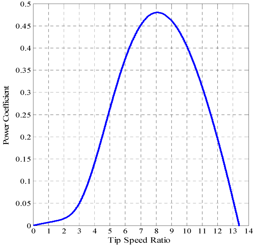
R is the radius of blade (m). The relation between
Cp and
λ when
β equal zero degree is shown in
Figure 2. It can be noticed that the optimum value of
Cp is about 0.48 for
λ equal 8.1. Maximum power extraction from wind turbine can be achieved when the turbine operate at maximum
Cp (
Cp-opt). Therefore, it is necessary to adjust the rotor speed at optimum value of tip speed ratio (
λopt) with wind speed variation.
Figure 2.
The relation between power coefficient (Cp) and tip speed ratio (λ).
Figure 2.
The relation between power coefficient (Cp) and tip speed ratio (λ).
Using (1) and (3), the optimum output power from wind turbine can be written as:
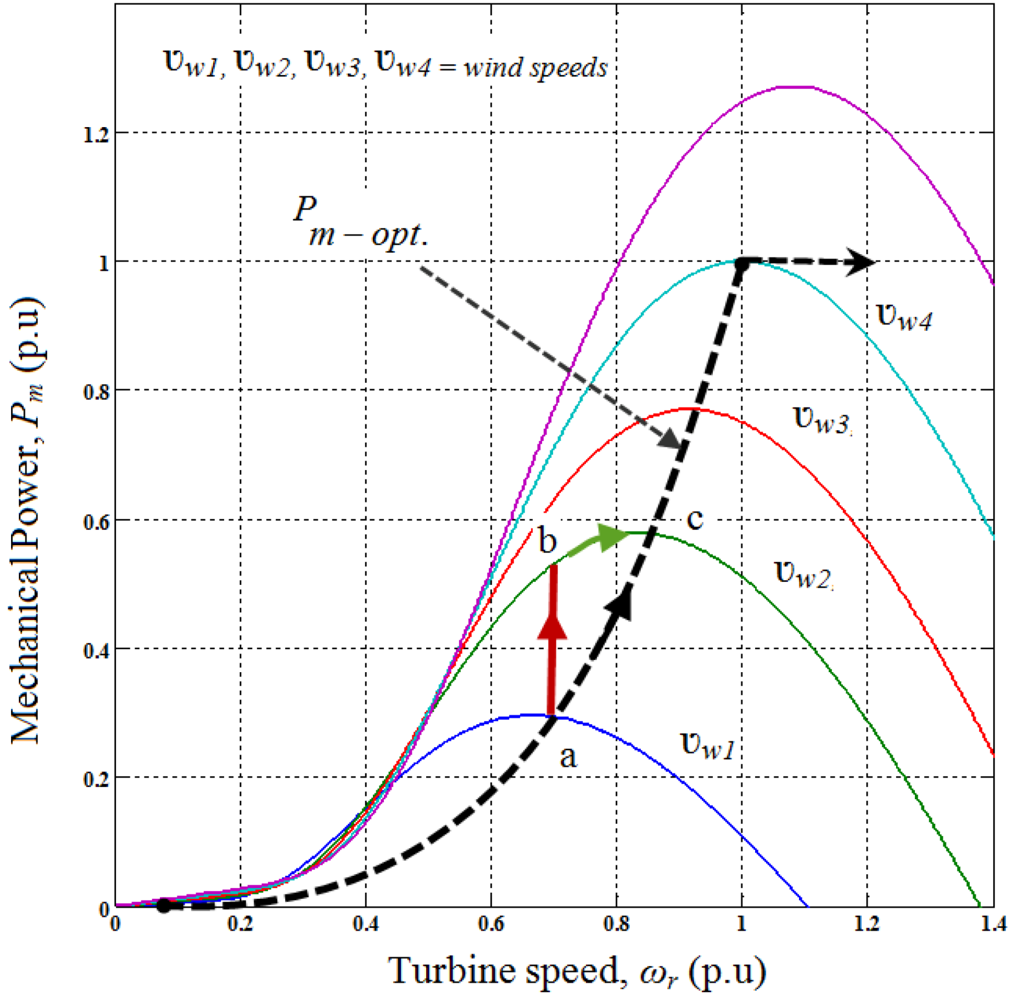
Figure 3 indicates that the mechanical powers generated by the turbine as a function of rotor speeds for different wind speeds. The maximum power extraction within the allowable range can be achieved if the controller can properly follow the optimum curve with variation of wind speed.
The generator side converter (a single switch three phase mode rectifier) is controlled to extract maximum power from available wind turbine power. Hence, the wind turbine can produce maximum power when the turbine operates at optimum value of Cp (Cp-opt). So it is necessary to adjust the rotor speed at optimum value of the tip speed ratio (λopt).
Figure 3.
The relation among mechanical powers generated and rotor speeds for different wind speeds.
Figure 3.
The relation among mechanical powers generated and rotor speeds for different wind speeds.
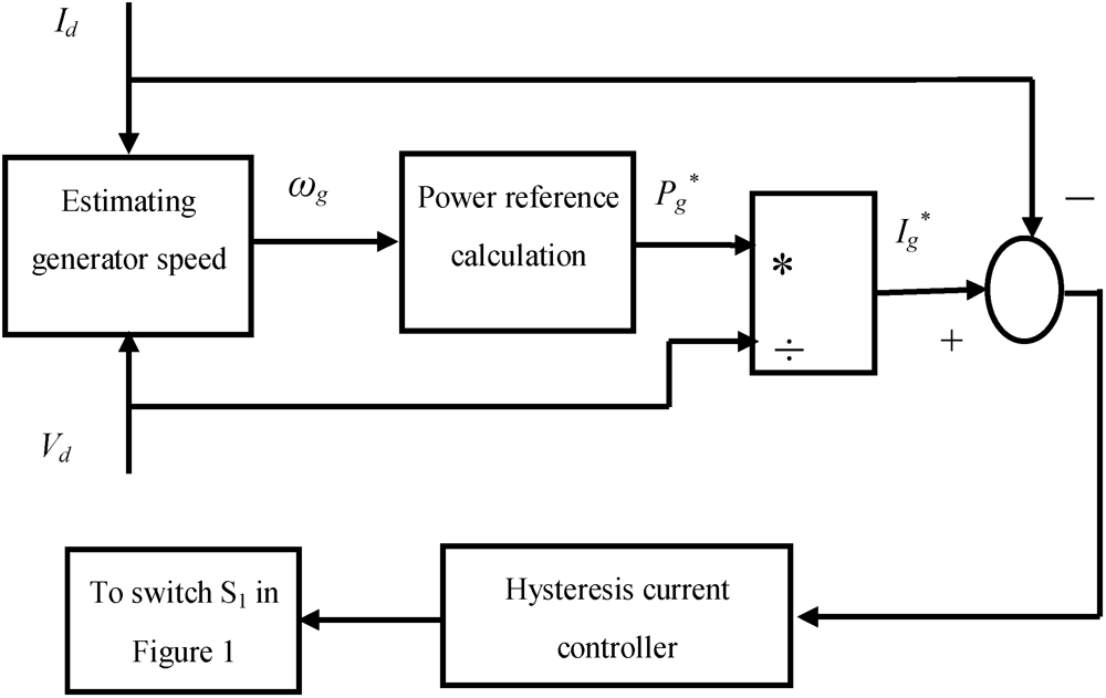
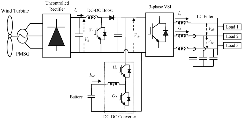
The structure of the proposed control strategy of the switch mode rectifier is shown in
Figure 4. The objective of this control is to control the duty cycle of DC-DC boost switch
S1 which is shown in
Figure 1 to extract maximum power from available wind power. The control algorithm includes the following steps:
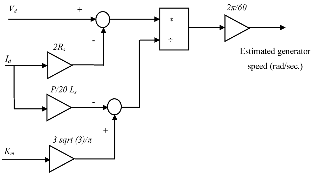
Estimate generator speed, ωg
Generator speed of PMSG can be estimated by measuring the average output voltage
Vd and current
Id of the uncontrolled bridge rectifier and by knowing the parameters of used PMSG in this paper which are given in
Table 1. [
20].
The relation among generator speed, PMSG parameters,
Vd and
Id is governed by (7).
where
ωg is the generator speed in (rad/second).
Figure 5 gives a configuration of (7) in MATLAB/ SIMULINK. The generator speed (
ωg) equal rotational speed (
ωr) where there is no gearbox between wind turbine and PMSG.
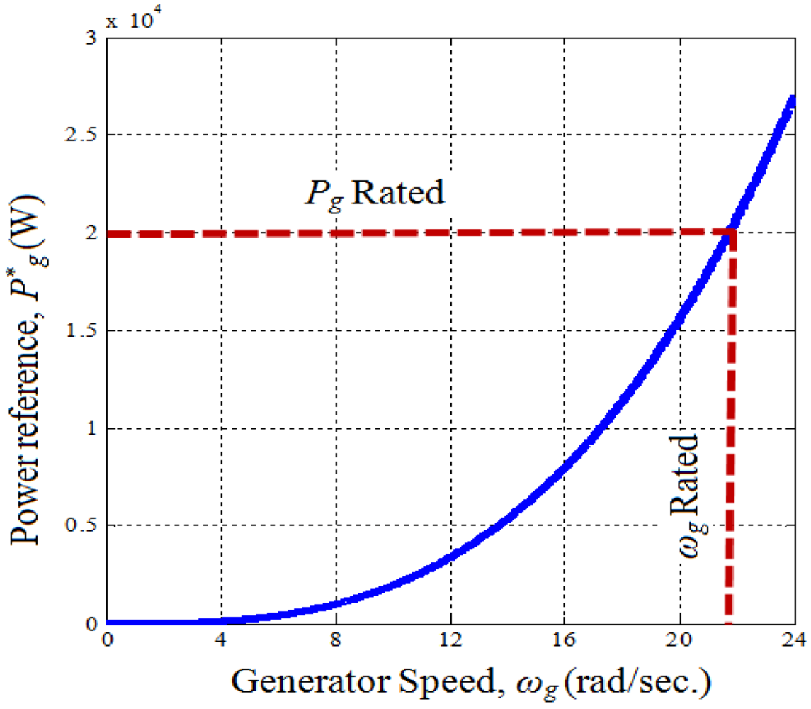
Determine the reference power as shown in
Figure 6, which describes the relation between the generator reference power and the generator speed, using (8).
This reference power is then used to calculate the reference DC current as indicted in (9).
The error between the reference DC current and measured DC current is used to adjust the duty cycle of the DC-DC boost converter to operate the generator speed at optimum speed through a hysteresis current controller to extract maximum power from wind turbine.
Table 1.
Parameters of permanent magnet synchronous generator.
Table 1.
Parameters of permanent magnet synchronous generator.
| Parameter name | Value |
|---|
| Rated output power | Pr = 20 kW |
| Rated mechanical speed | Nr = 211 rpm |
| Number of poles | Pole ( p) = 36 |
| Peak line-to-neutral back emf in no-load | ENL = 295.6 V |
| Stator winding resistance | Rs = 0.17640 Ω |
| Stator leakage inductance | Ls = 4.48 mH |
| Peak line-to-neutral back emf constant | Km = 1.4 V/rpm |
Figure 4.
The generator side converter control strategy.
Figure 4.
The generator side converter control strategy.
Figure 5.
Estimating of permanent magnet synchronous generator speed, ωg (rad/second).
Figure 5.
Estimating of permanent magnet synchronous generator speed, ωg (rad/second).
Figure 6.
Generator power reference versus generator speed.
Figure 6.
Generator power reference versus generator speed.
To describe the control function, considering
Figure 2. If the PMSG operating at point “a” and wind speed increases from υ
w1 to υ
w2 (point “b”), the additional power causes the PMSG to accelerate also causes difference between reference DC current and measured DC current, this difference operate to adjust the duty cycle of DC-DC boost converter to achieve optimum speed of the PMSG
ωg which attain maximum power extraction. Finally, the generator will reach the point “c” where the difference between reference DC current and measured DC current is within the bandwidth of the hysteresis current controller. A similar situation occurs when the wind speed decreases.
In this proposed strategy, there is no need to measure wind and generator speed using mechanical sensors which lead to inaccurate measurement.
4. DC-DC Bidirectional Converter Control
Battery storage system is essential for a stand-alone wind energy supply system to maintain the balance between the generated power from wind turbine and required load power through charge/discharge energy to/from this storage system. In this paper, the batteries bank is connected to the DC-link voltage through a DC-DC bidirectional buck-boost converter; the control of this converter can maintain the DC-link voltage at constant value as a reference value in addition to charge/discharge current to/from the batteries bank according to the required load power. The batteries bank voltage can be kept lower than the reference DC-link voltage (
Vdc*) and hence less number of batteries need to be connected in series. In the proposed system the batteries bank voltage is kept at about 300 V while
Vdc* = 690 V. In this paper the rating of the batteries bank, considering 60% depth of discharge (DOD), is decided based on the assumption that even when the wind power is zero it should be able to supply power to the load of a 15 kW for approximately an hour. The calculation of the battery rating is
Hence, 85 Ahr, 12 V battery rating is considered and therefore, twenty five numbers of batteries are required to connect in series.
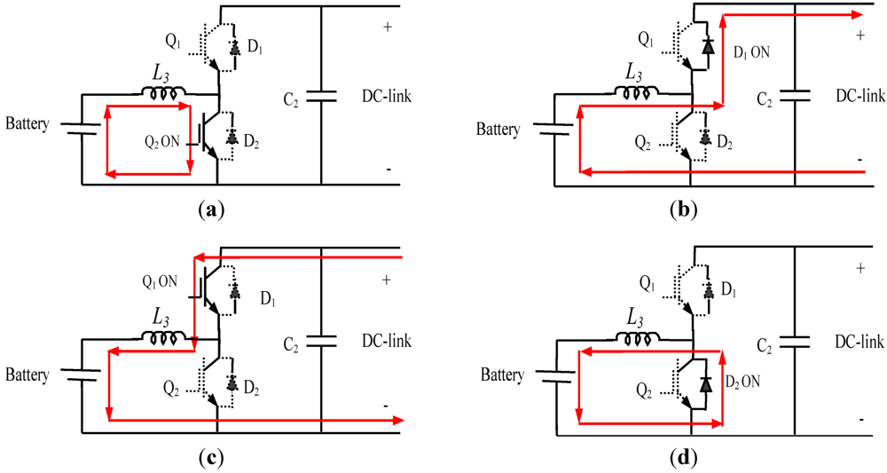
The DC-DC bidirectional buck-boost converter shown in
Figure 1 is operated in continuous conduction mode. The IGBTs Q
1 and Q
2 are switched in such a way that the converter operates in steady state with four sub intervals. The circuit operations in steady state for these different intervals are elaborated below:
Interval 1 (Q
2 ON); in this interval the lower switch Q
2 is turned ON and the upper switch Q
1 is turned OFF with diode D
1, D
2 reverse biased as shown in
Figure 7(a). During this interval the converter operates in boost mode and the inductor is charged and current through the inductor increases.
Interval 2 (D
1 ON); during this interval both switches Q
1 and Q
2 are turned OFF. The diode D
1 of the upper switch Q
1 starts conducting as shown in
Figure 7(b). The converter in this case supplies power to the DC-link voltage.
Interval 3 (Q
1 ON); the upper switch Q
1 is turned ON and the lower switch Q
2 is turned OFF with diode D
1, D
2 reverse biased as shown in
Figure 7(c). During this interval the converter operates in buck mode and transfer power to the batteries bank.
Interval 4 (D
2 ON); during this interval both switches Q
1 and Q
2 are turned OFF, the diode D
2 of the lower switch Q
2 starts conducting as shown in
Figure 6(d).
Figure 7.
Converter operation modes. (a) Iinterval 1; (b) Interval 2; (c) Interval 3;(d) Interval 4.
Figure 7.
Converter operation modes. (a) Iinterval 1; (b) Interval 2; (c) Interval 3;(d) Interval 4.
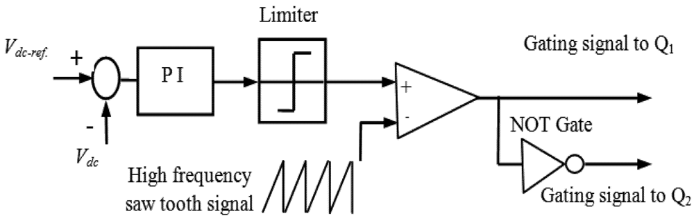
The control strategy of the DC-DC bidirectional buck-boost converter uses a PI controller to regulate the output DC voltage at a reference value is shown in
Figure 8. In this control technique, the DC voltage
Vdc is sensed and compared with the reference DC voltage
Vdc_ref.. The error signal is processed through the PI controller. The output signal is the duty cycle of the switches Q
1 or Q
2 according to the case of charging or discharging. Where, the parameters of the PI controller are obtained by using Zeigler Nichols tuning method.
Figure 8.
The DC-DC bidirectional converter control strategy.
Figure 8.
The DC-DC bidirectional converter control strategy.
The presence of inductor in batteries bank side results low ripple current which achieves higher efficiency and longer lifetime.
5. Load Side Converter Control
The load side converter, a three phase voltage source inverter, is used as interface between DC-link voltage and the load. Unwanted high frequency harmonics which are generated from load side voltage source inverter based on the switching frequency. This unwanted high frequency can be eliminated by using a simple passive LC filter to prevent the problems in power quality at the customer load.
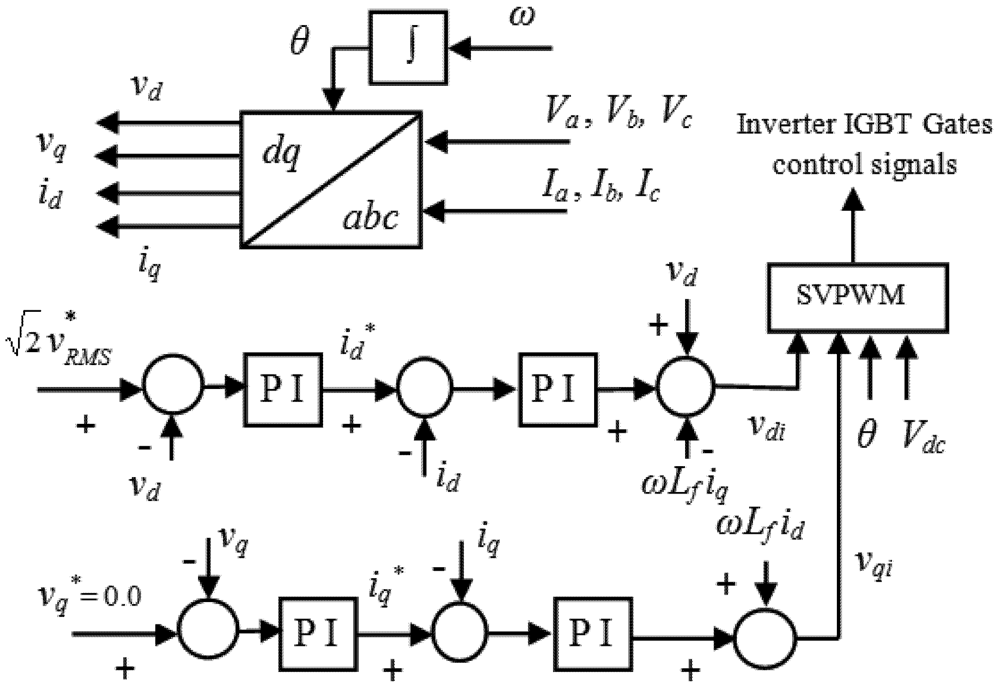
The load side voltage source inverter control is responsible to regulate the voltage and frequency at the customer load. In the stand-alone wind energy systems, there is no grid, the output voltages should be controlled in terms of amplitude and frequency. Vector control strategy is used to control the output load voltage during variation of required load power or wind speed.
In this paper, the specified load voltage frequency and RMS value of output phase voltage are 50 Hz and 220 V, respectively. The voltages Va, Vb, Vc and the currents Ia, Ib, Ic should be measured and transformed from stationary abc reference frame to rotating dq reference frame using chosen electrical load voltage frequency.
The voltage equations using
dq transformation in the rotating reference frame are:
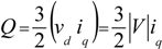
So, the active and reactive power can be calculated by using the
dq transformation and given by:
If the reference frame is
vq = 0 and
vd = │
V│, the equations for active and reactive power will be:
Therefore, active and reactive power can be controlled by controlling direct and quadrature components, respectively. Also, in the case of resistive load
Vd* can be governed by:
where
V*RMS is the
RMS reference value of the output phase voltage. The PI controllers are used to regulate output load currents in the inner control loops and to regulate the output load voltages in the outer loops. Compensation terms are added to compensate the cross-coupling effect due to the output filter in the rotating reference frame.
Space vector PWM technique is used in the controller, because it increases the fundamental output voltage. In addition it reduces the harmonic contents in the output voltage.
The control strategy of the voltage source inverter to supply controlled voltage in terms of magnitude and frequency to the load is shown in
Figure 9.
Figure 9.
The load side voltage source inverter control strategy.
Figure 9.
The load side voltage source inverter control strategy.
6. Simulation Results
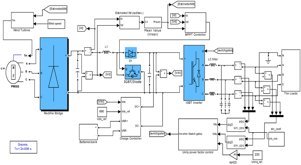
The proposed control strategy for a stand-alone variable speed wind energy supply system is simulated in MATALB/SIMULINK under different operating conditions.
Figure 10 shows the simulation block diagram for the system.
Figure 10.
Simulation block diagram.
Figure 10.
Simulation block diagram.
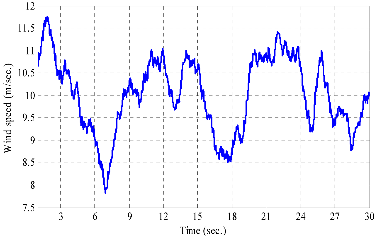
The variation in wind speed that occurs on a wind turbine is shown in
Figure 11 to observe the performance of control strategy under wind speed variation.
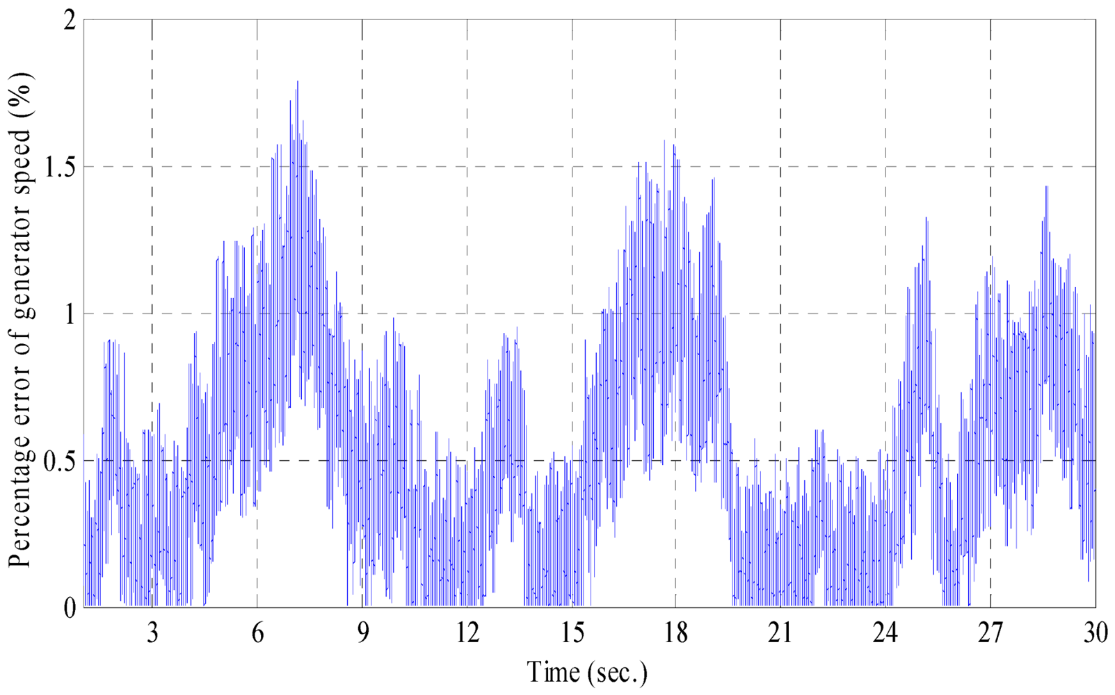
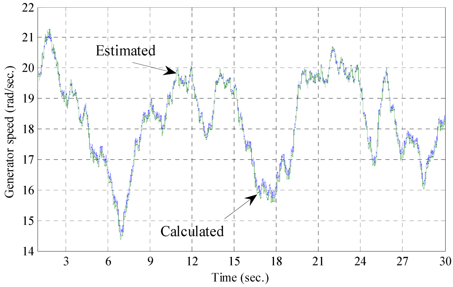
Figure 12 shows that the estimated and calculated generator speed where it varies with changing wind speed. The percentage error between the calculated and estimated generator speed is found less than 2% as shown in
Figure 13.
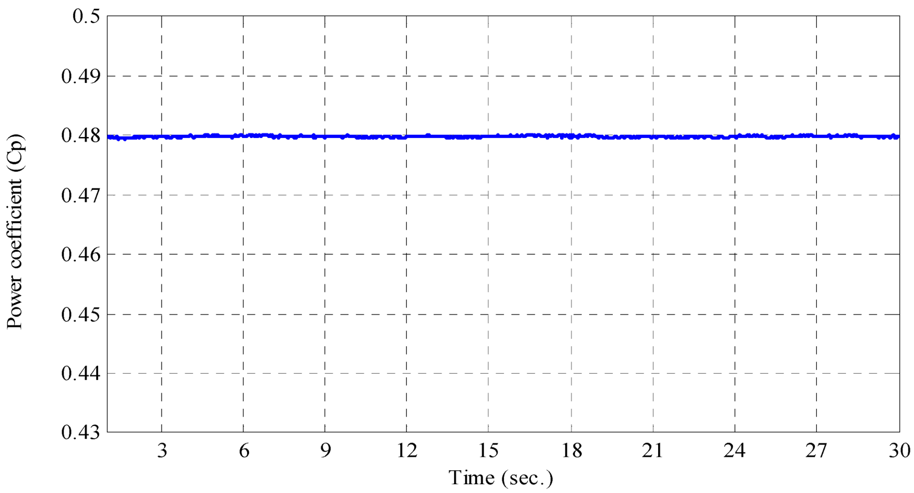
Figure 14 shows that the value of power coefficient
Cp, it is clear that the simple sensorless control technique works well where the value of power coefficient is kept at its optimum value which equals 0.48 with wind speed and load variation to extract maximum power from available wind turbine power.
Figure 11.
Wind speed variation (m/second).
Figure 11.
Wind speed variation (m/second).
Figure 12.
Estimated and calculated generator speed (rad/second).
Figure 12.
Estimated and calculated generator speed (rad/second).
Figure 13.
Percentage error of generator speed (%).
Figure 13.
Percentage error of generator speed (%).
Figure 14.
Power coefficient (Cp).
Figure 14.
Power coefficient (Cp).
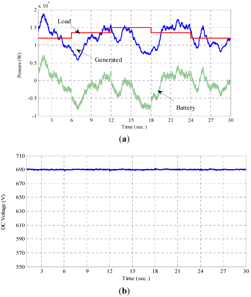
Figure 15 demonstrates the performance of DC-DC bidirectional buck-boost converter controller. It has been able to charge the batteries bank when the generated power is more than the required load power, and discharge the batteries bank when the required load power is more than the generated power. Also, to maintain the DC-link voltage at constant value which equals 690 V.
Figure 15(a) shows the generated, load, and batteries bank powers, where the maximum generated power is variable according to the wind speed variation. The required load power steps up at times 6.005 and 12.005 second (in worst time of change, where the instantaneous value of voltage and current of phase A is at maximum value) from 12 kW to 13.5 kW and from 13.5 kW to 15 kW, respectively. Also, it steps down from 15kW to 13.5 kW and from 13.5 kW to 12 kW at times 18.005 and 24.005 second, respectively (also in worst time of change). Batteries bank power changes (charge and discharge) to meet power balance of the system during required load and wind speed variation.
Figure 15(b) shows the DC-link voltage which is maintained at constant value at 690 V.
Figure 15.
The performance of DC-DC bidirectional converter controller. (a) Generated, load, and batteries bank powers; (b) DC-link voltage.
Figure 15.
The performance of DC-DC bidirectional converter controller. (a) Generated, load, and batteries bank powers; (b) DC-link voltage.
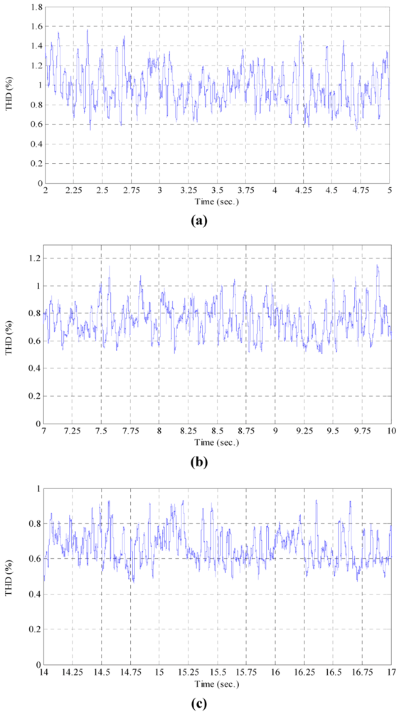
The total harmonic distortion (THD), in percentage, of the output load current for different required load power situations is shown in
Figure 14. Where, the THD is less than 1.6% when the required load power is 12 kW, the THD is less than 1.2% when the required load power is 13.5 kW, and the THD is less than 1.0% when the required load power is 15 kW as shown in
Figure 16(a–c), respectively.
Figure 16.
The total harmonic distortion (THD) for the output current for different load situations. (a) The THD for the output current when the required load power is 12 kW; (b) The THD for the output current when the required load power is 13.5 kW; (c) The THD for the output current when the required load power is 15 kW.
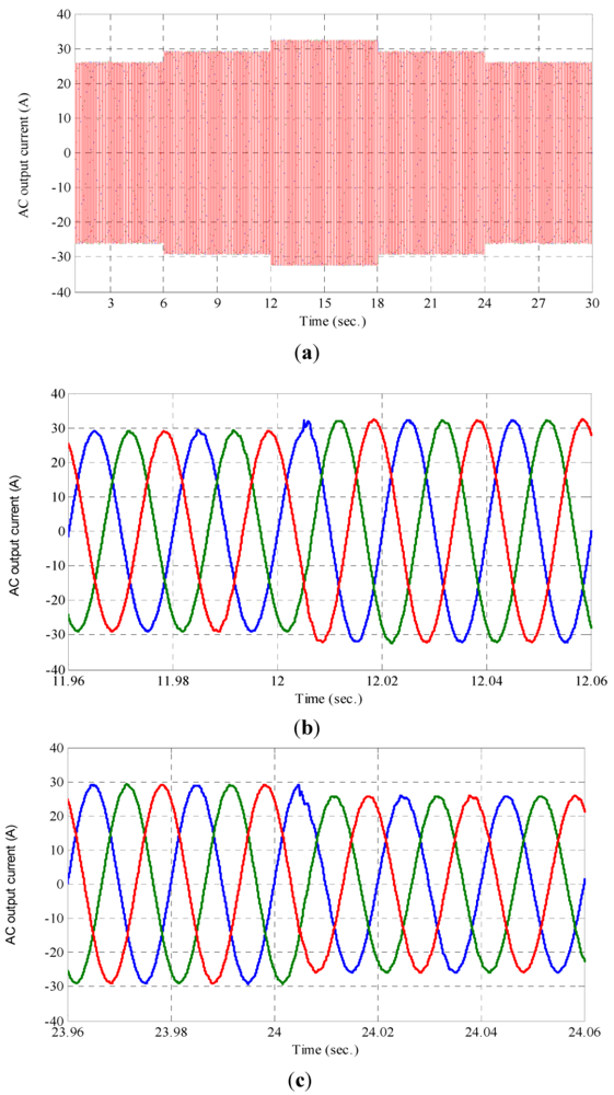
Figure 17(a) shows that the output load current responses with a long time simulation.
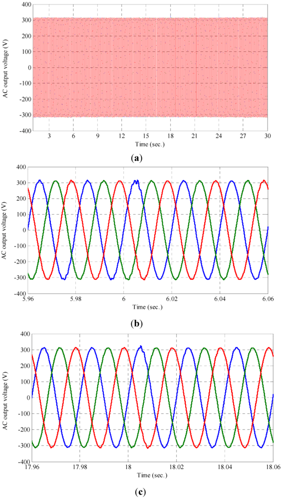
Figure 17(b,c) show the output load current at the instant of step up of required load power at time 12.005 seconds and step down of required load power at time 24.005 seconds, respectively. The output load voltage responses for all simulation time, output load voltage at the instant of step up of required load power at time 6.005 seconds and step down of required load power at time 18.005 seconds are shown in
Figure 18(a–c), respectively.
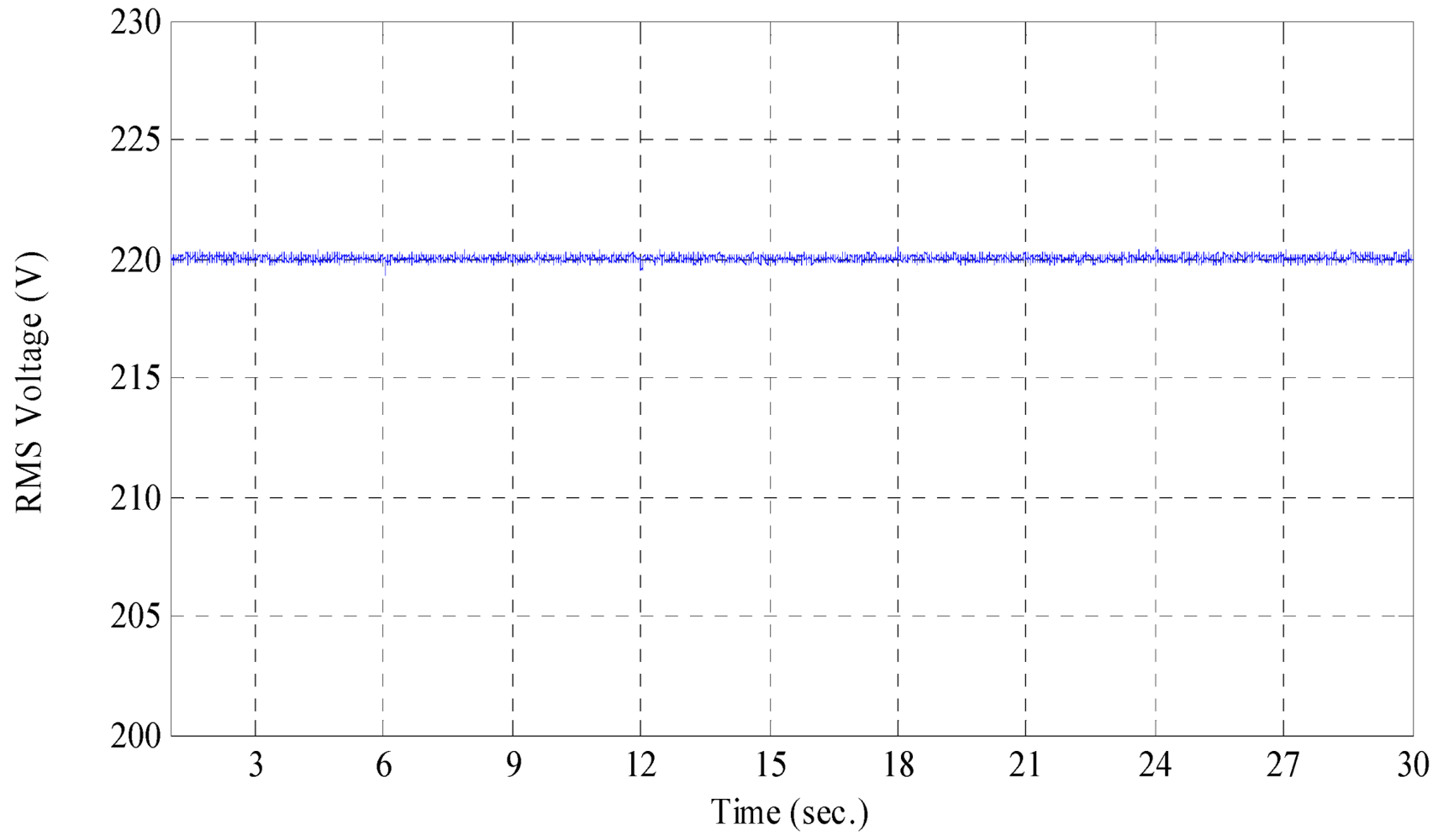
Figure 19 shows the
RMS value of output phase voltage, where it is maintained at 220 V as a reference. It can be seen that the control of the voltage source inverter works well under wind speed and required load power variation.
Figure 17.
Output load currents response with change in required load power. (a) AC output load currents thoughout the time simulation; (b) Load currents at the instant of step up load power at time = 12.005 second; (c) Load currents at the instant of step down load power at time = 24.005 second.
Figure 17.
Output load currents response with change in required load power. (a) AC output load currents thoughout the time simulation; (b) Load currents at the instant of step up load power at time = 12.005 second; (c) Load currents at the instant of step down load power at time = 24.005 second.
Figure 18.
Output load voltages response with change in required load power. (a) AC output load voltages throughout the time simulation; (b) Load voltages at the instant of step up load power at time = 6.005 second; (c) Load voltages at the instant of step down load power at time = 18.005 second.
Figure 18.
Output load voltages response with change in required load power. (a) AC output load voltages throughout the time simulation; (b) Load voltages at the instant of step up load power at time = 6.005 second; (c) Load voltages at the instant of step down load power at time = 18.005 second.
Figure 19.
RMS value of the output phase voltage (V).
Figure 19.
RMS value of the output phase voltage (V).


 ,
, 


