Article

Improved Permeate Flux of PVDF Ultrafiltration Membrane Containing PVDF-g-PHEA Synthesized via ATRP

Department of Chemical and Biomolecular Engineering, Yonsei University, 50 Yonsei-ro, Seodaemun-Gu, 120-749 Seoul, Korea
*
Author to whom correspondence should be addressed.
These authors contributed equally to this work.
Appl. Sci. 2015, 5(4), 1992-2008; https://doi.org/10.3390/app5041992
Submission received: 10 September 2015 / Revised: 8 December 2015 / Accepted: 14 December 2015 / Published: 21 December 2015
(This article belongs to the Special Issue Organo-Fluorine Chemical Science)

Abstract

:
Polyvinylidene fluoride (PVDF) ultrafiltration (UF) membrane combined with polyvinylidene fluoride-graft-2-hydroxyethyl acrylate (PVDF-g-PHEA) was fabricated via non-solvent induced phase separation (NIPS). In this study, PVDF-g-PHEA was synthesized via atom transfer radical polymerization (ATRP) method, and then synthesized graft copolymer was characterized using Fourier transform infrared spectroscopy (FTIR), nuclear magnetic resonance (NMR) and thermogravimetry analysis (TGA). Moreover, PVDF membranes containing graft copolymer (PVDF-g-PHEA) showed lower water contact angle value than pristine PVDF membranes. Macrovoid holes were also observed in cross sectional scanning electron microscope (SEM) image of PVDF membrane containing PVDF-g-PHEA. Accordingly, it was confirmed that these characteristics led PVDF membrane blended with graft copolymer has high final permeate flux and normalized flux compared to pristine PVDF membrane.

1. Introduction

Recently, as water shortage and pollution problems are becoming more serious, the importance of the water industry has become increasingly emphasized. Hence, membranes are receiving attention to play an important role in solving these water-related problems. Membranes have some advantages in comparison to traditional separation technologies such as coagulation, aggregation, and sedimentation which include convenience of control, excellent quality of processed water and ease of maintenance. Due to these advantages, membranes have been used for seawater desalination, sewage treatment, wastewater treatment, and drinking water production [1]. Membranes are divided into RO (reverse osmosis), NF (nanofiltration), UF (ultrafiltration), and MF (microfiltration) membranes, depending on usage. In particular, UF membranes make up a large part of the world membrane market and are used for wastewater treatment, and food concentration and purification. Polysulfone (PS), polyethylene (PE), polyethersulfone (PES), polyvinylidene fluoride (PVDF), and polyvinyl chloride (PVC) have been used in the production of membranes [2]. PVDF is an especially beneficial material to prepare membranes because of its strong chemical resistance and mechanical properties [3,4,5,6,7,8]. Due to these advantages, PVDF has been widely used to fabricate membranes. However, PVDF has a critical disadvantage; it is susceptible to fouling during treatment of water containing humic acid which is a natural organic material (NOM). Since PVDF and NOM are hydrophobic, PVDF membranes easily absorb NOMs. As a result of filtration of NOM on PVDF membranes, its life is decreased. Hence, the improvement of PVDF membranes is recently a hot topic in membrane science. Among methods for improvement, blending with the graft copolymer in PVDF casting solution after synthesis of hydrophilic graft copolymer has been reported by researchers, in order to prepare PVDF membranes with improved flux during filtration of humic acid (HA) [9,10]. However, it has not been fully clarified that successful PVDF-g-PHEA (Poly(vinylidene fluoride)-graft-poly(hydroxyethyl acrylate)) synthesis and blending with synthesized PVDF-g-PHEA additive in PVDF casting solution leads to improved hydrophilicity, resulting in improved ability during membrane formation. If the PVDF membrane has hydrophilic properties resulting from PVDF-g-PHEA, it will absorb less NOMs than the original PVDF membrane. Consequently, permeate flux can be enhanced by improving qualities of membrane material such as increased hydrophilicity [11].
Nowadays, ATRP (Atomic Transfer Radical Polymerization), one of the grafting methods, is used to develop membranes to include improvement of permeate flux. ATRP is utilized for polymerization of polymers containing halogen atoms and hydrophilic polymers containing styrene, (meth)acrylates, (meth)acrylamides and acrylonitrile structures as the simple polymerization method which does not require strict experiment environment, comparing to other traditional polymerization methods [12,13]. In advance, numerous graft copolymers such as poly(vinylidene fluoride)-graft-poly(ethylene glycol) methyl ether methacrylate (PVDF-g-PEGMA) and poly(vinylidene fluoride)-graft-poly(oxyethylene methacrylate) (PVDF-g-POEM) were successfully made by using ATRP method [14,15]. Blending these graft copolymers with PVDF made membranes with improved permeate flux. HEA (Hydroxyethyl acrylate) is the chemical material which contains acrylate structure. Therefore, it is expected that HEA would be polymerized with PVDF successfully by ATRP method to make the membrane, including hydrophilicity. Nevertheless, it has not been fully reported to synthesize PVDF-g-PHEA by ATRP method. For this reason, synthesis of PVDF-g-PHEA and fabrication of membranes containing PVDF-g-PHEA will be useful for the field of membrane technology in order to improve flux performances.
This study proposes a method to synthesize PVDF-g-PHEA and prepare for PVDF UF membrane with improved permeate flux during filtration of HA solutions. In the research, the author successfully synthesized PVDF-g-PHEA, fabricated membranes by blending PVDF with the hydrophilic graft copolymer additive (i.e., PVDF-g-PHEA), and determined the characteristics of the resulting PVDF UF membranes.

2. Experimental Methods

2.1. Materials and Reagents

Polyvinylidene difluoride (PVDF) (Solef® 6020, Mw: 700,000 g/mol) was purchased from Solvay (Seoul, Korea). CuCl (copper chloride, 98.999 g/mol), HMTETA (1,1,4,7,10,10-hexamethyltriethylenetetramine, 230.39 g/mol), DMSO-d6 (deuterated dimethyl sulfoxide, 99.9%), N-methyl-2-pyrrolidone (NMP) and HEA (2-hydroxyethyl acrylate, 116.12 g/mol) were purchased from Sigma Aldrich, Yongin, Gyeonggi-do, Korea. Humic acid (Mw: 1000–300,000 Da) was used to measure fouling of the membranes. The stock solution was made by mixing humic acid with distilled water and set at pH 7.67. The stock solutions of six and 20 ppm were kept in the class bottle.

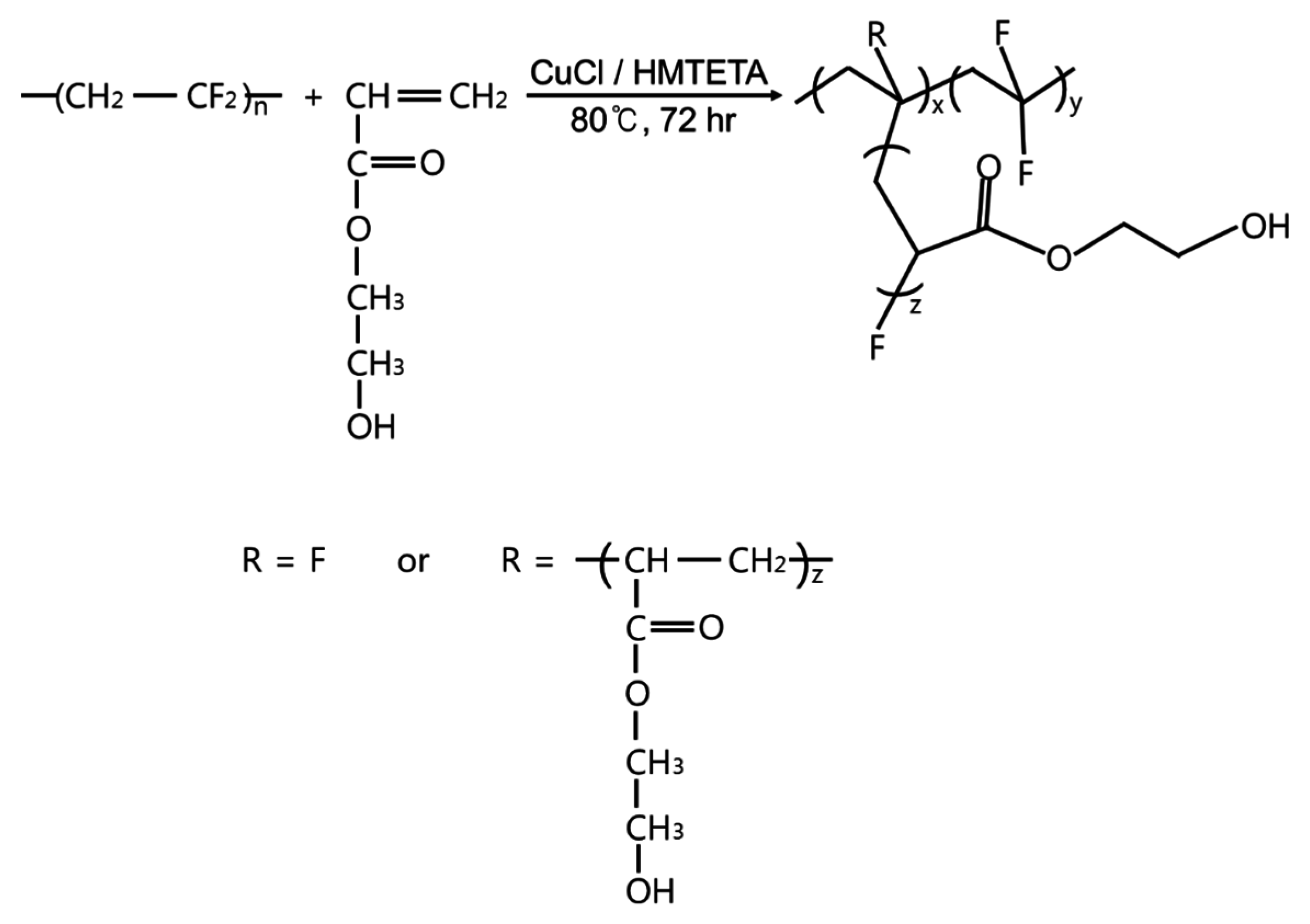
2.2. Synthesis of PVDF-g-PHEA Copolymer

Figure 1 shows procedure of PVDF-g-PHEA synthesis. PVDF (5.2 g) was dissolved in NMP (100 mL) at 80 °C for 24 h, and then HEA (15.8 g), CuCl (0.4 g) and HMTETA (1.0 mL) were added. Nitrogen gas was injected for 30 min and separate flasks were placed inside oil bath at 80 °C for 72 h. The catalyst (CuCl) stimulated fluorine (F) to be removed and HEA to be attached on the site of the fluorine. PVDF-g-PHEA, the graft copolymer, was separately purified by soaking in methanol and DMSO. Afterwards, the PVDF-g-PHEA was dried in vacuum dry oven at 62 °C for 24 h. It is should be noted that PHEA homopolymer dissolves in methanol or water.
Figure 1. Polymerization process of PVDF-g-PHEA.
Applsci 05 01992 g001

2.3. Preparation of Membranes

Table 1 shows chemical compositions for different four types of membranes. In order to prepare for PVDF membranes containing PVDF-g-PHEA via non-solvent induced phase separation (NIPS) [16], PVDF was dissolved in DMSO with the graft copolymer additive in vials at 80 °C for 24 h. To fabricate PVDF pristine membranes, PVDF was dissolved in DMSO in vials at 80 °C for 24 h. Pore size of the membranes was controlled by PVDF content for more accurate flux performance according to the experiment studied by Woo et al. [17]. The solutions were cast on nonwoven fabric and then immersed into the water bath. The temperature of water bath was set to 25 °C. After 5 min, the membranes were rinsed and dried outside for 24 h.
Table 1. Membrane compositions.
MembranesPVDF(g)DMSO(g)PVDF-g-PHEA (g)
A-19.5 g90.50 g0.0 g
B-110.0 g90.00 g0.0 g
A-29.0 g90.40 g0.6 g
B-29.0 g90.10 g0.9 g

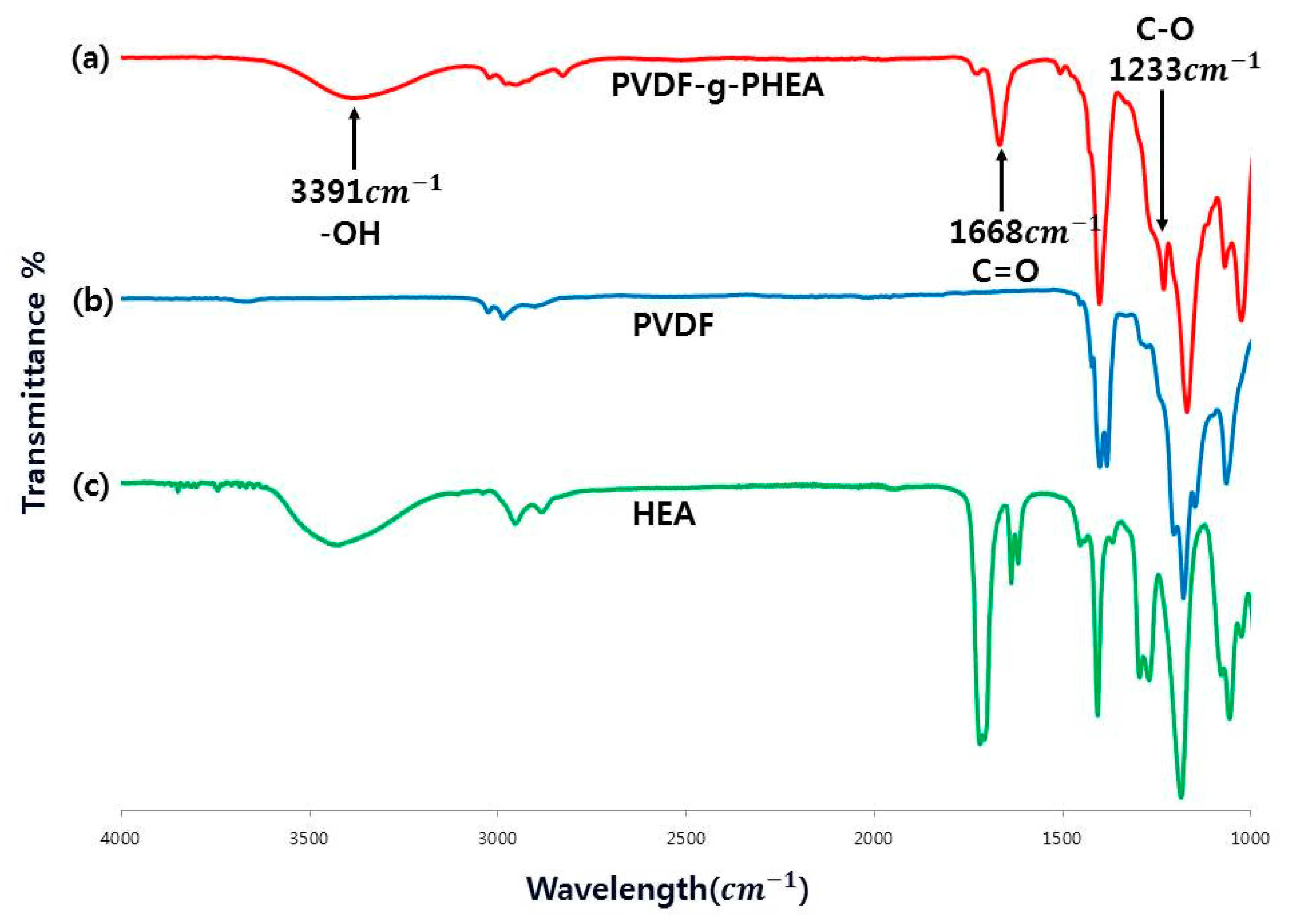
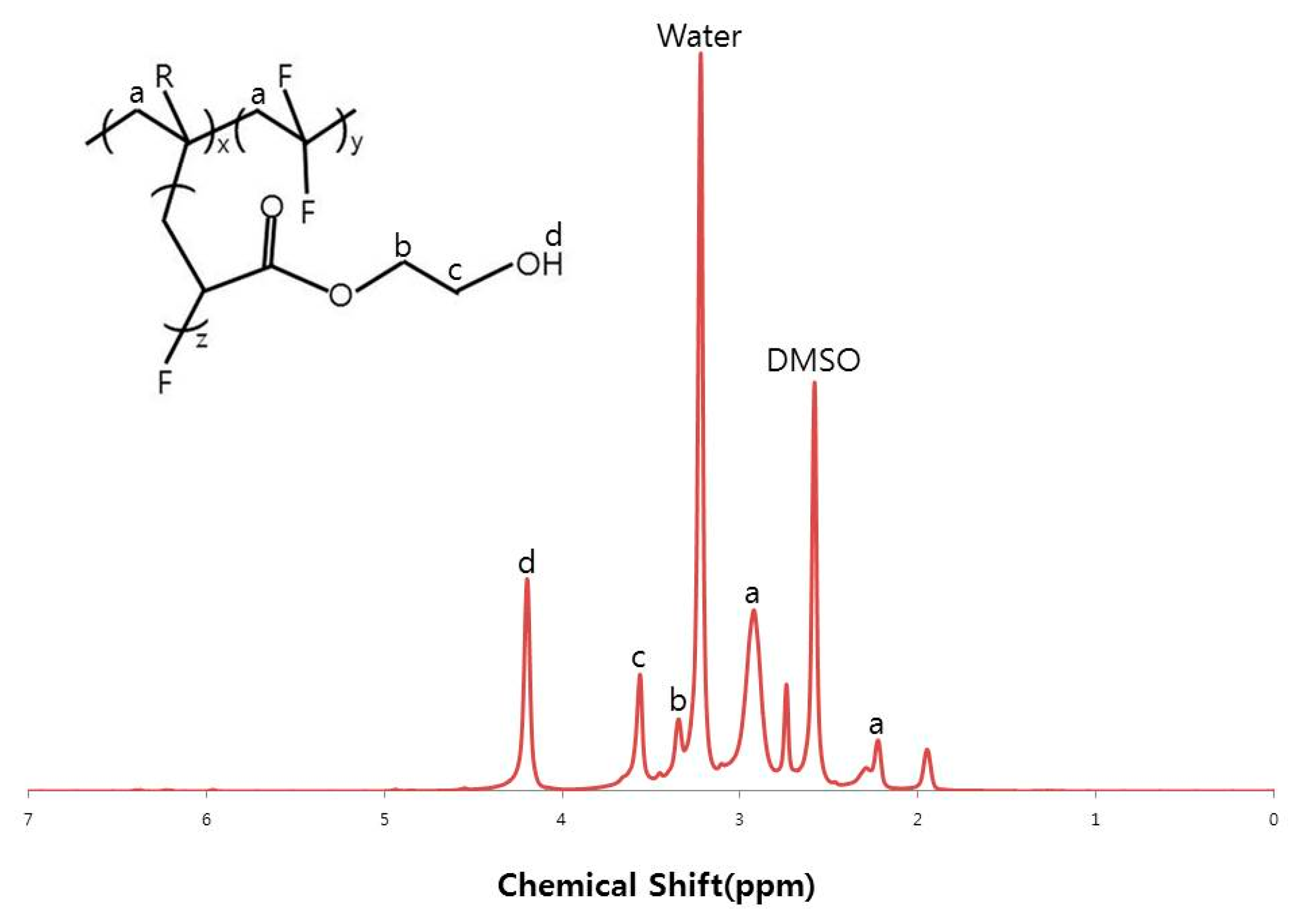
2.4. FT-IR and NMR Analysis

The synthesized graft copolymer (i.e., PVDF-g-PHEA additive) was analyzed using FT-IR and NMR method to figure out if PVDF was synthesized with HEA correctly. An Excalibur series FT-IR spectrometer (Spectrum 100, Perkin-Elmer, Waltham, MA, USA) was used to express the structure of the graft copolymer. The range of FT-IR spectra was from 4000 cm−1 to 1000 cm−1. NMR spectrometer (Avance-600 Bruker, Rheinstetten, Germany) was used to investigate the grafting ratio of the graft copolymer. The range of NMR spectra was from 0 to 7 ppm.

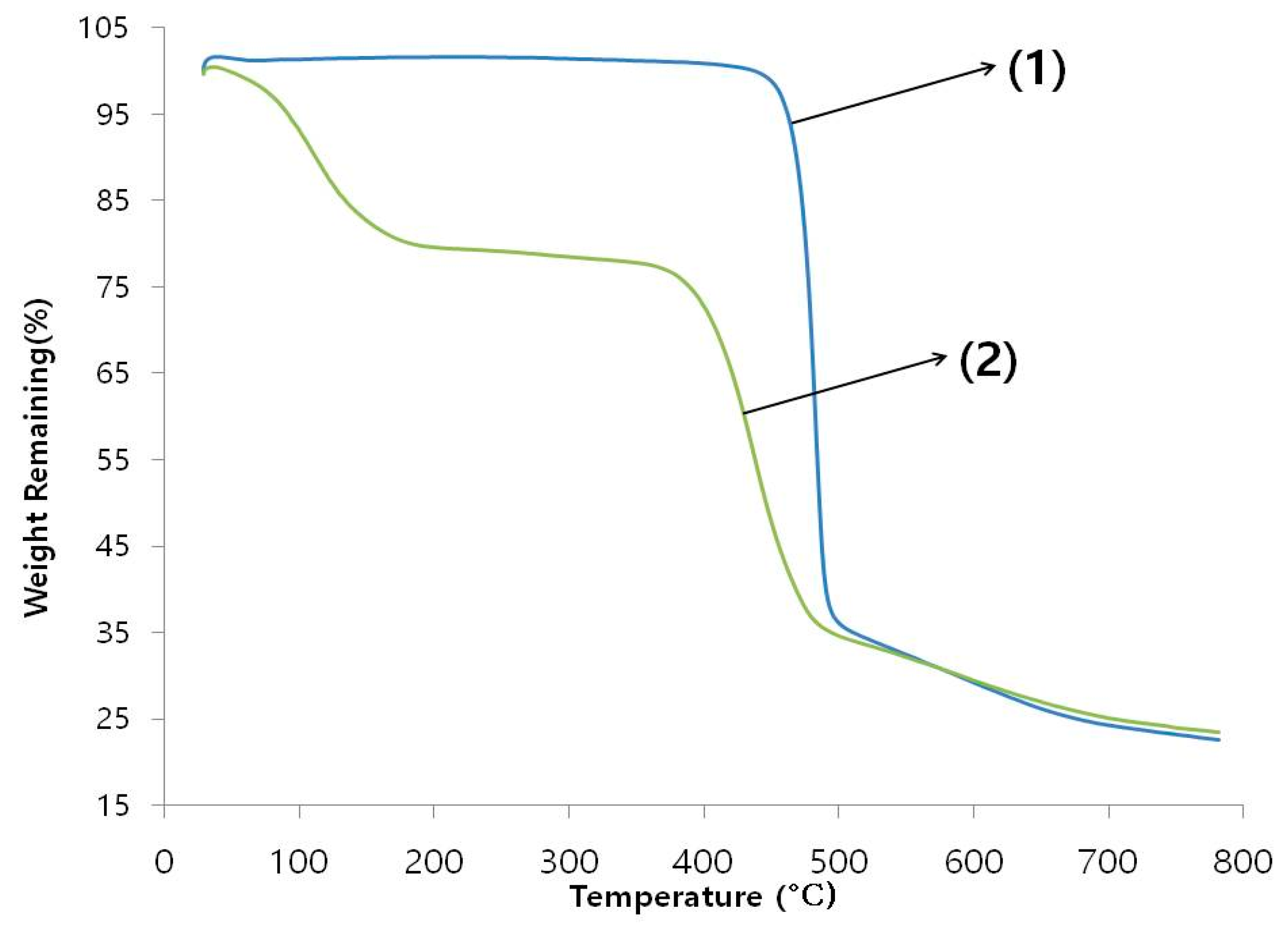
2.5. TGA (Thermogravimetric Analysis) Performance

The synthesized graft copolymer (i.e., PVDF-g-PHEA additive) was analyzed by using TGA to recognize the thermal stability. The range of heating sample was from 0 to 800 °C at 14 °C /min for 1 h by carrying nitrogen gas in simultaneous thermal analyzer (STA8000, PerkinElmer, Mount Berry, GA, USA).

3. Membrane Characterization

3.1. Contact Angle Analysis

To identify hydrophilicity of membranes, water contact angle analysis was introduced. Before measuring the water contact angle, the membranes were dried for 24 h at the room temperature. Distilled water was dropped on three different parts of the membrane surface three times from the water contact angle instrument (Phoenix 300, SEO, Suwon, Gyeonggi-do, Korea) and the water contact angle was measured immediately. Water contact angle values have been reported.

3.2. Pore Size Measurement

CFP (Capillary Flow Porometer, PMI, New York, NY, USA) was used to determine the pore size and the pore distribution. The membranes were cut into circular small slices and immersed in galwick liquid (surface tension: 15.9 dyn/cm1) for 24 h. After soaking membranes in galwick liquid enough, the membranes were placed inside the CFP to measure the pore size and pore distribution. Experiments were performed by flowing nitrogen (N2) gas. As time passed, bubble points, which mean the maximum pore size, were obtained. At the end, experimental values such as pore size and pore distribution have been obtained following this equation [3,17]:
D =   4 γ cos θ P
where D is the pore size, γ is the surface tension of galwick liquid, θ is contact angle of galwick liquid, and P is the pressure.

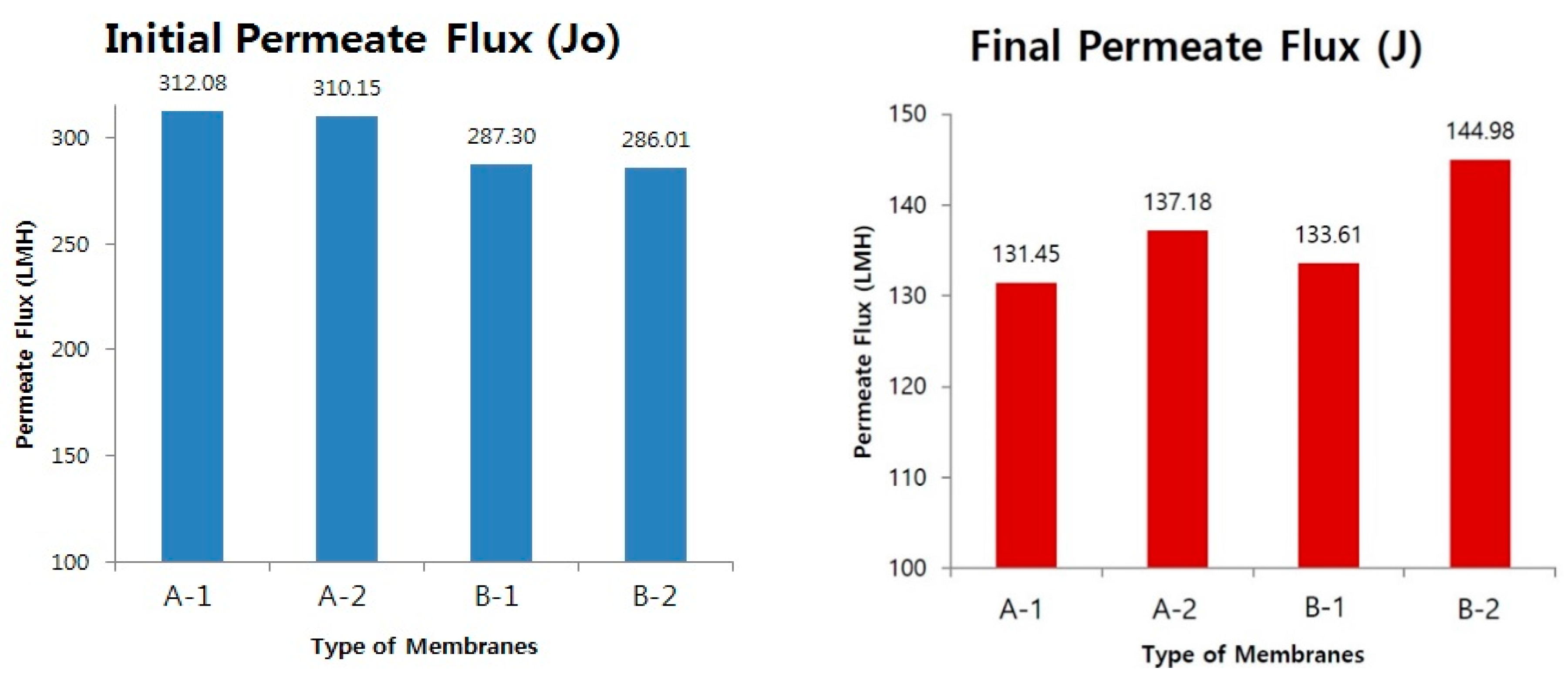
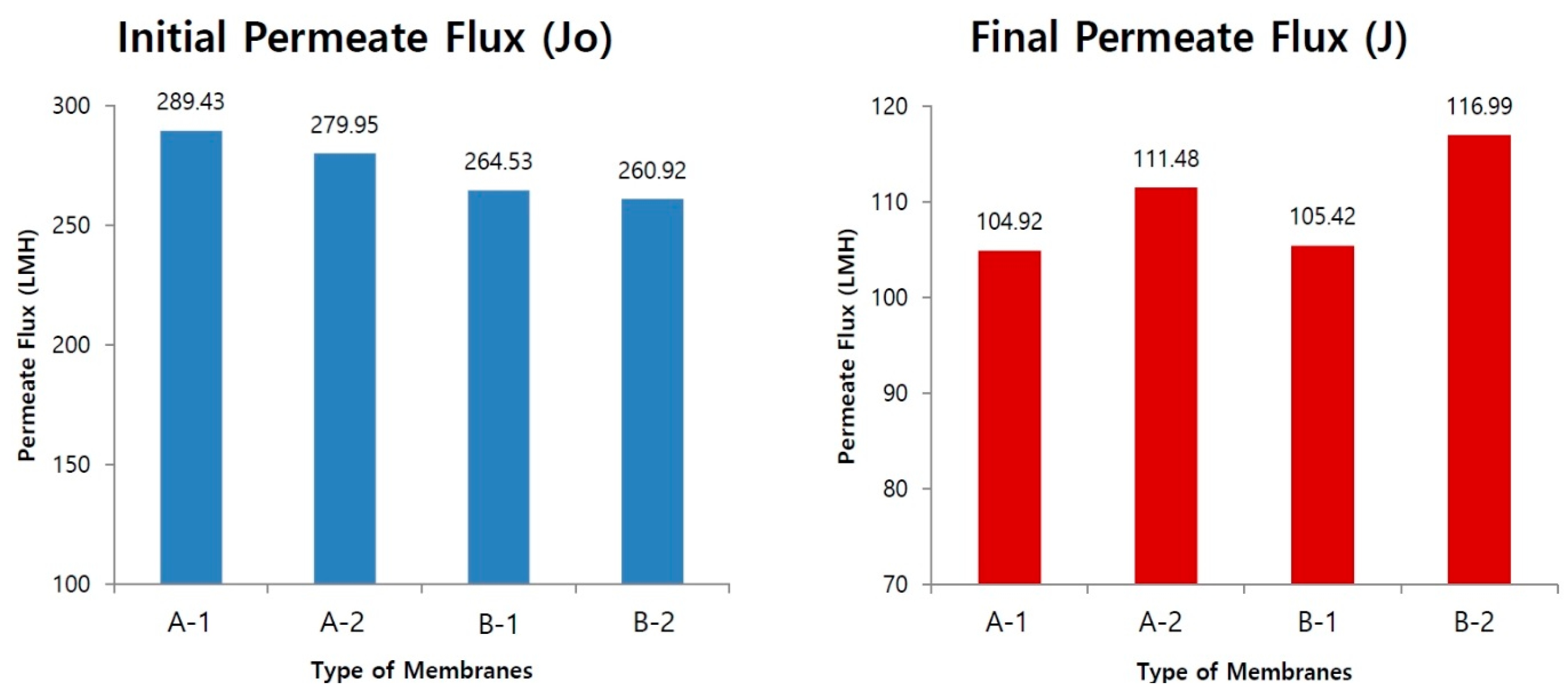
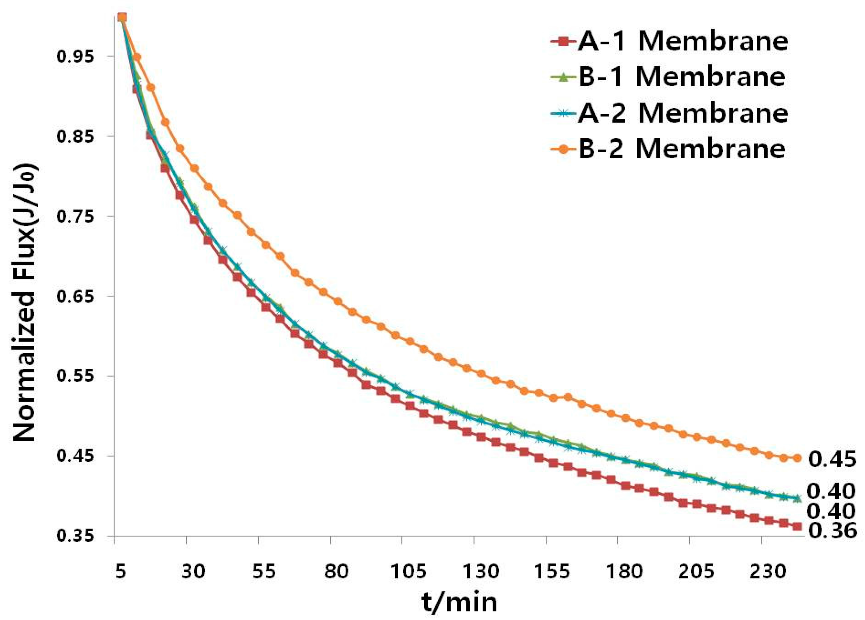
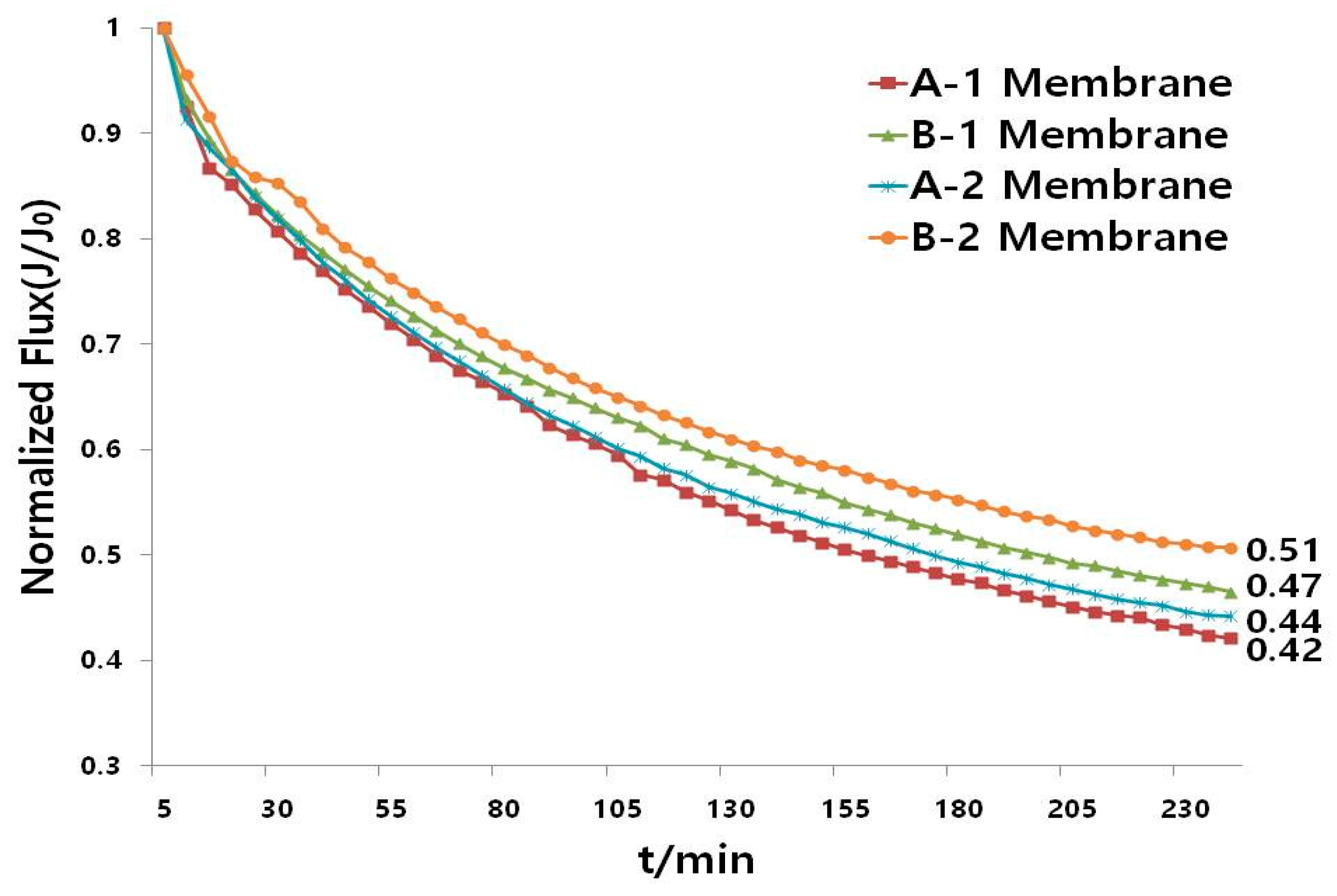
3.3. Flux Characterization

The flux of all membranes was measured at 1 bar of transmembrane pressure (N2 gas) and 25 °C of temperature with 400 rpm. Humic acid (Mw: 1000–300,000 Da) was chosen as the model for membrane fouling research. Six and 20 ppm HA solutions were used for the flux performance. HA solution was adjusted to pH 7.67 by addition of 0.1 M NaOH solution by using a pH meter (Orion DUAL STARTM, Thermo Fisher Scientific, Beverly, MA, USA). Prior to permeate flux performances, pure water flux was measured for 2 h. After permeating pure water into membranes, humic acid solution was run for 4 h to evaluate membrane performance. Pure water flux and permeate flux of humic acid (six and 20 ppm) were evaluated by this equation:
J   ( L M H ) = V A T
where V was the volume of pure water and the humic acid permeated, A was the area of the membrane, and T was the time humic acid permeated. In the experiment, the area of the membrane was 0.00134 m2.

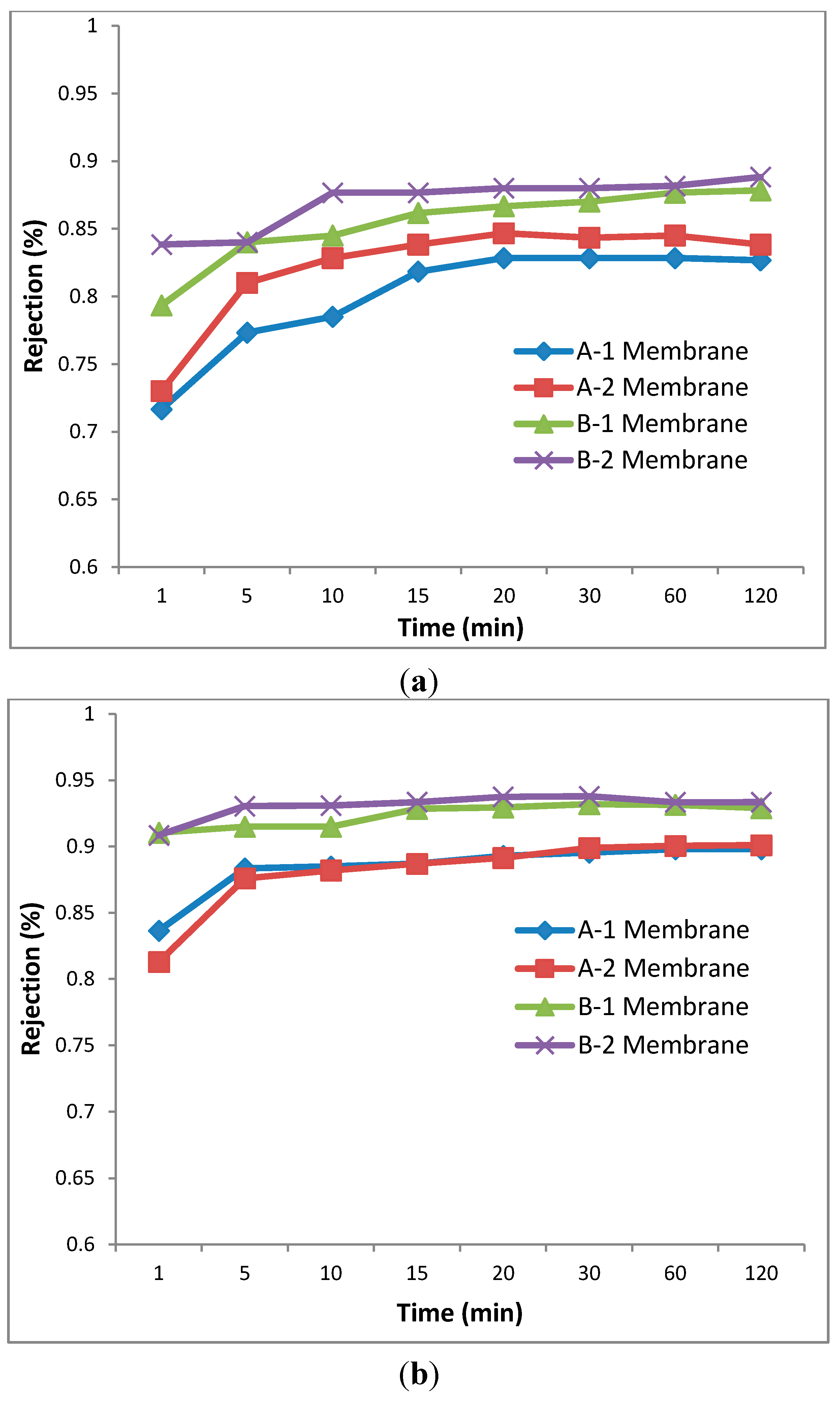
3.4. Humic Acid Rejection Test

Humic acid rejection test is the important method to measure capabilities of membranes. Six and twenty ppm HA solutions were used for humic acid rejection test. After pure water was filtrated through membranes, feed solution and filtrate solutions were put into cells. The humic acid concentration of feed solution and filtrate solutions was evaluated using the UV spectrophotometer (Shimadzu, UV-160A, Kyoto, Japan). 254 nm was used as the wavelength for measuring absorbance. [18] Percent of humic acid rejection was evaluated by this equation:
R(%) = 1 − (Cfiltrate/Cfeed)
where Cfiltrate was the concentration of filtrate solutions and Cfeed was the concentration of feed solution.

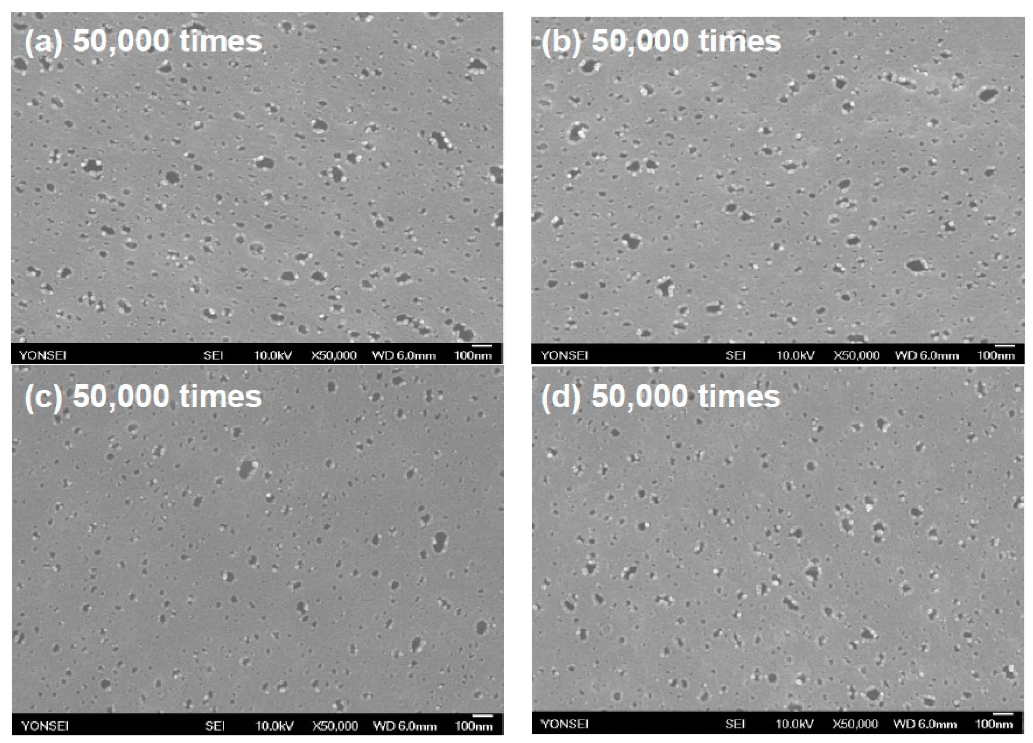
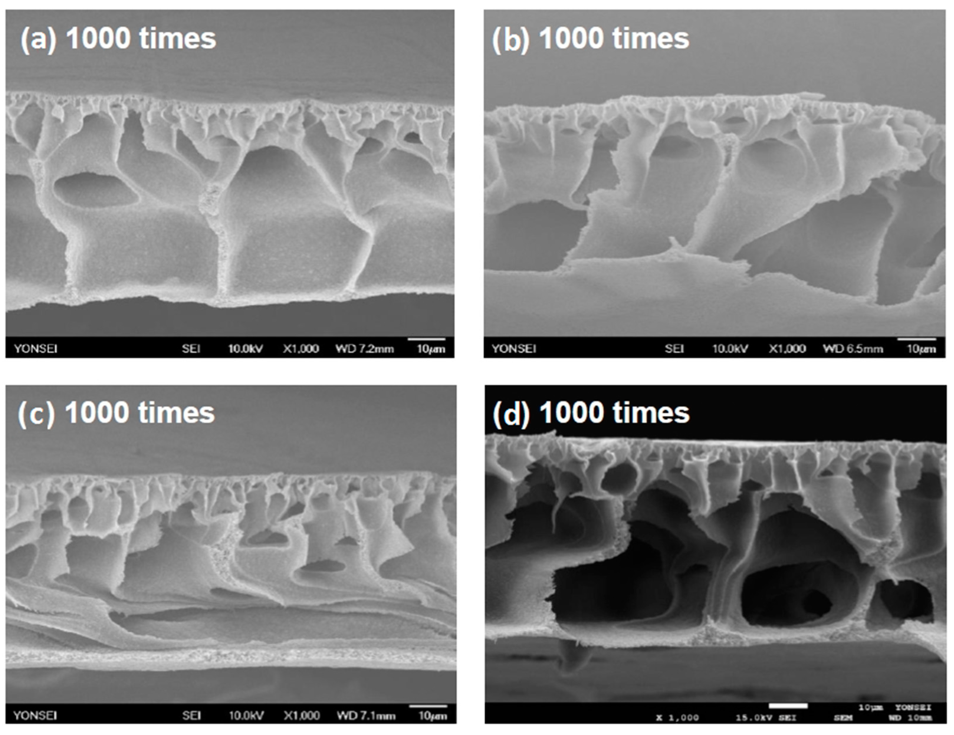
3.5. SEM (Scanning Electron Microscopy) Analysis

SEM (JSM-7100F, JEOL, Tokyo, Japan) was used to analyze the cross-sectional morphology and the pore structure of the membrane. The membranes were held by the pincette and divided into two small pieces to investigate the cross section of membranes. Before using SEM, the membranes were immersed in liquid nitrogen for 5 min to be frozen. The frozen membranes were coated with platinum (Pt) for 100 s. Coated membranes were investigated to analyze the pore structure and the cross-sectional morphology.

4. Results and Discussion

Analysis of PVDF-g-PHEA Copolymer
FT-IR spectra were measured to identify functional groups of the graft copolymer. Figure 2 shows the FT-IR spectra of graft copolymer which was synthesized for 72 h. The graft copolymer displayed wide transmittance bands at 3391 cm−1, pointing to hydroxyl group (i.e., –OH) of 2-hydroxyethyl acrylate. The strong transmittance bands also indicate that the graft copolymer has C=O (1668 cm−1), and C–O (1233 cm−1) structures of 2-hydroxyethyl acrylate [19].
Figure 2. FT-IR spectra of PVDF-g-PHEA.
Applsci 05 01992 g002
1H-NMR was measured by using 600 Hz NMR spectrometer with DMSO-d6 (Deuterated Dimethyl Sulfoxide, 99.9%, Sigma-Aldrich, Yongin, Gyeonggi-do, Korea) solution. Figure 3 indicates that the graft copolymer was synthesized successfully. The two high peaks indicate DMSO and water at 2.5 and 3.2 ppm, respectively. Two strong peaks indicate head-to-tail and head-to-head bonding of vinylidene fluoride at 2.9 and 2.3 ppm, respectively. Three strong peaks are protons connected to PHEA at 4.2, 3.5, and 3.3 ppm [19]. The grafting ratio can be calculated using the following equation: [20]
f PVDF = I a × 64 / 2 I a × 64 / 2 + I b × 116 / 2
f PHEA = I b × 116 / 2 I a × 64 / 2 + I b × 116 / 2
where I a   and I b are integral of PVDF and integral of PHEA, respectively. 64 and 116 represent the molar mass of PVDF and PHEA, respectively. As an evaluation result, the grafting ratio of PHEA in PVDF-g-PHEA was 22.6% in a mass basis.
Figure 3. 1H-NMR spectra of PVDF-g-PHEA copolymer.
Applsci 05 01992 g003
Figure 4. TGA graphs of (1) PVDF and (2) PVDF-g-PHEA.
Applsci 05 01992 g004
Figure 4 indicates TGA graphs of PVDF and PVDF-g-PHEA graft copolymer. PVDF started declining at approximately 446.4 °C. On the contrary, PVDF-g-PHEA graft copolymer showed decomposition step at 380.7 °C, indicating the decomposition of 2-hydroxyethy acrylate, and moisture for PVDF-g-PHEA was evaporated from about 30 to 100 °C. This result confirmed that PVDF-g-PHEA graft copolymer had smaller thermal stability than PVDF. However, PVDF-g-PHEA graft copolymer can thermally stand up to 380.7 °C [17].

5. Characterization of Membranes

5.1. Contact Angle Analysis

Measuring contact angle is one of the important and brief criteria to recognize the hydrophilicity of the membrane. Therefore, contact angle was measured to figure out the hydrophilicity of the membranes. After measuring several times, the average of contact angle values was calculated. As a result of measurement, contact angles of 9.5% and 10% PVDF pristine membranes were 68.6° and 68.0°, respectively. Contact angles of PVDF membranes blended with 0.6% and 0.9% copolymer (i.e., PVDF-g-PHEA) were 64.3° and 61.8°, respectively. It was shown that as the concentration of graft copolymer was higher, the membrane contact angle was decreased. In other words, more hydrophilic membrane could induce higher permeate flux.

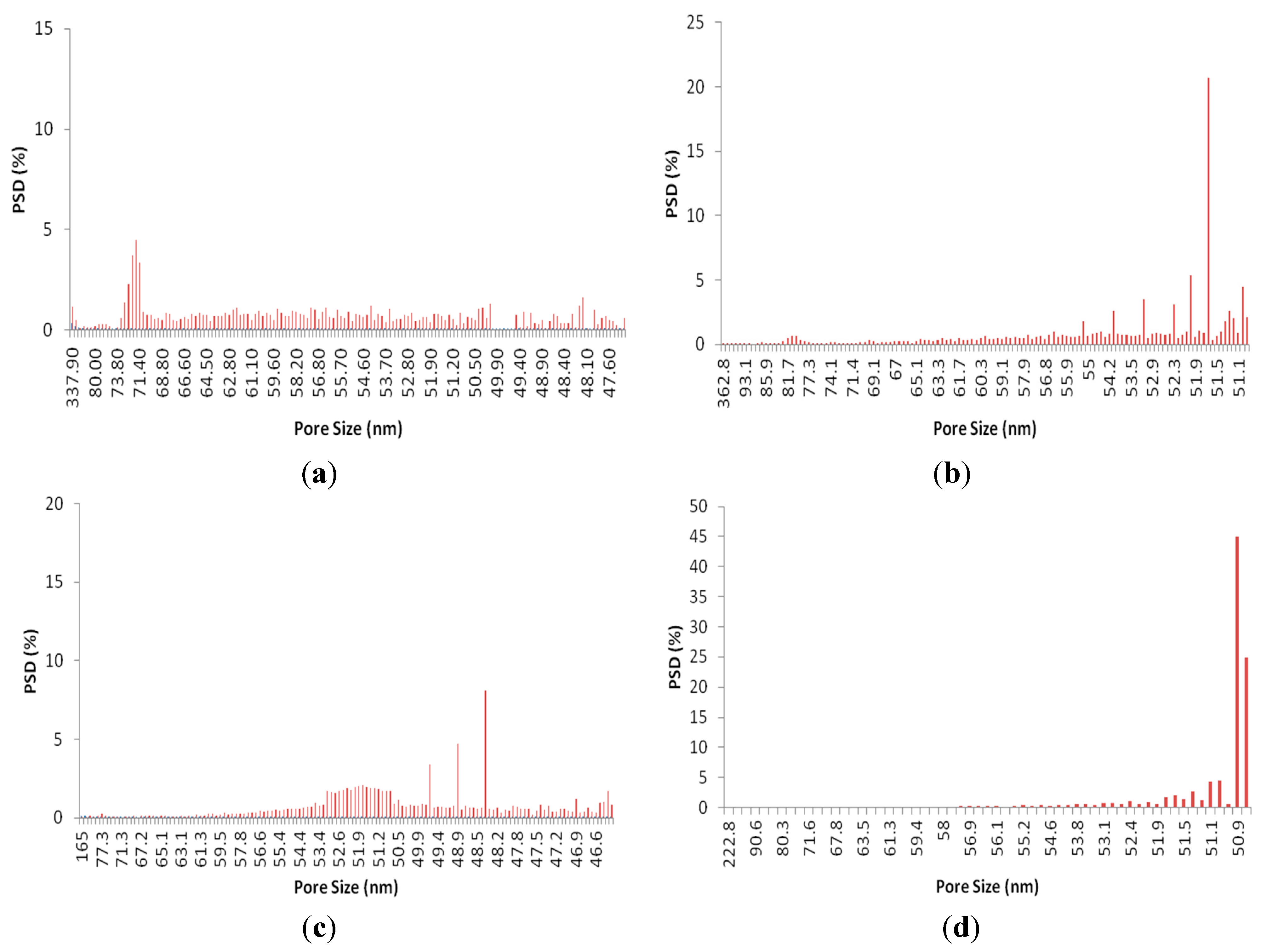
5.2. Pore size and distribution measurement

To observe pores of membranes, a capillary flow porometer (CFP) is operated as much as scanning electron microscopy (SEM) [21,22,23]. Table 2 described statistical values of average pore size of membranes. The reason that pore size distribution was measured by operating CFP is because accurate pore size distribution is not available to be measured by SEM on account of different coating thickness of membranes [24,25]. As the graft copolymer was added into the casting solution, the mean pore size was reduced. As shown in Figure 5, the pore size distribution range of A-1 and B-1 membranes were broadly dispersed. In contrast, the pore size distribution range of A-2 and B-2 membranes was narrow. Figure 5 indicated A-2 and B-2 membranes had more uniform pore size in comparison to A-1 and B-1 membranes. In particular, B-2 containing PVDF-g-PHEA showed the highest peak of PSD (i.e., about 45%) at 50.9 nm, whereas B-1 without additive indicated value less than approximately 10% at 48.3 nm. According to [17], PVDF membranes containing PVDF-g-PSPMA had more uniform pore size than pristine PVDF membrane. It was confirmed that the hydrophilic copolymer contributed to more uniform pore size. In conclusion, A2 and B2 membranes included the hydrophilic property unlike A1 and B1 membranes.
Table 2. Contact angle values of membranes.
MembraneA-1A-2B-1B-2
Contact Angle68.6°64.368.0°61.8°
Mean pore size (nm)60.660.553.453.2
Figure 5. Pore Size Distribution of (a) A-1; (b) A-2; (c) B-1 and (d) B-2 membranes.
Applsci 05 01992 g005

5.3. Morphology Analysis

Figure 6 and Figure 7 display SEM images of surface and cross section of pristine membranes and PVDF-g-PHEA included PVDF membranes. Morphology analysis is important to analyze the structure of membranes in detail. Surface and cross section of membranes were magnified at 50,000 and 1000 times, respectively. As shown in Figure 6 and Figure 7, numerous pores were observed in the surface of all membranes including PVDF pristine membranes and PVDF membranes containing PVDF-g-PHEA. When comparing PVDF membranes containing PVDF-g-PHEA with PVDF pristine membranes to observe the cross-sectional image as shown in Figure 6 and Figure 7, the blending of 0.9% PVDF-g-PHEA additive (B-2) led to formation of membrane cross section with deep and macrovoid holes in comparison with no additive (B-1). 0.6% PVDF-g-PHEA (A-2) caused macrovoid holes in the lower side in comparison with 9.5% PVDF pristine membrane (A-1). As observed in the top layer of the membrane, PVDF membrane blended with 0.9% PVDF-g-PHEA additive absolutely possessed thinner top layer than 10% PVDF pristine membrane. This phenomenon was observed when hydrophilic material, PVDF-g-PHEA additive, was combined with PVDF to fabricate membranes. It may be attributed to instantaneous demixing process in water bath during phase inversion due to hydrophilic PVDF-g-PHEA in PVDF casting solution. There are numerous relative papers such as [2,26]. According to the SEM images of surface of membranes and cross section of membranes, as the concentration of PVDF-g-PHEA was increased, macrovoid holes were observed in the lower side and top layer of the membrane became thinner.
Figure 6. SEM images: surface of (a) A-1; (b) A-2; (c) B-1, and (d) B-2 membranes.
Applsci 05 01992 g006
Figure 7. SEM images: cross-section of (a) A-1; (b) A-2; (c) B-1 and (d) B-2 membranes.
Applsci 05 01992 g007
Figure 8 and Figure 9 indicate permeate flux of all membranes during filtration of 6 and 20 ppm HA solution. To demonstrate comparable difference in permeate flux, the pore size of membranes was made similarly, respectively [17]. Generally, the PVDF membranes blended with PVDF-g-PHEA (A-2 and B-2) had faster final permeate flux (J) than PVDF pristine membranes (i.e., A-1 and B-1). The reason that the initial fluxes (J0) of A-2 and B-2 were slower than those of A-1 and B-1 is because pore size of PVDF membranes blended with PVDF-g-PHEA was smaller than that of PVDF pristine membranes as shown in Table 2. In other words, A-1 and B-1, with larger pore size than the A-2 and B-2, showed higher initial permeate flux according to Hagen-Poiseuille equation (see Table 2). Hargen-Poiseuille equation represents that permeate flux is proportional to 4 times the pore size [17]. However, despite the A-2 and B-2 membrane having lower initial flux and smaller pore size, reversal phenomenon was observed in permeate flux as time passed. After constant time passed, the final fluxes of A-2 and B-2 were higher than those of A-1 and B-1. To be specific, even though initial fluxes for A-1, A-2, B-1, and B-2 membranes were 312.08, 310.15, 287.30, and 286.01 LMH at 6 ppm HA solution, the final fluxes for A-1, B-1, A-2 and B-2 were 131.45, 137.18, 133.61, and 144.98 LMH at 6 ppm HA solution after 240 min, respectively. That is, the difference of the final fluxes between PVDF membranes blended with PVDF-g-PHEA and PVDF pristine membranes were 5.73 and 11.37 LMH at 6 ppm HA solution, respectively. In addition, initial fluxes of A-1, A-2, B-1, and B-2 membranes were 289.43, 279.95, 264.53, and 260.92 LMH at 20 ppm HA solution, respectively. At 240 min, the final fluxes of A-1, B-1, A-2 and B-2 were 104.92, 111.48, 105.42 and 116.99 LMH at 20 ppm HA solution, respectively. This means that the difference of the final fluxes between PVDF membranes blended with PVDF-g-PHEA and PVDF pristine membranes were 5.73 and 11.37 LMH at 6 ppm HA solution, respectively. Additionally, the difference of the final fluxes between PVDF membranes blended with PVDF-g-PHEA and PVDF pristine membranes were 6.56 and 11.57 LMH at 20 ppm HA solution, respectively. As a result of the permeate flux performance, the concentration of PVDF-g-PHEA were increased, the difference of the final flux became larger at 20 ppm HA solution than at 6 ppm HA solution. The more the concentration of HA solution was added, the lower the final permeate flux was.
Figure 8. Permeate flux of membranes during filtration of 6 ppm HA solution at 1 bar.
Applsci 05 01992 g008
Figure 9. Permeate flux of membranes during filtration of 20 ppm HA solution at 1 bar.
Applsci 05 01992 g009
Flux test was performed in order to demonstrate improvement of permeate flux during ultrafiltration. However, some researchers may believe that permeate fluxes are not accurate due to different initial flux. For that reason, authors conducted the normalized flux (J/J0) test to confirm more reliable flux difference originated from different initial HA flux. Normalized flux measurement is an important method to evaluate performance of membranes without reference to the pore size. Normalized flux of humic acid (6 and 20 ppm) was evaluated by this equation:
Normalized flux = J/J0
where J was the final flux of the humic acid permeated and J0 was the initial flux of the humic acid permeated.
Figure 10 and Figure 11 show normalized fluxes of membranes. As normalized fluxes were calculated, normalized flux values of A-1 and B-1 were 0.42 and 0.47, and normalized flux values of A-2 and B-2 were 0.44 and 0.51 at 6 ppm HA solution, respectively. When normalized fluxes were evaluated at 20 ppm HA solution, normalized flux values of A-1 and B-1 were 0.36 and 0.40, and normalized flux values of A-2 and B-2 were 0.40 and 0.45, respectively. The differences of normalized fluxes between PVDF membranes blended with PVDF-g-PHEA and PVDF pristine membranes were 0.02 and 0.04 at 6 ppm HA solution. Additionally, the differences of the normalized flux values between PVDF membranes blended with PVDF-g-PHEA and PVDF pristine membranes were 0.04 and 0.05 at 20 ppm HA solution, respectively. As a result of the normalized flux calculation, when the concentration of PVDF-g-PHEA was increased, the difference of the final flux became larger. Permeate flux performance and normalized flux calculation indicated the high concentration of PVDF-g-PHEA improved the permeate flux of PVDF membranes.
Figure 12 represents rejection data of membranes during filtration of 6 ppm and 20 ppm humic acid solution. The initial rejections of A-1, A-2, B-1 and B-2 membranes were 71.7%, 73.0%, 79.3%, and 83.8% at 6 ppm humic acid solution, respectively. Rejection percents of A-1, A-2, B-1, and B-2 membranes were increased as time was passed. The final rejections of A-1, A-2, B-1, and B-2 membranes were 82.7%, 83.8%, 87.8%, and 88.8% at 6 ppm humic acid solution, respectively. The initial rejections of A-1, A-2, B-1, and B-2 membranes were 83.7%, 81.3%, 91.1%, and 90.9%, respectively. As time passed, rejection percentages of A-1, A-2, B-1, and B-2 membranes were increased and reversal phenomenon was occurred. After two hours, the final rejections of A-1, A-2, B-1, and B-2 membranes were 89.8%, 90.1%, 92.9%, and 93.4%. Based on pore size distribution, Figure 5, the reason that rejection of A-2 and B-2 membranes was higher than A-1 and B-1 membranes was because average pore size of A-2 and B-2 membranes was smaller than that of A-1 and B-1 membranes. Additionally, humic acid passed through larger pores easier. Therefore, the humic acid rejection percent of A-1 and B-1 membranes was lower than that of A-2 and B-2 membranes. More humic acid was stacked on the surface of A-1 and B-1 membranes and it caused membrane fouling [18].
Figure 10. Normalized flux of membranes during filtration of 6 ppm HA solution at 1 bar.
Applsci 05 01992 g010
Figure 11. Normalized flux of membranes during filtration of 20 ppm HA solution at 1 bar.
Applsci 05 01992 g011
Figure 12. Rejection % of membranes at 6 ppm (a) and 20 ppm (b) humic acid.
Applsci 05 01992 g012

6. Conclusions

In summary, synthesis of PVDF-g-PHEA graft copolymer is confirmed using FT-IR and NMR data. More specifically, hydroxyl and ketone groups of PVDF-g-PHEA graft copolymer, as well as three peaks connected to PHEA at 4.2, 3.5 and 3.3 ppm, are observed using FT-IR and NMR, respectively. As an evaluation result, the grafting ratio of PHEA in PVDF-g-PHEA was 22.6% in a mass basis. TGA data for PVDF-g-PHEA indicates that PVDF was successfully polymerized with 2-hydroxyethyl acrylate. Contact angle is one of the important and brief criteria to recognize the hydrophilicity of the membrane. As a result of measurement, contact angles of 9.5% and 10% PVDF pristine membranes were 68.6° and 68.0°, respectively. Contact angles of PVDF membranes blended with 0.6% and 0.9% PVDF-g-PHEA were 64.3° and 61.8°, respectively. In conclusion, the contact angle was decreased by blending of PVDF-g-PHEA additive in PVDF casting solution. Moreover, macrovoid holes are discovered in cross sectional SEM images of PVDF UF membrane containing PVDF-g-PHEA. The final humic acid rejection percent of PVDF membranes blended with PVDF-g-PHEA additive was higher than that of PVDF pristine membranes at 6 ppm and 20 ppm. Average pore size of membranes was the key factor to influence the humic acid rejection percent. Finally, permeate flux indicates increase by blending of PVDF-g-PHEA additive, which has hydrophilic characteristics. Based on above characterizations, it suggests that PVDF-g-PHEA graft copolymer is successfully synthesized, thereby resulting in the formation of hydrophilic PVDF UF membrane. Also, this indicates the possibility of using PVDF-g-PHEA to fabricate membranes with improved flux during water treatment containing humic acid.

Acknowledgments

This work was supported by the Human Resources Program in Energy Technology of the Korea Institute of Energy Technology Evaluation and Planning (KETEP), granted financial resource from the Ministry of Trade, Industry & Energy, Republic of Korea (No. 20154010200810).

Author Contributions

Kwang-Mo Kim and Sahng Hyuck Woo contributed equally to this work in order to conduct the experiments, fabricate the membranes, write first draft and complete the article; Ju Sung Lee and Hyun Sic Park reviewed the data; Jinwon Park and Byoung Ryul Min advised to complete this article.

Conflicts of Interest

The authors declare no conflict of interest.

References

  1. Mehrparvar, A.; Rahimpour, A.; Jahanshahi, M. Modified ultrafiltration membranes for humic acid removal. J. Taiwan Inst. Chem. Eng. 2014, 45, 275–282. [Google Scholar] [CrossRef]
  2. Liu, B.; Chen, C.; Zhang, W.; Crittenden, J.; Chen, Y. Low-cost antifouling PVC ultrafiltration membrane fabrication with Pluronic F 127: Effect of additives on properties and performance. Desalination 2012, 307, 26–33. [Google Scholar] [CrossRef]
  3. Woo, S.H.; Park, J.; Min, B. Relationship between permeate flux and surface roughness of membranes with similar water conract angle values. Sep. Purif. Technol. 2015, 146, 187–191. [Google Scholar] [CrossRef]
  4. Yan, L.; Wang, J. Development of a new polymer membrane—PVB/PVDF blended membrane. Desalination 2011, 281, 455–461. [Google Scholar] [CrossRef]
  5. Yang, X.; Zhang, B.; Liu, Z.; Deng, B.; Yu, M.; Li, L.; Jiang, H.; Li, J. Preparation of the antifouling microfiltration membranes from poly(N,N-dimethylacrylamide) grafted poly(vinylidene fluoride) (PVDF) powder. J. Mater. Chem. 2011, 21, 11908–11915. [Google Scholar] [CrossRef]
  6. Meng, J.; Chen, C.; Huang, L.; Du, Q.; Zhang, Y. Surface modification of PVDF membrane via AGET ATRP directly from the membrane surface. Appl. Surf. Sci. 2011, 257, 6282–6290. [Google Scholar] [CrossRef]
  7. Hashim, N.A.; Liu, F.; Li, K. A simplified method for preraration of hydrophilic PVDF membranes from an amphiphilic graft copolymer. J. Membr. Sci. 2009, 345, 134–141. [Google Scholar] [CrossRef]
  8. Abed, M.R.M.; Kumbharkar, S.C.; Groth, A.M.; Li, K. Economical production of PVDF-g-POEM for use as a blend in preparation of PVDF based hydrophilic hollow fibre membranes. Sep. Purif. Technol. 2013, 106, 47–55. [Google Scholar] [CrossRef]
  9. Woo, S.H.; Kim, K.; Park, J.; Min, B. Preparation and Characterization of Poly(vinylidene fluoride) (PVDF) Membrane. Chem. Lett. 2015, 44, 85–87. [Google Scholar] [CrossRef]
  10. Sui, Y.; Wang, Z.; Gao, X.; Gao, C. Antifouling PVDF ultrafiltration membranes incorporating PVDF-g-PHEMA additive via atom transfer radical graft polymerizations. J. Membr. Sci. 2012, 413–414, 38–47. [Google Scholar] [CrossRef]
  11. Hashim, N.A.; Liu, F.; Abed, M.R.M.; Li, K. Chemistry in spinning solutions: Surface modification of PVDF membranes during phase inversion. J. Membr. Sci. 2012, 415–416, 399–411. [Google Scholar] [CrossRef]
  12. Chen, Y.; Liu, D.; Deng, Q.; He, X.; Wang, X. Atom Transfer Radical Polymerization Directly from Poly(vinylidene fluoride): Surface and Antifouling Properties. J. Polym. Sci. A Polym. Chem. 2006, 44, 3434–3443. [Google Scholar] [CrossRef]
  13. Wang, W.; Chen, L. “Smart” Membrane Materials: Preparation and Characterization of PVDF-g-PNIPAAm Graft Copolymer. J. Appl. Polym. Sci. 2007, 104, 1482–1486. [Google Scholar] [CrossRef]
  14. Liu, B.; Chen, C.; Li, T.; Crittenden, C.; Chen, Y. High performance ultrafiltration membrane composed of PVDF blended with its derivative copolymer PVDF-g-PEGMA. J. Membr. Sci. 2013, 445, 66–75. [Google Scholar] [CrossRef]
  15. Akthakul, A.; Salinaro, R.F.; Mayes, A.M. Antifouling Polymer Membranes with Subnanometer Size Selectivity. Macromolucules 2004, 37, 7663–7668. [Google Scholar] [CrossRef]
  16. Guillen, G.R.; Pan, Y.; Li, M.; Hoek, E.M. Precipitation and characterization of membranes formed by nonsolvent induced phase separation: A review. Ind. Eng. Chem. Res. 2011, 50, 3798–3817. [Google Scholar] [CrossRef]
  17. Woo, S.H.; Lee, J.S.; Lee, H.H.; Park, J.; Min, B. Preparation method of crack-free PVDF microfiltration membrane with enhanced antifouling characteristics. Appl. Mater. Interfaces 2015, 7, 16466–16477. [Google Scholar] [CrossRef] [PubMed]
  18. Fu, X.; Maruyama, T.; Sotani, T.; Matsuyama, H. Effect of surface morphology on membrane fouling by humic acid with the use of cellulose acetate butyrate hollow fiber membranes. J. Membr. Sci. 2008, 320, 483–491. [Google Scholar] [CrossRef]
  19. Kim, Y.W.; Park, J.T.; Koh, J.H.; Roh, D.K.; Kim, J.H. Anhydrous proton conducting membranes based on crosslinked graft copolymer electrolytes. J. Membr. Sci. 2008, 325, 319–325. [Google Scholar] [CrossRef]
  20. Kim, Y.W.; Lee, D.K.; Lee, K.J.; Kim, J.H. Single-step synthesis of proton conducting poly(vinylidene fluoride) (PVDF) graft copolymer electrolytes. Eur. Polym. J. 2008, 44, 932–939. [Google Scholar] [CrossRef]
  21. Jena, A.; Gupta, K. Characterization of pore structure of filtration media. Fluid Part. Sep. J. 2002, 14, 227–241. [Google Scholar]
  22. Li, D.; Frey, M.W.; Joo, Y.L. Characterization of nanofibrous membranes with capillary flow porometry. J. Membr. Sci. 2006, 286, 104–114. [Google Scholar] [CrossRef]
  23. Liao, Y.; Wang, R.; Tian, M.; Qiu, C.; Fane, A.G. Fabrication of polyvinylidene fluoride (PVDF) nanofiber membranes by electro-spinning for direct contact membrane distillation. J. Membr. Sci. 2013, 425, 30–39. [Google Scholar] [CrossRef]
  24. Lee, N.; Amy, G.; Croué, J.-P.; Buisson, H. Morphological analyses of natural organic matter (NOM) fouling of low-pressure membranes (MF/UF). J. Membr. Sci. 2005, 261, 7–16. [Google Scholar] [CrossRef]
  25. Kim, J.Y.; Lee, H.K.; Kim, S.C. Surface structure and phase separation mechanism of polysulfone membranes by atomic force microscopy. J. Membr. Sci. 1999, 163, 159–166. [Google Scholar] [CrossRef]
  26. Tao, M.; Liu, F.; Xue, L. Hydrophilic poly(vinylidene fluoride) (PVDF) membrane by in situ polymerisation of 2-hydroxyethyl methacrylate (HEMA) and micro-phase separation. J. Mater. Chem. 2012, 22, 9131–9137. [Google Scholar] [CrossRef]

