Article

Cyclic Crack Monitoring of a Reinforced Concrete Column under Simulated Pseudo-Dynamic Loading Using Piezoceramic-Based Smart Aggregates

1
Department of Mechanical Engineering, University of Houston, 4800 Calhoun RD, Houston, TX 77204, USA
2
Energo Engineering (A KBR Company), 1300 W Sam Houston Parkway South, Suite 100, Houston, TX 77042, USA
3
School of Engineering and Applied Science, George Washington University, Science & Engineering Hall, 800 22nd Street, NW, Washington, DC 20052, USA
4
Department of Civil and Environmental Engineering, University of Houston, 4800 Calhoun RD, Houston, TX 77204, USA
*
Author to whom correspondence should be addressed.
Appl. Sci. 2016, 6(11), 341; https://doi.org/10.3390/app6110341
Submission received: 21 September 2016 / Revised: 2 November 2016 / Accepted: 2 November 2016 / Published: 8 November 2016
(This article belongs to the Special Issue Structural Health Monitoring (SHM) of Civil Structures)

Abstract

:
Structural health monitoring is an important aspect of maintenance for bridge columns in areas of high seismic activity. In this project, recently developed piezoceramic-based transducers, known as smart aggregates (SA), were utilized to perform structural health monitoring of a reinforced concrete (RC) bridge column subjected to pseudo-dynamic loading. The SA-based approach has been previously verified for static and dynamic loading but never for pseudo-dynamic loading. Based on the developed SAs, an active-sensing approach was developed to perform real-time health status evaluation of the RC column during the loading procedure. The existence of cracks attenuated the stress wave transmission energy during the loading procedure and reduced the amplitudes of the signal received by SA sensors. To detect the crack evolution and evaluate the damage severity, a wavelet packet-based structural damage index was developed. Experimental results verified the effectiveness of the SAs in structural health monitoring of the RC column under pseudo-dynamic loading. In addition to monitoring the general severity of the damage, the local structural damage indices show potential to report the cyclic crack open-close phenomenon subjected to the pseudo-dynamic loading.

1. Introduction

Reinforced concrete (RC) is the most common material used in infrastructure such as bridges [1,2]. RC columns are often the primary elements of energy dissipation in bridges subjected to seismic loads. Failure of bridge columns can cause the collapse of bridge girders, which has been the catastrophic scenario for the majority of bridges damaged in past earthquakes. After a seismic event, it is imperative to quickly assess the health condition of an RC structure to provide early warning of the structural damage. It is essential to design a structural health monitoring system that can monitor and report the health status for large-scale infrastructures in real-time.
With attractive features of low-cost, small size, large bandwidth, and actuating-sensing functions, piezoceramics have been increasingly employed in many engineering fields [3,4,5,6,7]. In this project, piezoceramic-based devices, called smart aggregates (SA), were utilized as transducers for structural health monitoring of RC columns under a pseudo-dynamic loading procedure. In addition to the structural health monitoring function, the smart aggregate can be used to perform early-age concrete strength monitoring [8,9], impact detection [10], seismic detection [11], and soil freeze-thaw monitoring [12], demonstrating that SAs are multi-functional devices. In previous studies, SAs have been successfully implemented for structural health monitoring of various concrete structures under different loading cases including: a concrete bridge bent-cap under static loading [13], a concrete frame under static loading [14,15], a shear wall under reversed cyclic loading [16], columns under seismic loading [17], stress wave base communication in concrete structures [18,19] and columns under reversed cyclic loading [20,21]. The purpose of this project was to further verify the effectiveness of the smart aggregate in health monitoring of a RC concrete column tested with pseudo-dynamic loads.
To verify the effectiveness of the proposed smart aggregate under pseudo-dynamic loads, the smart aggregates were used as transducers to perform health monitoring on RC columns under a mathematically simulated earthquake record. One full-scale circular RC column was designed at George Washington University based on an American Association of State Highway and Transportation Officials (AASHTO) design example for a curved bridge. The column was tested at the Newmark Structural Engineering Laboratory at the University of Illinois, Urbana-Champaign. The employed smart aggregates were embedded at pre-determined locations in the full-scale RC column to perform structural health monitoring. During the test, the column was assumed to be the pier in the same curved bridge and subjected to a simulated earthquake record, one step at a time. After each step, the stiffness of the column was calculated and the next step of the earthquake record was adjusted to account for any decrease in stiffness. Structural health monitoring was performed periodically during the approximately 40-h test. Due to the pseudo-dynamic loading, the investigated RC column was subject to crack. When the column was pushed on one side, cracks opened; when the column was pulled back, the cracks closed. In the active-sensing approach, one smart aggregate was used as an actuator to generate a repeated swept sine signal while the others were used as sensors to detect the signal response. The existence of cracks, acting as stress relief, attenuated the wave propagation, so the signal received by SA sensors correspondingly decreased. A structural damage index was formed based on the wavelet packet-based tools. The general increasing values of the developed structural damage indices for each implemented SA successfully detect the damage severity during the test. In addition, the cyclic behavior of the local damage indices successfully monitored the crack opening and closing phenomenon subject to the pseudo-dynamic loading.

2. Principles

2.1. Literature Review

Recently, structural health monitoring of large-scale structures is highly in demand in order to reduce maintenance cost and enhance structural safety. Traditional methods, such as X-ray or ultrasonic C-scan technologies, are expensive and inefficient for monitoring the structural health of large-scale structures. Fiber optical sensors, including the Fiber Bragg Grating (FBG) sensors, are also being used for monitoring the health condition of various concrete structures [22,23,24]. However, fiber optical sensors offer only local measurements, greatly limiting their applications. Piezoelectric transducers have emerged as a new tool in the monitoring of large-scale structures due to their advantages including low-cost, small size, large bandwidth, and actuating-sensing functions. Currently, two popular methods of the piezoelectric-based health monitoring approaches have been reported to monitor the concrete structures using piezoelectric-based approach: the impedance-based method and the vibration-characteristic method.
The impedance-based health monitoring approach is capable of monitoring the local damage of structures [25,26,27,28]. The principle of this approach is based on the electromechanical coupling effect of piezoelectric materials in relative high frequency range. The impedance-based approach has been applied to RC beams [29,30], frames [31], shear walls [15], and composite RC/masonry walls [32], in addition to RC bridges [33]. Meanwhile, a numerical modeling study on impedance-based damage identification has also been conducted [34]. Recently, a new real-time integrated wireless structural health monitoring (SHM) system named “WiAMS” was developed to detect the structural damage based on the impedance signature using embedded and surface-bonded lead zirconate titanate (PZT) transducers [35,36]. Since the impedance-based method is sensitive to the local damage where PZT sensors are placed [37], a combination of smart aggregates with surface bonded PZTs was studied to assess both the local and overall conditions of the structure [38].
In contrast, the vibration-characteristic approach utilizes piezoelectric actuators to generate waves that propagate within the structure, and compares the structural vibration-characteristic parameters, such as the modal shape and frequency [39], active-sensing approach [40], or transfer functions [41], with those of the healthy state to detect damage. Delamination between reinforcing bars and concrete has also been studied using this approach [42,43]. In this approach, the excitation frequency range is normally from several hundred hertz to several kilohertz. However, the operating frequency of this approach is much lower than impedance-based approach.

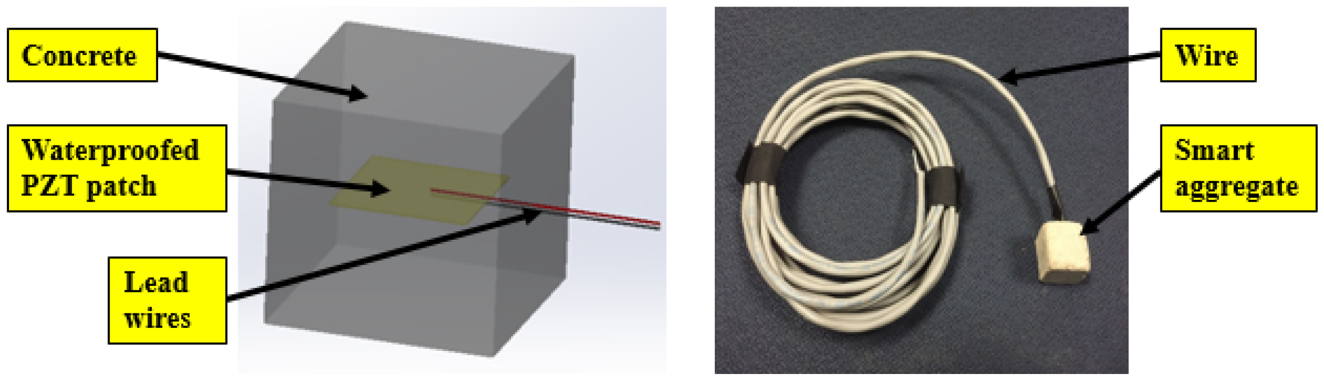
2.2. Smart Aggregate-Based Structural Health Monitoring System

Piezoelectric materials, exhibiting piezoelectricity that can convert mechanical strain to electrical signals and vice versa, have been widely used as ultrasonic transmitters and receivers in many applications. Lead Zirconate Titanate (PZT) is one of the most popular materials among piezoelectric materials. Since PZT material is fragile and easily damaged, a smart aggregate (SA) was designed by embedding a waterproofed PZT patch with lead wires into a concrete block [39]. The schematic structure and a photo of smart aggregate are shown in Figure 1. The detailed parameters of the rectangular PZT patch is provided in Table 1. Due to the stable physical properties of concrete, the designed SAs are capable of acting as embedded transducers to perform the structural health monitoring in real-time. When SAs are installed in the reinforcing cage before concrete casting, we used wires to especially fix the SAs with the reinforcing cage. Just like an aggregate in concrete, our smart aggregate will be surrounded by the liquid cement. Both a chemical and physical bond will form between the cement and the SA during the curing process and therefore good bonding is ensured.
Figure 2 gives an example to illustrate the smart aggregate-based active sensing approach for multi-crack detection in a concrete column. As shown in Figure 2, one smart aggregate functions as an actuator to generate guided waves propagating in the concrete structure. Other distributed smart aggregates are used as sensors to detect the wave responses. If a crack appears in the structure, it acts as a stress relief in the wave propagation path. Therefore, the energy of the received signal from corresponding SA sensors will attenuate.
Note that the energy attenuation ratio is highly dependent on the severity of the cracks. In order to detect the crack severity, a wavelet packet-based structural damage index was developed in this paper. In the wavelet decomposition process, a sensor signal X can be decomposed with n-level wavelet packets into 2n signal sets {X1, X2, , X2n} [44]. Xj is the decomposed sensor signal and j is the frequency band (j = 1 2n). Xj can be expressed in Equation (1).
Xj = [Xj,1, Xj,2, , Xj,m]
where m is the number of sampling data. Additionally, the energy of the decomposed signal Ej is defined by Equation (2):
Ej = Xj,12 + Xj,22 +···Xj,m2
According to the data measured at time i, the signal energy vector at time i is given by Equation (3):
Ei,j = [Ei,1, Ei,2, …, Ei,2n]
Therefore, by using root-mean-square deviation (RMSD), a wavelet packet-based structural damage index I is given by Equation (4) [39]:
I = j = 1 2 n ( E i , j E 1 , j ) 2 / j = 1 2 n E 1 , j 2
where E 1 , j is considered as the health status of the structure. From the structural damage index, it can be found that when the values of subsequent energy vectors are close to E 1 , j , corresponding to minor or no change of the structure, the value of the structural damage index approaches 0. In contrast, when the values of subsequent energy vectors approach 0, corresponding to serious structure damage, the value of the structural damage index approaches 1. It can be seen that the values of the structural damage index between 0 and 1 can be utilized to determine the damage severity of the structure, such as the crack condition discussed in this paper. However, to quantitatively determine the actual crack size or image using the current developed damage index is still not feasible.

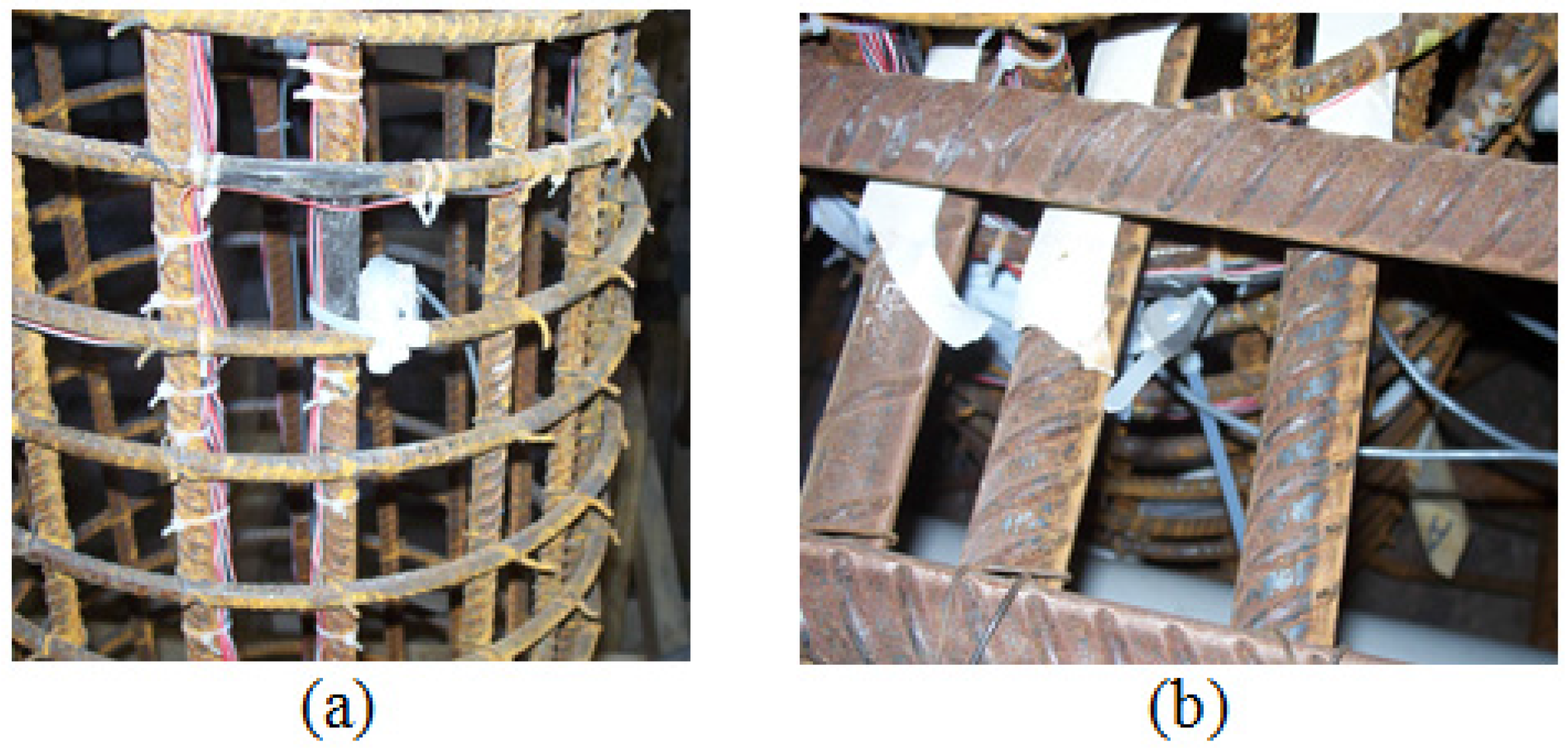
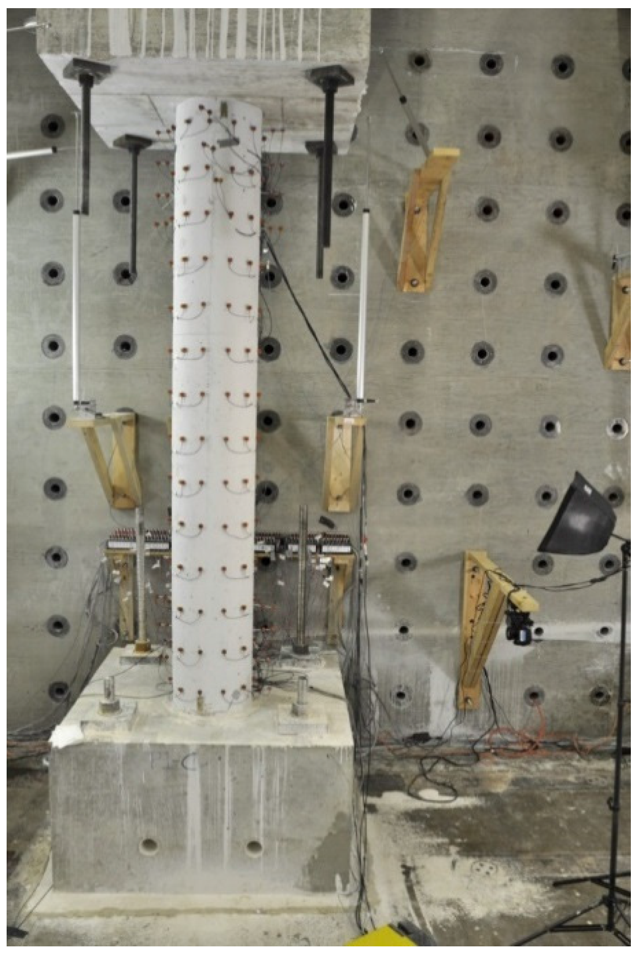
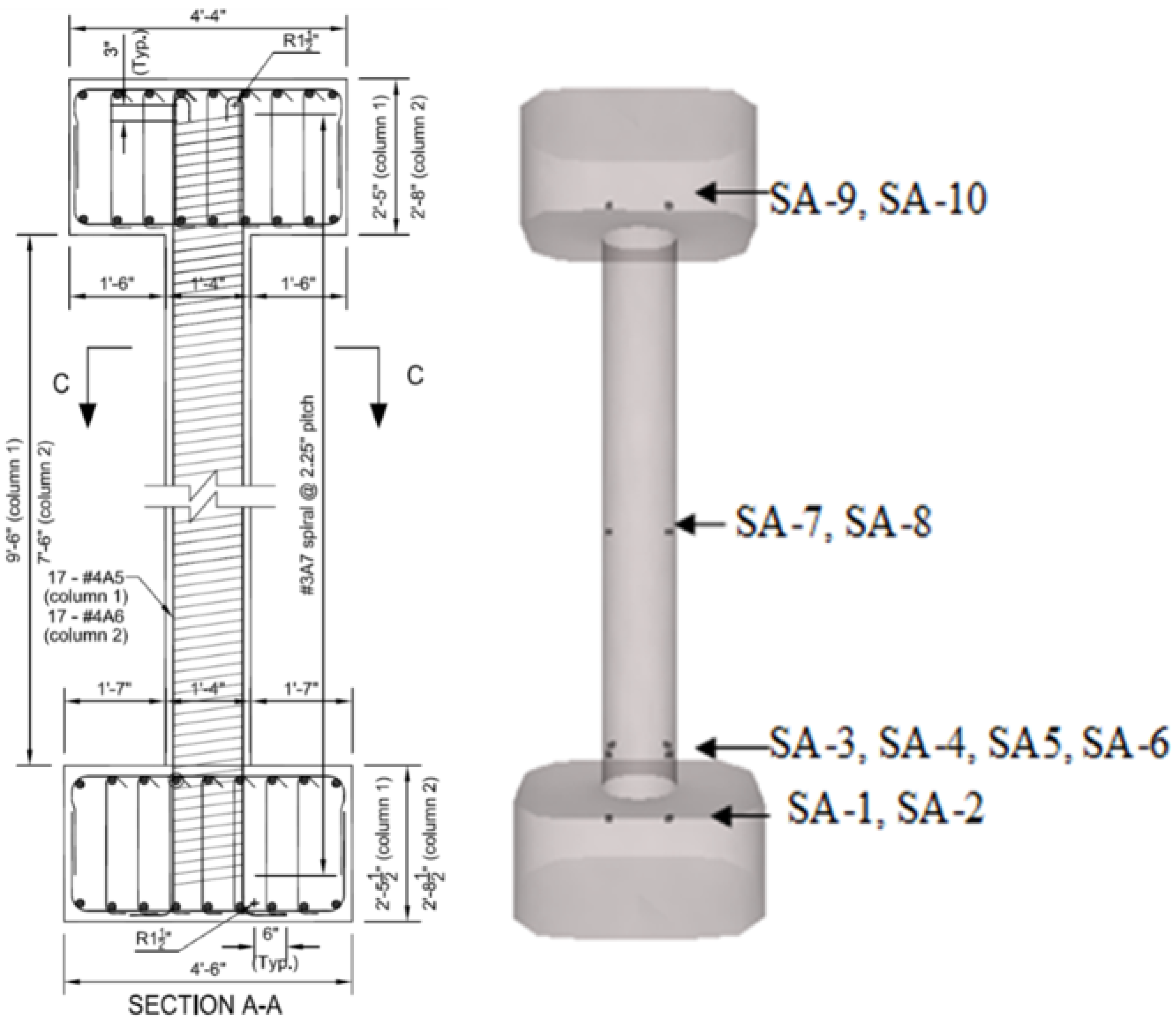
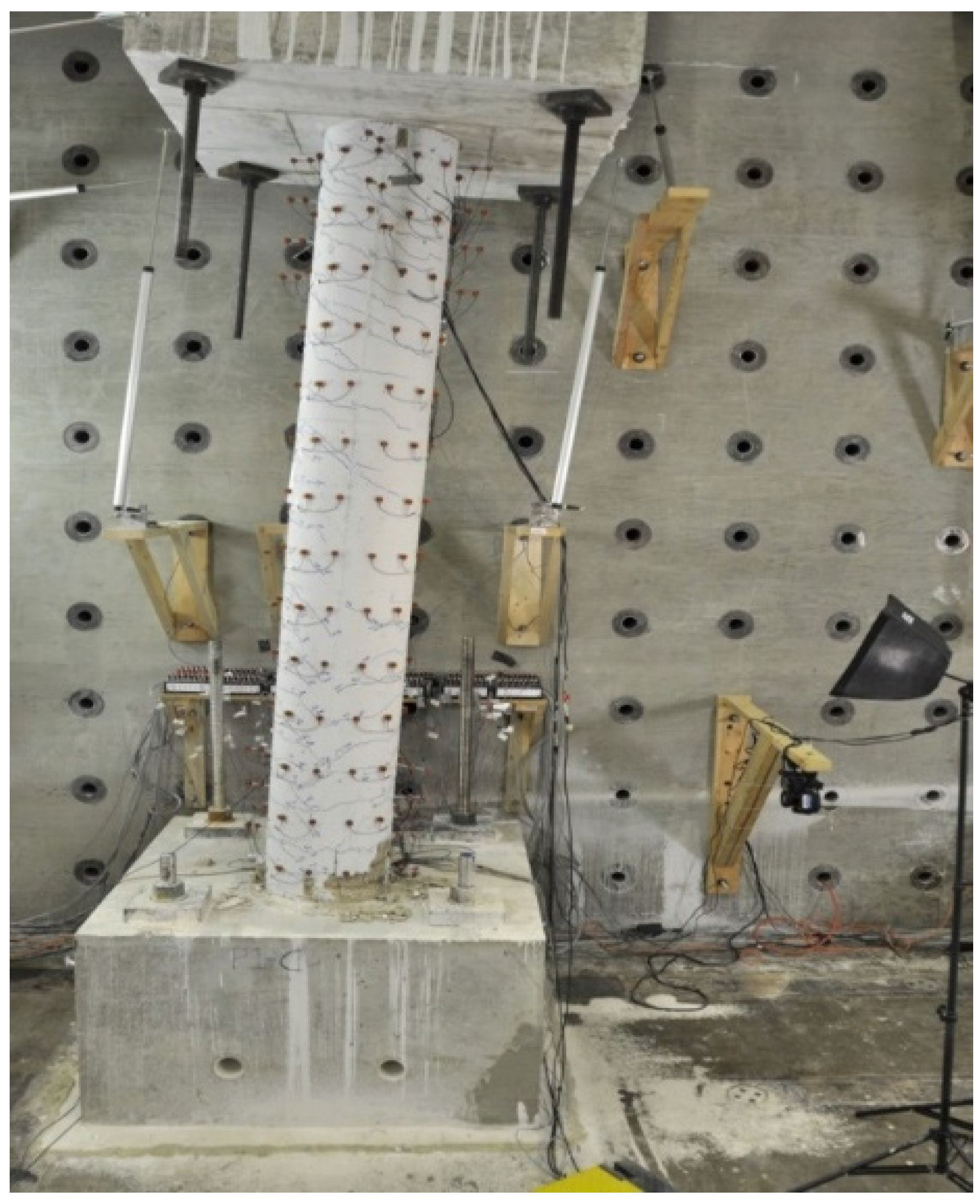
3. Experimental Setup

An RC column instrumented with 10 smart aggregates was fabricated at Prestressed Engineering Company, LLC in Blackstone, IL, USA. The location of smart aggregates in the concrete column is shown in a structural drawing and a three-dimensional view, as shown in Figure 3. Figure 4 shows pictures of some smarts aggregates installed in the rebar cage of the column.
A series of 330 kip actuators called “Load and Boundary Condition Boxes” (LBCDs) were placed at the top of the full-scale column to apply load to the specimen. The test concrete column was mounted to a strong floor using all-thread rods. The column was instrumented with linear variable differential transformer (LVDTs), strain gauges mounted on the reinforcing steel, Krypton displacement cameras (Metris Design, Leuven, Belgium), in addition to the smart aggregates. A photo of the casted concrete column can be seen in Figure 5. Using the smart aggregate designation shown in Figure 3, SA-1 was used as the actuator to generate repeated swept sine wave through a function generator. The amplitude, period, and the frequency range of the swept sine wave are 10 V, 3 s, and 100 Hz–10 kHz, respectively. SA-3 through SA-10 were used as sensors to detect the signal. The sensing signal was recorded by a NI-6353 data acquisition system. The sampling frequency of the data acquisition system is 100 kS/s per channel.

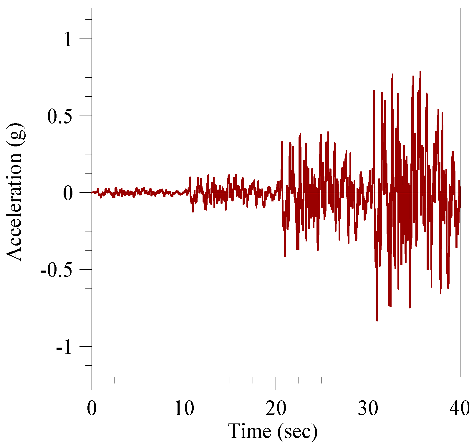
4. Loading Protocols

During the test, the concrete column was assumed to be a column in a curved bridge subjected to a simulated pseudo-dynamic earthquake record. After each step of the record, the stiffness of the column was calculated and the next step of the earthquake record was adjusted using a finite element analysis to account for any decrease in stiffness in the system. The simulated earthquake record represented a 40 s earthquake. The magnitude of the acceleration was increased every 10 s. Figure 6 shows the acceleration record used in this loading test. Structural health monitoring tests were performed periodically during the approximately 40-h test.

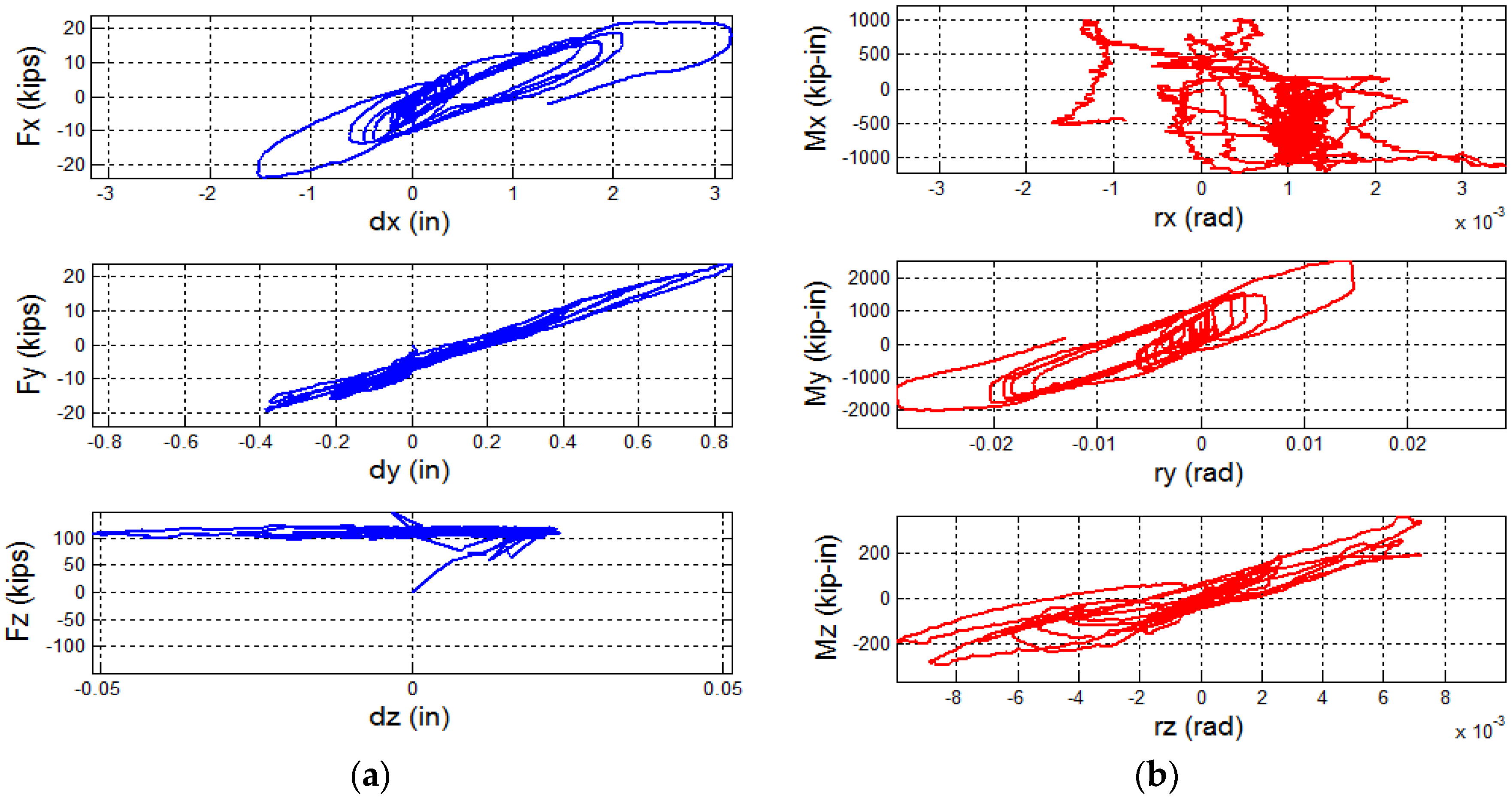
5. Experimental Results

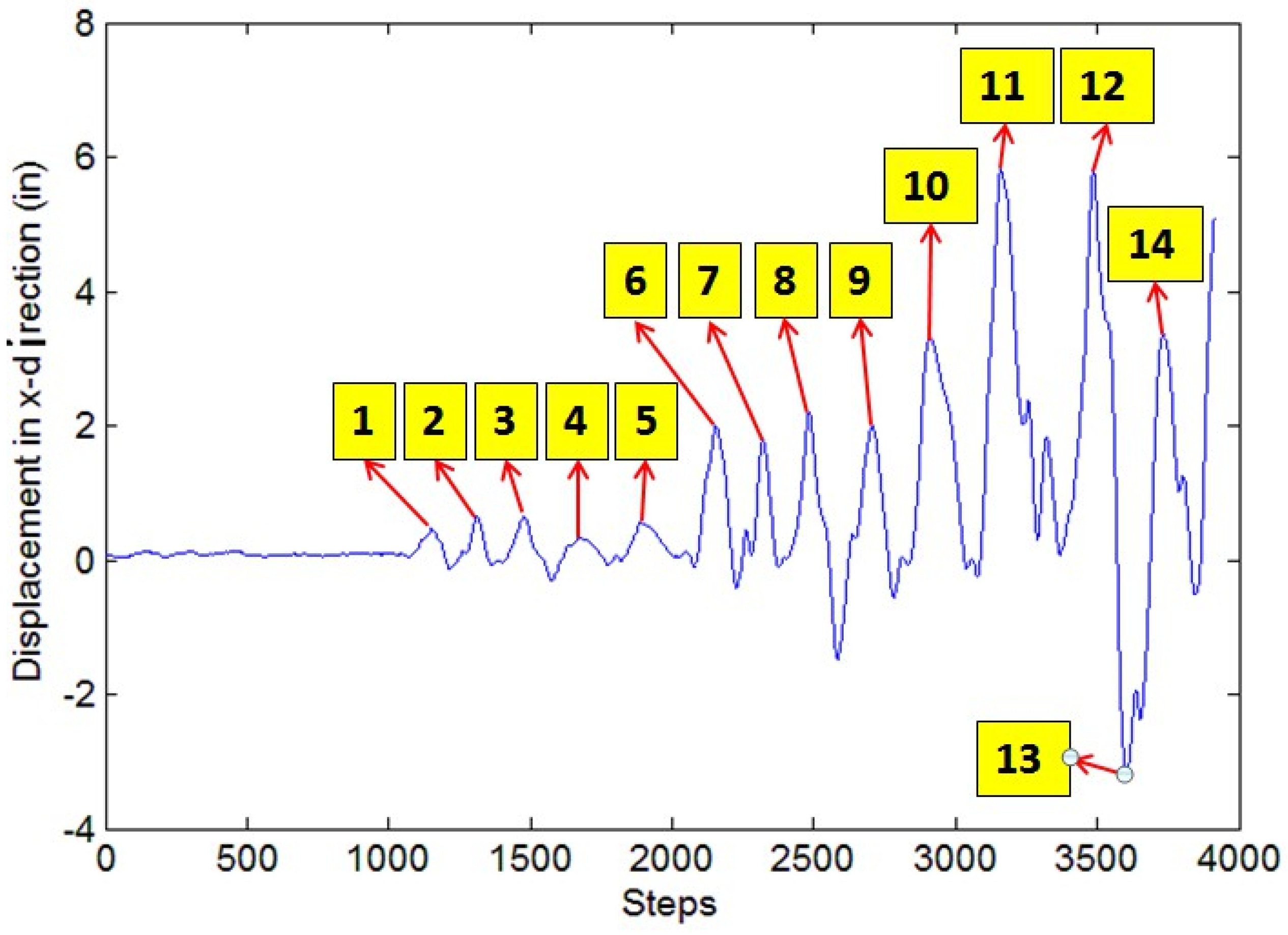
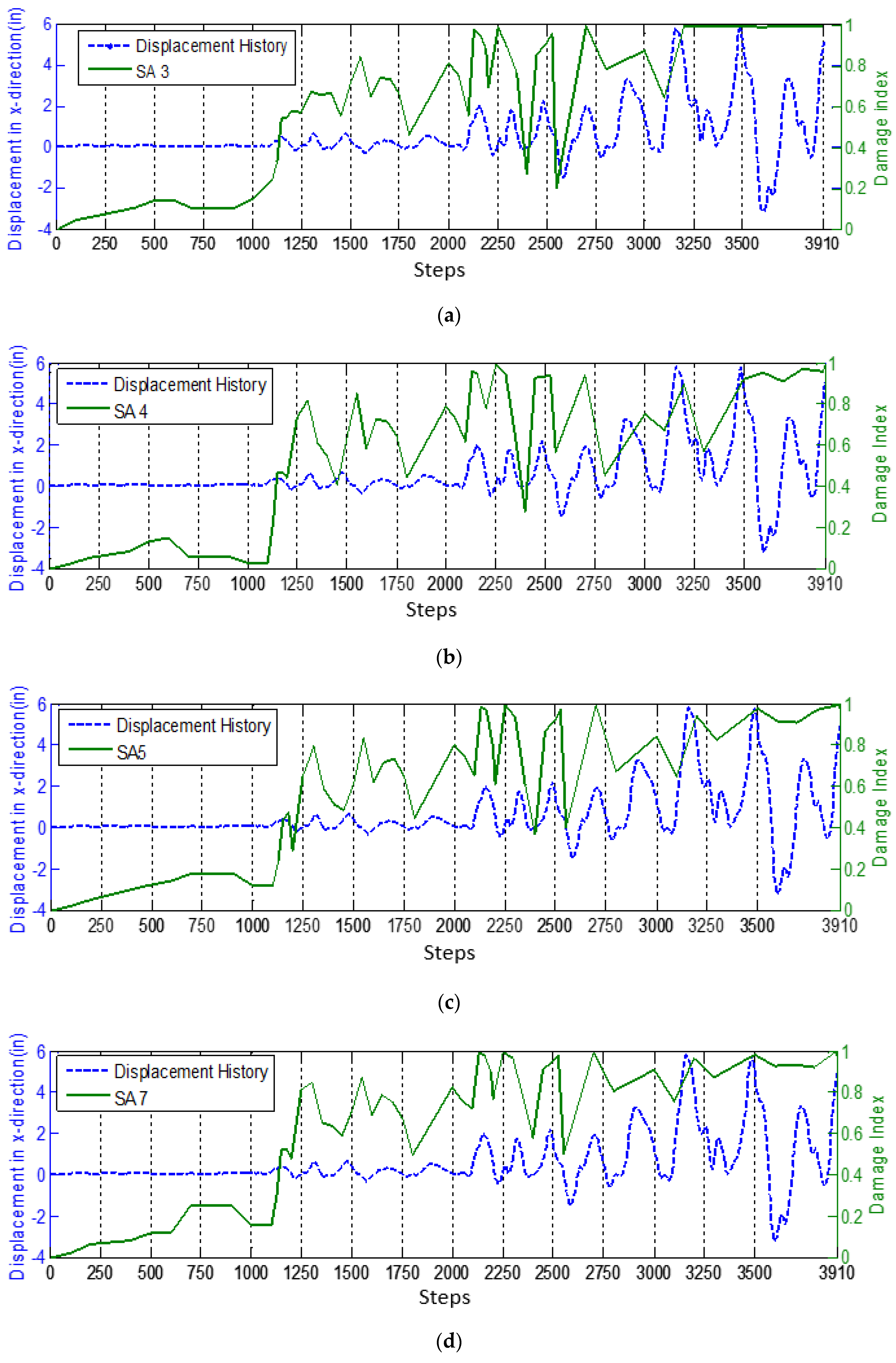
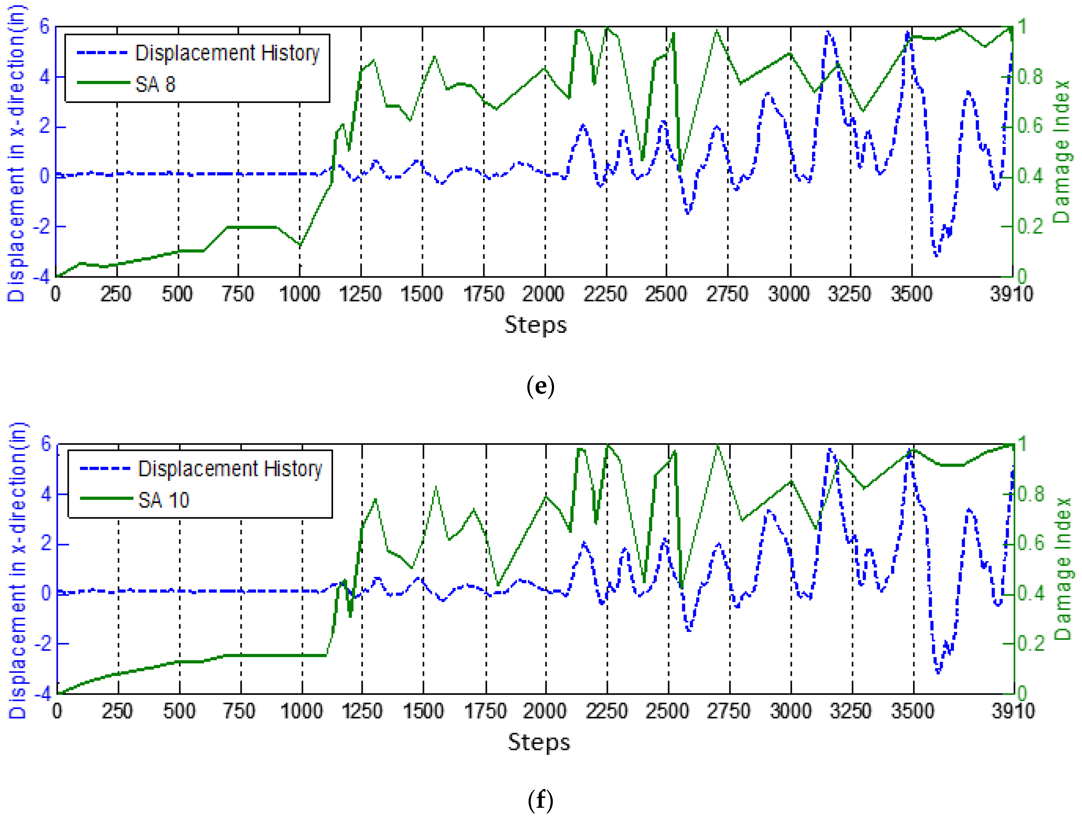
5.1. Loading History

The test was stopped due to the actuators in the x-direction running out of stroke. At that point, the concrete column had yielded and was exhibiting spalling, but had not yet failed. Figure 7 shows the force-displacement and moment-curvature relationships in the x-, y- and z-directions for the concrete column, respectively. A photo of the yielded concrete column after test is shown in Figure 8.
As shown in Figure 7, the x-direction had the largest displacement in the test. The displacement history in the x-direction at the top of the concrete column is shown in Figure 9. During the 40-h test, 14 cycles of displacement in the x-direction were observed and marked in Figure 9.

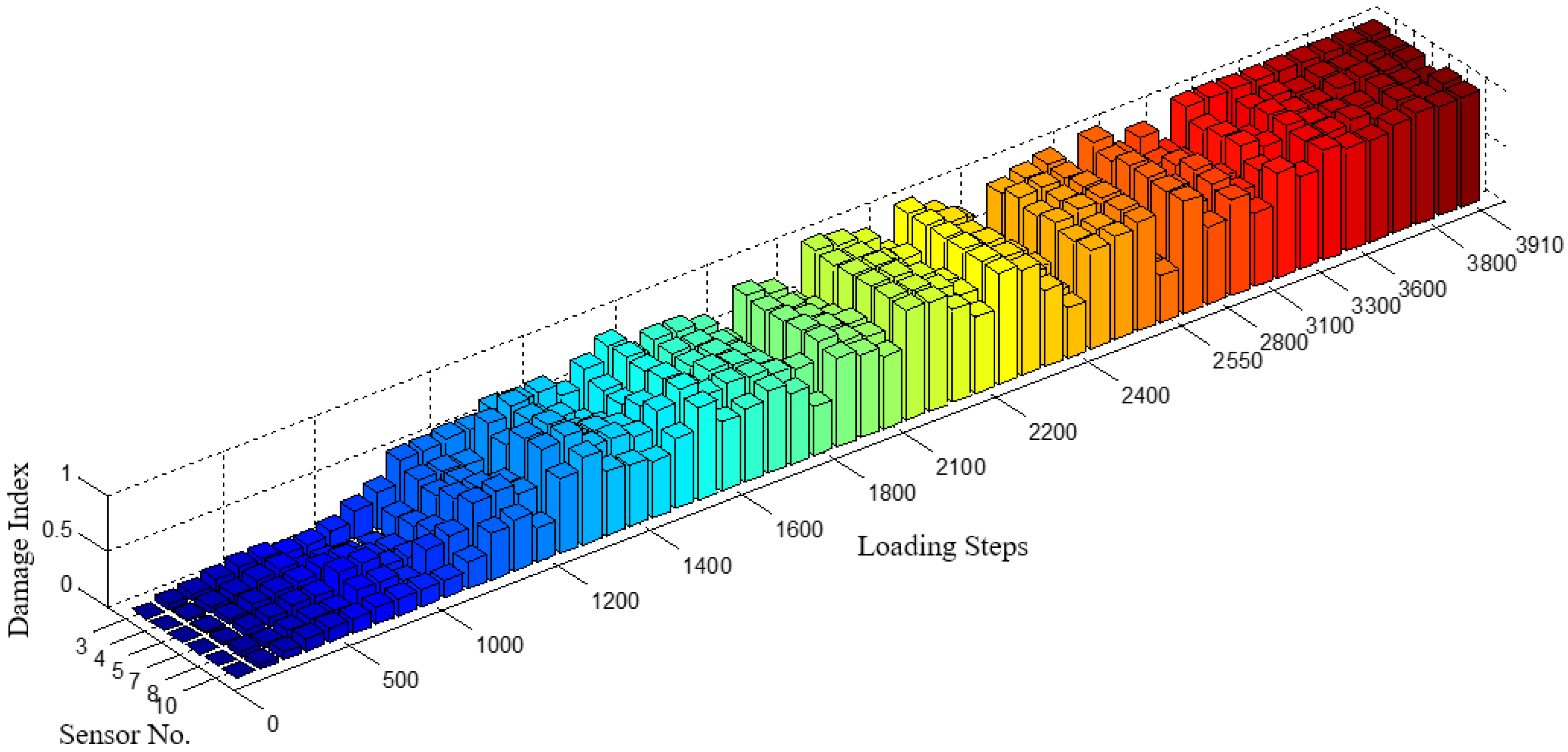
5.2. Wavelet Packet-Based Structural Damage Indices

During the test, SA-6 and SA-9 failed to function. The possible reason for the dead sensors may be that the wire broke during casting. Experimental results from the other sensors are shown below.
Figure 10 shows the wave packet-based damage indices of all the functional SA sensors during the test. The damage indices of each SA sensor present generally increasing values, which correspond to the damage development of the RC column. Before Step 1000, values of the damage indices are close to zero due to small displacement and damage within the RC column. As the load increased after Step 1000, the values of damage indices increase. After Step 3500, damage indices of all SA sensors report values close to one, which means the RC column sustained a high level of damage. The results shown in the damage indices are in good agreement with the test record [45].
Other than the general increasing trend shown in the damage indices, several local increasing and decreasing cycles can also be found in the damage indices. Since the RC column was subjected to cyclic loading, the cracks in the RC column opened and closed correspondingly. The local increasing and decreasing values shown in the damage indices detected this opening and closing of the cracks during the test. According to different cycles of increasing and decreasing shown in the damage indices, overlay plots of the displacement history curve and damage indices of each functional SA are shown Figure 11.
In the first 1000 steps, the displacement of the RC column was very small, as shown in Figure 9 (0–1000 steps). Since no damage occurred during this time, the received signal of SAs did not change much. Therefore, the values of the local damage indices are also very small, as shown in Figure 10 and Figure 11. It can be considered that the RC column was in good health during the first 1000 steps.
From Step 1100 to Step 2100, the concrete column was subject to five initial simulated pseudo-dynamic loading cycles (1–5), as shown in Figure 9. When load increased, the bottom cracks opened and the structural damage increased. When load decreased, cracks closed corresponding to the decreased damage. During this period, the peaks and valleys between the damage indices and the displacement history as shown in Figure 11 are not clearly matching to each other, but the similar increasing and decreasing trends can still be found. The possible reason is the crack open-close phenomenon in this period is not clear, since the crack formed at the bottom of the concrete column is very small under the first several loading cycles.
From Step 2100 to Step 3300, both the cycles observed in displacement history and the damage indices are in good agreement with each other. Since the highest value in each displacement cycle of the RC column was quite large, as shown in Figure 9, the major crack has existed at the bottom of the concrete column. As the concrete column was pushed to one side, the major crack opened and the values of the damage indices for each smart aggregate correspondingly increase. As the concrete column was further pushed back to its original position, the values of the damage indices decrease. Since the crack in this period is much larger than the previous step from 1100 to 2100, the propagating stress wave attenuates more than the previous period. The cycles (6–11) shown in the damage index are more clear than the previous cycles (1–5). In addition, the highest values of the damage index reached to one, which implies the concrete column was subject to severe damage in the maximum displacement of each cycle.
After Step 3300, the RC column almost reached the ultimate capability. In both cases in which the crack opened and closed, most of the propagating stress wave energy was attenuated. SA sensors “lost contact” with the actuator. The damage indices in this period, as shown in Figure 10 and Figure 11, do not continue to present the similar increasing and decreasing trends as before. As the load cycled, the values of damage indices of all the SA sensors maintained a constant value near one, which indicates that the major crack at the bottom of the concrete column cannot be “recovered” even when the RC column was pushed back to its original position.
As shown in Figure 11, the peaks and valleys between the damage indices and displacement history match well until approximately load Step 3250, which corresponds to the maximum load and severe damage in the column. Beyond this point, the damage indices maintain a value near one. Each peak corresponds to cracks opening and each valley corresponds to a cracks closing (or opening on the opposite side of the column).
In addition, the results using wavelet packet-based damage index are compared with both the strain energy of the RC column and the recorded key events presented by Frankie et al. [45]. The cycles of the structural strain curve shown in Frankie et al. [45] also agree with the cycles of the damage indices. After around Step 3200, the strain value of the RC column at the cracking area approaches to its maximum values and the values in our computed damage indices corresponding approach one, which implies that the RC column is under severe damage at this stage. On the other hand, from the observed key events shown in Frankie et al. [45], we can see that the first reported event of concrete cracking occurred at Step 1243. These results also agree with our damage indices, where we can see that the first obvious increase happens between Step 1000 and Step 1250. When the recorded concrete spalling event happens at Step 3261, the values of our damage indices correspondingly approach one. The agreement between our results and others’ show that the smart aggregate-based active sensing approach is capable of monitoring the crack opening and closing condition in real-time.

6. Conclusions

Under the pseudo-dynamic loading, the cracks in the RC column were subjected to cyclic opening and closing. Cracks, acting as stress relief, reduce the stress wave propagation energy throughout the column. The proposed SA-based active sensing approach successfully detects the crack development and crack open-close condition of the RC column in real-time. The general increasing values shown in damage indices can evaluate the damage severity of the RC column. When the values approach one, it means that the RC column has reached the ultimate capability. The phenomenon of crack opening and closing during the cycles of pseudo-dynamic loading is clearly presented in the local damage indices. In addition, the peaks and valleys in the damage indices and displacement history curves are in good agreement with each other, which enhances the application of the proposed approach in this paper. Potentially, our active sensing approach using smart aggregates could be further developed into a wireless structural health monitoring system that poses many engineering challenges with future studies.

Acknowledgments

The research was supported by an award (No. CMMI-0724190) from National Science Foundation (NSF). The opinions expressed in this study are those of the authors and do not necessarily reflect the views of the sponsor. The work done by Rachel Howser Roberts was completed while she was finishing her graduate degree at the University of Houston.

Author Contributions

Y.L. Mo and Pedro Silva conceived and designed the experiments. Pedro Silva, Qingzhao Kong, and Rachel Howser Roberts performed the experiments and collected the experimental data. Qingzhao Kong helped to fabricate the sensors and analyzed the data. Qingzhao Kong and Rachel Howser Roberts wrote the paper.

Conflicts of Interest

The authors declare no conflict of interest.

References

  1. Hong, S.; Cho, D.; Park, S.-K. Application of a new anchorage towards the flexural strengthening of RC rectangular beams with external steel tendons. Appl. Sci. 2016, 6. [Google Scholar] [CrossRef]
  2. Rizzo, P.; Nasrollahi, A.; Deng, W.; Vandenbossche, J.M. Detecting the presence of high water-to-cement ratio in concrete surfaces using highly nonlinear solitary waves. Appl. Sci. 2016, 6. [Google Scholar] [CrossRef]
  3. Agrawal, B.N.; Elshafei, M.A.; Song, G. Adaptive antenna shape control using piezoelectric actuators. IAF Acta Astronaut. J. 1997, 40, 821–826. [Google Scholar] [CrossRef]
  4. Meyer, J.; Harrington, B.; Agrawal, B.; Song, G. Vibration suppression of a spacecraft flexible appendage using smart material. Smart Mater. Struct. 1998, 7, 95–104. [Google Scholar] [CrossRef]
  5. Sethi, V.; Song, G. Optimal vibration control of a model frame structure using piezoceramic sensors and actuators. J. Vib. Control 2005, 11, 671–684. [Google Scholar] [CrossRef]
  6. Xu, B.; Zhang, T.; Song, G.; Gu, H. Active interface debonding detection of a concrete-filled steel tube with piezoelectric technologies using wavelet packet analysis. Mech. Syst. Signal Process. 2013, 36, 7–17. [Google Scholar] [CrossRef]
  7. Yuan, S.; Zhao, Y.; Chu, X.; Zhu, C.; Zhong, Z. Analysis and experimental research of a multilayer linear piezoelectric actuator. Appl. Sci. 2016, 6. [Google Scholar] [CrossRef]
  8. Gu, H.; Song, G.; Dhonde, H.; Mo, Y.L.; Yan, S. Concrete early-age strength monitoring using embedded piezoelectric transducers. Smart Mater. Struct. 2006, 15, 1837–1845. [Google Scholar] [CrossRef]
  9. Kong, Q.; Hou, S.; Ji, Q.; Mo, Y.L.; Song, G. Very early age concrete hydration characterization monitoring using piezoceramic based smart aggregates. Smart Mater. Struct. 2013, 22. [Google Scholar] [CrossRef]
  10. Song, G.; Olmi, C.; Gu, H. An overheight vehicle-bridge collision monitoring system using piezoelectric transducers. Smart Mater. Struct. 2007, 16, 462–468. [Google Scholar] [CrossRef]
  11. Gu, H.; Moslehy, Y.; Sanders, D.; Song, G.; Mo, Y.L. Multi-functional smart aggregate-based structural health monitoring of circular reinforced concrete columns subjected to seismic excitations. Smart Mater. Struct. 2010, 19, 2888–2898. [Google Scholar] [CrossRef]
  12. Kong, Q.; Wang, R.; Song, G.; Yang, Z.J.; Still, B. Monitoring the soil freeze-thaw process using piezoceramic-based smart aggregate. J. Cold Reg. Eng. 2014, 28. [Google Scholar] [CrossRef]
  13. Song, G.; Gu, H.; Mo, Y.L.; Hsu, T.T.C.; Dhonde, H. Concrete structural health monitoring using embedded piezoceramic transducers. Smart Mater. Struct. 2007, 16, 959–968. [Google Scholar] [CrossRef]
  14. Laskar, A.; Gu, H.; Mo, Y.L.; Song, G. Progressive Collapse of a 2-story Reinforced Concrete Frame. In Proceedings of the Earth and Space 2008: Engineering, Science, Construction, and Operations in Challenging Environments, Long Beach, CA, USA, 3–5 March 2008; pp. 1–9.
  15. Zhao, X.; Li, H. Health monitoring of reinforced concrete frame-shear wall using piezoceramic transducer. J. Vib. Shock 2006, 25, 82–84. [Google Scholar]
  16. Yan, S.; Sun, W.; Song, G.; Gu, H. Health monitoring of reinforced concrete shear walls using smart aggregates. Smart Mater. Struct. 2009, 18. [Google Scholar] [CrossRef]
  17. Liao, W.I.; Gu, H.; Olmi, C.; Song, G.; Mo, Y.L.; Loh, C.H. Structural Health Monitoring of a Concrete Column Subjected to Shake Table Excitations Using Smart Aggregates. In Proceedings of the Earth and Space 2008: Engineering, Science, Construction, and Operations in Challenging Environments, Long Beach, CA, USA, 3–5 March 2008; pp. 1–8.
  18. Siu, S.; Ji, Q.; Wu, W.; Song, G.; Ding, Z. Stress wave communication in concrete: I. Characterization of a smart aggregate based concrete channel. Smart Mater. Struct. 2014, 23, 125030. [Google Scholar] [CrossRef]
  19. Siu, S.; Qing, J.; Wang, K.; Song, G.; Ding, Z. Stress wave communication in concrete: II. Evaluation of low voltage concrete stress wave communications utilizing spectrally efficient modulation schemes with PZT transducers. Smart Mater. Struct. 2014, 23, 125031. [Google Scholar] [CrossRef]
  20. Moslehy, Y.; Gu, H.; Belarbi, A.; Mo, Y.L.; Song, G. Smart aggregate based damage detection of circular RC columns under cyclic combined loading. Smart Mater. Struct. 2010, 19, 140–158. [Google Scholar] [CrossRef]
  21. Howser, R.; Moslehy, Y.; Gu, H.; Dhonde, H.; Mo, Y.L.; Ayoub, A.; Song, G. Smart-aggregate-based damage detection of fiber-reinforced-polymer-strengthened columns under reversed cyclic loading. Smart Mater. Struct. 2011, 20. [Google Scholar] [CrossRef]
  22. Mehrani, E.; Ayoub, A.; Ayoub, A. Evaluation of fiber optic sensors for remote health monitoring of bridge structures. Mater. Struct. 2008, 42, 183–199. [Google Scholar] [CrossRef]
  23. Zhang, W.; Gao, J.; Shi, B.; Cui, H.; Zhu, H. Health monitoring of rehabilitated concrete bridges using distributed optical fiber sensing. Comput. Aided Civ. Infrastruct. Eng. 2006, 21, 411–424. [Google Scholar] [CrossRef]
  24. Chen, X.; Ansari, F. Fiber optic stress wave sensor for detection of internal flaws in concrete structures. J. Intell. Mater. Syst. Struct. 1999, 10, 274–279. [Google Scholar] [CrossRef]
  25. Hey, F.; Bhalla, S.; Soh, C.K. Optimized parallel interrogation and protection of piezo-transducers in electromechanical impedance technique. J. Intell. Mater. Syst. Struct. 2006, 17, 457–468. [Google Scholar] [CrossRef]
  26. Tseng, K.K.; Wang, L. Smart piezoelectric transducers for in situ health monitoring of concrete. Smart Mater. Struct. 2004, 13, 1017–1024. [Google Scholar] [CrossRef]
  27. Providakis, C.P.; Voutetaki, M.E. Electromechanical admittance—Based damage identification using Box-Behnken design of experiments. Struct. Durab. Health Monit. 2007, 3, 211–227. [Google Scholar]
  28. Karayannis, C.G.; Voutetaki, M.E.; Chalioris, C.E.; Providakis, C.P.; Angeli, G.M. Detection of flexural damage stages for RC beams using piezoelectric sensors (PZT). Smart Struct. Syst. 2015, 15, 997–1018. [Google Scholar] [CrossRef]
  29. Park, S.; Ahmad, S.; Yun, C.-B.; Roh, Y. Multiple crack detection of concrete structures using impedance-based structural health monitoring techniques. Exp. Mech. 2006, 46, 609–618. [Google Scholar] [CrossRef]
  30. Chalioris, C.E.; Papadopoulos, N.A.; Angeli, G.M.; Karayannis, C.G.; Liolios, A.A.; Providakis, C.P. Damage evaluation in shear-critical reinforced concrete beam using piezoelectric transducers as smart aggregates. Open Eng. 2015, 1, 373–384. [Google Scholar] [CrossRef]
  31. Bhalla, S.; Soh, C.K. High frequency piezoelectric signatures for diagnosis of seismic/blast induced structural damages. NDT E Int. 2004, 37, 23–33. [Google Scholar] [CrossRef]
  32. Raju, V.; Gyuhae, P.; Cudney, H.H. Impedance-Based Health Monitoring of Composite Reinforced Structures. In Proceedings of the 9th International Conference on Adaptive Structures and Technologies, Boston, MA, USA, 14–16 October 1998; pp. 448–457.
  33. Soh, C.K.; Tseng, K.K.-H.; Bhalla, S.; Gupta, A. Performance of smart piezoceramic patches in health monitoring of a RC bridge. Smart Mater. Struct. 2000, 9, 533–542. [Google Scholar] [CrossRef]
  34. Providakis, C.P.; Stefanaki, K.D.; Voutetaki, M.E.; Tsompanakis, Y.; Stavroulaki, M. Damage detection in concrete structures using a simultaneously activated multi-mode PZT active sensing system: Numerical modelling. Struct. Infrastruct. Eng. 2014, 10, 1451–1468. [Google Scholar] [CrossRef]
  35. Chalioris, C.E.; Karayannis, C.G.; Angeli, G.M.; Papadopoulos, N.A.; Favvata, M.J.; Providakis, C.P. Applications of smart piezoelectric materials in a wireless admittance monitoring system (WiAMS) to structures—Tests in RC elements. Case Stud. Constr. Mater. 2016, 5, 1–18. [Google Scholar] [CrossRef]
  36. Voutetaki, M.E.; Papadopoulos, N.A.; Angeli, G.M.; Providakis, C.P. Investigation of a new experimental method for damage assessment of RC beams failing in shear using piezoelectric transducers. Eng. Struct. 2016, 114, 226–240. [Google Scholar] [CrossRef]
  37. Karayannis, C.G.; Chalioris, C.E.; Angeli, G.M.; Papadopoulos, N.A.; Favvata, M.J.; Providakis, C.P. Experimental damage evaluation of reinforced concrete steel bars using piezoelectric sensors. Constr. Build. Mater. 2016, 105, 227–244. [Google Scholar] [CrossRef]
  38. Divsholi, B.S.; Yang, Y. Combined embedded and surface-bonded piezoelectric transducers for monitoring of concrete structures. NDT E Int. 2014, 65, 28–34. [Google Scholar] [CrossRef]
  39. Okafor, A.C.; Chandrashekhara, K.; Jiang, Y.P. Delamination prediction in composite beams with built-in piezoelectric devices using modal analysis and neural network. Smart Mater. Struct. 1996, 5, 338–347. [Google Scholar] [CrossRef]
  40. Song, G.; Gu, H.; Mo, Y.L. Smart aggregates: Multi-functional sensors for concrete structures—A tutorial and a review. Smart Mater. Struct. 2008, 17. [Google Scholar] [CrossRef]
  41. Saafi, M.; Sayyah, T. Health monitoring of concrete structures strengthened with advanced composite materials using piezoelectric transducers. Compos. B Eng. 2001, 32, 333–342. [Google Scholar] [CrossRef]
  42. Miller, T.; Hauser, C.J.; Kundu, T. Nondestructive Inspection of Corrosion and Delamination at the Concrete-Steel Reinforcement Interface. In Proceedings of the ASME 2002 International Mechanical Engineering Congress and Exposition, New York, NY, USA, 17–22 November 2002; pp. 121–128.
  43. Na, W.-B.; Kundu, T. Inspection of interfaces between corroded steel bars and concrete using the combination of a piezoelectric zirconate-titanate transducer and an electromagnetic acoustic transducer. Exp. Mech. 2003, 43, 24–31. [Google Scholar] [CrossRef]
  44. Hera, A.; Hou, Z. Application of wavelet approach for ASCE structural health monitoring benchmark studies. J. Eng. Mech. 2004, 130, 96–104. [Google Scholar] [CrossRef]
  45. Frankie, T.M. Impact of Complex System Behavior on Seismic Assessment of RC Bridges. Ph.D. Thesis, University of Illinois at Urbana-Champaign, Champaign, IL, USA, 22 August 2013. [Google Scholar]
Figure 1. Structure of a smart aggregate.
Applsci 06 00341 g001
Figure 2. Schematic diagram of smart aggregate-based active sensing approach.
Applsci 06 00341 g002
Figure 3. Location of smart aggregates in the concrete column.
Applsci 06 00341 g003
Figure 4. (a) A smart aggregate fixed on the rebar cage; (b) A smart aggregate was installed in the base.
Applsci 06 00341 g004
Figure 5. The concrete column specimen after casting.
Applsci 06 00341 g005
Figure 6. Loading protocol: acceleration record.
Applsci 06 00341 g006
Figure 7. Force-displacement and moment-curvature relationships in the x-, y- and z-directions. (a) Force-displacement relationships; (b) Moment-curvature relationships.
Applsci 06 00341 g007
Figure 8. A photo of the concrete column yielding after test.
Applsci 06 00341 g008
Figure 9. Displacement history in x-direction of the column.
Applsci 06 00341 g009
Figure 10. General damage indices throughout the test.
Applsci 06 00341 g010
Figure 11. Overlap plots of damage indices and displacement history curves: (a) SA 3; (b) SA 4; (c) SA 5; (d) SA 7; (e) SA 8; (f) SA 10.
Applsci 06 00341 g011aApplsci 06 00341 g011b
Table 1. The detailed parameters of the lead zirconate titanate (PZT) patch.
PZT TypeParametersValuesUnit
PZT-5HDimension10 × 10 × 1mm
Density7800kg·m−3
Young’s modulus46 × 109Pa
Poisson’s ratio0.3-
Piezoelectric strain coefficients d334.9510−10 m·V−1

