Article

Study on the Load Distribution and Dynamic Characteristics of a Thin-Walled Integrated Squirrel-Cage Supporting Roller Bearing

School of Mechatronics Engineering, Harbin Institute of Technology, Harbin 150001, China
*
Author to whom correspondence should be addressed.
Appl. Sci. 2016, 6(12), 415; https://doi.org/10.3390/app6120415
Submission received: 7 October 2016 / Revised: 2 December 2016 / Accepted: 3 December 2016 / Published: 14 December 2016
(This article belongs to the Special Issue Applications of Thin-Walled Structures)

Abstract

:
Thin-walled integrated flexible support structures are the major trend in the development of current rolling bearing technology. A thin-walled, integrated, squirrel-cage flexible support roller bearing, quasi-dynamic iterative finite element analysis (FEA) model is established in this paper. The FEA model is used to calculate the structural deformation of the thin-wall rings and support structures; the dynamic characteristics of the bearing are analyzed using the noncircular bearing modified quasi-dynamic model. The influence of the integrated flexible support structure on the internal load distribution and the dynamic characteristics of the roller bearing are analyzed. The results indicate that with the support of a flexible squirrel-cage, the maximum contact load is decreased by 14.2%, the loading region is enlarged by 25%, the cage slide ratio is reduced by 24%, and the fatigue life is increased by more than 50%. In addition, as the ring wall thickness increased, the results increasingly approached those under a rigid assumption.

1. Introduction

Advanced rolling bearing technology is one of the basic strategic industries and core technologies in high-speed systems and the aerospace field. The use of thin walls, lightweight structures, and component integration represent major trends in the development of advanced rolling bearing technologies [1]. As a main technological trend in the field of high-speed bearings, the integrated squirrel-cage flexible support roller bearing is a thin-wall bearing with a squirrel-cage structure connected to the outer ring and a hollow shaft assembled in the inner ring. In this type of structure, the hollow shaft, bearing ring, and squirrel-cage flexible support structures are all thin-walled, and, as a result, easily produce elastic structural deformations under load; this induces a change in the internal load distribution of the bearing, and leads to a significant influence on the characteristics of the bearing dynamics, which should not be neglected.
Based on the Hertz theoretical calculation model, Jones [2] built a static model and calculated the load distribution of rolling bearing. Subsequently, many researchers studied the behaviors of rolling bearings [2,3,4,5], however, most of their methods are built using the rigid structure hypothesis, considering the rings as constant geometry parts, and ignoring the elastic deformations of the structures under load. Thus, these rigid structure assumption models cannot fully meet the demands of the continued development of rolling bearings, because the structural deformation of thin-walled rings and flexible supports is much more pronounced. Thus, it is essential to carry out dynamic performance analyses of the integrated squirrel-cage flexible support bearing in the study of current high-end bearing usage.
Broschard [6] established a flexible bearing model for planetary gear, while Shen [7] built a flexible bearing model for harmonic gear. However, these two models are only for bearings in planetary gear transmission or harmonic gear transmission, which are quite different from the flexible support bearings in high-speed shaft systems. Lostado [8] analyzed the contact stress of the double-row tapered roller bearings using the finite element method; experimental analyses and an analytical model shows that the finite element method could be very accurate in bearing stress calculations. Yao [9] used the curved Timoshenko beam (CTB) theory to calculate the structural deformation of a thin-walled bearing ring, and analyzed the load distribution of thin-walled roller bearing; however, the model, assumed that the rings are supported at one or two azimuth positions only, and did not consider the specific form of the bearing support. Researchers, such as Ignacio [10], Kania [11], Olave [12], Shu Ju [13] and Liu [14], used the finite element method to analyze the structural deformation of thin-walled rings, but such a method cannot take into account the contact mechanics and the lubrication status between the rollers and the raceway. Moreover, a method in which linear springs are used to replace rolling elements cannot provide an accurate internal loading solution, because the load-deflection factor is non-linear, and the centrifugal effort in high-speed bearing is very difficult to simulate by a spring element, and it would be very complicated when the bearing has clearances because the number of loading rollers is unknown [15]; thus, it was difficult to precisely analyze the dynamic performance of the bearing.
In this paper, an integrated squirrel-cage flexible support roller bearing iterative quasi-dynamic finite element analysis (FEA) model is established. This model is used to comprehensively consider the effects of contact mechanics, lubrication, and structural deformations. The model can accurately predict the dynamic performance of the integrated squirrel-cage flexible support roller bearing. The standard circular rolling bearing quasi-dynamic model is modified in order to obtain the modified noncircular rolling bearing quasi-dynamic model. The integrated squirrel-cage flexible support roller bearing finite element model is constructed using ANSYS software (ANSYS 12.0, ANSYS Corporation, Canonsburg, PA, USA), and is used to calculate the deformation of the bearing ring and squirrel-cage structure. The calculated deformations are inserted into the noncircular rolling bearing quasi-dynamic modified model in order to obtain load distribution and dynamic characteristic analysis results of the bearing.

2. Model Design

2.1. Modified Noncircular Rolling Bearing Quasi-Dynamic Model

Quasi-dynamic analysis is an accurate bearing analysis method, because it comprehensively considers the microscopic contact and the rheological characteristics of the lubricant. Quasi-dynamic analysis can accurately calculate the dynamic characteristics of a rigid rolling bearing, but is not suited for a flexible bearing, of which the raceways would be noncircular following structural deformation; thus, a modified quasi-dynamic model for noncircular rolling bearings is needed.
Figure 1 shows a sketch of the force of roller bearing. Cutting the roller into slices, the k-th slice of the j-th roller experiences contact forces Q 1 j k and Q 2 j k , and drags forces T 1 j k and T 2 j k from the inner and outer raceways through oil films, normal force F c j and tangential force f c j from the cage, and oil–gas mixture frictional force F g j , as well as its own inertial force, F z j , and inertia moment M x j due to rolling.
According to the Hertz theory, forces Q 1 j k and Q 2 j k between the roller slice and the raceways can be obtained from contact approaches δ 1 j k and δ 2 j k of the slice and raceways, respectively. When the ring deforms, the raceway becomes a nonideal cylindrical surface. The deviations of the k-th slice of the j-th roller at the local surface from the ideal cylindrical surface can be expressed as δ 1 j k h and δ 2 j k h . These two deviations can be superimposed with approaches δ 1 j k and δ 2 j k , based on the small deformation assumption. By further considering oil film thickness h 1 j k and h 2 j k at the contact area, the actual contact approaches, δ 1 j k and δ 2 j k , between the roller slice and the noncircular raceway can be obtained. Thus, contact loads Q 1 j k and Q 2 j k of the rolling object and the noncircular raceway can be obtained, as expressed in Equation (1). C k is the correction of the roller radius, considering the Roller Profile Modification and chamfer [16]. In addition, the roller balance equation can be established as Equation (2). The lubricant parameters in the model are calculated using the Hertz contact theory, the Dowson-Higginson formula [17], and the five-parameter rheological model [18]. The five-parameter rheological model has been experimentally verified and contains the viscosity–pressure property and the viscosity–temperature property of the oil.
δ 1 j k = δ 1 j k + h 1 j k + δ 1 j k h + C k Q 1 j k = ( δ 1 j k l e 0.8 3.81 ) 1 / 0.9 ( π E 1 2 ( 1 υ 1 2 ) ) δ 2 j k = δ 2 j k + h 2 j k + δ 2 j k h + C k Q 2 j k = ( δ 2 j k l e 0.8 3.81 ) 1 / 0.9 ( π E 2 2 ( 1 υ 2 2 ) ) C k = { 0 ;   l e l s 2 ( k 0.5 ) l e n l e + l s 2 ( R 2 l s 2 4 ) 0.5 ( R 2 x k 2 ) 0.5 ;   0 < k < l e l s 2 l e + l s 2 < k < l e
1 n k = 1 n ( T 1 j k T 2 j k + P 1 j k P 2 j k ) + F c j + F g j + F y j = 0 1 n k = 1 n ( Q 1 j k + Q 2 j k ) f c j + F z j = 0 D w 2 ( 1 n k = 1 n ( T 1 j k + T 2 j k ) f c j ) + M x j = 0 1 n k = 1 n ( Q 1 j k x k + Q 2 j k x k ) + M y j = 0 1 n k = 1 n ( P 1 j k x k + P 2 j k x k ) + M z j = 0
Variable δ 1 j k h and δ 2 j k h can be obtained based on the geometric shape of the deformed raceways, thus, with the rollers’ loads on the inner ring and the applied load of the ring from the shaft, the ring balance equation can be obtained, as expressed in Equation (3). The cage balance equation can be obtained using the method of Cui [16]. Thus, the modified noncircular ring bearing quasi-dynamic model is established.
F y F l r sin ψ F l t cos ψ j = 1 N ϖ k = 1 n Q 2 j k l e sin ϕ j = 0 F z F l r cos ψ F l t sin ψ j = 1 N ϖ k = 1 n Q 2 j k l e cos ϕ j = 0 M y j = 1 N ( ϖ k = 1 n Q 2 j k l e ) k = 1 n Q 2 j k [ ( k 0.5 ) ϖ 0.5 l e ] k = 1 n Q 2 j k cos ϕ j = 0 M z j = 1 N ( ϖ k = 1 n Q 2 j k l e ) k = 1 n Q 2 j k [ ( k 0.5 ) ϖ 0.5 l e ] k = 1 n Q 2 j k sin ϕ j = 0 M x D m 2 j = 1 N ( ϖ k = 1 n ( T 2 j k + P 2 j k ) ) = 0
The proposed model can be used to accurately analyze the load distribution and dynamic characteristics of the deformed bearing by taking into consideration the influence of the noncircular raceway following structural deformation, and also the microscopic contact and the rheological lubricant properties in the bearing. By setting the values of δ 1 j k h and δ 2 j k h as zero, this model can also analyze load distribution without structural deformations, which can be the initial values of finite element analysis.

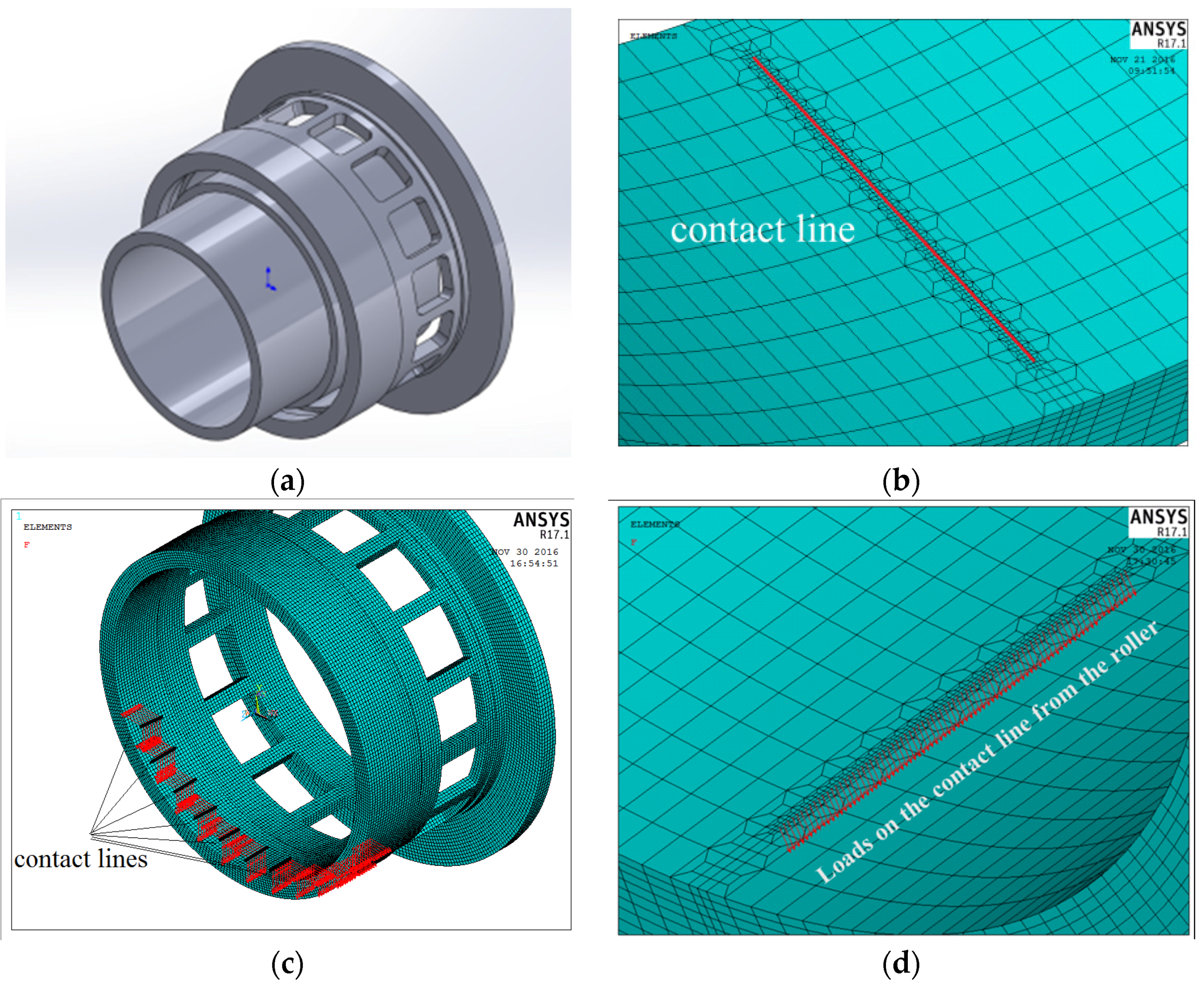
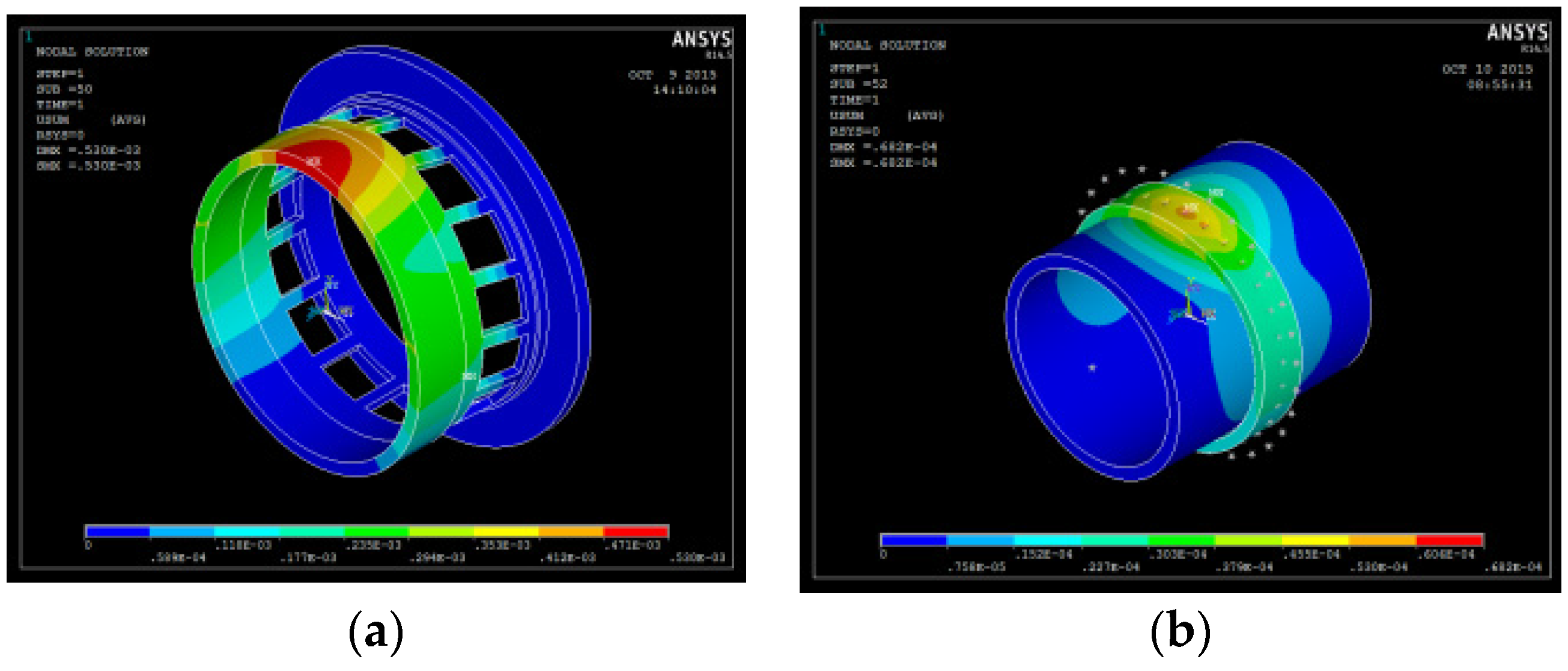
2.2. Finite Element Analysis of Integrated Squirrel-Cage Structural Deformation

An integrated squirrel-cage flexible support roller bearing includes a roller bearing, a hollow shaft, and a squirrel-cage support structure, and all components are thin-walled, as shown in Figure 2a. The shaft is assembled in the inner ring. The outer ring and the squirrel-cage structure are one integrated component, which means the outer ring is a part of the squirrel-cage structure, and the outer raceway is manufactured on the internal surface of the cylinder of the squirrel-cage structure. A finite element model containing a thin-walled hollow shaft, an inner bearing ring, and an outer ring-squirrel-cage support structure was constructed in ANSYS.
Boolean operation of the assembly was conducted in order to ensure satisfaction of the hexahedral meshing conditions, and three-dimensional object element meshing is achieved with SOLID45 elements. The mesh size has a great influence on the accuracy of the calculation [19]. The dimensions of contact areas are on the micrometer scale and the overall dimension of the bearing is in the millimeter scale. Thus, after meshing the whole assembly, the contact lines on the inner and outer raceway is re-mashed twice with smaller mesh sizes, so it is more accurate in imposing a load, as shown in Figure 2b.
To accurately reflect the relationship between the inner ring and the shaft, contact pairs are placed between the inner surface of the inner ring and the outer surface of the shaft, and between the side of the inner ring and the shaft shoulder. The contact method is surface-to-surface, and the friction coefficient is 0.1 [13]. The outer ring and the squirrel-cage structure are one integrated component, thus there is no contact pair. Designating the inner surface and the side surface of the inner ring as the contacting surface and the corresponding shaft outer surface and shaft shoulder as the target surface, respectively, the mutual contacting portion is described by TARGE170 and CONTA174 surface–surface contact elements. Targe170 is used to represent various 3-D “target” surfaces for the associated contact elements, and CONTA174 is used to represent contact and sliding between 3-D “target” surfaces and a deformable surface defined by this element.
The contact loads on the raceway from the rollers are calculated using the modified quasi-dynamic model, and the calculated loads are added to the contact line in the FEA model, as shown in Figure 2c,d. The squirrel-cage base surface is restricted to zero degrees of freedom. The shaft’s two end faces are restricted to zero degrees of freedom, and the inner ring is restricted on the shaft by contact pairs. There are no other constraints in this model, thus, it can deform under forces. Solving the model, the flexure and torsion deformations of the squirrel-cage structure and the thin-walled ring, as well as the resultant internal stress due to structural deformation, can be analyzed. In addition, the values of δ 1 j k h and δ 2 j k h in the modified quasi-dynamic model are obtained.

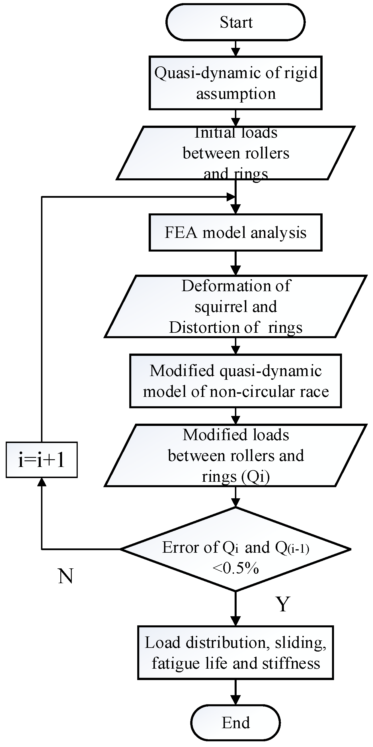
2.3. Iterative Quasi-Dynamic FEA Model

The initial values of internal bearing loads Q 1 j k and Q 2 j k are calculated using the modified quasi-dynamic model of noncircular bearing under the assumption of rigidity; the values of δ 1 j k h and δ 2 j k h are set as zero. These loads are inserted into the FEA model in order to calculate the local offset of each of the slice/raceway contact points ( δ 1 j k h and δ 2 j k h ). These offsets are substituted into the modified noncircular quasi-dynamic model via Equation (1) in order to recalculate raceway loads Q 1 j k and Q 2 j k , and they are then inserted into the finite element model once again. These steps are repeated until the load values satisfy the convergence precision.
The quasi-dynamic iterative FEA model analysis flow is shown in Figure 3. When the results converge, the load distribution of the bearing, with consideration to the structural deformation of the integrated squirrel-cage flexible support, can be obtained. Furthermore, the dynamic characteristics of the bearing, and the stiffness of the entire structure, including squirrel-cage stiffness and the deformed bearing stiffness, can be obtained. The fatigue life can be calculated by the Harris improved Lundberg-Palmgren (L-P) theory. The Harris improved L-P theory is based on the L-P theory and contains the load distribution and lubrication of the bearing [2].

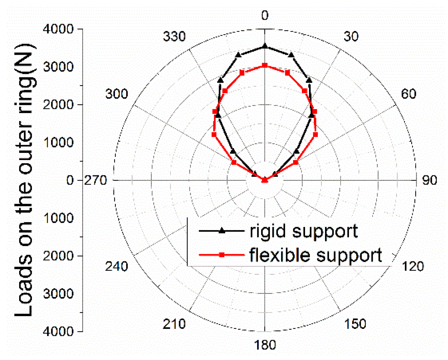
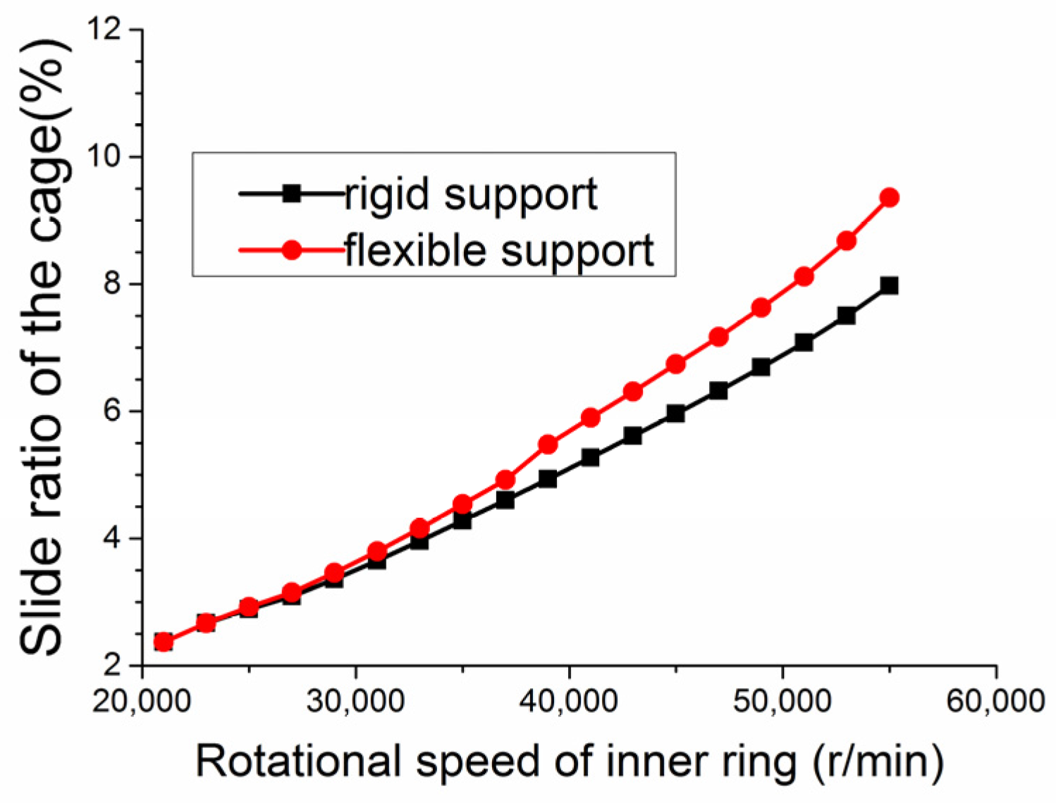
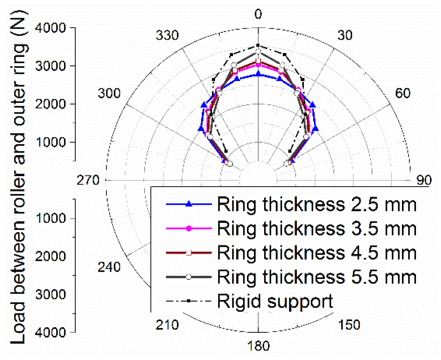
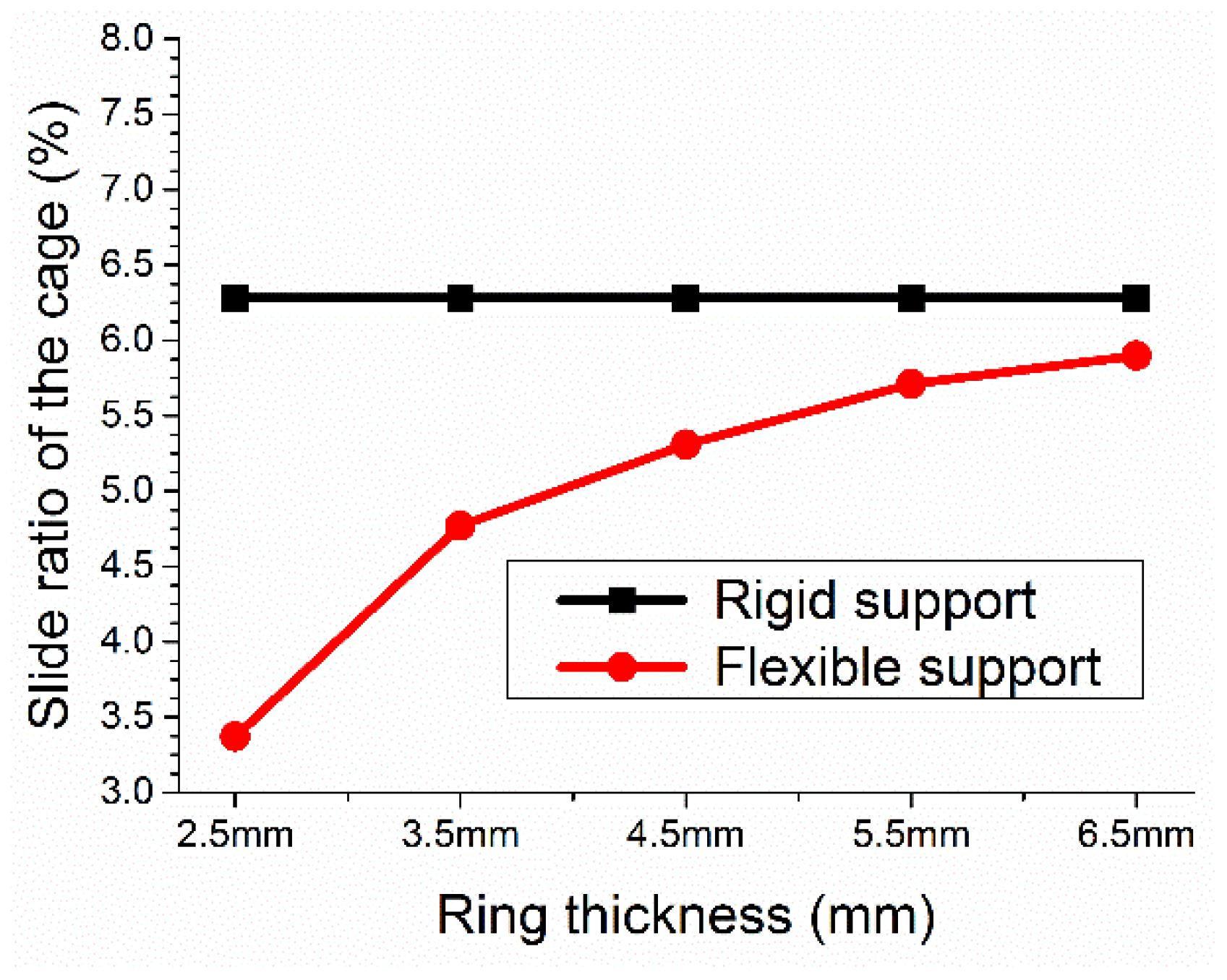
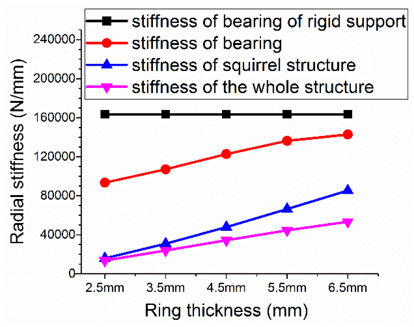
3. Results and Discussion

An integrated squirrel-cage support roller bearing is used as an example to analyze the influence of structural deformation on the load distribution, dynamic behavior, and fatigue life of the bearing. The parameters of the bearing are given in Table 1, Table 2 and Table 3, and the numerical values of the analysis results depend on the geometry of the bearing.
The temperature of the components can influence the rheological behavior of the oil and the internal clearance of the bearing; thus, it is necessary to consider the temperature of each of the bearing components. Additionally, the FEA model is built with dimensions after heat expansion.
Consideration the influence of structural deformations, the abovementioned quasi-dynamic iterative FEA model is used to calculate the load distribution of the bearing. The FEA model has 1.3 million elements, and the mesh size on the contact areas of raceway is 0.11 mm, while that of the bearing body is 0.8 mm. A computer with two CPU (Central Processing Unit) (Intel Xeon E5-2650, octa-core, 2.00 GHz, Intel Corporation, Santa Clara, CA, USA) and 64 GB Random-Access Memory (RAM) was used to simulate this model. 20 minutes were needed to preprocess the model, and, during each iteration, 10 to 15 minutes were needed to solve. The quasi-dynamic model is built using MATLAB (MATLAB R2013b, MathWorks Corporation, Natick, MA, USA), and, during each iteration, two minutes were required to solve. After 73 iterations, the load distribution reached convergence.
Figure 4 shows the deformation of the structure, and the equivalent radious R 1 , R 2 of the raceways are calculated and depicted in Figure 5. The maximum radial deviation between the equivalent radius and the original radius is 0.01428 mm.
The calculated results are compared to those based on the rigidity assumption, without consideration of the influence of the structural deformation. The load distribution of the bearing is shown in Figure 6.
It can be seen from the above results that, compared to the results calculated under the rigid support assumption, the maximum roller/raceway load decreased to 3035 N from 3537 N due to the influence of the deformation of the flexible squirrel-cage support structure, representing a decrease of 14.2%. Moreover, the internal bearing load is distributed more evenly. The number of loaded rollers decreased to 9 from 11, so the loading range is enlarged to 120° (−60°~60°) from 96° (−48°~48°), representing an increase of 25%.
Because bearing sliding is strongly dependent on the roller/raceway load, the change in the load distribution alters the bearing slide ratio. Compared to the rigid support, the bearing cage slide ratio under the flexible support decreased from 6.28% to 4.77%, representing a decrease of 24.05%. Figure 7 shows the slide ratio distribution of each roller.
Figure 8 shows the changes observed for the bearing cage slide ratio due to variations in the rotational speed. As the rotational speed increased, the cage sliding decreased by a greater percentage.
Figure 9 shows the influence of the change in thickness of the outer ring on the load distribution of the bearing. As the outer ring increases in thickness, the load distribution more closely approached the calculation result obtained under the rigid assumption; conversely, as the outer ring became thinner, the influence of structural deformation increased significantly.
Figure 10 shows the cage slide ratio due to different ring thicknesses. It can be seen that under the rigid assumption, the ring wall thickness does not influence the cage sliding. After considering the deformation of the structure, the cage slide ratio decreased by 8.3%~47.2%; in addition, as the ring wall thickness decreased, the cage slide ratio was reduced.
Figure 11 shows the bearing fatigue life. It can be seen that under the rigid assumption, the ring thickness does not influence fatigue life. After considering the structural deformation, the fatigue life increased by 33.8%~76.4%; in addition, as the ring thickness increased, the fatigue life was reduced, increasingly approaching that under the rigid assumption.
Figure 12 shows the radial stiffness. When the influence of the deformation of the structure is considered, the stiffness of the bearing is decreased because the bearing stiffness depends on the contact mechanics of the rollers and the raceways, which change following structural deformation.
The stiffness of the squirrel-cage is only 8.3%~32.7% that of the bearing, reducing the stiffness of the entire structure by an order of magnitude compared to that under the rigid assumption. In addition, as the ring wall thickness increased, the stiffness approached that under the rigid assumption.

4. Conclusions

(1) In this paper, an integrated squirrel-cage flexible support roller bearing quasi-dynamic iterative finite element analysis (FEA) model is established. The influence of deformed raceways is added to the bearing quasi-dynamic model, from which a noncircular raceway roller bearing quasi-dynamic-modified model is obtained. The modified model is coupled with a finite element model, which can calculate the elastic deformation of the squirrel-cage and the rings.
(2) Analyses of an integrated squirrel-cage flexible support roller bearing indicate that the squirrel-cage support structure can effectively reduce the maximum contact load between the rollers and raceways, and can load more rollers, thereby distributing the load more evenly and prolonging fatigue life.
(3) The proposed model is used to analyze the influence of ring thickness on the dynamic performance of the bearing. The results indicate that, the thicker the ring wall is, the closer the load distribution is to the calculation results obtained under the rigid assumption; in contrast, as the ring wall becomes thinner, the influence of the structural deformation becomes increasingly significant.
(4) The integrated squirrel support structure significantly reduces stiffness; thus, when used in a high-speed shaft system, the loading performance of the bearing and the impact on the overall stiffness of the integrated squirrel-cage support structure must also be comprehensively considered.

Acknowledgments

This work was supported in part by the National Natural Science Foundation of China (51375108), and the National Key Basic Research Program (2013CB632305).

Author Contributions

All authors made significant contributions to this article. Yuze Mao wrote the source code and revised the article; Liqin Wang was mainly responsible for checking the data and performing the revision of the paper; Chuanwei Zhang was responsible for developing the FEA model.

Conflicts of Interest

The authors declare no conflicts of interest.

References

  1. Zhao, L.; Sun, Y. The fault diagnosis of aero-engine main shaft bearings. Aircr. Des. 2010, 4, 46–50. [Google Scholar]
  2. Harris, T.A. Rolling Bearing Anaysis; John Wiley & Sons. Inc.: New York, NY, USA, 2007. [Google Scholar]
  3. Ebert, F.-J. An Overview of Performance Characteristics, Experiences and Trends of Aerospace Engine Bearings Technologies. Chin. J. Aeronaut. 2007, 20, 378–384. [Google Scholar] [CrossRef]
  4. Hakan, A.; Aydin, B.; Hasan, S. An investigation of tribological behaviors of dynamically loaded non-grooved and micro-grooved journal bearings. Tribol. Int. 2013, 58, 12–19. [Google Scholar]
  5. Oswald, F.B.; Zaretsky, E.V.; Poplawski, J.V. Interference-Fit Life Factors for Ball Bearings. Tribol. Trans. 2010, 54, 1–20. [Google Scholar] [CrossRef]
  6. Broschard, J. Analysis of an improved planetary gear transmission bearing. ASME Trans. J. Basic Eng. 1964, 86, 457–461. [Google Scholar]
  7. Shen, Y.; Zhang, T. Vibration Analysis of Flexible Rolling Bearing. Mech. Sci. Technol. Aerosp. Eng. 1995, 5, 1–6. [Google Scholar]
  8. Yao, T.; Chi, Y.; Huang, Y. Research on flexibility of bearing rings for multibody contact dynamics of rolling bearings. Procedia Eng. 2012, 31, 586–594. [Google Scholar] [CrossRef]
  9. Lostado, R.; Martinez, R.F. Determination of the contact stresses in double-row tapered roller bearings using the finite element method, experimental analysis and analytical models. J. Mech. Sci. Technol. 2015, 29, 4645–4656. [Google Scholar] [CrossRef]
  10. Ignacio Amasorrain, J.; Sagartzazu, X.; Damian, J. Load distribution in a four contact-point slewing bearing. Mech. Mach. Theory 2003, 38, 479–496. [Google Scholar] [CrossRef]
  11. Kania, L. Modelling of rollers in calculation of slewing bearing with the use of finite elements. Mech. Mach. Theory 2006, 41, 1359–1376. [Google Scholar] [CrossRef]
  12. Olave, M.; Sagartzazu, X.; Damian, J.; Serna, A. Design of four contact-point slewing bearing with a new load distribution procedure to account for structural stiffness. J. Mech. Des. 2010, 132. [Google Scholar] [CrossRef]
  13. Shu, J.; Wang, L.; Mao, Y.; Ding, Y. Iterative FEA Method for Load Distribution of Flexible Supporting Thin-section Ball Bearing. J. Harbin Inst. Technol. 2015, 22, 9–14. [Google Scholar]
  14. Ni, Y.; Liu, W.; Deng, S.; Jiao, Y.; Liang, B. Performance analysis of thin wall angular contact ball bearings considering the ferrule deformation. J. Aerosp. Power 2010, 25, 1432–1436. [Google Scholar]
  15. Lostado, R.; Martínez-De-Pisón, F.J.; Pernía, A.; Alba, F.; Blanco, J. Combining regression trees and the finite element method to define stress models of highly non-linear mechanical systems. J. Strain Anal. Eng. Des. 2009, 44, 491–502. [Google Scholar] [CrossRef]
  16. Cui, L.; Wang, L.; Zheng, D. Analysis on dynamic characteristics of aero-engine high-speed roller bearings. Acta Aeronaut. Astronaut. Sin. 2008, 29, 492–498. [Google Scholar]
  17. Harris, T.A. An Analytical Investigation of Cylindrical Roller Bearings Having Annular Rollers. Tribol. Trans. 1967, 10, 235–242. [Google Scholar] [CrossRef]
  18. Wang, Y.; Yang, B. Investigation into the Traction Coefficient in Elastohydro-dynamic Lubrication. Tribotest 2004, 11, 113–124. [Google Scholar] [CrossRef]
  19. Lostado, R.; García, R.E. Optimization of operating conditions for a double-row tapered roller bearing. Int. J. Mech. Mater. Des. 2016, 56, 1–21. [Google Scholar] [CrossRef]
Figure 1. Sketch of the force of roller bearing: (a) Model of the roller–raceway interaction; (b) forces and moments acting on a roller.
Applsci 06 00415 g001
Figure 2. Preprocessor of the FEA (finite element analysis) model: (a) Flexible support structure with a squirrel-cage; (b) refinement of the contact area; (c) loads on the outer ring; (d) loads on the contact line.
Applsci 06 00415 g002
Figure 3. Flow diagram of the quasi-dynamic iterative FEA model.
Applsci 06 00415 g003
Figure 4. Deformation of the rings and squirrel-cage: (a) Deformation of squirrel-cage and outer ring; (b) deformation of the shaft and inner ring.
Applsci 06 00415 g004
Figure 5. Equivalent radius of raceways: (a) Equivalent radius R 1 of the outer race; (b) equivalent radius R 2 of the inner race.
Applsci 06 00415 g005
Figure 6. The contrast of load distribution between the rigid support and flexible support.
Applsci 06 00415 g006
Figure 7. Slide ratio of rollers.
Applsci 06 00415 g007
Figure 8. Influence of operation speed on cage sliding.
Applsci 06 00415 g008
Figure 9. Influence of ring thickness on load distribution.
Applsci 06 00415 g009
Figure 10. Influence of ring thickness on cage sliding.
Applsci 06 00415 g010
Figure 11. Influence of ring thickness on fatigue life.
Applsci 06 00415 g011
Figure 12. Influence of ring thickness on stiffness.
Applsci 06 00415 g012
Table 1. Geometry parameters and working conditions of the bearing.
ParameterValue/mmParameterValue
Inner ring59.6inner ring thickness (mm)5
Outer ring82.2outer ring thickness (mm)3.6
Roller quantity30length of squirrel-cage (mm)10.25
Roller diameter5shift thickness (mm)4
Roller length5radial load (N)19,621.1
clearance0.05Speed (r/min)38,000
Table 2. Material parameters of the bearing and squirrel-structure.
ComponentElastic Modulus (E)/GPaPoisson Ratio (υ)Density (ρ)/kg/m3Thermal Expansion Coefficient (α)
Shaft1790.28182400.0138
Inner ring2030.2878500.0112
Roller2090.378600.0119
Outer ring-squirrel Cage2030.2878500.0112
Table 3. Temperature of bearing components.
ShaftInner RingRollerOuter Ring and Squirrel-Cage
230 °C220 °C226 °C218 °C

