Article

Investigation of an Ironless Permanent Magnet Linear Synchronous Motor with Cooling System

1
Department of Electrical Engineering, Harbin Institute of Technology, Harbin 150001, Heilongjiang, China
2
School of Mechatronics Engineering, Harbin Institute of Technology, Harbin 150001, Heilongjiang, China
*
Author to whom correspondence should be addressed.
Appl. Sci. 2016, 6(12), 422; https://doi.org/10.3390/app6120422
Submission received: 24 September 2016 / Revised: 22 November 2016 / Accepted: 6 December 2016 / Published: 10 December 2016

Abstract

:
In this paper, a novel ironless linear synchronous motor with a cooling system is proposed. Firstly, the topology of this ironless linear synchronous motor with a cooling system is introduced. Flux density in the cooling system is obtained analytically by the separation of variables method according to the boundary conditions. The eddy current braking force induced by the cooling system is calculated and validated by finite element method. Then, the influence of the motor parameters on the eddy current braking force is investigated. At last, a prototype is manufactured and some experiments are carried out with the prototype. The experiment results are validated by finite element analyzed results.

1. Introduction

Permanent magnet linear synchronous motors (PMLSM) are arguably best suited for use in ultra-precision positioning, numerical control machining, and processing areas. PMLSMs have many advantages such as high force density, high dynamic performance, low thermal losses, and most importantly, the high precision and accuracy associated with the simplicity in mechanical structure. Traditionally, the iron-core PMLSM gained more attraction because of the highly-developed motor thrust [1]. However, the thrust ripple, which is the main disadvantage of an iron-core permanent magnet linear synchronous motor, results in periodic force oscillation with respect to the mover position.
For some special applications, low thrust ripple and high precision position control are needed. In this case, the permanent magnet linear synchronous motor with an ironless winding seems to be the most suitable electrical machine. However, in order to achieve high force density, PMLSMs with ironless windings are usually supplied with high current density, which may generate excessive heat in windings and lead to a rapid and high temperature increase. The heat induced by the winding can cause insulation deterioration, structure deformation, and permanent magnet demagnetization, or even lead to the failure of the machine [2], which seriously restricts the thrust density and limits the application of PMLSM. Meanwhile, the temperature increase can influence the resistance of windings and magnetic performance of permanent magnets, which will lead to a decrease of thrust output and make the machine unable to reach the desired characteristics [3,4,5]. Therefore, it is essential to investigate the PMLSM with a cooling system in order to inhibit the effects of the temperature increase.
Many studies on the cooling system and thermal analysis have been carried out for permanent magnet motors [3,5,6,7,8]. However, analysis of the influence of the cooling system on the PMLSM has received less attention. In this work, a novel ironless linear synchronous motor with a cooling system is proposed. Compared to other PMLSMs with a cooling system, the primary winding of the novel ironless PMLSM is divided into two layers, and the cooling system is located between the two layers. Flux density is obtained analytically by the separation of variables method according to the boundary conditions. For the linear synchronous motor with a cooling system, the eddy current braking force induced in the cooling system is a main reason for the thrust ripple. In this paper, analysis and calculation of the eddy current braking force of an ironless linear synchronous motor with a cooling system is investigated. At last, a prototype is manufactured and some experiments are carried out with the prototype. Furthermore, the experiment results are compared with the finite element analyzed results for validation.

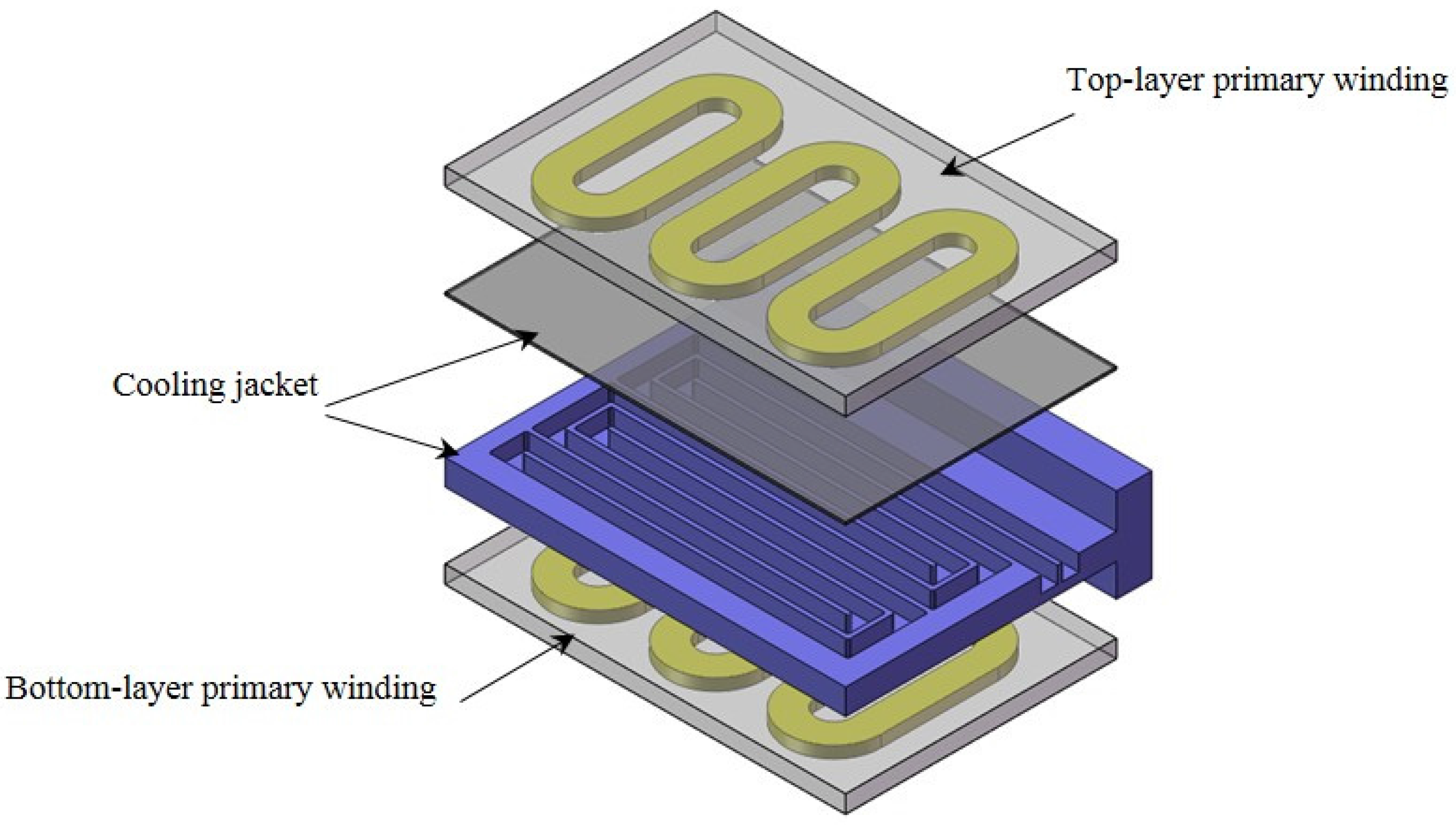
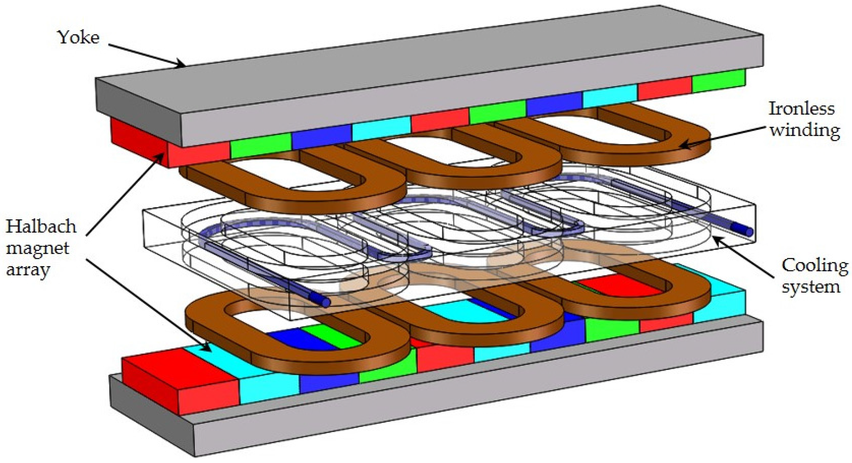
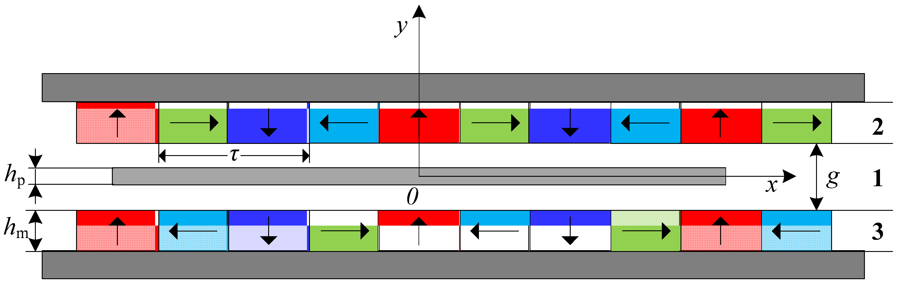
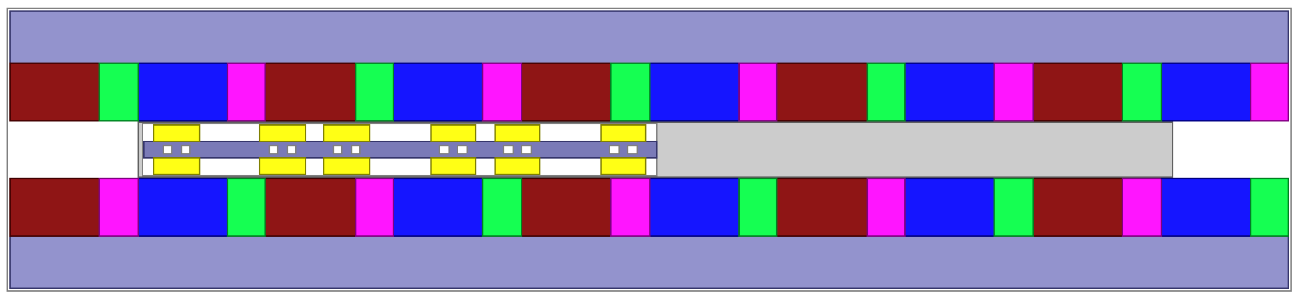
2. Topology of the Novel Ironless LSM with Cooling System

The ironless permanent magnet linear synchronous motor investigated in this paper is shown in Figure 1. This ironless PMLSM consists of a mover with ironless winding and a stator with U-shaped yoke with a face-to-face Halbach magnet array mounted on it. A permanent magnet Halbach array is used to establish strong and sinusoidal magnetic field. Similar to permanent magnet rotary motors, the thrust is generated by the interaction between permanent magnetic field and travelling magnetic field, while the synchronous speed of the motor is the same as the speed of the travelling magnetic field. The primary winding is divided into two layers, and the cooling system is located between the two layers. Water flows through the cooling jacket and the heat generated by the permanent magnet linear synchronous motor is taken away by the cooling water.

3. Magnetic Field Analysis and Calculation of the Eddy Current Braking Force

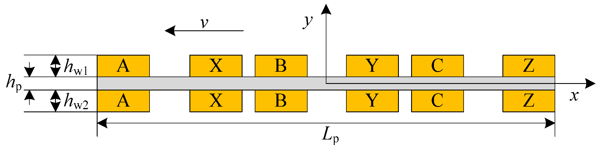
3.1. Magnetic Field Produced by the Halbach Magnet Array

Figure 2 shows the analytical model of the PMLSM for the magnetic field analysis. The sources of the permanent magnet array are expressed in the form of a Fourier series, so that higher order harmonics can be taken into consideration. As the doubled-sided linear motor has a symmetric structure along the y-axis, only one side is selected as the analysis region. To simplify, some assumptions are made, as follows [9,10,11,12]:
  • All regions are extended infinitely in the x-direction
  • Permanent magnets are periodically distributed along the x-axis
  • The permeability of the yoke is infinite and the permeability of the permanent magnet material is equal to the permeability of free space
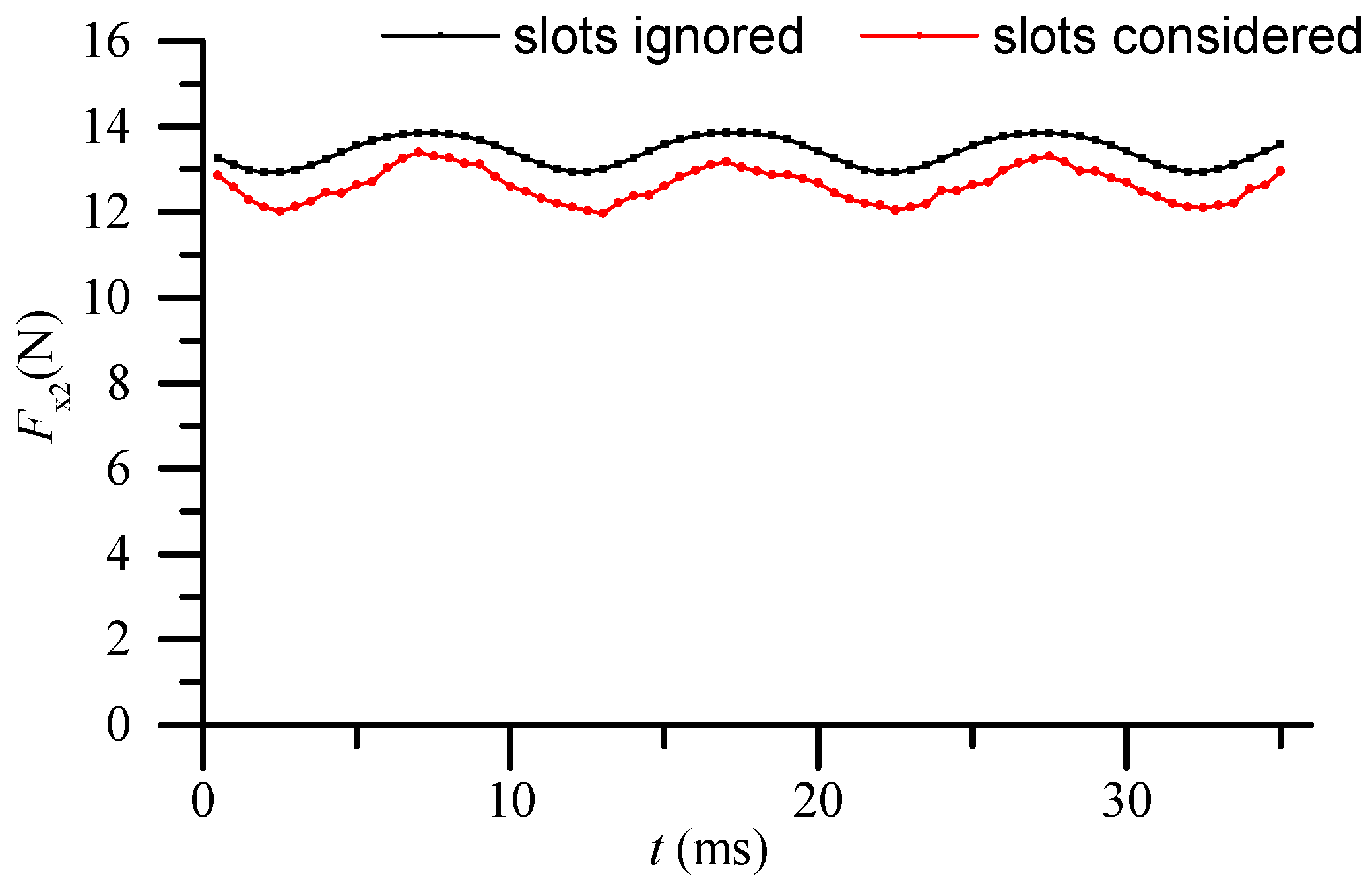
  • The effects of the slots inside the cooling jacket are ignored
If the transverse edge effects are temporarily ignored, i.e., the eddy currents are considered to flow only in the z-direction, the actual 3-D problem is then reduced to a 2-D one [13,14,15].
The analytical model is divided into three regions as shown in Figure 2. In region 1, the magnetic vector potential satisfies the Laplace equation, in region 2 and 3, the magnetic vector potential satisfies the Poisson equation.
{ 2 A z 1 x 2 + 2 A z 1 y 2 = 0 2 A z 2 x 2 + 2 A z 2 y 2 = μ 0 M x x 2 A z 3 x 2 + 2 A z 3 y 2 = μ 0 M x x
where J M = × M , Az is the z-axis component of the vector magnetic potential, JM is equivalent magnetizing current density.
{ M = M x i + M y j M x = n = 1 4 B r ( 2 n 1 ) π μ 0 cos ( 2 n 1 ) π α p 2 sin ( 2 n 1 ) π x τ M y = n = 1 4 B r ( 2 n 1 ) π μ 0 sin ( 2 n 1 ) π α p 2 cos ( 2 n 1 ) π x τ
Equation (1) satisfies the boundary conditions (3).
{ B y 1 | y = 1 2 g = B y 2 | y = 1 2 g H y 2 | y = 1 2 g H y 1 | y = 1 2 g = M x B y 1 | y = 1 2 g = B y 2 | y = 1 2 g H y 2 | y = 1 2 g H y 1 | y = 1 2 g = M x H y 2 | y = 1 2 g + h m = M x H y 2 | y = 1 2 g h m = M x
According to the boundary condition (3), Variable Separation Method is used to solve the differential equations in the regions. The magnetic fields induced by permanent magnets can be derived as follows. The correctness of the analytical calculation of the Halbach array field distribution has been verified in our previous work [15].
B y 1 = B ym cosh ( π τ y ) cos ( π τ x )
B ym = π τ { K [ K cosh ( π τ g 2 ) + T sinh ( π τ g 2 ) ] cosh [ π τ ( g 2 + h m ) ] sinh [ π τ ( g 2 + h m ) ] + K sinh ( π τ g 2 ) + T cosh
where g is the length of the air-gap, hm is the thickness of the magnet, and hp is the thickness of the cooling jacket.
{ K = 4 τ B r π 2 cos ( π α p 2 ) T = 4 τ B r π 2 sin ( π α p 2 )

3.2. The Eddy Current Density

As the demagnetization effect of the eddy current in the cooling jacket is ignored, Equation (4) can be regarded as the expression of the flux density in the cooling jacket. In Figure 2, the magnetic vector potential in the cooling jacket also satisfies the following equation
2 A z x 2 + 2 A z y 2 = j ω μ σ A z
where ω is the angular frequency, μ is the permeability of the cooling plate, σ is the conductivity of the cooling plate.
Transforming (6) to a time domain equation as follows
2 A z x 2 + 2 A z y 2 = μ σ A z t
At t = 0, the magnetic vector potential satisfies the following boundary conditions.
{ B y | y = 1 2 h p = B ym cosh ( π τ 1 2 h p ) cos ( π τ x ) B y | y = 1 2 h p = B ym cosh ( π τ 1 2 h p ) cos ( π τ x )
The general solution of (7) can be solved by Variable Separation Method as follows
A z = C 1 [ e α y sin ( ω t π τ x β y + θ 1 ) + e α y sin ( ω t π τ x + β y + θ 1 ) ]
where
{ α = γ cos φ β = γ sin φ γ 2 = ( π / τ ) 4 + ( ω μ σ ) 2 φ = 1 2 arctan ( ω μ σ ( π / τ ) 2 )
According to the boundary conditions (8), Variable Separation Method is applied to solving the Equation (7).
{ θ 1 = arctan ( tanh ( α h p 2 ) tan ( β h p 2 ) ) C 1 = B ym cosh ( π h p 2 τ ) π τ 2 cosh ( α h p ) + 2 cos ( β h p )
In the cooling jacket, the magnetic vector potential, magnetic field density, and eddy current density meet the following relationship
{ H x = 1 μ A z y H y = 1 μ A z x J z = H y x H x y
By substituting (9) into (11), the expression of the eddy current density can be written as
J z = 2 C 1 α β μ [ e α y cos ( ω t π τ x β y + θ 1 ) + e α y cos ( ω t π τ x + β y + θ 1 ) ]

3.3. The Eddy Current Braking Force

According to previous analysis, the normal flux density in the cooling plate can be written as
B y = C 1 m 1 [ e α y cos ( ω t π τ x β y + θ 1 ) + e α y cos ( ω t π τ x + β y + θ 1 ) ]
At any time, differential form of the tangential eddy current braking force is
d F x 2 = B y J z l w d x d y
where lw is the horizontal width of the cooling plate.
Figure 3 shows the analytical model of eddy current braking force. From t = 0, the expression of the eddy current braking force induced in the cooling jacket can be written as follows
F x 2 = d F x 2 d x d y = 2 C 1 2 π α β l w μ 0 τ L p 2 v t L p 2 v t h p 2 h p 2 [ e α y cos ( π τ x β y + θ 1 ) + e α y cos ( π τ x + β y + θ 1 ) ] 2 d x d y = 2 C 1 2 π l w μ 0 τ [ β sinh ( α h p ) + α sin ( β h p ) ] L p + C 1 2 C 2 α β l w μ 0 sin ( π τ L p ) sin ( 2 ω t + θ 2 )
where
{ C 2 = C 3 2 + 4 h p 2 + 2 C 3 sin ( θ 3 φ ) θ 2 = 2 θ 1 + arctan C 3 cos ( θ 3 φ ) C 3 cos ( θ 3 φ ) + 2 h p C 3 = 2 cosh ( 2 α h p ) 2 cos ( 2 β h p ) / γ θ 3 = arctan ( coth ( α h p ) tan ( β h p ) )
From Equation (15), it can be noticed that the eddy current braking force includes two parts, the constant component and the volatile component. The amplitude and fluctuation of the eddy current braking force are determined by the size of the cooling jacket and the motor’s speed.

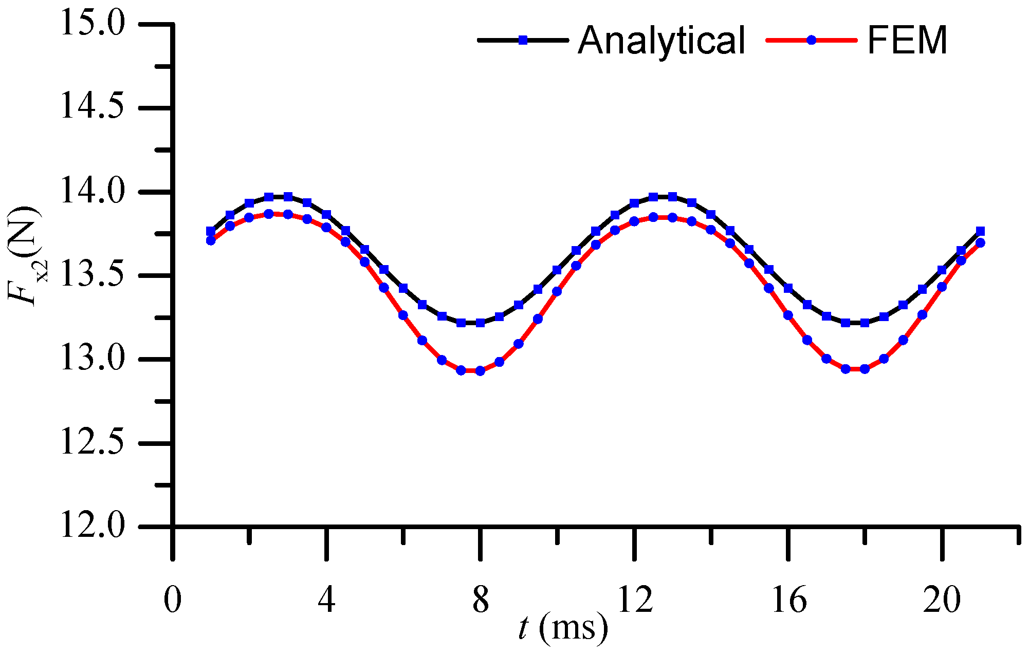
4. Simulation Verification

4.1. Simulation Verification

A 2-D finite element simulation model of the ironless linear synchronous motor with cooling system was established based on the Maxwell equations in Ansoft, as shown in Figure 4. By using FEM, the eddy current braking force induced in the cooling system was calculated and compared with the analytical results. Table 1 shows parameters dimension of the finite element simulation model of the PMLSM.
Figure 5 shows the comparison of the eddy current braking force Fx2 of the ironless linear synchronous motor with cooling system between theoretical analysis and FEM simulation. As the effects of high order harmonics and the end effects are taken into consideration in the simulation model, the force ripple of the simulation result is larger than the analytical result. As a whole, the analytical results are in good agreement with the simulation results.
Figure 6 shows the structure of the cooling jacket with slots. Figure 7 shows the comparison of the eddy current braking force Fx2 of the ironless linear synchronous motor with cooling system between the slots are ignored and considered. The two curves are basically consistent with each other. When the slots on the cooling jacket are considered, it can be observed from Figure 7 that the average of the eddy current braking force decreases, and the fluctuation amplitude increases. In Figure 7, the maximum error between the two curves is about 0.8 N, only 6% of the average of the eddy current braking force, within acceptable limits.

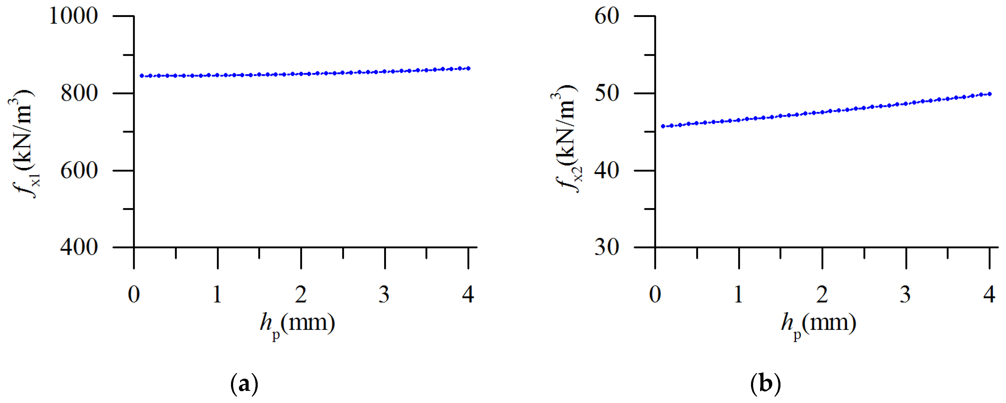
4.2. Influence of the Motor Parameters on the Eddy Current Braking Force

According to Equation (15), it can be observed that the eddy current braking force is consists of the constant component (Fx21) and the volatile component (Fx22). The two-eddy current braking force densities are defined as Equations (16) and (17), respectively.
f x 1 = F x 21 h p L p l w
f x 2 = F x 22 h p L p l w
The force density fx1 reflects the size of the eddy current brake force and the force density fx2 reflects the fluctuation of the eddy current brake force.
It can be observed from Figure 8a, fx1 increases slowly along with the increase of hp. As the change of hp is limited, fx1 basic remain the same value as the change of hp. Therefore, the eddy current brake force density can be seen as constant along with the change of hp. By contrast, fx2 increases linearly along with the increase of hp as shown in Figure 8b. In order to reduce the eddy current brake force's volatility, the thickness of the cooling jacket should be reduced. It should be pointed out that, the total braking force mainly comes from the electromagnetic braking force, while eddy current only contributes a fraction to the total braking force. Improving the thickness of the cooling jacket can strengthen primary motor cooling capacity and increase the current value of the primary winding, thus increasing the electromagnetic braking force as well as the total braking force. Therefore, the selection of the thickness of the cooling jacket should be given priority over all the other factors.
From Equation (15), it can be observed that the volatile component of the eddy current brake force associated with the value of Lp/τ. It can be observed from Figure 9a, fx1 remains relatively constant no matter what the value of Lp/τ is. However, in Figure 9b, fx2 attenuates according to the sine law along with the increase of Lp/τ, and reaches the minimum when the length of the cooling jacket equals the integer times the pole pitch. Consequently, for the design of the motor, the length of the cooling jacket should be the integer times the pole pitch.

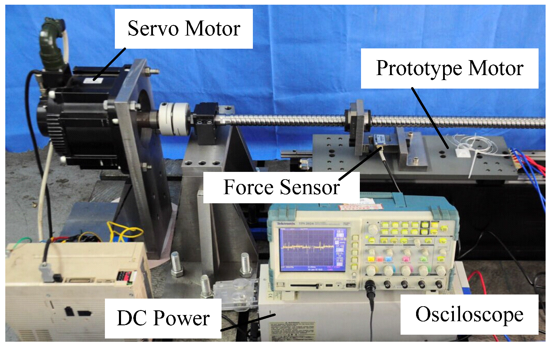
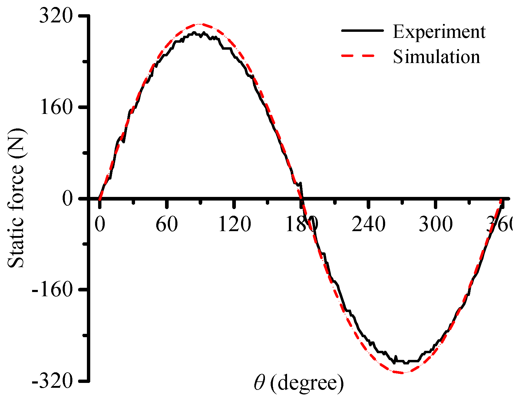
5. Prototype and Experiments

An ironless linear synchronous motor with a cooling system was designed and produced in laboratory based on the previous study, as shown in Figure 10. The test platform of the LSM (linear synchronous motor) is established with the prototype, as shown in Figure 11. Some experiments were carried out with the prototype and the experiment results are validated by finite element analyzed results.
By using the prototype, the no-load back-EMF (electromotive force) waveform of the PMLSM was measured, as shown in Figure 12. It can be observed that the three phase no-load back-EMF waveforms were of good sinusoidal shape. Figure 13 shows the comparison of the no-load back-EMF waveform between simulation result and experiment result. It can be observed from Figure 13 that the two curves are consistent with each other and the difference between the peak values of the two curves is about 5% of the average of peak value, within acceptable limits.
Figure 14 shows the comparison of the static thrust waveform between simulation result and experiment result. It can be observed from Figure 14 that the peak value of the simulation result is 202.9 N and the peak value of the experiment result is 194.6 N, so the difference between the two curves is 8.3 N, about 4% of the average. The error is mainly caused by factors such as the actual machining accuracy, the actual installation precision, and so on.

6. Conclusions

In this work, an ironless linear synchronous motor with a cooling system was proposed. The topology of the ironless linear synchronous motor with a cooling system was first introduced. The expression of the flux density in the cooling jacket was solved analytically and the eddy current braking force induced in the cooling system was investigated and validated by finite element method. The influence of the motor parameters on the eddy current braking force was investigated. At last, a prototype was designed and manufactured, and some characteristics of the linear synchronous motor were measured and validated. The feasibility of the design has been proven by the comparison of the characteristics of the linear synchronous motor between simulation and experiments. The thrust ripple and thermal characterization of the prototype will be investigated in future work.

Acknowledgments

This work was supported in part by the China Postdoctoral Science Foundation Funded Project (2015M80262), in part by the State Key Program of National Natural Science of China under Grant (51537002), in part by the National Natural Science of China (51607044), in part by the Natural Science Foundation of Heilongjiang Province (E2016035), and in part by “the Fundamental Research Funds for the Central Universities” (Grant No. HIT. NSRIF. 2017010).

Author Contributions

Lu Zhang, Baoquan Kou, and Yusheng Chen conceived and designed the experiments; Yusheng Chen and Yinxi Jin performed the experiments; Yinxi Jin and Yanjie Liu analyzed the data; Yanjie Liu contributed reagents/materials/analysis tools; Lu Zhang wrote the paper.

Conflicts of Interest

The authors declare no conflict of interest.

References

  1. Sun, P.; Zhou, H. Air-gap magnetic field design optimization for U-shaped ironless permanent magnet linear synchronous motors. In Proceedings of the International Conference on Electrical Machines & Systems, Wuhan, China, 17–20 October 2008; pp. 123–138.
  2. Park, K.S.; Choi, J.; Park, Y.P.; Park, N.C. Thermal deformation of thermally assisted magnetic recording head in binary gas mixture at various temperatures. IEEE Trans. Magn. 2013, 49, 2671–2676. [Google Scholar] [CrossRef]
  3. Lu, Q.; Zhang, X.; Chen, Y.; Huang, X.; Ye, Y.; Zhu, Z.Q. Modeling and investigation of thermal characteristics of a water-cooled permanent-magnet linear motor. IEEE Trans. Ind. Appl. 2015, 51, 2086–2096. [Google Scholar] [CrossRef]
  4. Boglietti, A.; Cavagnino, A.; Staton, D.; Shanel, M.; Mueller, M.; Mejuto, C. Evolution and modern approaches for thermal analysis of electrical machines. IEEE Trans. Ind. Electron. 2009, 56, 871–882. [Google Scholar] [CrossRef]
  5. Chen, Y.; Yao, Y.; Lu, Q.; Ye, Y.; Huang, X. Electromagnetic and thermal coupling analysis of a water-cooled double-sided permanent magnet linear synchronous motor. In Proceedings of the International Conference on Electrical Machines and Systems IEEE, Pattaya, Thailand, 25–28 October 2015; pp. 1136–1140.
  6. Bracikowski, N.; Hecquet, M.; Brochet, P.; Shirinskii, S.V. Multiphysics modeling of a permanent magnet synchronous machine by using lumped models. IEEE Trans. Ind. Electron. 2012, 59, 2426–2436. [Google Scholar] [CrossRef]
  7. Jungreuthmayer, C.; Bäuml, T.; Winter, O.; Ganchev, M.; Kapeller, H.; Haumer, A.; Kral, C. A detailed heat and fluid flow analysis of an internal permanent magnet synchronous machine by means of computational fluid dynamics. IEEE Trans. Ind. Electron. 2012, 59, 4568–4578. [Google Scholar] [CrossRef]
  8. Jankowski, T.A.; Prenger, F.C.; Hill, D.D.; O’Bryan, S.R.; Sheth, K.K.; Brookbank, E.B.; Hunt, D.F.A.; Orrego, Y.A. Development and validation of a thermal model for electric induction motors. IEEE Trans. Ind. Electron. 2010, 57, 4043–4054. [Google Scholar] [CrossRef]
  9. Kazan, E.; Onat, A. Modeling of air core permanent-magnet linear motors with a simplified nonlinear magnetic analysis. IEEE Trans. Magn. 2011, 47, 1753–1762. [Google Scholar] [CrossRef]
  10. Tavana, N.R.; Shoulaie, A. Minimizing thrust fluctuation in linear permanent magnet synchronous motor with Halbach array. In Proceedings of the 1st Power Electronic & Drive Systems & Technologies Conference, Tehran, Iran, 17–18 Feburary 2010; pp. 302–306.
  11. Kang, G.H.; Hong, J.P.; Kim, G.T. A novel design of an air-core type permanent magnet linear brushless motor by space harmonics field analysis. IEEE Trans. Magn. 2001, 37, 3732–3736. [Google Scholar] [CrossRef]
  12. Chen, Y.S. Research on Ironless Linear Permanent Magnet Synchronous Loading Motor and Cooling System. Master’s Dissertation, Harbin Institute of Technology, Harbin, China, 2012. [Google Scholar]
  13. Kou, B.; Zhang, L.; Li, L. Modeling and analysis of a novel composite-current driven synchronous permanent magnet planar motor. In Proceedings of the 6th International Conference on Electrical Machines and Systems (ICEMS 2011), Beijing, China, 1–4 August 2011.
  14. Wang, J.; Lin, H.; Fang, S.; Huang, Y. A general analytical model of permanent magnet eddy current couplings. IEEE Trans. Magn. 2014, 50, 8000109. [Google Scholar] [CrossRef]
  15. Zhang, L.; Kou, B.; Xing, F.; Zhao, B. Characteristic analysis of an ironless linear synchronous motor with novel Halbach magnet array. In Proceedings of the 17th International Symposium on Electromagnetic Launch Technology, San Diego, CA, USA, 1–5 July 2014.
Figure 1. The novel ironless linear synchronous motor with cooling system.
Applsci 06 00422 g001
Figure 2. The analytical model of the permanent magnet linear synchronous motors (PMLSM).
Applsci 06 00422 g002
Figure 3. The analytical model of eddy current braking force.
Applsci 06 00422 g003
Figure 4. The finite element simulation model of the PMLSM.
Applsci 06 00422 g004
Figure 5. Comparison of eddy current braking force Fx2 between analytical and simulation.
Applsci 06 00422 g005
Figure 6. The cooling jacket with slots.
Applsci 06 00422 g006
Figure 7. Comparison of eddy current braking force Fx2 between slots ignored and slots considered.
Applsci 06 00422 g007
Figure 8. The curves of the two-eddy current braking force density along with the change of hp. (a) The curve of fx1 along with the change of hp; (b) The curve of fx2 along with the change of hp.
Applsci 06 00422 g008
Figure 9. The curves of the two-eddy current braking force density along with the change of Lp/τ. (a) The curve of fx1 along with the change of Lp/τ; (b) The curve of fx2 along with the change of Lp/τ.
Applsci 06 00422 g009
Figure 10. Photos of the prototype. (a) The coils and cooling jacket; (b) The stator; (c) The prototype motor.
Applsci 06 00422 g010
Figure 11. The test platform of the LSM.
Applsci 06 00422 g011
Figure 12. The measured no-load back-EMF waveform.
Applsci 06 00422 g012
Figure 13. Comparison of the no-load back-EMF waveform between the simulation result and experiment result.
Applsci 06 00422 g013
Figure 14. Comparison of the static thrust waveform between simulation result and experiment result.
Applsci 06 00422 g014
Table 1. Parameters dimension of the finite element simulation model of the PMLSM.
ParameterSymbolValueUnit
length of air-gapg10.5mm
pole pitchτ24mm
lateral width of the cooling jacketlw80mm
amplitude values of fundamental harmonicBym0.8T
thickness of the cooling jackethp2mm
length of the cooling jacketLp100mm
thickness of the top-layer coilhw13.5mm
thickness of the under-layer coilhw23.5mm

