Article

Dominant Channel Occupancy for Wi-Fi Backscatter Uplink in Industrial Internet of Things

1
Department of Convergence Software, Hallym University, 1 Hallymdaehak-gil, Chuncheon-si, Gangwon-do 24252, South Korea
2
Network Convergence Research Center, Korea Electronics Technology Institute, 11 World Cup buk-ro 54-gil, Mapo-gu, Seoul 03924, South Korea
*
Author to whom correspondence should be addressed.
Appl. Sci. 2016, 6(12), 427; https://doi.org/10.3390/app6120427
Submission received: 9 October 2016 / Revised: 23 November 2016 / Accepted: 8 December 2016 / Published: 13 December 2016

Abstract

:
This paper presents a dominant channel occupancy (DCO) mechanism for the Wi-Fi backscatter uplink in the industrial Internet of things (IIoT). The DCO provides high-priority channel access and reliable burst transmission to the Wi-Fi backscatter devices, thereby enabling the Wi-Fi backscatter tag to deliver its tag information to the Wi-Fi reader without interference from neighboring legacy Wi-Fi devices to guarantee the timeliness and reliability of the IIoT system. For the former, we consider three types of medium access control (MAC) configurations: “carrier sense multiple access with collision avoidance (CSMA/CA) starting with short inter-frame space (SIFS)”, “freezing of the backoff period”, and “reduced CWmin.” In addition, the DCO uses the SIFS between burst packets to guarantee reliable burst transmission. To verify the effectiveness of DCO and determine a proper value for MAC parameters, we conduct experimental simulations under IEEE 802.11n PHY/MAC environments. The simulation results show that the reduced CWmin has the most significant effect on the channel occupancy. The Wi-Fi backscatter devices achieve much higher throughput than the separate cases when two or more configurations are used simultaneously. Moreover, the results exhibit that the use of SIFS between consecutive packets supports reliable burst transmission regardless of the transmission of the legacy Wi-Fi devices in the vicinity.

1. Introduction

Recently, Wi-Fi backscatter has been considered as one of the emerging communication technologies that may help realize the industrial Internet of things (IIoT), which can improve the connectivity, efficiency, and scalability of smart machines in both enterprises’ manufacturing processes and supply chain monitoring and management systems [1,2,3,4,5]. Wi-Fi backscatter uses radio frequency (RF) signals as a power source and reuses the existing Wi-Fi infrastructure to provide RF-powered devices with Internet connectivity. Therefore, it allows billions of Wi-Fi devices to connect to the Internet without charging or swapping batteries. The Wi-Fi backscatter consists of two types of communication: uplink communication and downlink communication. In uplink communication, the RF-powered device transmits its tag information to the Wi-Fi device, while the Wi-Fi device transmits data to the RF-powered device via downlink communication [6]. In particular, uplink communication is important for IIoT, since most IIoT applications aim to provide monitoring services using a number of physical sensors, which generate a huge amount of uplink-centric traffic [7,8].
However, the uplink communication of the existing Wi-Fi backscatter is easily interfered with by the transmissions of legacy Wi-Fi devices in the vicinity, since it commonly uses a carrier sense multiple access with collision avoidance (CSMA/CA) mechanism, as defined in the Wi-Fi standards [9,10,11,12]. Thus, it is difficult to guarantee timeliness and reliability, which are essential system requirements of the IIoT. The existing Wi-Fi backscatter cannot satisfy the strict delay constraint of the IIoT because of the long channel access delay caused by CSMA/CA operations and suffers from frequent packet losses and data corruptions. This is because the interferences of the neighboring legacy Wi-Fi devices make it difficult to guarantee consecutive transmissions of the Wi-Fi backscatter tag (i.e., RF-powered device). Note that Wi-Fi backscatter tags only transmit one bit of their own tag information according to whether they are reflecting the Wi-Fi signal.
Davenport et al. [13] developed a special type of shield, called a comb reflection frequency selective surface (CR-FSS) that can be installed on a wall to physically prevent interference between Wi-Fi access points (APs). However, CR-FSS cannot prevent interference between Wi-Fi APs placed in open spaces. Li et al. [14] presented a frame length and charging time adaptation in computational radio frequency identification (CRFID) backscatter communication, for which CRFID devices would use a dedicated link to communicate with each other. The use of a dedicated link might help prevent interference, but it cannot be adopted in the case of a Wi-Fi backscatter uplink where a number of Wi-Fi backscatter tags share a common channel through which they deliver their tag information.
It is strongly necessary to design a new medium access control (MAC) protocol for dedicated use in the Wi-Fi backscatter uplink to address the interference problem in Wi-Fi backscatter uplink communication, since the MAC protocol decides which device is used, and both when and how long it occupies the wireless channel when a number of network devices are trying to transmit packets simultaneously [15,16]. Kellogg et al. [6] and Bharadia et al. [17] developed dedicated MAC protocols for the downlink communication of Wi-Fi backscatter, which commonly use CTS-to-self packets to prevent interference with the neighboring legacy Wi-Fi devices. The CTS-to-self packet is used to set the network allocation vector (NAV) for neighboring legacy Wi-Fi devices to defer their transmissions by up to 32 ms, which is insufficient to deliver uplink-centric traffic from the Wi-Fi backscatter tag in IIoT applications. Specifically, the Wi-Fi reader should use multiple channel measurements to decode each bit transmitted by the Wi-Fi backscatter tag in the Wi-Fi backscatter uplink, due to the noise of the environment. Moreover, successive transmissions of multiple CTS-to-self packets are not available due to CSMA/CA operations, thus it cannot be a suitable solution to the interference problem.
Several studies have tried to differentiate Wi-Fi device channel access through MAC parameter configurations. Talla et al. [18] proposed a PoWiFi system that tunes the contention window (i.e., CWmin and CWmax) to provide high-priority channel access. However, it only considers one power packet transmission; thus, it suffers from long channel access delays caused by CSMA/CA operations when a series of packets are transmitted to a sensor device. Furthermore, it only tunes the CWmin and CWmax, and such consideration cannot provide dominant priority channel access to Wi-Fi backscatter devices (i.e., Wi-Fi readers and Wi-Fi backscatter tags) while also supporting their burst transmissions. In [19], Scalia et al. proposed a dynamic MAC parameter configuration approach based on the IEEE 802.11e standard to maximize network throughput. It uses different arbitration inter-frame space (AIFS) instead of the distributed inter-frame space (DIFS) and different CWmin depending on the network congestion status; however, it cannot support Wi-Fi backscatter devices’ burst transmissions.
In this paper, we propose a dominant channel occupancy (DCO) mechanism for the Wi-Fi backscatter uplink that provides high-priority channel access and reliable burst transmission to Wi-Fi backscatter devices for guaranteeing the timeliness and reliability of the IIoT. The DCO enables the Wi-Fi backscatter tag to deliver its physical sensor data (i.e., tag information) to the Wi-Fi reader without interference from neighboring legacy Wi-Fi devices. In DCO, for high-priority channel access of Wi-Fi backscatter uplink, we consider the following three types of MAC configurations: (1) CSMA/CA starting with short inter-frame space (SIFS); (2) freezing of the backoff period; and (3) reduced CWmin. On the other hand, the CSMA/CA operation of legacy Wi-Fi: (1) uses a DIFS, not a SIFS; (2) increases the backoff period twice when collision occurs; and (3) uses a fixed CWmin. Furthermore, we employ SIFS between consecutive packets instead of CSMA/CA to guarantee reliable burst transmission, which means the transmission of a series of same-size packets. The experimental simulations are conducted to verify the effectiveness of the DCO and determine the proper values of the MAC parameters. Specifically, we investigate the channel occupancy of Wi-Fi backscatter devices by comparing the throughput between Wi-Fi backscatter and legacy Wi-Fi devices. The simulations are performed under IEEE 802.11n PHY/MAC environments [20], and both separate and composite cases are observed to check the impacts of each configuration. The simulation results show that the DCO can provide high-priority channel access and dominant channel occupancy to the Wi-Fi backscatter devices in the shared wireless channel. In particular, the reduced CWmin has the most significant effect on throughput performance. When two or more MAC configurations are used simultaneously, the Wi-Fi backscatter devices achieve much higher throughput than the separate cases. The results also show that the Wi-Fi backscatter devices can dominantly occupy the shared wireless channel for burst transmission without any interruption by using the SIFS between consecutive packets. The contributions of our work can be summarized as follows.
  • We propose a new MAC layer solution for the Wi-Fi backscatter uplink, which is essential in most IIoT applications. As mentioned above, the existing Wi-Fi backscatter approach mainly focuses on downlink communication, but most IIoT monitoring applications make little use of their downlink and only require a very small bandwidth (e.g., a few kilobits per second) for command transmissions if utilized.
  • The DCO can be applied to all Wi-Fi standards including IEEE 802.11b/g/n that use CSMA/CA operations. In contrast, the existing Wi-Fi backscatter approach utilizes CTS-to-self packets to deal with interference, which is only supported by the Wi-Fi standards released after IEEE 802.11g. Thus, many devices that only conform to IEEE 802.11b may cause interference under the existing approach.
  • The DCO guarantees reliable burst transmission for Wi-Fi backscatter devices without exchanging additional control packets such as CTS-to-self, regardless of the amount of tag information and number of channel measurements. This is clearly distinguished from the CTS-to-self manner of having a time limit of up to 32 ms.
The rest of this paper is organized as follows. Section 2 provides an overview of Wi-Fi backscatter uplink communication. Section 3 presents the detailed operation of the DCO. The experimental simulation is described in Section 4. Finally, we conclude our study in Section 5.

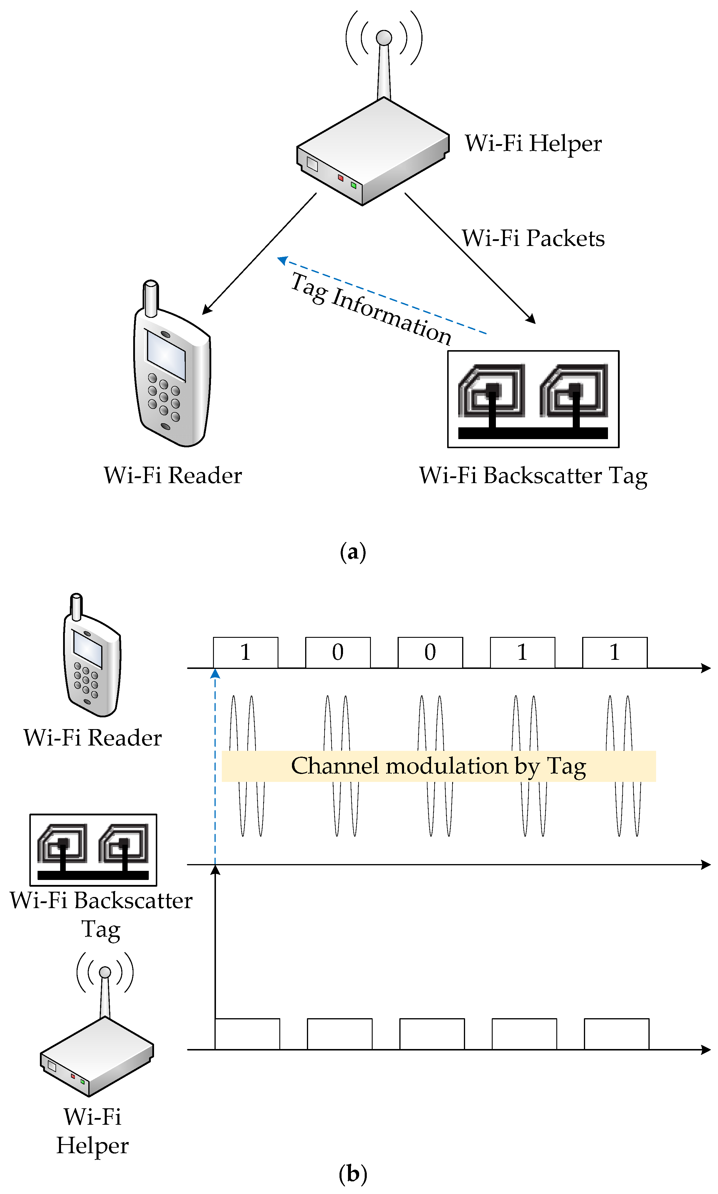
2. Wi-Fi Backscatter Uplink Communication

Figure 1 illustrates the architecture and operation of Wi-Fi backscatter uplink communication. As shown in Figure 1a, the Wi-Fi backscatter includes three types of devices: the Wi-Fi reader, Wi-Fi helper, and Wi-Fi backscatter tag, which are the mobile device, Wi-Fi AP, and RF-powered device, respectively. For uplink communication, the Wi-Fi backscatter tag transmits its tag information to a Wi-Fi reader by either reflecting or not reflecting a Wi-Fi helper signal. Figure 1b shows the operation of Wi-Fi backscatter uplink communication. The Wi-Fi helper consecutively transmits the same size of packets. Then, the Wi-Fi backscatter tag modulates these transmissions by either reflecting or not reflecting the signals. The Wi-Fi reader decodes the modulated transmissions by using the variation of received signal strength indicator (RSSI) or channel state information (CSI) [21,22]. Note that the reflected packets are decoded as “1” bits by the Wi-Fi reader or “0” bits [6]. As mentioned earlier, the existing Wi-Fi backscatter hardly ensures the consecutive packet transmissions of the Wi-Fi helper when multiple Wi-Fi devices (e.g., legacy Wi-Fi APs and clients) simultaneously transmit their packets in the vicinity, because the Wi-Fi helper should compete with other legacy Wi-Fi devices to access the channel by using CSMA/CA.

3. Design of the DCO

The DCO is designed to guarantee the timeliness and reliability of Wi-Fi backscatter uplink communication. To this end, the DCO provides four types of MAC configurations for the purpose of the high-priority channel access and reliable burst transmission of Wi-Fi backscatter devices. Three of them are used to support high-priority channel access, and one of them is used for reliable burst transmission. In the following subsections, we describe the design of the DCO in detail.

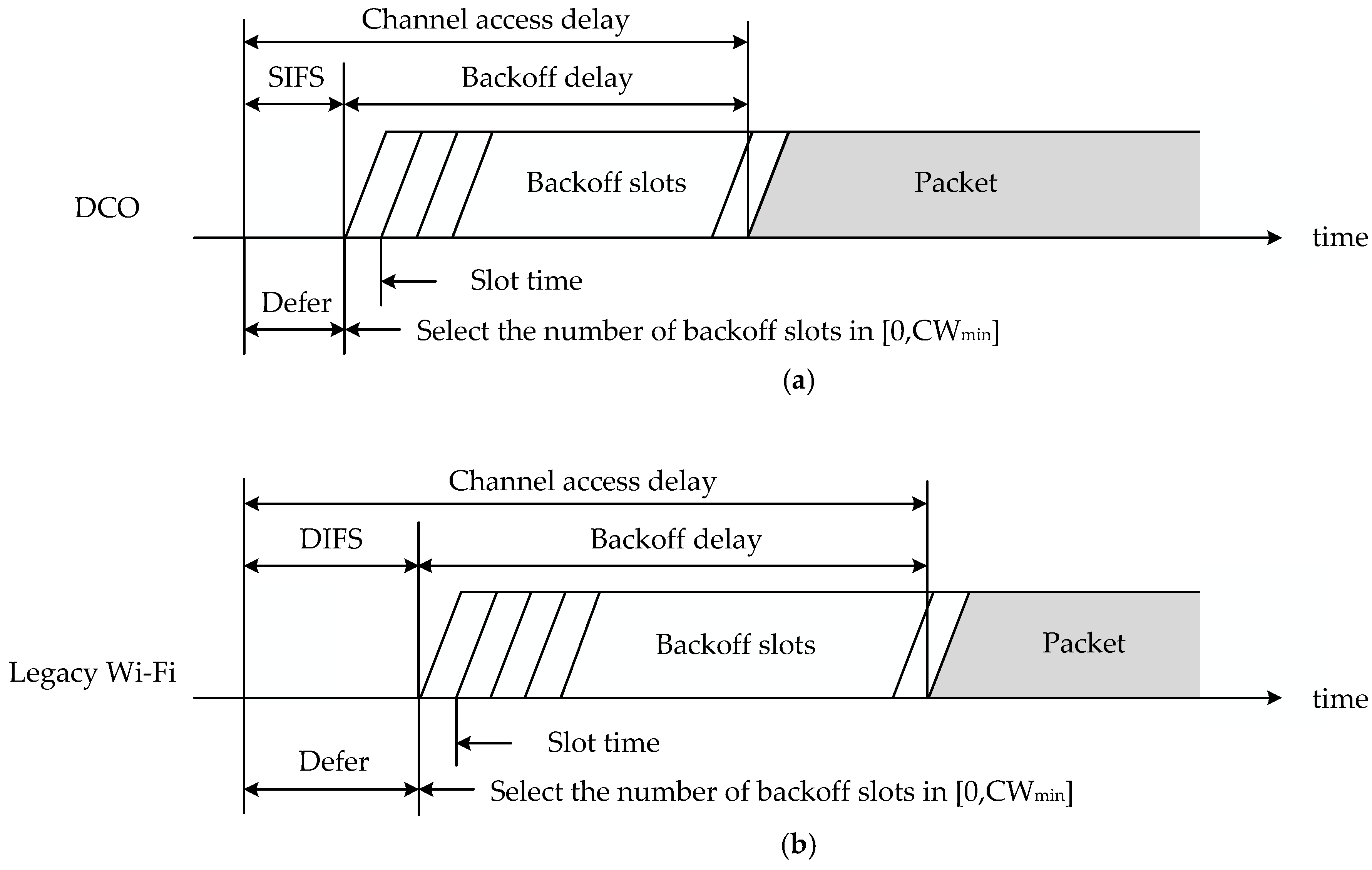
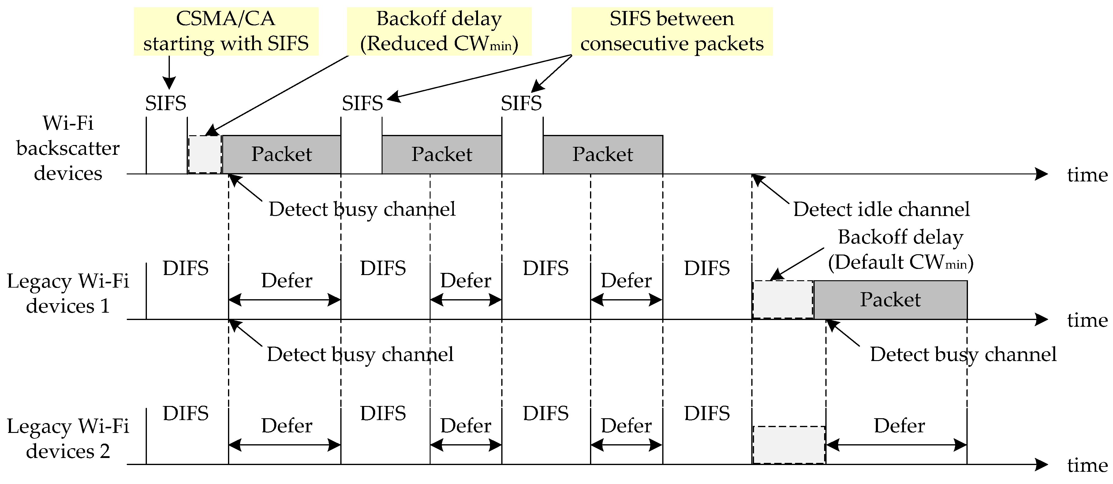
3.1. High-Priority Channel Access

The DCO guarantees the timeliness of Wi-Fi backscatter uplink communication by providing high-priority channel access to the Wi-Fi backscatter devices. For high-priority channel access, the DCO uses three types of MAC configurations: (1) CSMA/CA starting with SIFS; (2) freezing of the backoff period; and (3) reduced CWmin. Note that the CSMA/CA operation of legacy Wi-Fi devices: (1) uses a DIFS, not a SIFS; (2) increases the backoff period twice when collision occurs; and (3) uses a fixed CWmin. The first MAC configuration reduces the waiting time of the Wi-Fi backscatter devices spent at the beginning of CSMA/CA by replacing the DIFS with SIFS. Specifically, it reduces the waiting time by “2 × slot time”, since DIFS is calculated as “SIFS + 2 × slot time.” Consequently, Wi-Fi backscatter devices start the next step (i.e., the backoff procedure) earlier than the legacy Wi-Fi devices in the vicinity. The second configuration can reduce the backoff delay when collision occurs. After collision occurs, the DCO makes the Wi-Fi backscatter devices maintain the length of backoff period, given as [0, 2BE–1], where BE is the backoff exponent. The minimum and maximum BEs (i.e., MacMinBE and MacMaxBE, respectively) are pre-determined by the system, and 2MacMinBE–1 is equal to CWmin [23,24]. To maintain the length of the backoff period after collision, the DCO uses a fixed value of BE (i.e., MacMinBE) regardless of the collision. The freezing of the backoff period increases the probability that Wi-Fi backscatter devices will have fewer backoff slots than other legacy Wi-Fi devices. The last configuration can reduce the backoff delay for initial channel access by reducing the value of CWmin. The reduced CWmin decreases the maximum number of backoff slots for initial channel access. Considering that the number of backoff slots is randomly selected in [0, CWmin], the reduced CWmin makes the Wi-Fi backscatter devices have fewer backoff slots than legacy Wi-Fi devices for initial channel access.
Figure 2 shows a comparison of initial channel access between (Figure 2a) the DCO and (Figure 2b) legacy Wi-Fi. In the figure, the DCO defers the backoff procedure for SIFS, which is a shorter waiting time than that of legacy Wi-Fi devices. In addition, the DCO has shorter backoff delay than the legacy Wi-Fi because it uses the reduced CWmin. Since the channel-access delay of the DCO is shorter than that of the legacy Wi-Fi, it can provide high-priority channel access to Wi-Fi backscatter devices, which allows the Wi-Fi backscatter devices to transmit a packet earlier than others. The legacy Wi-Fi device defers its own transmission when it detects a busy channel via carrier sensing; thus, the high-priority channel access can guarantee the timeliness of the Wi-Fi backscatter devices regardless of the legacy Wi-Fi devices in the vicinity.

3.2. Reliable Burst Transmission

In Wi-Fi backscatter uplink communication, the Wi-Fi backscatter tag transmits its tag information comprised of multiple bits to the Wi-Fi reader by reflecting a series of packets, since one packet reflected by the Wi-Fi backscatter tag is decoded as one bit by the Wi-Fi reader. Accordingly, to guarantee the reliability of Wi-Fi backscatter uplink communication, the Wi-Fi backscatter devices should have the ability to transmit multiple packets without any interruption. In other words, reliable burst transmission is indispensable for guaranteeing the communication between Wi-Fi backscatter devices. For reliable burst transmission, the DCO uses SIFS between consecutive packets. Note that the legacy Wi-Fi uses the CSMA/CA mechanism whenever the packet is transmitted, which causes DIFS and backoff delay. The use of SIFS between burst packets can provide dominant channel occupancy to Wi-Fi backscatter devices, since it enables the Wi-Fi backscatter devices to start packet transmission before the legacy Wi-Fi devices perform carrier sensing (i.e., backoff). The legacy Wi-Fi devices defer their transmission until the end of the burst transmission of Wi-Fi backscatter devices upon detecting the busy channel through carrier sensing.
Figure 3 shows an operational example of the burst transmission of Wi-Fi backscatter devices running DCO. In the example, a pair of Wi-Fi backscatter devices and two pairs of neighboring legacy Wi-Fi devices are assumed. The Wi-Fi backscatter devices employ DCO and have three packets for burst transmission. On the other hand, the legacy Wi-Fi devices use the CSMA/CA mechanism and have one packet to transmit. In the figure, one of the Wi-Fi backscatter devices transmits the packet earlier than the others since it uses “CSMA/CA starting with SIFS” and “reduced CWmin”. Due to the transmission of the Wi-Fi backscatter devices, the legacy Wi-Fi devices detect a busy channel after DIFS and defer their transmission until the end of the transmission. After the successful transmission, the Wi-Fi backscatter devices and legacy Wi-Fi devices wait for SIFS and DIFS, respectively. Then, the Wi-Fi backscatter devices occupy the channel and the others defer their transmission again, since SIFS is shorter than DIFS. All the devices repeat their previous operation until the end of the burst transmission. In this example, all the packets of Wi-Fi backscatter can be transmitted successively without any interruption.
The real implementation of DCO additionally requires the low MAC development of the Wi-Fi helper, for which the developer can modify the MAC parameter configurations within the device driver source code of the embedded operating system. Note that current Wi-Fi open source device drivers such as OpenWrt, DD-WRT, Tomato, MadWifi are available for the hands-on development of DCO [25,26,27,28].

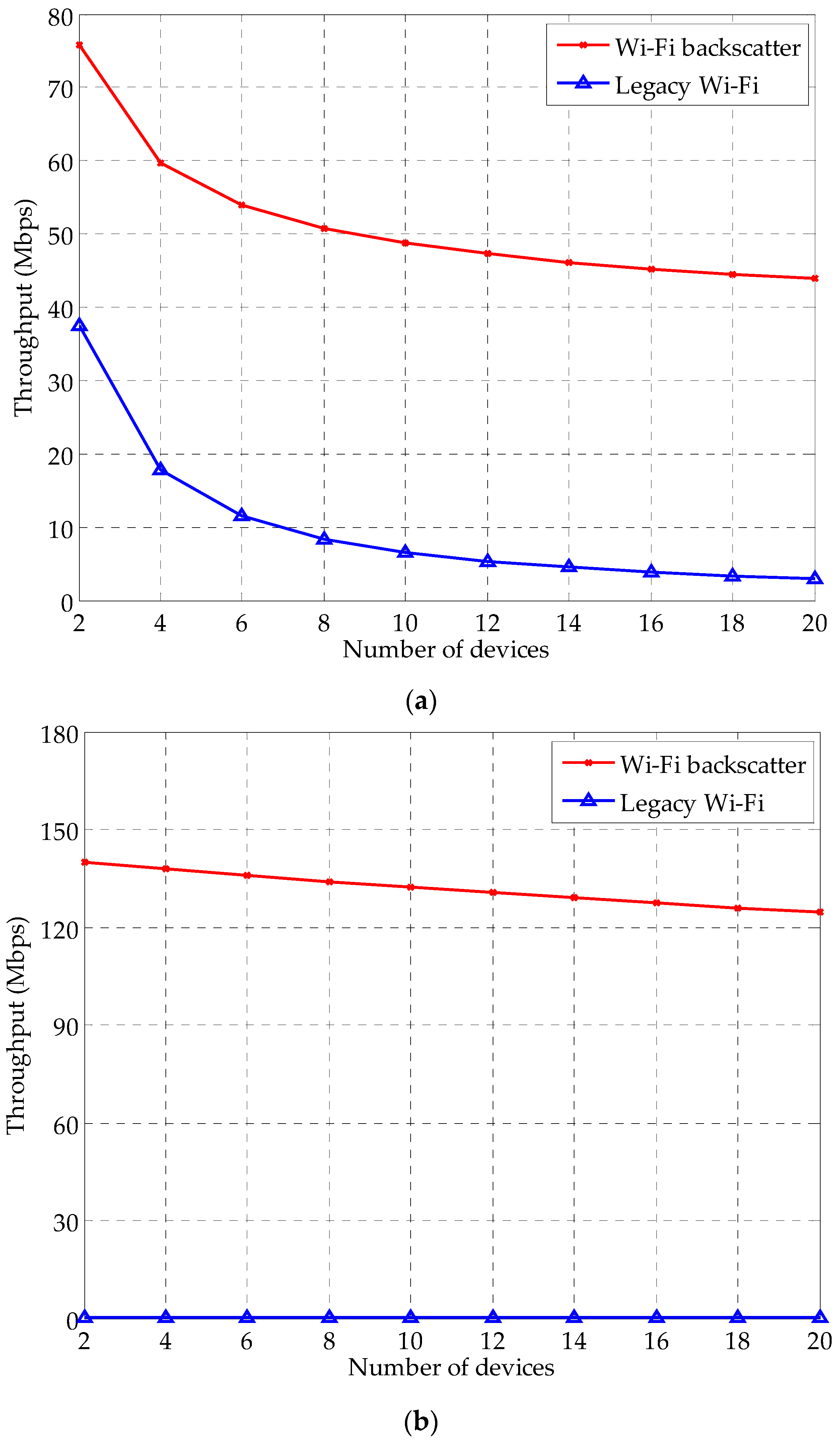
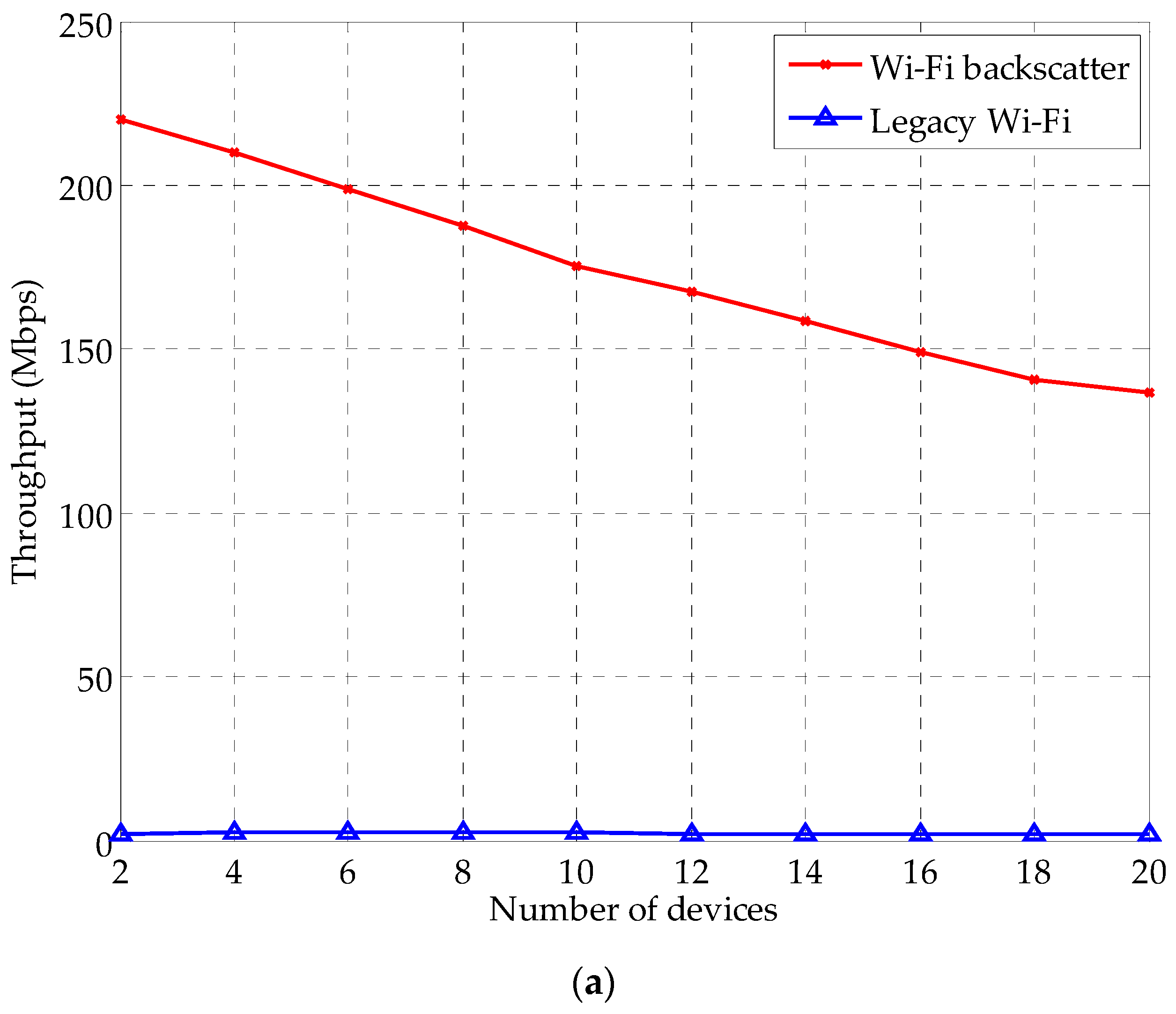
4. Performance Evaluation

In this section, we present the effectiveness of the DCO and determine the proper values of MAC parameters by conducting experimental simulations. In the simulation, MAC configurations are employed for the Wi-Fi backscatter devices only. We compare the throughput performance between the Wi-Fi backscatter devices and the legacy Wi-Fi devices to observe their channel occupancy variations. In the following subsections, we describe the simulation setup and discuss the results of the simulation in detail.

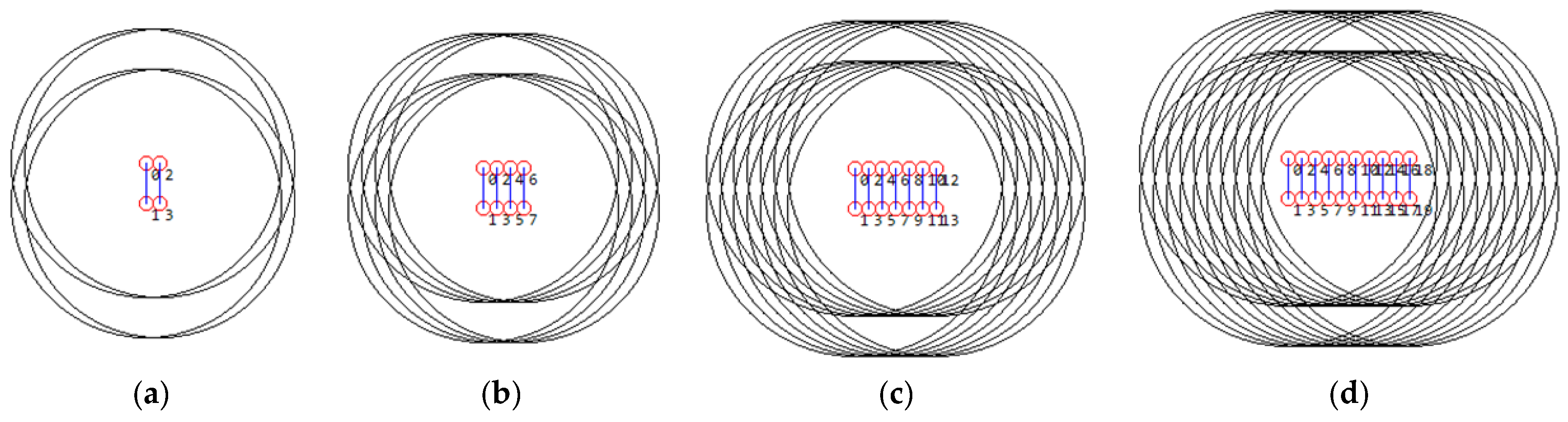
4.1. Simulation Setup

Figure 4 shows examples of the network topology with different numbers of devices. All devices are deployed in a 100 × 100 m2 region and have the same interference range. We consider a pair of devices (i.e., Tx and Rx devices) per transmission and set the Tx devices to transmit the packets consecutively. Multiple pairs of devices are deployed in the simulation region; one of the pairs is set to the Wi-Fi backscatter devices, and others are set to the legacy Wi-Fi devices. Considering the architecture of Wi-Fi backscatter uplink communication in Section 2, the Tx device of a pair of Wi-Fi backscatter devices should be a Wi-Fi helper. Therefore, we investigate the channel occupancy of Wi-Fi backscatter devices in the simulation by measuring the throughput of the Wi-Fi helper under IEEE 802.11n PHY/MAC environments. The simulation is repeated 30 times. The simulation parameters are listed in Table 1 in detail.

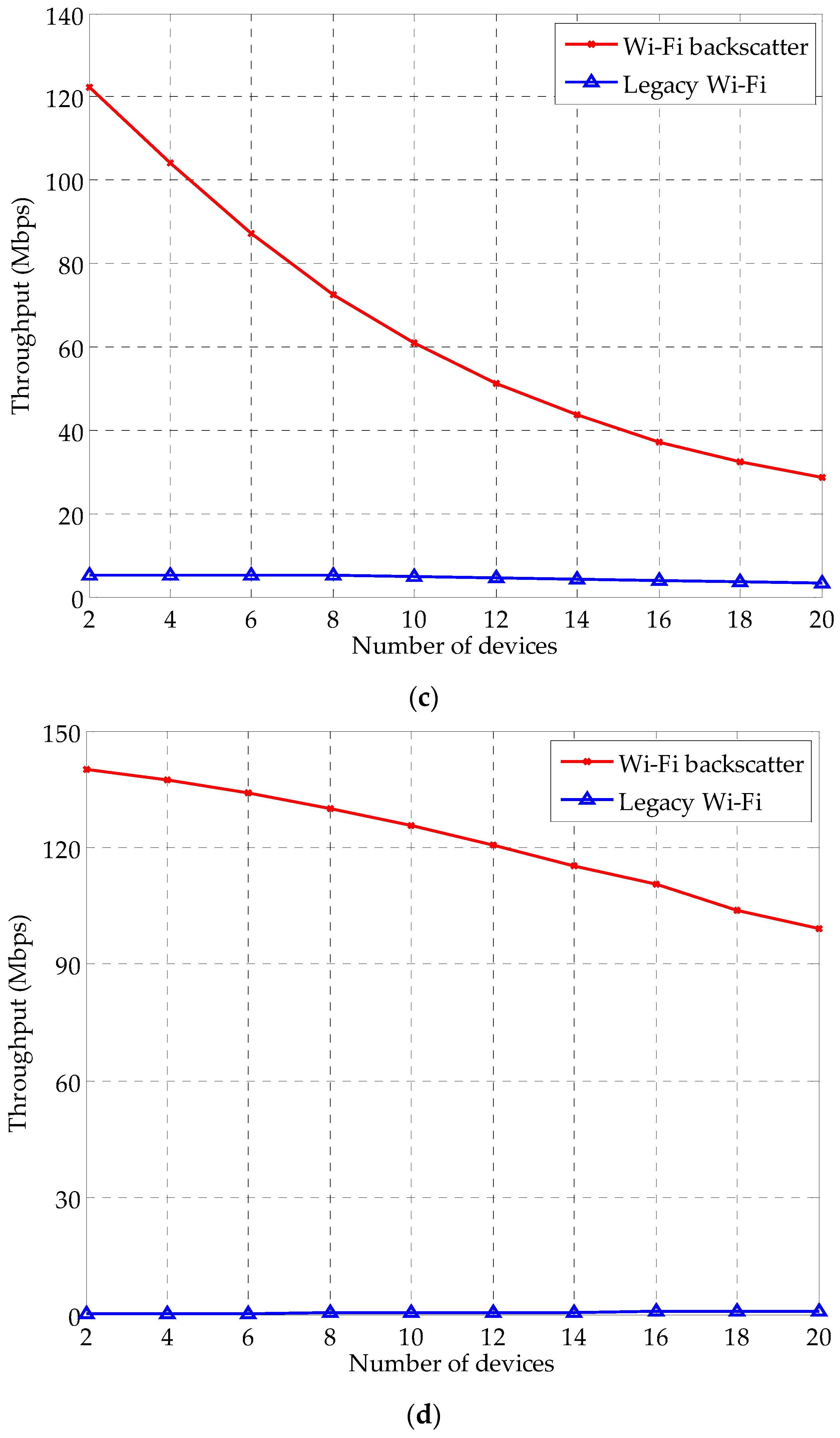
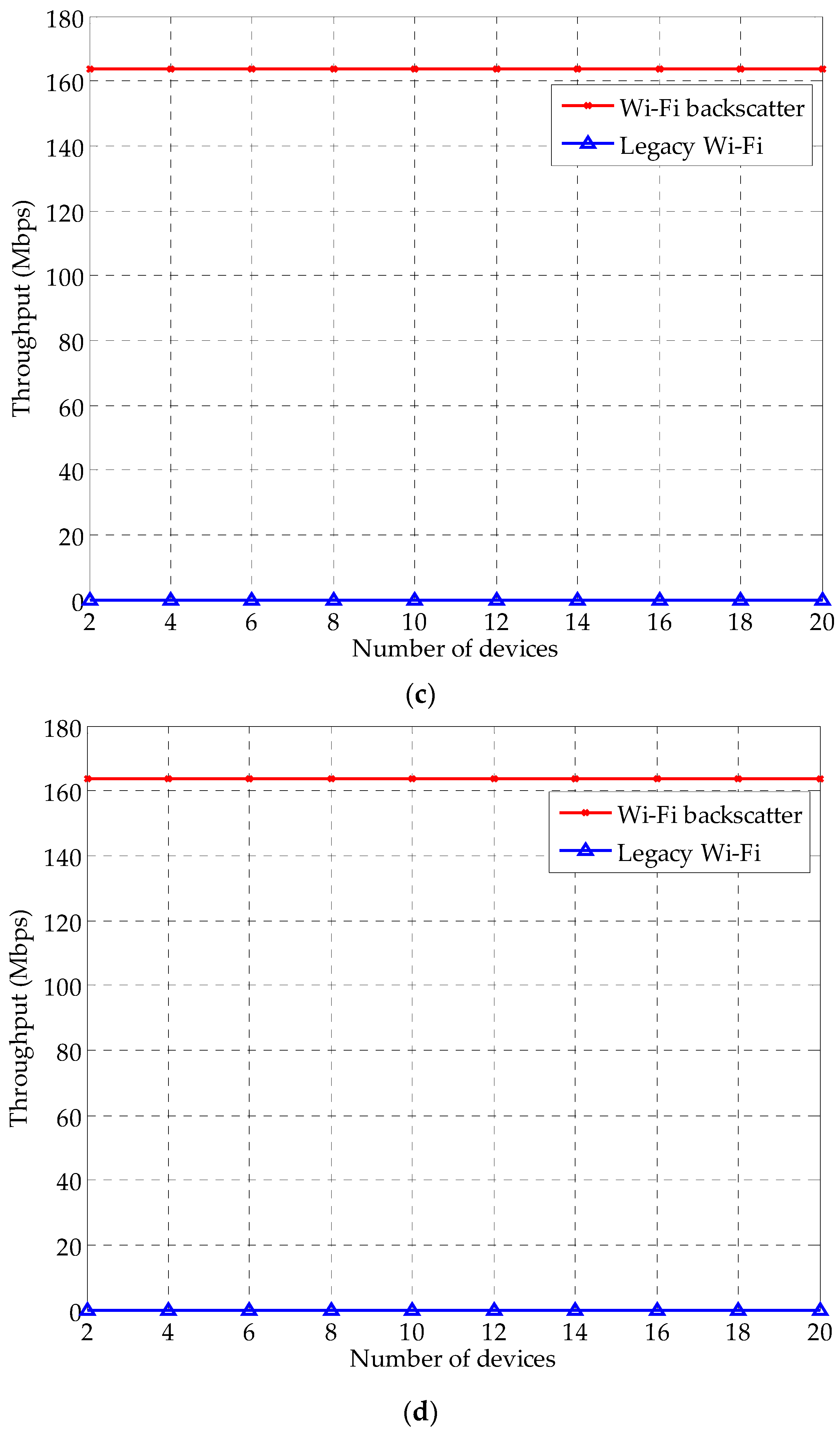
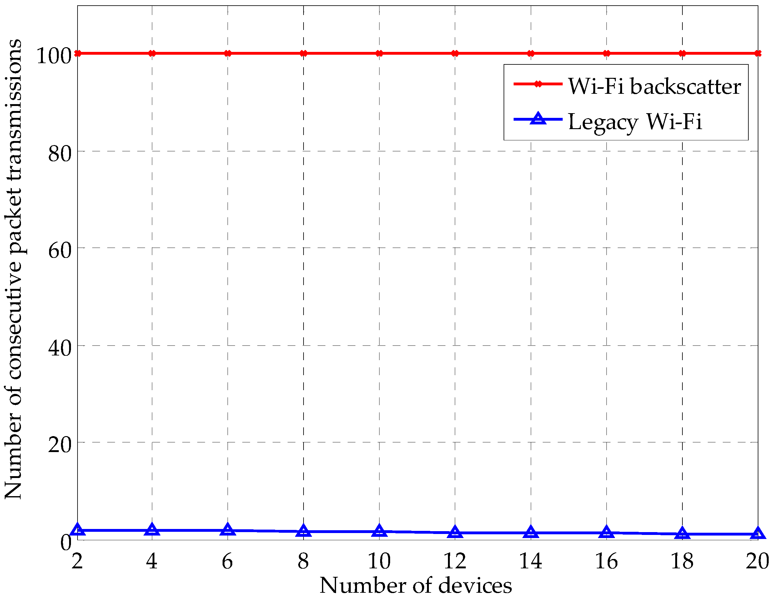
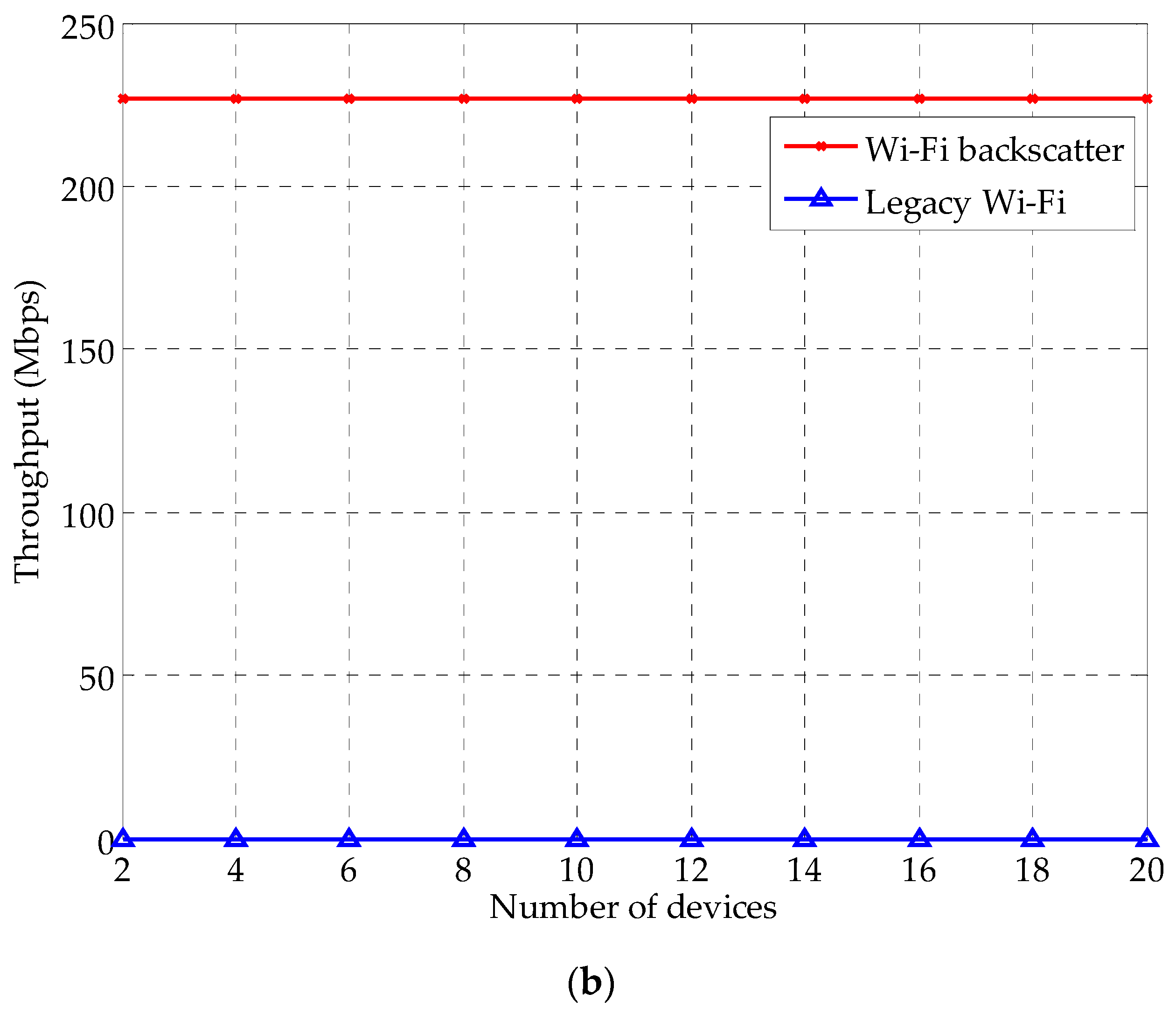
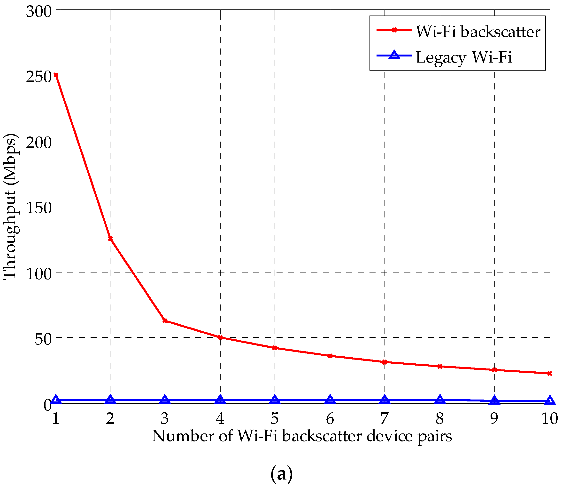
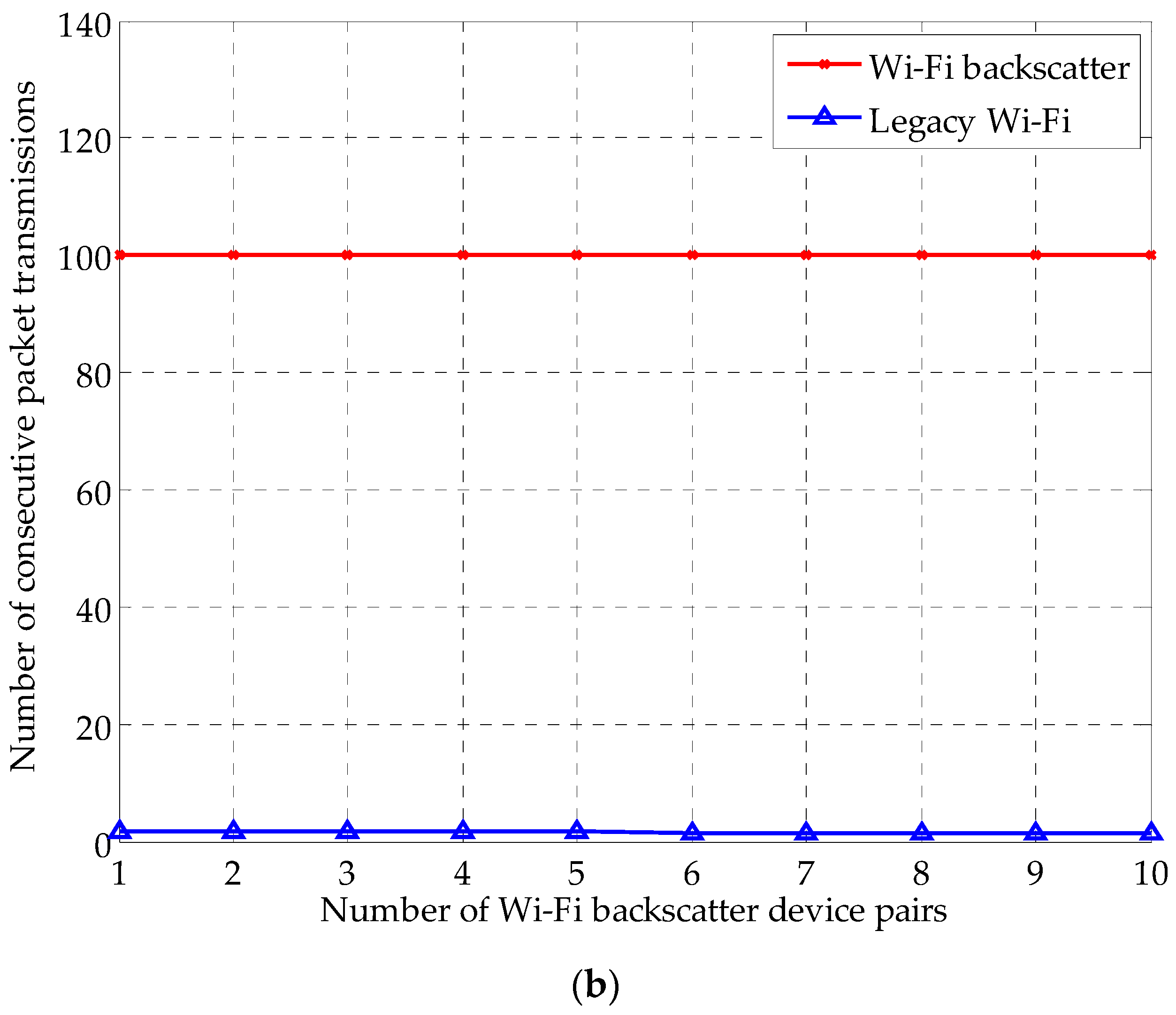
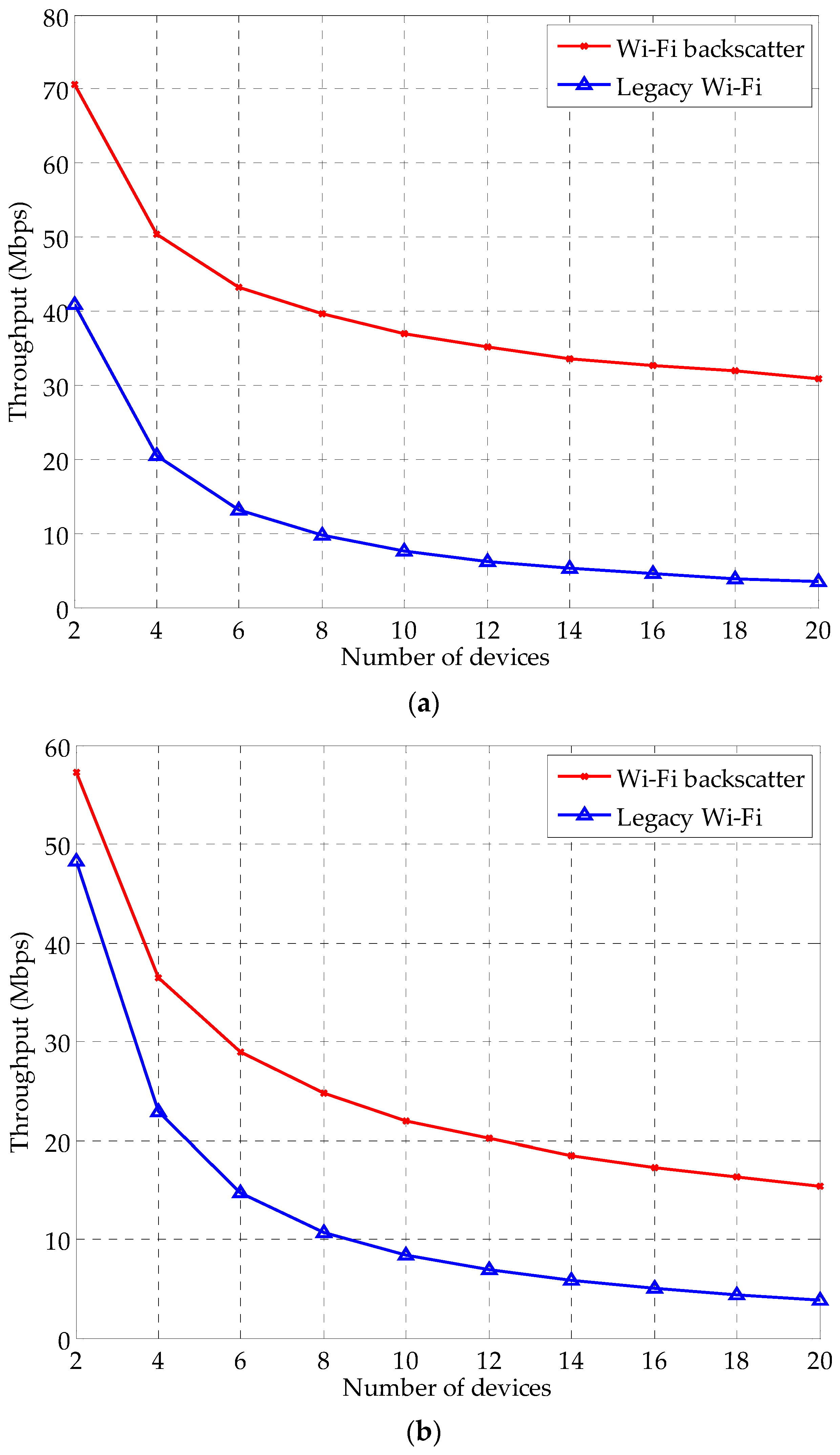
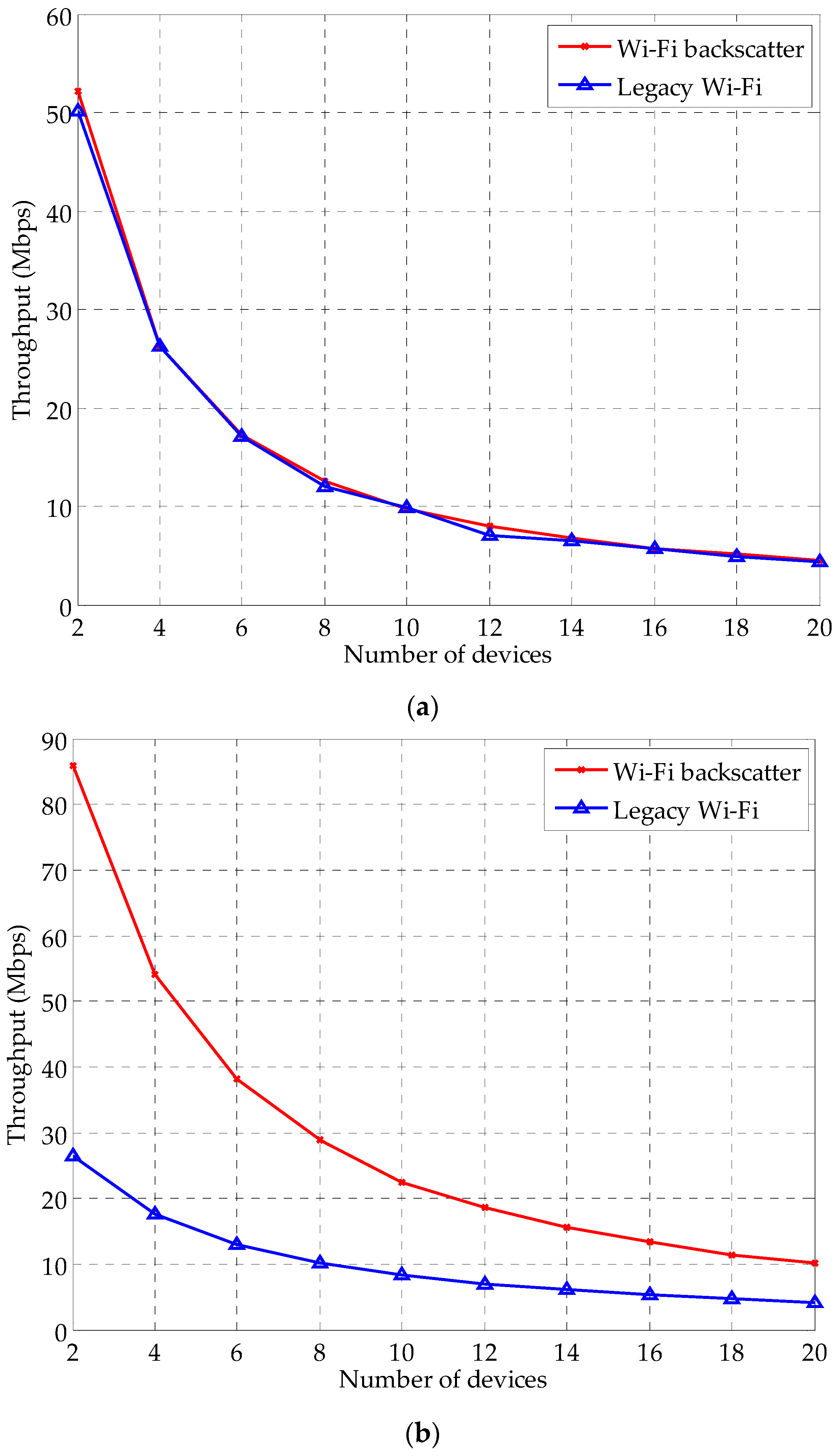
4.2. Simulation Results

Figure 5 and Figure 6 show the variation of average throughput for the Wi-Fi backscatter and legacy Wi-Fi devices when the number of devices is changed. In these simulations, only a single MAC configuration is employed for the Wi-Fi backscatter devices (i.e., separate cases). In Figure 5a,b, the Wi-Fi backscatter devices employ the “CSMA/CA starting with SIFS” and the “freezing of the backoff period”, respectively. Overall, the MAC configuration can improve the average throughput of Wi-Fi backscatter devices. The CSMA/CA starting with SIFS and the freezing of the backoff period improves the throughput by 85% and 29%, respectively. This is because the Wi-Fi backscatter devices have a higher priority of initial channel access than the legacy Wi-Fi devices in both cases. Specifically, the former can reduce the waiting time for channel access, and the latter can reduce the backoff delay when collision occurs.
The variation of throughput for “reduced CWmin” is shown in Figure 6. From the results, we observe that the reduced CWmin has the most significant effect on the channel occupancy. In Figure 6a, the throughput performance of the Wi-Fi backscatter and legacy Wi-Fi devices is almost the same, since both devices maintain the same value of CWmin. In this case, the throughput performance of each device is slightly different, since the device randomly selects the number of backoff slots (i.e., [0, CWmin]). When the CWmin of the Wi-Fi backscatter devices is reduced to 7 and 3 (i.e., Figure 6b,c), the Wi-Fi backscatter devices obtain higher throughput compared with the case where CWmin = 15 because they have fewer backoff slots than the legacy Wi-Fi devices. In Figure 6d, CWmin is set to 1. In this case, the Wi-Fi backscatter devices exhibit the highest throughput. The reason for this is that the number of backoff slots, which is the main cause of channel-access delay, selected is only to “0” or “1.” However, the separate cases cannot guarantee dominant-channel occupancy for the Wi-Fi backscatter devices when the number of devices increases. This is because the increased number of devices leads to the increased number of legacy Wi-Fi devices with a small value of CWmin.
Figure 7 shows the variation of average throughput for the composite cases where two or more MAC configurations are simultaneously employed for the Wi-Fi backscatter devices. Similar to the separate cases, the channel occupancy of the Wi-Fi backscatter devices is higher than that of the legacy Wi-Fi devices. However, the dedicated devices in composite cases exhibit higher average throughput than separate cases. This is because the advantages of each configuration are compositely applied to the Wi-Fi backscatter devices. Specifically, as shown in Figure 7a, the Wi-Fi backscatter exhibit 128% higher average throughput when the CSMA/CA starting with SIFS and freezing of the backoff period are employed at the same time. In composite cases, the Wi-Fi backscatter devices can dominantly occupy the channel. In Figure 7b, the Wi-Fi backscatter devices occupy 95% of the channel on average, since they use a small CWmin and fixed backoff period. In particular, as shown in Figure 7c,d, when CWmin is set to 1 and the duration of DIFS is set to 16 μs (i.e., SIFS) and when all configurations are simultaneously employed, the Wi-Fi backscatter devices dominantly occupy the channel.
Figure 8 and Figure 9 show the variation of the number of consecutive packet transmissions and throughput for the burst transmission, respectively. For the burst transmission, we set the Wi-Fi helper to transmit 100 packets consecutively. Figure 8 exhibits the variation of the number of burst transmissions when the number of devices increases. The Wi-Fi helper transmits 100 packets without any interruption. The reason for this is that they wait only for SIFS between consecutive packets. The neighboring legacy Wi-Fi devices use the CSMA/CA mechanism, which causes DIFS and random backoff delay; thus, they do not have a chance to transmit packets during the burst transmission. The number of consecutive packet transmissions of the legacy Wi-Fi devices decreases slightly when the number of devices increases, since the number of devices that have to compete for channel access increases.
Figure 9 shows the variation of throughput for burst transmission. In Figure 9a, the Wi-Fi backscatter devices employ burst transmission without MAC configurations for initial channel access. In this case, the throughput of the Wi-Fi backscatter devices decreases as the number of devices increases. The reason for this is that both types of devices have the same chance of channel access due to the use of CSMA/CA. Figure 9b shows the variation of throughput of the Wi-Fi backscatter devices when they use all of the MAC configurations. The simulation results demonstrate that the Wi-Fi backscatter devices can dominantly occupy the wireless channel. In this case, the Wi-Fi backscatter devices always access the channel earlier than the others, since they use the CSMA/CA starting with SIFS, freezing of the backoff period, and reduced CWmin (i.e., CWmin = 1). In addition, Wi-Fi helper transmits the packets successively without any interruption because they only wait for SIFS between consecutive packets.
Figure 10 shows the throughput variation and the number of consecutive packet transmissions for multiple pairs of Wi-Fi backscatter devices. In the simulation, 20 pairs of devices are deployed in total; the number of Wi-Fi backscatter device pairs started from one and rose to 10 in single-step increments, and the rest is set to the pairs of legacy Wi-Fi devices. All MAC configurations are employed for the pairs of Wi-Fi backscatter devices, and CWmin is set to three. In addition, the number of consecutive packets for burst transmission is set to 100. In Figure 10a, the Wi-Fi backscatter devices generally exhibit higher throughput than those of the legacy Wi-Fi due to the use of DCO. However, it sharply decreases as the number of Wi-Fi backscatter device pairs increases, because each Wi-Fi helper competes with all others for channel access using CSMA/CA. Figure 10b shows the number of consecutive packet transmissions when deploying multiple pairs of Wi-Fi backscatter devices. In this figure, the Wi-Fi helper transmits 100 packets without interruption, because the neighboring Wi-Fi helpers are not allowed to engage in packet transmission during the burst transmission.

5. Conclusions

This paper presents DCO to guarantee the timeliness and reliability of the IIoT system. The DCO is designed to provide high-priority channel access and reliable burst transmission. For the former, three types of MAC configurations are considered: “CSMA/CA starting with SIFS”, “freezing of the backoff period”, and “reduced CWmin.” For the latter, we consider the SIFS between consecutive packets instead of DIFS. The simulation results show that the DCO can guarantee the dominant-channel occupancy of Wi-Fi backscatter devices regardless of the interference from other legacy Wi-Fi devices in the vicinity. The CSMA/CA starting with SIFS and the freezing of the backoff period can improve the channel occupancy by 85% and 29%, respectively. The reduced CWmin is the most effective MAC configuration for the initial channel access in separate cases. When CWmin = 1, most of the shared wireless channel is occupied by Wi-Fi backscatter devices. Moreover, the Wi-Fi backscatter devices achieve much higher channel occupancy than the separate cases when multiple MAC configurations are used compositely. If all of the MAC configurations with CWmin = 1 are employed for the Wi-Fi backscatter devices, they always have the highest priority for channel access. In the case where the Wi-Fi backscatter devices use the SIFS between consecutive packets, they transmit the packets successively regardless of the transmissions of the legacy Wi-Fi devices in the vicinity. This paper focuses on the design of DCO and performance evaluation via experimental simulation. Future work will be directed towards implementing DCO using available Wi-Fi open source device drivers, since this requires the additional low MAC development of a Wi-Fi helper. In particular, we will evaluate and verify the feasibility of DCO in real IIoT environments through such an implementation.

Acknowledgments

This work was supported by NRF (National Research Foundation of Korea) Grant funded by the Korean Government (NRF-2016-Fostering Core Leaders of the Future Basic Science Program/Global Ph.D. Fellowship Program) (2016H1A2A1908620). This research was also supported by the Leading Human Resource Training Program of Regional Neo Industry through the National Research Foundation of Korea (NRF) funded by the Ministry of Science, ICT and Future Planning (2016H1D5A1910427).

Author Contributions

Eui-Jik Kim conceived and designed the overall research; Jung-Hyok Kwon interpreted and analyzed the data; Hwi-ho Lee and Yongseok Lim conducted the experimental simulation; Eui-Jik Kim and Jung-Hyok Kwon wrote the paper; and Eui-Jik Kim guided the research direction and supervised the entire research process.

Conflicts of Interest

The authors declare no conflict of interest.

References

  1. Gilchrist, A. Designing Industrial Internet Systems. In Industry 4.0, 1st ed.; Apress: New York, NY, USA, 2016; pp. 87–118. [Google Scholar]
  2. Gubbi, J.; Buyya, R.; Marusic, S.; Palaniswami, M. Internet of Things (IoT): A vision, architectural elements, and future directions. Future Gener. Comput. Syst. 2013, 29, 1645–1660. [Google Scholar] [CrossRef]
  3. Wang, J.; Hassanieh, H.; Katabi, D.; Indyk, P. Efficient and reliable low-power backscatter networks. In Proceedings of the ACM SIGCOMM 2012 Conference on Applications, Technologies, Architectures, and Protocols for Computer Communication, Helsinki, Finland, 13–17 August 2012; ACM: New York, NY, USA, 2012. [Google Scholar]
  4. Da Xu, L.; He, W.; Li, S. Internet of things in industries: A survey. Trans. Ind. Informat. 2014, 10, 2233–2243. [Google Scholar] [CrossRef]
  5. Zhu, R.; Zhang, X.; Liu, X.; Shu, W.; Mao, T.; Jalaian, B. ERDT: Energy-efficient reliable decision transmission for intelligent cooperative spectrum sensing in industrial IoT. IEEE Access 2015, 3, 2366–2378. [Google Scholar] [CrossRef]
  6. Kellogg, B.; Parks, A.; Gollakota, S.; Smith, J.R.; Wetherall, D. Wi-fi backscatter: Internet connectivity for RF-powered devices. In Proceedings of the 2014 ACM Conference on SIGCOMM, Chicago, IL, USA, 17–22 August 2014; ACM: New York, NY, USA, 2014. [Google Scholar]
  7. Kim, T.Y.; Kim, E.-J. Uplink scheduling of MU-MIMO gateway for massive data acquisition in Internet of things. J. Supercomput. 2016, 1–15. [Google Scholar] [CrossRef]
  8. Neto, J.B.B.; Silva, T.H.; Assunção, R.M.; Mini, R.A.; Loureiro, A.A. Sensing in the collaborative Internet of things. Sensors 2015, 15, 6607–6632. [Google Scholar] [CrossRef] [PubMed]
  9. IEEE Standard for Information Technology—Telecommunications and Information Exchange between Systems Local and Metropolitan Area Networks—Specific Requirements—Part 11: Wireless LAN Medium Access Control (MAC) and Physical Layer (PHY) Specifications; IEEE: New York, NY, USA, 2003.
  10. IEEE Standard for Information Technology–Local and Metropolitan Area Networks–Specific Requirements–Part 11: Wireless LAN Medium Access Control (MAC) and Physical Layer (PHY) Specifications–Amendment 8: Medium Access Control (MAC) Quality of Service Enhancements; IEEE: New York, NY, USA, 2005.
  11. Kim, E.-J.; Kwon, J.-H.; Choi, K.; Shon, T. Unified medium access control architecture for resource-constrained machine-to-machine devices. ACM T. Embed. Comput. Syst. 2016, 15, 40:1–40:17. [Google Scholar] [CrossRef]
  12. Xie, S.; Low, K.S.; Gunawan, E. A Distributed transmission rate adjustment algorithm in heterogeneous CSMA/CA networks. Sensors 2015, 15, 7434–7453. [Google Scholar] [CrossRef] [PubMed]
  13. Davenport, C.J.; Rigelsford, J.M.; Zhang, J.; Altan, H. Periodic comb reflection frequency selective surface for interference reduction. In Proceedings of the Antennas and Propagation Conference (LAPC), Loughborough, UK, 11–12 November 2013; IEEE: New York, NY, USA, 2013. [Google Scholar]
  14. Li, Y.; Fu, L.; Ying, Y.; Sun, Y.; Chi, K.; Zhu, Y. Goodput optimization via dynamic frame length and charging time adaptation for backscatter communication. Peer-to-Peer Netw. Appl. 2016, in press. [Google Scholar] [CrossRef]
  15. Kim, E.-J.; Youm, S.; Kang, C.-H. Power-controlled topology optimization and channel assignment for hybrid MAC in wireless sensor networks. IEICE Trans. Commun. 2011, E94-B, 2461–2472. [Google Scholar] [CrossRef]
  16. Bhandari, S.; Moh, S. A priority-based adaptive MAC protocol for wireless body area networks. Sensors 2016, 16, 401:1–401:16. [Google Scholar] [CrossRef] [PubMed]
  17. Bharadia, D.; Joshi, K.R.; Koraru, M.; Katti, S. Backfi: High throughput WiFi backscatter. In Proceedings of the 2015 ACM conference on Special Interest Group on Data Communication, London, UK, 17–21 August 2015; ACM: New York, NY, USA, 2015. [Google Scholar]
  18. Talla, V.; Kellogg, B.; Ransford, B.; Naderiparizi, S.; Gollakota, S.; Smith, J.R. Powering the next billion devices with Wi-Fi. In Proceedings of the 11th International Conference on emerging Networking Experiments and Technologies, Heidelberg, Germany, 1–4 December 2015; ACM: New York, NY, USA, 2015. [Google Scholar]
  19. Scalia, L.; Tinnirello, I.; Tantra, J.W.; Foh, C.H. WLC24-1: Dynamic MAC parameters configuration for performance optimization in 802.11 e networks. In Proceedings of the IEEE Globecom 2006, San Francisco, CA, USA, 27 November–1 December 2006; IEEE: New York, NY, USA, 2006. [Google Scholar]
  20. IEEE Standard for Information Technology–Local and Metropolitan Area Networks–Specific Requirements–Part 11: Wireless LAN Medium Access Control (MAC) and Physical Layer (PHY) Specifications–Amendment 5: Enhancements for Higher Throughput; IEEE: New York, NY, USA, 2009.
  21. Zhang, Z.; Tian, Z.; Zhou, M.; Li, Z.; Wu, Z.; Jin, Y. WIPP: Wi-Fi compass for indoor passive positioning with decimeter accuracy. Appl. Sci. 2016, 6, 108:1–108:18. [Google Scholar] [CrossRef]
  22. Maruta, K.; Iwakuni, T.; Ohta, A.; Arai, T.; Shirato, Y.; Kurosaki, S.; Iizuka, M. First eigenmode transmission by high efficient CSI estimation for multiuser massive MIMO using millimeter wave bands. Sensors 2016, 16, 1051:1–1051:16. [Google Scholar] [CrossRef] [PubMed]
  23. Kwon, J.-H.; Chang, H.S.; Shon, T.; Jung, J.-J.; Kim, E.-J. Neighbor stability-based VANET clustering for urban vehicular environments. J. Supercomput. 2016, 72, 161–176. [Google Scholar] [CrossRef]
  24. Park, H.; Lee, C.; Lee, Y.S.; Kim, E.-J. Performance analysis for contention adaptation of M2M devices with directional antennas. J. Supercomput. 2015, 72, 3387–3408. [Google Scholar] [CrossRef]
  25. OpenWrt wireless freedom. Available online: https://openwrt.org (accessed on 13 November 2016).
  26. DD-WRT Wiki. Available online: https://www.dd-wrt.com/wiki/index.php/Main_Page (accessed on 13 November 2016).
  27. Tomato firmware. Available online: http://www.polarcloud.com/tomato (accessed on 13 November 2016).
  28. The MadWifi project. Available online: http://madwifi-project.org (accessed on 13 November 2016).
Figure 1. Wi-Fi backscatter uplink communication: (a) architecture; and (b) operation.
Applsci 06 00427 g001
Figure 2. Comparison of initial channel access: (a) DCO; and (b) legacy Wi-Fi.
Applsci 06 00427 g002
Figure 3. Example of burst transmission of DCO.
Applsci 06 00427 g003
Figure 4. Examples of network topology: (a) four devices; (b) eight devices; (c) 14 devices; and (d) 20 devices.
Applsci 06 00427 g004
Figure 5. Variation of throughput for separate cases: (a) CSMA/CA starting with SIFS; and (b) Freezing of backoff period.
Applsci 06 00427 g005
Figure 6. Variation of throughput for separate cases: (a) reduced CWmin = 15; (b) reduced CWmin = 7; (c) reduced CWmin = 3; and (d) reduced CWmin = 1.
Applsci 06 00427 g006aApplsci 06 00427 g006b
Figure 7. Variation of throughput for composite cases: (a) CSMA/CA starting with SIFS + freezing of backoff period; (b) freezing of backoff period + reduced CWmin = 1; (c) CSMA/CA starting with SIFS + reduced CWmin = 1; and (d) all of the MAC configurations.
Applsci 06 00427 g007aApplsci 06 00427 g007b
Figure 8. Variation of the number of consecutive packet transmissions.
Applsci 06 00427 g008
Figure 9. Variation of throughput for burst transmission: (a) SIFS between consecutive packets without MAC configurations for initial channel access; and (b) all of the MAC configurations.
Applsci 06 00427 g009aApplsci 06 00427 g009b
Figure 10. Variation of throughput and the number of consecutive packet transmissions for multiple pairs of Wi-Fi backscatter devices: (a) throughput; and (b) number of consecutive packet transmissions.
Applsci 06 00427 g010aApplsci 06 00427 g010b
Table 1. Simulation parameters.
ParameterValueParameterValue
PHY/MAC modelIEEE 802.11nTraffic applicationCBR
Simulation time1000 msDate rate300 Mbps
SIFS16 μsPayload2304 bytes
DIFS34 μsPHY header16 bytes
Slot time9 μsMAC header30 bytes
Maximum retransmission6CWmin, CWmax15, 511

