Review

Characteristics and Applications of Spatiotemporally Focused Femtosecond Laser Pulses

1
College of Physics and Electronic Information, Luoyang Normal University, Luoyang 471000, China
2
State Key Laboratory of High Field Laser Physics, Shanghai Institute of Optics and Fine Mechanics, Chinese Academy of Sciences, Shanghai 201800, China
3
Luoyang Institute of Electro-Optical Equipment, Aviation Industry Corporation of China, Luoyang 471000, China
*
Author to whom correspondence should be addressed.
Appl. Sci. 2016, 6(12), 428; https://doi.org/10.3390/app6120428
Submission received: 12 October 2016 / Revised: 1 December 2016 / Accepted: 7 December 2016 / Published: 13 December 2016
(This article belongs to the Special Issue Ultrashort Optical Pulses)

Abstract

:
Simultaneous spatial and temporal focusing (SSTF) of femtosecond laser pulses gives rise to strong suppression of nonlinear self-focusing during the propagation of the femtosecond laser beam. In this paper, we begin with an introduction of the principle of SSTF, followed by a review of our recent experimental results on the characterization and application of the spatiotemporally focused pulses for femtosecond laser micromachining. Finally, we summarize all of the results and give a future perspective of this technique.

1. Introduction

Femtosecond laser pulses have been widely used for three-dimensional (3D) micromachining on both micro and nano scales [1,2,3,4,5,6]. The tightly-focused, intense, femtosecond laser pulses intrinsically provide capabilities of 3D micro and nano fabrication due to efficient confinement of the nonlinear interactions within the focal volume [2]. For many applications, such as writing optical waveguides or fabricating microchannels, a 3D isotropic resolution is necessary. However, because of the mismatch between the beam transverse radius and the Rayleigh length at the focus, the single-path transverse writing method (i.e., the writing direction perpendicular to the laser propagation direction) intrinsically creates asymmetric cross-sections with conventionally-focused femtosecond laser pulses [7]. To solve the problem, several pulse-shaping techniques have been proposed, including astigmatic beam shaping [8], slit beam shaping [9], and crossed-beam shaping [10], etc. However, none of these techniques can produce a true spherical focal spot with isotropic resolutions in all three dimensions of space. By applying the simultaneous spatial and temporal focusing (SSTF) technique in femtosecond laser micromachining, it is shown that such a problem can be settled appropriately.
Simultaneous spatial and temporal focusing, which was originally developed to improve the depth resolution in the process of 3D-resolved imaging in 2005 [11,12], has attracted much attention due to its potential applications in many research fields [13,14,15,16,17]. In 2010, He et al. firstly applied the SSTF technique in femtosecond laser micromachining to achieve 3D isotropic resolution in fabrication of microfluidic channels with a circular cross-section regardless of the direction of sample translation [18]. Until now, the SSTF technique is the only method that allows a 3D isotropic fabrication resolution with a single focal lens [18,19,20], and the applications of such a technique in femtosecond laser micromachining have been extensively studied. Almost in the same time, SSTF has also extended to femtosecond laser filamentation for reducing the nonlinear self-focusing which is the major obstacle to achieving high peak intensity in the filament [21,22]. Shortly after the establishment of the technique, it was discovered that the SSTF spot has some unconventional characteristics, including a pulse front tilt (PFT) and an intensity plane tilt [23,24]. Moreover, the interaction between the SSTF pulses and transparent media can induce some intriguing phenomena, such as a nonreciprocal writing effect, second harmonic generation in isotropic media, and curved plasma formation in fused silica glass [23,25,26]. Until now, the physics mechanism of the nonlinear interaction of SSTF pulses with transparent materials has not been fully understood.
In this paper, we review the major experimental results related to characterization and application of SSTF pulses obtained by us in the past few years. The paper is organized as follows: In Section 2, we introduce the basic principles of the SSTF technique and the main characteristics of SSTF pulses. From Section 3, Section 4 and Section 5, we show the applications of SSTF pulses in femtosecond laser micromachining with improved axial resolution, femtosecond laser filamentation with enhanced peak intensity, and creating unconventional plasma behaviors, respectively. A summary and an outlook are given in Section 6.

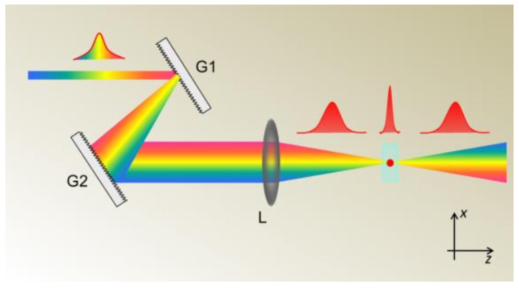
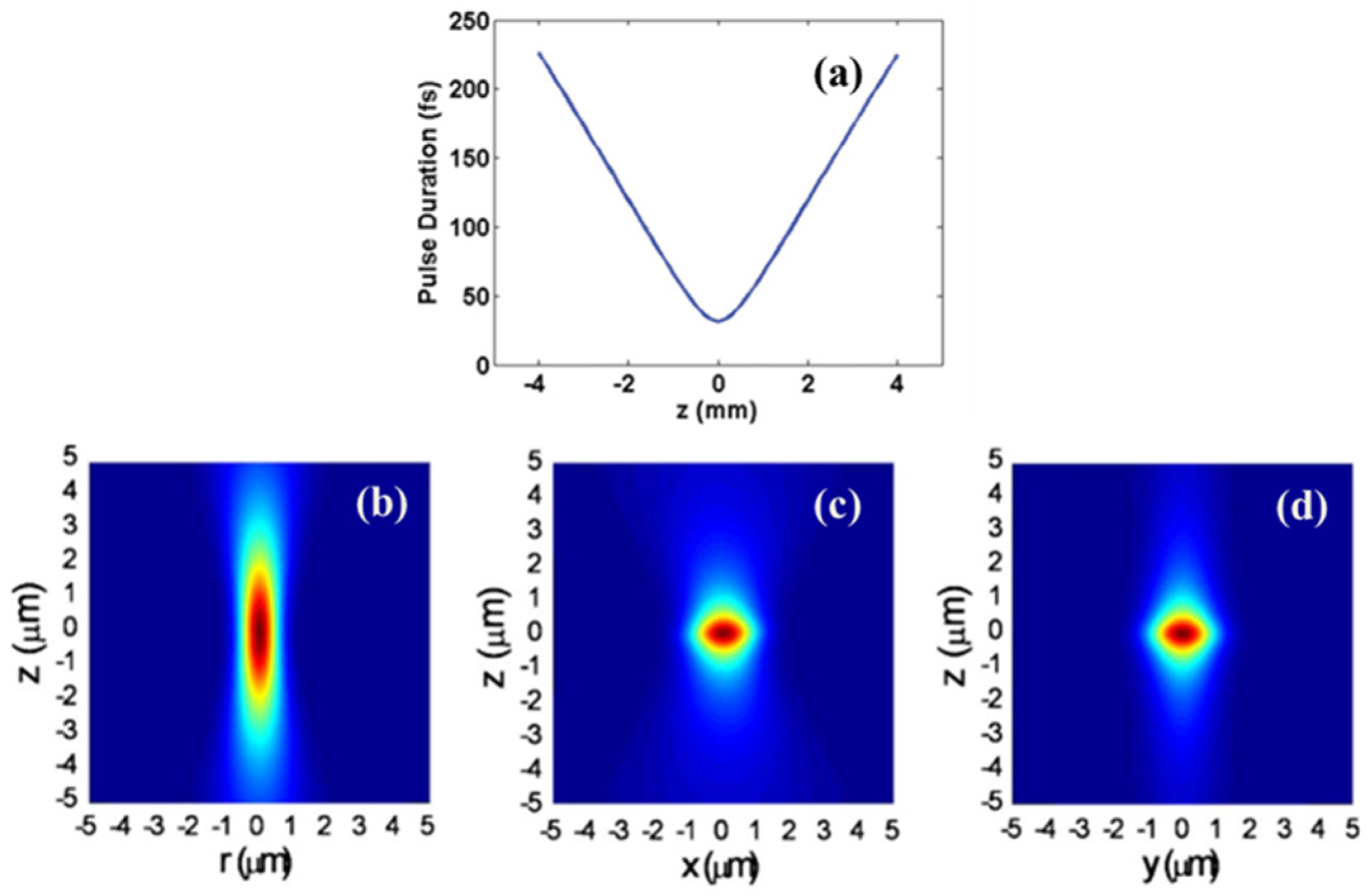
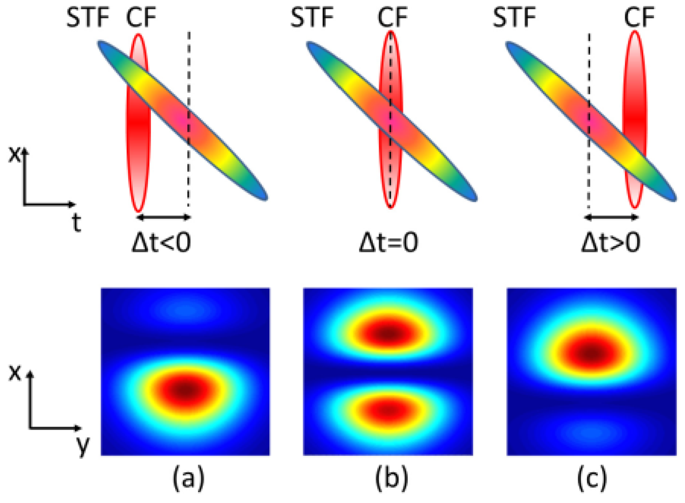
2. The Basic Principles of the SSTF Technique and Characteristics of SSTF Pulses

Figure 1 schematically shows a typical SSTF system [27]. In the following discussions, in order to avoid any confusion, we refer to SSTF as this scheme. As it can be seen in Figure 1, the pre-chirped femtosecond laser pulses propagating along the z direction are firstly dispersed laterally along the x direction by a pair of gratings (G1, G2). The spatially-separated frequencies are then recombined by a focusing lens (L). Only at the geometric focus of the focusing lens, the different spectral components spatially overlap, leading to the shortest pulse duration as well as the highest peak intensity. However, when moving away from the geometrical focal spot, the peak intensity will decrease rapidly due to the broadening of the pulse duration, as shown in Figure 2 [18,21]. In such a manner, the peak intensity is strongly localized near the geometrical focus, and the focal depth of the SSTF pulses are greatly reduced in comparison with conventional focused pulses (see Figure 2b–d). The characteristics of SSTF pulses mentioned above can be simulated accurately based on Fresnel diffraction integral theory, which can be found in the Appendix.
Interestingly, it was discovered that the SSTF beam naturally creates a focal spot with a tilted pulse front [28,29], which can induce a nonreciprocal writing effect in isotropic transparent materials [23]. As it can be seen in Figure 3, it is assumed that the input laser pulses carries the spatial chirp along the x axis before the focusing lens, and the laser pulses will arrive at the focal plane at different times, which is known as the pulse front tilt (PFT) effect. With experimental and theoretical investigations, it is verified that the PFT at the focus of SSTF pulses has several prominent features. The origin of the PFT effect is proved to be mainly related to the lateral separation of the different spectral components of the pulses introduced by a pair of gratings, which cannot be eliminated by introducing the initial PFT in the opposite direction [28]. Additionally, the degree of PFT, which is several orders of magnitude higher than that of the conventional femtosecond laser pulses, can be controlled by changing the spatial chirp before the focusing lens.
In order to quantitatively investigate the degree of PFT of a SSTF pulse at the focus, an interferometric method was proposed by Wang et al. in 2015. The basic principle of the measuring method is illustrated in Figure 4 [30]. A conventional focused pulse is introduced as a reference pulse, and interference occurs in the focal plane between the reference pulse and SSTF pulse. By changing the time delay between the reference pulse and the SSTF pulse, the interference pattern of two pulses forms in the focal plane will shift linearly. Thus, by plotting the shift of the interference fringe as a function of the time delay between the two pulses, the tilting angle of the SSTF pulse can be obtained [30].
Additionally, the SSTF spot have a tilted intensity distribution near the focus. In 2014, He et al. reported such a phenomenon by experimental examination of two-photon fluorescence excitation generated by SSTF pulses at the focus [24]. Figure 5a,c,e show two-photon fluorescence images in different planes produced using the SSTF scheme and the traditional focusing scheme, respectively, and the corresponding simulation results are shown in Figure 5b,d,f. It is obvious that the intensity distributions show different features. When utilizing the SSTF scheme, the titled intensity distribution of the focal spot can be observed from the XZ plane, which is parallel to the spatial chirp before the lens. However, in the YZ plane, the fluorescence intensity distribution is symmetrical (i.e., the intensity tilting disappear in this plane). When the spatial chirp before the lens is removed (i.e., using the conventional focusing scheme), the intensity distribution is always symmetrical regardless of the orientation of imaging plane. It has been verified by theoretical analysis that the intensity tilt effect results from the varying chirp of the local light field intrinsically existing in the focal plane [24].

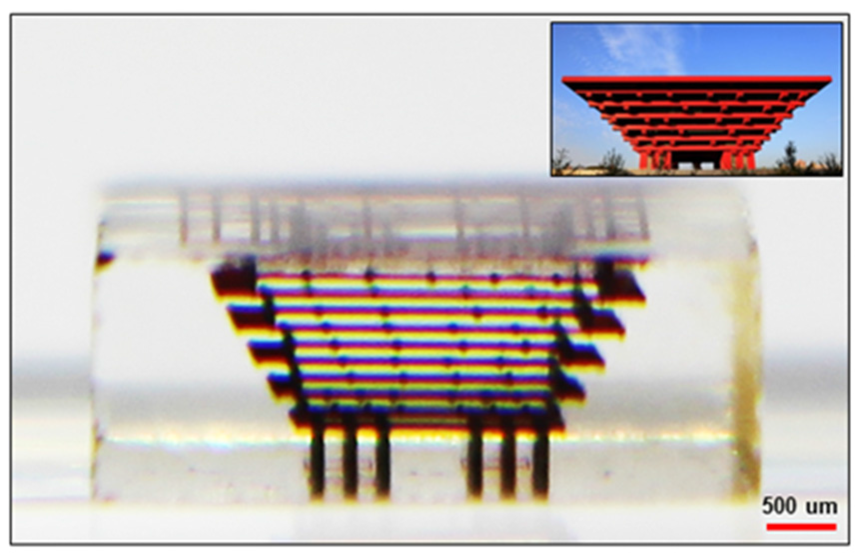
3. Applications of the SSTF Technique in Femtosecond Laser Micromachining

In 2010, He et al. firstly demonstrated that the SSTF technique allows internal processing in glass with 3D isotropic resolution using a single objective lens. They fabricated micro-channels with circular cross-sections along different writing directions, as shown in Figure 6 [18]. It can be seen that the symmetrical cross-section can be achieved regardless of translation direction of the femtosecond laser beam. By changing the beam size and the average power of the femtosecond laser, it is found that the axial resolution of the fabrication can be continuously controlled. In addition, the aspect ratio of the cross-section can be controlled by changing the spatial chirp before the objective lens through theoretical simulation [19]. More recently, Tan et al. reported that a 3D isotropic spatial resolution of 100 μm can be achieved with a low numerical aperture lens by utilizing the spatiotemporal focusing technique [31]. This leads to significant enhancement of the fabrication efficiency due to the realization of high-throughput 3D femtosecond laser fabrication. Figure 7 demonstrates the fabrication of a complex, large-scale 3D model of the China Pavilion of EXPO 2010 (world exhibition of exposition) using the SSTF technique [31]. Despite its large size and the low repetition rate of the femtosecond laser used in the experiment, the structure was completed within a few minutes thanks to the large spherical focal spot produced by SSTF.
Since the SSTF technique has been proposed, its applications in the field of laser micromachining have attracted significant attention. For instance, Vitek et al. demonstrated that the SSTF pulses are able to selectively ablate the back surface of a sample with low numerical aperture through 6 mm thick transparent materials [32]. The underlying mechanism can be attributed to the suppression of self-focusing out of geometrical focus due to the broadening of the pulse duration [32]. Additionally, such characteristics can also benefit the precision enhancement in femtosecond laser processing for tissue ablation, which is particularly important in fs-ophthalmic surgery [13,14]. More interestingly, it has been discovered that when SSTF pulses are employed for direct writing in transparent materials, a nonreciprocal writing effect occurs, i.e., the fabrication quality highly depends on the writing direction [23]. Although the mechanism of such an effect has not been fully understood, its connection to the PFT has been confirmed by several recent investigations [23,33,34].

4. Applications of SSTF Technique in Femtosecond Laser Filamentation

Another subject of great interest for applying SSTF technique is in the field of femtosecond filamentation. Owing to the interplay between Kerr focusing and plasma defocusing, a femtosecond laser beam can transform itself into a thin and long light string, which propagates to a remote place without divergence [35]. The intensity inside is generally clamped at 1013~1014 W/cm2 as plasma can be efficiently generated at such intensities which, in turn, induces strong defocusing of the light in the filament [35,36]. The clamped intensity in the filament can be enhanced by tight focusing, as the strong geometric focusing can compensate the plasma-induced defocusing to some extent. Unfortunately, the filament cannot be launched far away with the tight focusing, which limits its applications in remote sensing.
In 2011, Zeng et al. demonstrated that the difficulties can be settled using the SSTF technique [21]. Under the same operating distance, the clamped peak intensity in the core of the filament has reached a higher level with the SSTF pulses than that obtained with the conventional focusing scheme (see Figure 8a for more details). This is mainly due to the suppression of the self-focusing before the geometric focus which allows the pulses the approach the geometric focal plane in a more linear fashion. Only near the geometric focal plane, both the optimal conditions for spatial and temporal focusing can be simultaneously reached to give rise to a sharp increase of the peak intensity. The plasma defocusing effect is, therefore, hampered owing to the relatively lower peak intensity of the SSTF pulses away from the geometrical focal plane. Additionally, the length of the filament generated by SSTF pulses is nearly 25 times shorter than that generated by the conventional focusing scheme, which is a clear indication of the suppressed self-focusing effect (see Figure 8b,c for details). Another manifestation of the suppressed nonlinear propagation is the suppression of supercontinuum generation in the filament, which is verified by investigating the optical breakdown spectra in water [14].
Due to the improvement of the clamped intensity inside the filament, the SSTF technique can be applied in remote sensing spectroscopy. Researchers show that significant enhancement of fluorescence signals can be achieved in filament-induced breakdown spectroscopy. The typical spectrum achieved on iron and aluminum samples from 22 m away using SSTF pulses are demonstrated in Figure 9 [37]. By using SSTF pulses, approximately three- and four-fold enhancements of the fluorescence signals were observed from iron and aluminum targets, respectively [37]. The results can be attributed to the nonlinear dependence of the fluorescence signals on the laser intensities at the targets.

5. Applications of SSTF Technique in Manipulation of Plasma Dynamics

In the previous section, we demonstrated the applications of the SSTF technique in femtosecond laser filamentation. More careful examination shows that the plasma behaviors in the SSTF field are intriguing. By recording the time-resolved shadowgraphs of the transient plasma induced by the SSTF pulses inside fused silica glass, it was discovered that the track of the plasma is significantly curved [26]. Figure 10 shows the time-resolved shadowgraphs of plasma produced by the SSTF pulses when the polarization conditions and pulse energy were varied. The plasma formation appears more pronounced when the polarization direction of the pump pulse is parallel to the spatial chirp of the SSTF pulses, as stronger photoionization can be achieved with such a polarization configuration. Moreover, the plasma track will bend itself more severely when photoionization appears stronger from the shadowgraph images. The bending of plasma tracks can be attributed to the asymmetric expansion of the plasma in the SSTF pulses, as the PFT of the SSTF pulses will generate unbalanced ponderomotive forces in the directions parallel and anti-parallel to the pulse front tilting [26]. It is noteworthy that when the plasma density distribution becomes asymmetric along the direction perpendicular to the optical axis, and the focused laser beam will be deflected toward the area where the plasma density is higher (i.e., similar to an optical fiber in which the light is reflected from the cladding where the refractive index is lower than the core), which leads to the bending of the plasma tracks.
Furthermore, in 2014, Li et al. reported an unexpected intense second harmonic generation in the gas chamber filled with 1 atm argon using the SSTF scheme, which seems counterintuitive in centrosymmetric media [25]. As it can be seen in Figure 11, when the polarization direction of the pump pulses is along x axis (i.e., linearly polarized along the direction of the spatial chirp), the SSTF pulses can generate a second harmonic efficiently with an extremely high signal-to-noise ratio. By changing the polarization of input laser pulses to the y axis (i.e., linearly polarized perpendicular to the direction of the spatial chirp), the second harmonic beam shows two lobes separated from each other and the signal-to-noise ratio is dramatically decreased. The underlying mechanism for such a second harmonic generation by the spatiotemporal focusing scheme is ascribed to the gradient of non-uniform plasma induced by the PFT of the SSTF pulses [25].

6. Summary and Outlook

To summarize, we have given a comprehensive review on the characteristics of SSTF pulses, and the applications of SSTF in femtosecond laser micromachining, femtosecond laser filamentation, and manipulation of plasma dynamics. In femtosecond laser micro and nano-fabrication, the SSTF technique has been applied for enhancing the axial resolution which is particularly useful for 3D processing inside glass and crystals. When the SSTF pulses are used in femtosecond laser filamentation, they naturally give rise to the enhancement of peak intensity within the filament and suppression of the nonlinear self-focusing during propagation. Remarkably, the interactions of the SSTF pulse with solid and gaseous media show unexpected behaviors, such as nonreciprocal writing in dielectric materials and second harmonic generation in centrosymmetric gas media. The physical mechanisms behind these unconventional phenomena are still under debate.
Since the SSTF technique was proposed, a lot of progress has been achieved in the research of interaction of the spatiotemporally focused femtosecond laser pulses with transparent media. However, it is worth noting that there are some unsettled problems in practical applications. For instance, the nonreciprocal writing effect, which is unfavorable to the fabrication of complex 3D structures, should be avoided when the SSTF technique is employed for direct writing in transparent materials. In order to propose a method to overcome such difficulty, systematically theoretical calculations, as well as further experimental investigation, are necessary in the follow-up work. Additionally, with the merits of the SSTF pulses, the SSTF technique has shown its advantage in high-throughput 3D femtosecond laser fabrication and high-speed biomedical imaging. Moreover, such a technique is also expected to be widely applied in surface nano/micro structuring and tissue engineering in the near future.

Acknowledgments

The work is supported by National Basic Research Program of China (2014CB921300), Key Scientific Research Project of Henan Province (17A140023) and Foundation for Fostering National Project of Luoyang Normal University (2015-PYJJ-001).

Author Contributions

C.J. and Z.W. prepared the manuscript under the supervision of Y.C.

Conflicts of Interest

The authors declare no conflict of interest.

Appendix

The propagation of the spatiotemporally-focused pulses can be derived based on Fresnel diffraction integral theory [18]. The intensity distribution of the laser after dispersed by the gratings can be described as:
E 1 ( x , y , ω ) = E 0 exp [ ( ω ω 0 ) 2 Δ ω 2 ] exp { [ x α ( ω ω 0 ) ] 2 + y 2 w in 2 } ,
where E 0 is the field amplitude, ω 0 is the center frequency, Δ ω is the bandwidth, α is the linear offset of each spectral components, ω in is the beam waist of input laser pulses. After passing the focusing lens, the laser field is:
E 2 ( x , y , ω ) = E 1 exp [ i k x 2 + y 2 2 f ] ,
where k is the wave vector, and f is the focal length.
Under the paraxial approximation, after propagating a distance from the lens, the laser field can be written as:
E 2 ( x , y , z , ω ) = exp ( i k z ) i λ z E 2 ( ξ , η , ω ) exp [ i k ( x ξ ) 2 + ( y η ) 2 2 z ] d ξ d η ,
By performing a Fourier transform, the laser intensity in the space and time domains can be obtained by:
I ( x , y , z , t ) = | E 2 ( x , y , z , ω ) exp ( i ω t ) d ω | 2 .

References

  1. Beresna, M.; Gecevičius, M.; Kazansky, P.G. Ultrafast laser direct writing and nanostructuring in transparent materials. Adv. Opt. Photonics 2014, 6, 293–339. [Google Scholar] [CrossRef]
  2. Sugioka, K.; Cheng, Y. Femtosecond laser three-dimensional micro- and nanofabrication. Appl. Phys. Rev. 2014, 1. [Google Scholar] [CrossRef]
  3. Osellame, R.; Hoekstra, H.J.W.M.; Cerullo, G.; Pollnau, M. Femtosecond laser microstructuring: An enabling tool for optofluidic lab-on-chips. Laser Photonics Rev. 2011, 5, 442–463. [Google Scholar] [CrossRef]
  4. Ams, M.; Marshall, G.D.; Dekker, P.; Piper, J.A.; Withford, M.J. Ultrafast laser written active devices. Laser Photonics Rev. 2009, 3, 535–544. [Google Scholar] [CrossRef]
  5. Kawata, S.; Sun, H.B.; Tanaka, T.; Takada, K. Finer features for functional microdevices. Nature 2001, 412, 697–698. [Google Scholar] [CrossRef] [PubMed]
  6. Liao, Y.; Cheng, Y.; Liu, C.; Song, J.; He, F.; Shen, Y.; Chen, D.; Xu, Z.; Fan, Z.; Wei, X.; et al. Direct laser writing of sub-50 nm nanofluidic channels buried in glass for three-dimensional micro-nanofluidic integration. Lab Chip 2013, 13, 1626–1631. [Google Scholar] [CrossRef] [PubMed]
  7. Sugioka, K.; Cheng, Y. Ultrafast lasers—Reliable tools for advanced materials processing. Light Sci. Appl. 2014, 3. [Google Scholar] [CrossRef]
  8. Osellame, R.; Taccheo, S.; Marangoni, M.; Ramponi, R.; Laporta, P.; Polli, D.; De Silvestri, S.; Cerullo, G. Femtosecond writing of active optical waveguides with astigmatically shaped beams. J. Opt. Soc. Am. B 2003, 20, 1559–1567. [Google Scholar] [CrossRef]
  9. Cheng, Y.; Sugioka, K.; Midorikawa, K.; Masuda, M.; Toyoda, K.; Kawachi, M.; Shihoyama, K. Control of the cross-sectional shape of a hollow microchannel embedded in photostructurable glass by use of a femtosecond laser. Opt. Lett. 2003, 28, 55–57. [Google Scholar] [CrossRef] [PubMed]
  10. Sugioka, K.; Cheng, Y.; Midorikawa, K.; Takase, F.; Takai, H. Femtosecond laser microprocessing with three-dimensionally isotropic spatial resolution using crossed-beam irradiation. Opt. Lett. 2006, 31, 208–210. [Google Scholar] [CrossRef] [PubMed]
  11. Oron, D.; Tal, E.; Silberberg, Y. Scanningless depth-resolved microscopy. Opt. Express 2005, 13, 1468–1476. [Google Scholar] [CrossRef] [PubMed]
  12. Zhu, G.; van Howe, J.; Durst, M.; Zipfel, W.; Xu, C. Simultaneous spatial and temporal focusing of femtosecond pulses. Opt. Express 2005, 13, 2153–2159. [Google Scholar] [CrossRef] [PubMed]
  13. Block, E.; Greco, M.; Vitek, D.; Masihzadeh, O.; Ammar, D.A.; Kahook, M.Y.; Mandava, N.; Durfee, C.; Squier, J. Simultaneous spatial and temporal focusing for tissue ablation. Biomed. Opt. Express 2013, 4, 831–841. [Google Scholar] [CrossRef] [PubMed]
  14. Kammel, R.; Ackermann, R.; Thomas, J.; Götte, J.; Skupin, S.; Tünnermann, A.; Nolte, S. Enhancing precision in fs-laser material processing by simultaneous spatial and temporal focusing. Light Sci. Appl. 2014, 3. [Google Scholar] [CrossRef]
  15. Lanier, T.E.; Gulley, J.R. Nonlinear space-time focusing and filamentation of annular femtosecond pulses in dielectrics. J. Opt. Soc. Am. B 2016, 33, 292–301. [Google Scholar] [CrossRef]
  16. Li, Y.-C.; Cheng, L.-C.; Chang, C.-Y.; Lien, C.-H.; Campagnola, P.J.; Chen, S.-J. Fast multiphoton microfabrication of freeform polymer microstructures by spatiotemporal focusing and patterned excitation. Opt. Express 2012, 20, 19030–19038. [Google Scholar] [CrossRef] [PubMed]
  17. Kim, D.; So, P.T. High-throughput three-dimensional lithographic microfabrication. Opt. Lett. 2010, 35, 1602–1604. [Google Scholar] [CrossRef] [PubMed]
  18. He, F.; Xu, H.; Cheng, Y.; Ni, J.; Xiong, H.; Xu, Z.; Sugioka, K.; Midorikawa, K. Fabrication of microfluidic channels with a circular cross section using spatiotemporally focused femtosecond laser pulses. Opt. Lett. 2010, 35, 1106–1108. [Google Scholar] [CrossRef] [PubMed]
  19. He, F.; Cheng, Y.; Lin, J.; Ni, J.; Xu, Z.; Sugioka, K.; Midorikawa, K. Independent control of aspect ratios in the axial and lateral cross sections of a focal spot for three-dimensional femtosecond laser micromachining. New J. Phys. 2011, 13. [Google Scholar] [CrossRef]
  20. Durfee, C.G.; Squier, J.A. Breakthroughs in photonics 2014: Spatiotemporal focusing: Advances and applications. IEEE Photonics J. 2015, 7, 0700806. [Google Scholar] [CrossRef]
  21. Zeng, B.; Chu, W.; Gao, H.; Liu, W.; Li, G.; Zhang, H.; Yao, J.; Ni, J.; Chin, S.L.; Cheng, Y.; Xu, Z. Enhancement of peak intensity in a filament core with spatiotemporally focused femtosecond laser pulses. Phys. Rev. A 2011, 84. [Google Scholar] [CrossRef]
  22. Couairona, A.; Mysyrowicz, A. Femtosecond filamentation in transparent media. Phys. Rep. 2007, 441, 47–189. [Google Scholar] [CrossRef]
  23. Vitek, D.N.; Block, E.; Bellouard, Y.; Adams, D.E.; Backus, S.; Kleinfeld, D.; Durfee, C.G.; Squier, J.A. Spatio-temporally focused femtosecond laser pulses for nonreciprocal writing in optically transparent materials. Opt. Express. 2010, 18, 24673–24678. [Google Scholar] [CrossRef] [PubMed]
  24. He, F.; Zeng, B.; Chu, W.; Ni, J.; Sugioka, K.; Cheng, Y.; Durfee, C.G. Characterization and control of peak intensity distribution at the focus of a spatiotemporally focused femtosecond laser beam. Opt. Express 2014, 22, 9734–9748. [Google Scholar] [CrossRef] [PubMed]
  25. Li, G.; Ni, J.; Xie, H.; Zeng, B.; Yao, J.; Chu, W.; Zhang, H.; Jing, C.; He, F.; Xu, H.; Cheng, Y.; Xu, Z. Second harmonic generation in centrosymmetric gas with spatiotemporally focused intense femtosecond laser pulses. Opt. Lett. 2014, 39, 961–964. [Google Scholar] [CrossRef] [PubMed]
  26. Wang, Z.; Zeng, B.; Li, G.; Xie, H.; Chu, W.; He, F.; Liao, Y.; Liu, W.; Gao, H.; Cheng, Y. Time-resolved shadowgraphs of transient plasma induced by spatiotemporally focused femtosecond laser pulses in fused silica glass. Opt. Lett. 2015, 40, 5726–5729. [Google Scholar] [CrossRef] [PubMed]
  27. He, F.; Wang, Z.; Zeng, B.; Ni, J.; Cheng, Y.; Sugioka, K. Extraordinary characteristics of spatiotemporally focused laser pulses and their roles in precision materials processing. CLEO 2015. [Google Scholar] [CrossRef]
  28. Zhang, S.; Asoubar, D.; Kammel, R.; Nolte, S.; Wyrowski, F. Analysis of pulse front tilt in simultaneous spatial and temporal focusing. J. Opt. Soc. Am. A 2014, 31, 2437–2446. [Google Scholar] [CrossRef] [PubMed]
  29. Coughlan, M.A.; Plewicki, M.; Levis, R.J. Parametric spatio-temporal control of focusing laser pulses. Opt. Express 2009, 17, 15808–15820. [Google Scholar] [CrossRef] [PubMed]
  30. Wang, Z.; He, F.; Ni, J.; Jing, C.; Xie, H.; Zeng, B.; Chu, W.; Qiao, L.; Cheng, Y. Interferometric characterization of pulse front tilt of spatiotemporally focused femtosecond laser pulses. Opt. Express 2014, 22, 26328–26337. [Google Scholar] [CrossRef] [PubMed]
  31. Tan, Y.; Wang, Z.; Chu, W.; Liao, Y.; Qiao, L.; Cheng, Y. High-throughput in-volume processing in glass with isotropic spatial resolutions in three dimensions. Opt. Mater. Express 2016, 6, 3787–3793. [Google Scholar] [CrossRef]
  32. Vitek, D.N.; Adams, D.E.; Johnson, A.; Tsai, P.S.; Backus, S.; Durfee, C.G.; Kleinfeld, D.; Squier, J.A. Temporally focused femtosecond laser pulses for low numerical aperture micromachining through optically transparent materials. Opt. Express 2010, 18, 18086–18094. [Google Scholar] [CrossRef] [PubMed]
  33. Kazansky, P.G.; Yang, W.; Bricchi, E.; Bovatsek, J.; Arai, A.; Shimotsuma, Y.; Miura, K.; Hirao, K. “Quill” writing with ultrashort light pulses in transparent materials. Appl. Phys. Lett. 2007, 90. [Google Scholar] [CrossRef]
  34. Salter, P.S.; Booth, M.J. Dynamic control of directional asymmetry observed in ultrafast laser direct writing. Appl. Phys. Lett. 2012, 101. [Google Scholar] [CrossRef]
  35. Chin, S.L. Femtosecond Laser Filamentation; Springer: New York, NY, USA, 2010. [Google Scholar]
  36. Théberge, F.; Liu, W.; Simard, P.; Becker, A.; Chin, S.L. Plasma density inside a femtosecond laser filament in air: Strong dependence on external focusing. Phys. Rev. E 2006, 74. [Google Scholar] [CrossRef] [PubMed]
  37. Zeng, B.; Wang, T.; Hosseini, S.; Cheng, Y.; Xu, Z.; Liu, W.; Chin, S.L. Enhanced remote filament-induced breakdown spectroscopy with spatio-temporally chirped pulses. J. Opt. Soc. Am. B 2012, 29, 3226–3230. [Google Scholar] [CrossRef]
Figure 1. Schematic illustration of the typical SSTF (simultaneous spatial and temporal focusing) system. G1, G2: grating pair; L: lens. Reproduced with permission from [27], Copyright The Optical Society, 2015.
Applsci 06 00428 g001
Figure 2. (a) Pulse duration in the vicinity of the geometric focus for SSTF pulses. In the simulations, the spectral bandwidth is 30 nm. The focal length of the focusing lens is 100 mm. Reproduced with permission from [21], Copyright American Physical Society, 2011. Intensity distributions at the focus produced by an objective lens (b) without and (c,d) with the SSTF technique in the XZ and YZ planes, respectively. The NA (numerical aperture) of the objective lens is 0.46. Reproduced with permission from [18], Copyright The Optical Society, 2010.
Applsci 06 00428 g002
Figure 3. The simulation result of PFT (pulse front tilt) in the focal plane of an SSTF pulse. X refers to the direction of the spatial chirp. Reproduced with permission from [30], Copyright The Optical Society, 2014.
Applsci 06 00428 g003
Figure 4. Upper panel: Schematic illustration of the concept of interferometric characterization of PFT of SSTF pulses. Lower panel: The simulated interference patterns at the different time delays in the experiment. STF: femtosecond laser pulse with spatiotemporal focusing; CF: femtosecond laser pulse with conventional focusing; Δt: time delay between STF and CF. (a) Δt < 0; (b) Δt = 0; (c) Δt > 0. Reproduced with permission from [30], Copyright The Optical Society, 2014.
Applsci 06 00428 g004
Figure 5. Fluorescence images (ad) with and (e,f) without SSTF. The focal length of focusing lens is 500 mm; (a,c,e) are the images of fluorescence recorded in the experiment; and (b,d,f) are the corresponding numerical simulation results of fluorescence signals. Reproduced with permission from [24], Copyright The Optical Society, 2014.
Applsci 06 00428 g005
Figure 6. (a) Experimental setup of fabrication of microfluidic channel in glass using SSTF technique. The cross-sections of (be) x- and (fi) y-oriented microfluidic channels. Reproduced with permission from [18], Copyright The Optical Society, 2010.
Applsci 06 00428 g006
Figure 7. Images of the China Pavilion written in Foturan glass fabricated by SSTF scheme. Reproduced with permission from [31], Copyright The Optical Society, 2016.
Applsci 06 00428 g007
Figure 8. (a) Optical intensity distribution generated by SSTF pulses (blue solid line) and conventionally-focused laser pulses (red dashed line). Filament profiles generated by (b) the SSTF scheme; and (c) the conventional focusing scheme. Reproduced with permission from [21], Copyright American Physics Society, 2011.
Applsci 06 00428 g008
Figure 9. Filament-induced breakdown spectroscopy generated on iron (a) and aluminum; (b) targets with (blue solid lines) and without (red dashed lines) SSTF pulses. Reproduced with permission from [37], Copyright The Optical Society, 2012.
Applsci 06 00428 g009
Figure 10. Time-resolved shadowgraphs of transient plasma induced by SSTF pulses inside fused silica glass. The polarization direction of the femtosecond laser pulse is parallel to spatial chirp in (ac) and perpendicular to spatial chirp in (df). The pulse energies are 6 μJ in (a,d); 4 μJ in (b,e); and 2.5 μJ in (c,f), respectively. The direction of laser propagation (k) and the PFT are indicated by the arrows in the lower panel of the figure. Reproduced with permission from [26], Copyright The Optical Society, 2015.
Applsci 06 00428 g010
Figure 11. Upper panel: The second harmonic spectrum obtained in SSTF with the fundamental laser polarization along the y axis (SF–PY), x axis (SF–PX) and conventional focusing with the fundamental laser polarization along the x axis (CF–PX) schemes. Lower panel: Spatial patterns of second harmonic generated by the SSTF scheme with the fundamental laser linearly polarized along (a) y axis; and (b) x axis. The incident pulse energy is ~1 mJ and the focal length of the focusing lens is 75 cm. Reproduced with permission from [25], Copyright The Optical Society, 2014.
Applsci 06 00428 g011

