1. Introduction
The drop-on-demand (DOD) injection technology, which was first proposed in ink-jet printing technology, has the advantages of higher injection precision, better control flexibility and greater efficiency than continuous injection [
1]. As the primary structure forms to realize DOD injection, the piezoelectric micro-jet brings about high speed development and widespread applications in 2-D or 3-D printing [
2], bio-medical field [
3,
4,
5], material science [
6], MEMS [
7], electric fuel injection technology [
8,
9]
etc.
Due to the development of the electronic technology, the main factor that restricts the life of space system has gradually turned into the bearing lubrication failure [
10]. Researchers are mainly engaged in the research of new additives for lubricating oil in order to improve its effective lifetime [
11,
12,
13] or design new friction structures [
14]. To some extent, these solutions increase the longevity of the friction structure, but we do not think it can fundamentally solve the problem of deterioration, leakage and pollution of lubricating oil.
To achieve controllable, quantitative and long-acting lubrication of the gyroscope’s bearing system, a novel bearing lubricating device, based on the theory of the piezoelectric micro-jet, was proposed for this study. Piezoelectric micro-jets are embedded in the bearing system so as not to increase the overall quality and space. For this study, we only designed one kind of structure of the micro-jet to do the research, and the influences of different structure forms and the number of micro-jets in the results will be carried out in future works. The injection performances of the micro-jet with different parameters of voltage excitation were studied here, and the relation curves of the performance parameter with related influencing parameters were determined by the results of our numerical simulations and experiments. The results indicate that the piezoelectric micro-jet lubricating device possesses excellent feasibility and effectiveness, which proves that the device can be used as an effective method for the lubrication of bearing systems.
2. Structure and Operating Principle
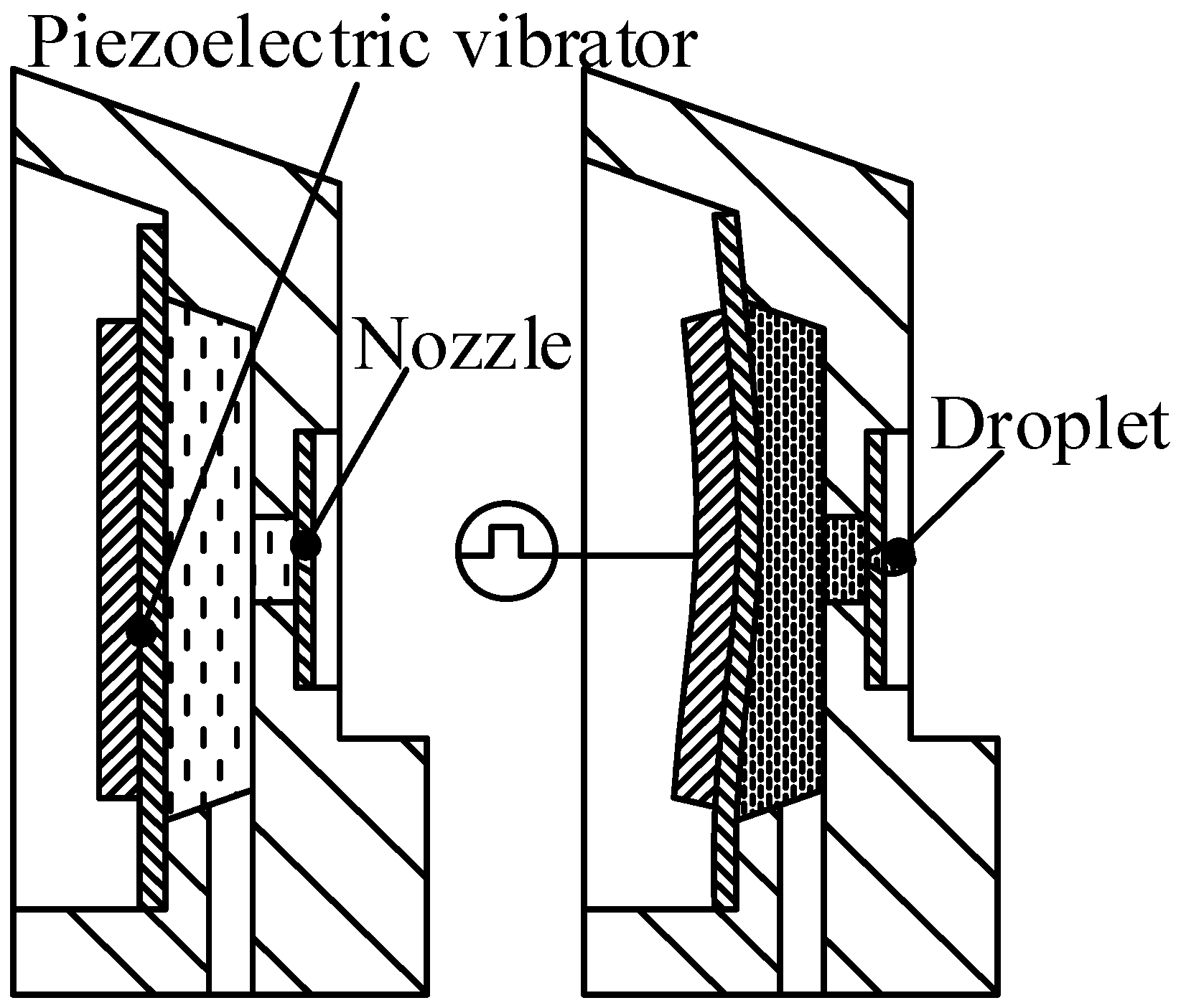
The structure of the piezoelectric micro-jet lubricating device, which was designed for this study, mainly consists of a piezoelectric vibrator and a nozzle, as shown in
Figure 1. The vibrator vibrates when pulse voltages are applied to it, while, at the same time, acoustic pressure waves are created and spread through the liquid in the cavity of the micro-jet, and droplets are jetted out of the cavity when the pressure waves spread to the nozzle. This is how the piezoelectric micro-jet works.
Figure 1.
The structure of the micro-jet.
Figure 1.
The structure of the micro-jet.
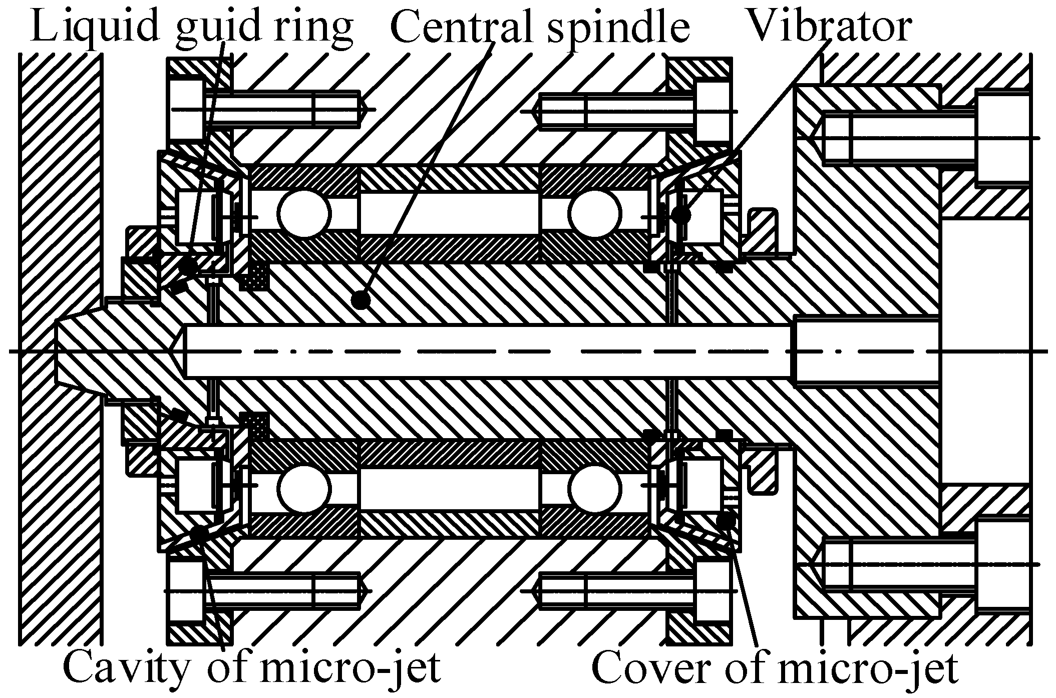
To realize the DOD lubrication of the gyroscope’s bearing system, we made full use of the space of the bearing system and embedded the piezoelectric micro-jets into it, as shown in
Figure 2. The embedding of the micro-jets cause no change to the overall volume. In order to provide lubricating oil to the cavity of the micro-jet and decrease the total mass of the system, the central spindle was desgined as a hollow craft to be the lubricating oil supply channel such that the lubricating oil is transported to the interior cavity of the micro-jets through the lubricating oil supply channel, and, when the bearing lubrication is insufficient, the droplets of the lubricating oil are sprayed out to the bearings by the pressure waves that are generated by the vibrators.
Figure 2.
The local structure of gyroscope after embedding the piezoelectric micro-jets.
Figure 2.
The local structure of gyroscope after embedding the piezoelectric micro-jets.
3. Simulation Settings
Because of the quick response time of the injection process of the micro-jets and the short forming time of the micro-droplets, it was difficult to analyze the characteristics of the droplets, such as the formation time, velocity, molding length and motion state, during the injection process under the existing experimental conditions. Therefore, it was necessary to carry out numerical simulations of the injection process of the droplets in order to analyze the performance of the injection.
3.1. The Finite Element Model
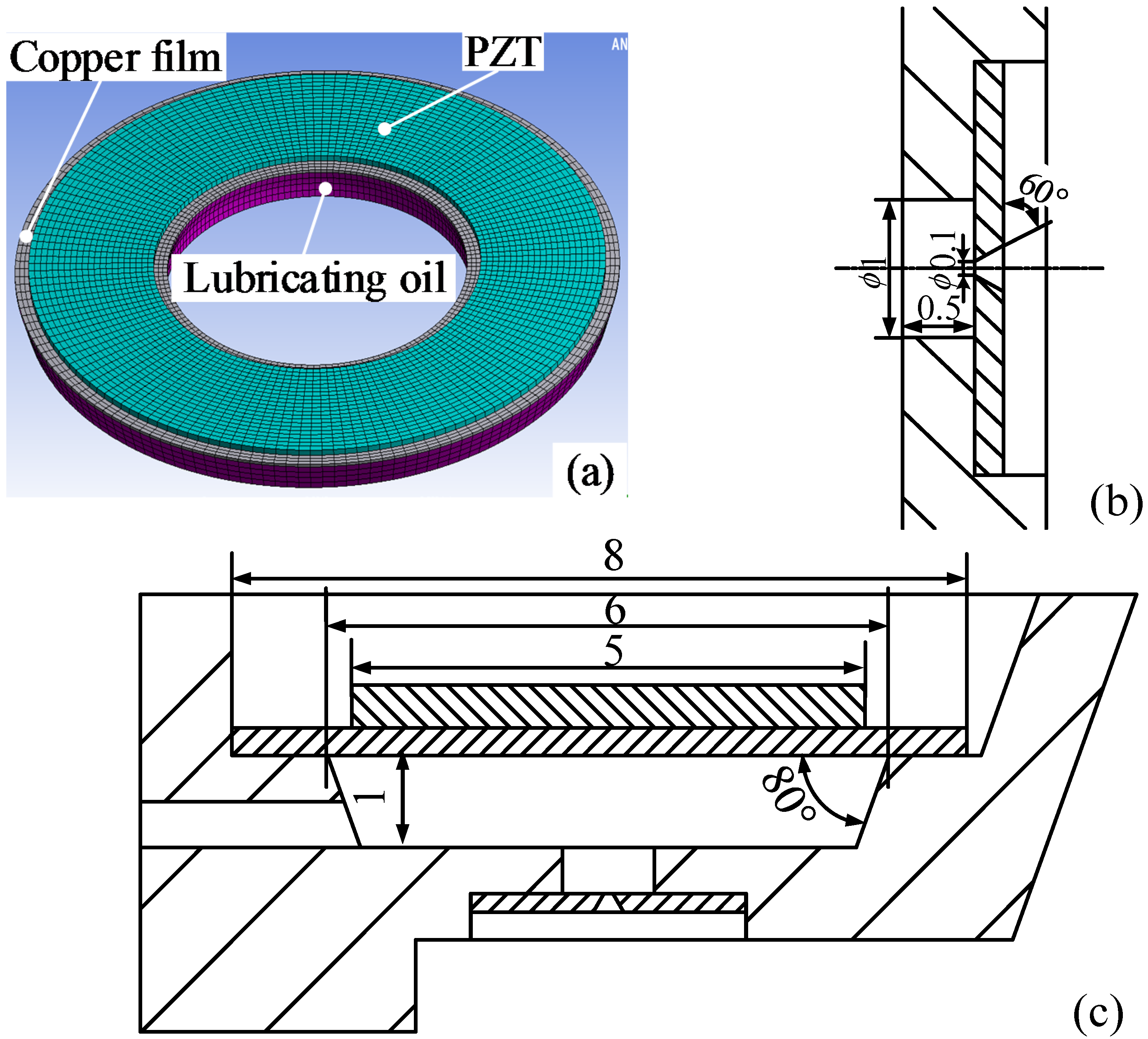
The piezoelectric vibrator was composed of piezoelectric ceramic and copper films; they were boned together and made as the two electrodes of the vibrator, respectively. The inner ring diameter of copper film and PZT were
mm and
mm, respectively. The whole finite element model of the micro-jet is shown in
Figure 3a, and, since the micro-jet is a rotating body, we have simplified it here into a two-dimensional model. The main dimension of each part of the micro-jet is shown in
Figure 3b,c.
Figure 3.
The model and main dimension of the micro-jet (unit: mm): (a) the whole finite element model; (b) the nozzle part; (c) the simplified two-dimensional model.
Figure 3.
The model and main dimension of the micro-jet (unit: mm): (a) the whole finite element model; (b) the nozzle part; (c) the simplified two-dimensional model.
3.2. The Simulation Setting
The most suitable working frequency and the displacement-time relations of particles were analyzed by the FEM software ANSYS. The density, elasticity modulus and Poisson ratio of the copper film were set at 7.5 × 10
3 kg/m
3, 7.65 × 10
10 N/m
2 and 0.32, respectively. The density and dynamic viscosity of the lubrication oil were set at 859 kg/m
3 and 8.91 × 10
−3 Pa·s. The material of the ceramic was PZT-5H, and the physical properties (elastic stiffness constant matrix [
cE], piezoelectric stress constant matrix [
e] and dielectric constant matrix [
εT]) of the PZT in the simulation were set as:
= Due to the existence of the FSI (fluid-structure interaction) effect in the simulation, the acoustic element Fluid30 was selected as the element type of lubrication oil part, while only the pressure DOF (degree of freedom) was maintained. The element type of the fluid-structure interface was set for Fluid30 with DOF of Ux, Uy, Uz, and the pressure maintained. The pressure boundary conditions of inlet and outlet of the micro-jet were all set at 0, and other constraints were set as its actual situation.
4. The Velocity-Inlet Boundary Conditions
In order to obtain the velocity-inlet boundary conditions for the injection simulations, we decided to get the volume change function of the cavity of the micro-jet first, which was caused by the vibration of the piezoelectric vibrator.
As we mainly focused on the injection performances of the micro-jet for simplicity's sake, the backward flow occurred at the inlet of ball-race contact, and the thermal balance in the bearing
etc., which had effects on the lubrication performances of the bearing, were not considered for this study. For details, please read the article by Mohammadpour
et al. [
15].
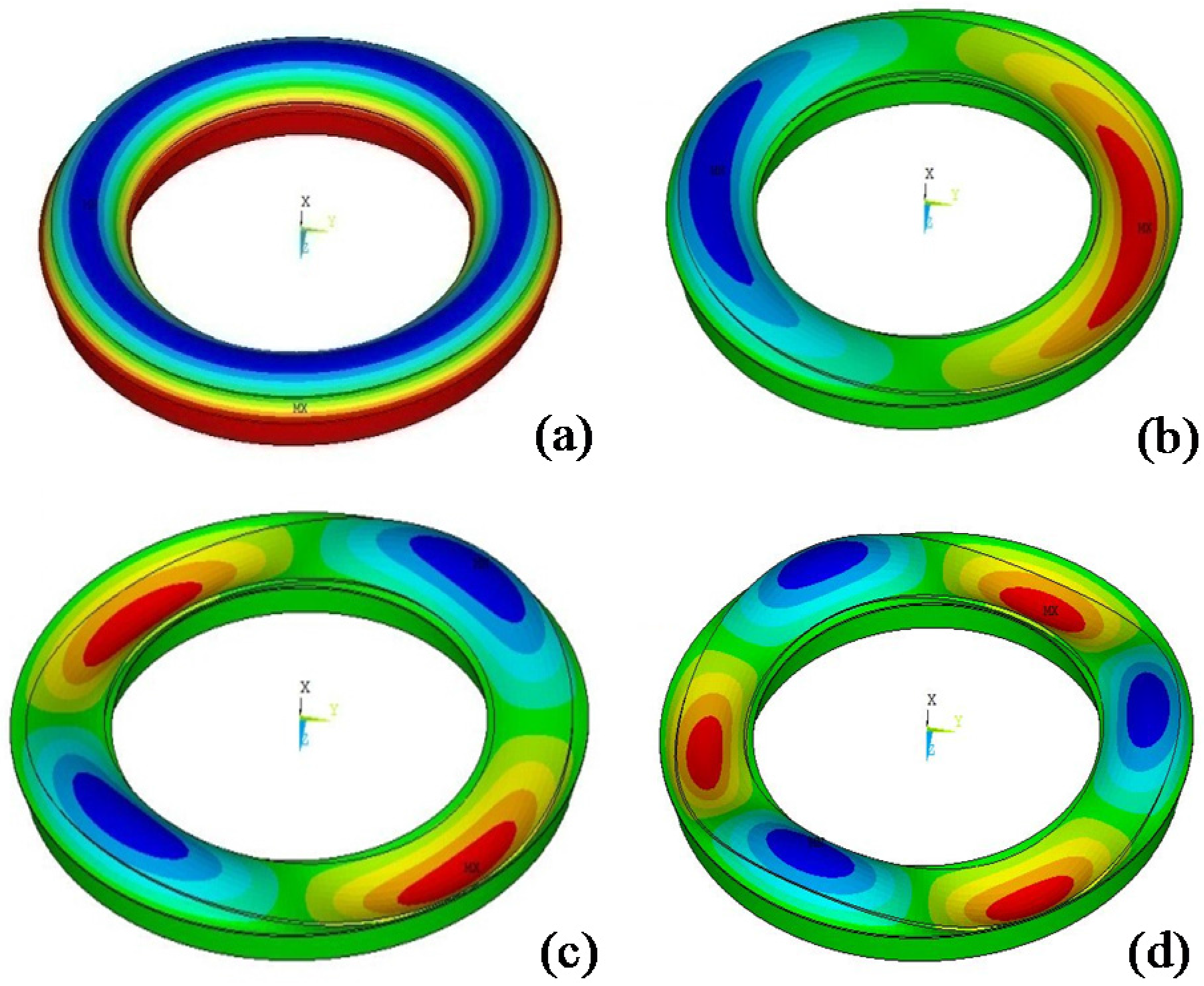
The first four mode shapes of the micro-jet are shown in
Figure 4; the corresponding resonant frequencies are 1.83 kHz, 4.32 kHz, 7.01 kHz and 9.49 kHz, respectively. The frequency of the first mode shape was preferable as the working frequency due to the central symmetrical characteristic, which can reduce the difficulty of the positioning when being assembled.
Figure 4.
The first four modes of vibration.
Figure 4.
The first four modes of vibration.
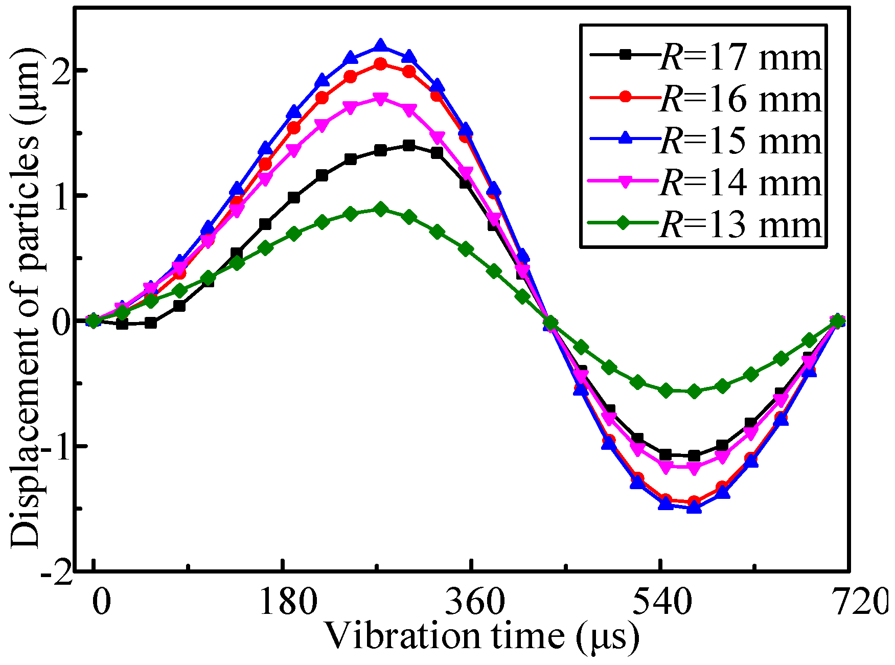
The displacement-time relation curves of particles with different radial positions on the fluid-structure interface were obtained, as shown in
Figure 5. The square pulse voltages were selected, as the excitations with the frequency and amplitude were set to 1.83 kHz and 100 V, respectively.
Figure 5.
The displacement-time relation curves of particles with different radial position on the fluid-structure interface (R is the radius of the particle’s position).
Figure 5.
The displacement-time relation curves of particles with different radial position on the fluid-structure interface (R is the radius of the particle’s position).
A numerical fitting model of a Fourier series function was adopted to fit the displacement-time relation curve of the particles with radius
R = 15 mm, in accordance with the data of
Figure 5, as shown in Equation (1). In the equation,
is the vibration frequency and
t represents the time. The fitting coefficients in the equation above are listed in
Table 1.
Table 1.
The coefficients of Equation (1).
Table 1.
The coefficients of Equation (1).
| n | an | bn | n | an | bn |
|---|
| 0 | 0.3456 | --- | 7 | −0.0204 | −0.0282 |
| 1 | −0.4588 | 1.5104 | 8 | −0.0180 | −0.0242 |
| 2 | 0.2656 | −0.4576 | 9 | −0.0203 | −0.0145 |
| 3 | 0.0208 | −0.0999 | 10 | −0.0211 | −0.0140 |
| 4 | −0.0034 | −0.0718 | 11 | −0.0183 | −0.0099 |
| 5 | −0.0069 | −0.0491 | 12 | −0.0217 | −0.0057 |
| 6 | −0.0122 | −0.0310 | 13 | −0.0211 | −0.0047 |
The fitting curve, which was determined by Equation (1), gives a better fit for the simulation data, as shown in
Figure 6.
Figure 6.
The fitting curve, which was determined by Equation (1).
Figure 6.
The fitting curve, which was determined by Equation (1).
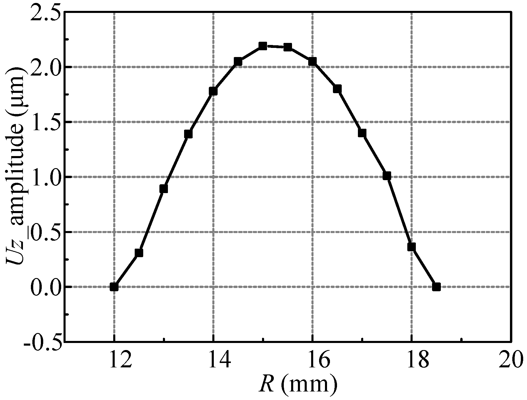
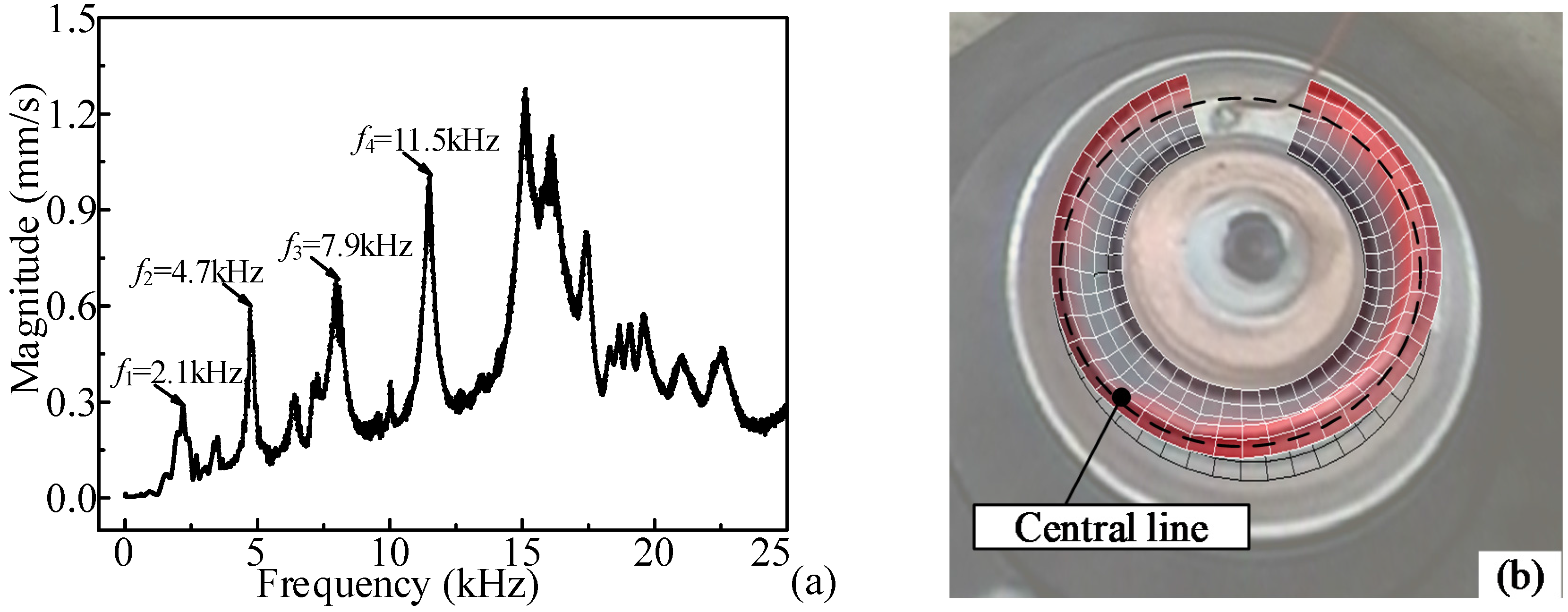
The relation curve of vibration amplitude and radial position of particles was obtained from
Figure 5, as shown in
Figure 7. As can be seen, the curve is approximately axially symmetric, and the symmetry axis is
R = 15 mm. Moreover, the vibration directions and frequencies of the particles are all the same. For convenience, we call the particles with radius
R = 15 mm “central line particles.”
Combined with Equation (1), the vibration displacement
of particles on the fluid-structure interface was deduced by fitting the curve in
Figure 7, as shown in Equation (2). In this equation,
r is the radial distance between particles and the central line particles,
is the vibration amplitude of the central line particles, and
is the effective radial width of the vibrator (here
). The fitting coefficients in Equation (2) are listed in
Table 2.
Figure 7.
The relation curve of vibration amplitude and radial position of particles.
Figure 7.
The relation curve of vibration amplitude and radial position of particles.
Table 2.
The coefficients of Equation (2).
Table 2.
The coefficients of Equation (2).
| n | cn | dn | n | cn | dn |
|---|
| 0 | 1.2439 | --- | 4 | −0.0076 | −0.0052 |
| 1 | −1.0628 | 0.2669 | 5 | −0.0042 | −0.0233 |
| 2 | −0.1473 | 0.0921 | 6 | 0.0060 | −0.0200 |
| 3 | −0.0326 | 0.0263 | | | |
The volume change of the cavity
was deduced, as shown in Equation (3), where
is the radius of the central line particles.
Then, the mean volume flow of the inlet of single nozzle was calculated with Equation (4):
Therefore, the inlet velocity boundary conditions of the single nozzle is:
5. The Injection Performance of the Nozzle
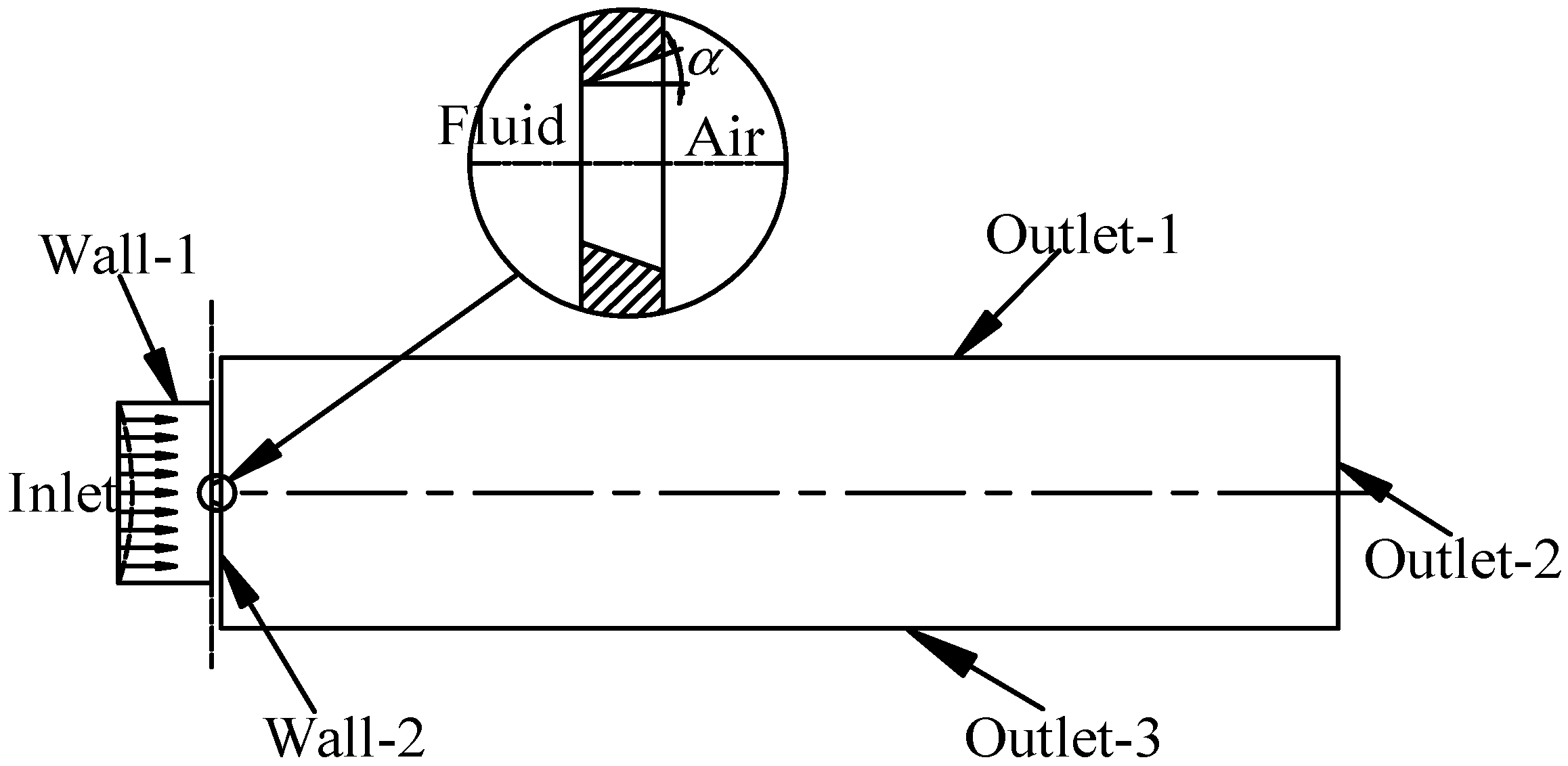
In order to get the injection performance of the nozzle under single-pulse voltage, we utlized CFD simulation software (CFD-ACE+, ESI Group) to analyze the forming and moving stages of the droplets. According to the models and dimensions shown in
Figure 3, the injection model of the nozzle was simplified in the simulation, as shown in
Figure 8.
Figure 8.
The injection model of the nozzle.
Figure 8.
The injection model of the nozzle.
The left and right sides of the nozzle were set as fluid- and air-field respectively, and the divergence angle
is set at 30° to correspond to the dimensions in
Figure 3b. The inner wall of the cavity, Wall-1, is half-hydrophilic, and the contact angle was set at 85°. The air-liquid interface, Wall-2, is hydrophobic, and the contact angle was set at 165°. The velocity-inlet boundary conditions were set in accordance with Equation (5), and others were all set to have no slip boundaries. The density and dynamic velocity of the air were set at 1.1614 kg/m
3 and 1.846 × 10
−3 respectively, and the surface tension of the lubricating oil was set at 0.0725 N/m. The temperature was set at 20°, ignoring the influence of gravity. The structured quadrilateral cell was selected in this gas-liquid two-phase flow model, and the analysis type was set to have transient analysis.
In order to improve the uniformity of the lubrication of the bearing, we decided to make the droplets dispersed into a plurality of small droplets, and the smaller the droplets were, the better. The total time used for an ejected droplet from the initial formation to travel completely outside of the nozzle affected the response time of the lubrication, and we called this the "molding time" of the droplets. We also decided that the droplets’ molding time should be decreased and that velocity should be increased so as to reduce the response time of the bearing lubricating time. Furthermore, we called the length of the droplet at the end of the molding time the "molding length" of the droplet, determining the minimum effective working distance between the nozzle and the bearing.
Thus, the influences of the voltage pluses on the molding time, velocity, molding length, and dispersion condition of the droplets were analyzed. The major parameters of the pulse voltages were amplitude, duty ratio and frequency, and, since the working frequency was limited by the structure and lubricating oil properties, only the first two parameters’ influences were analyzed.
5.1. The Influence of the Amplitude
Setting the duty ratio at 50%, and keeping the properties of the lubricating oil unchanged, pulse voltages with different amplitudes were applied to the piezoelectric vibrator. The velocity-inlet boundary conditions were obtained by Equation (5) and then applied to the injection modal.
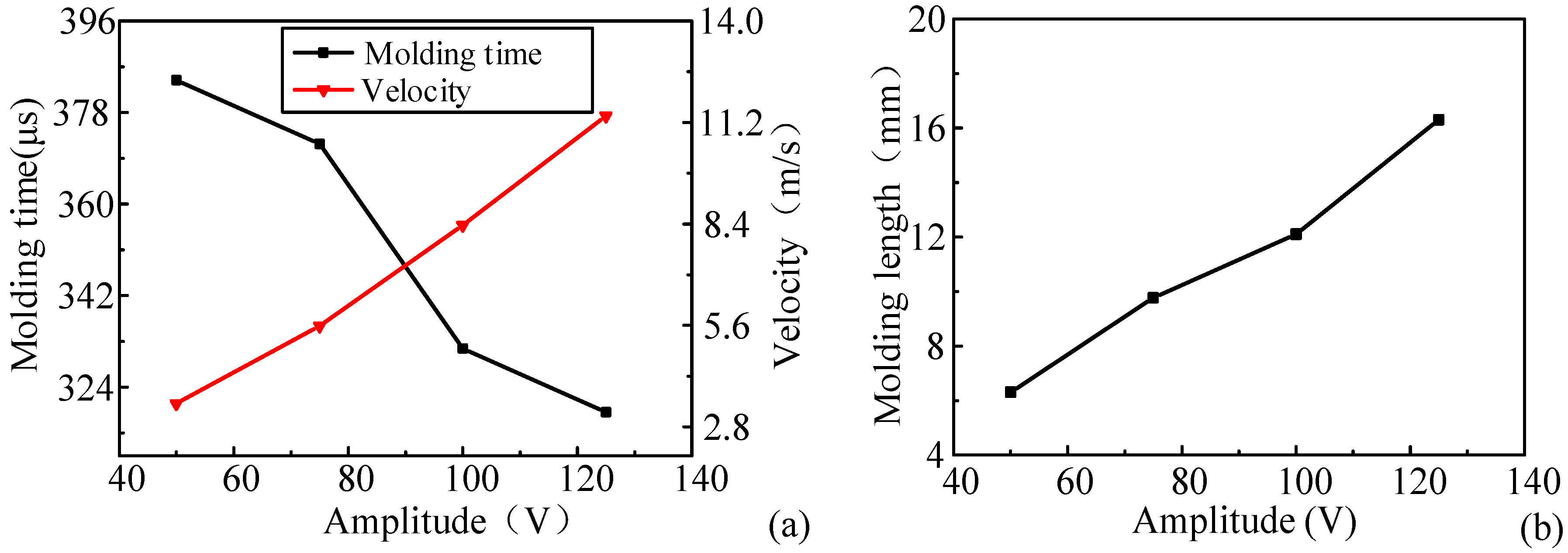
The changing curves of molding time and velocity corresponding to different amplitudes of the pulse voltage are shown in
Figure 9a. As can be seen, with the increase of the voltage amplitude, the molding time decreased and the velocity increased gradually. Thus, we decided that, for a quick response to the lubrication, the amplitude of the pulse voltages should be raised to a certain range.
The relationship curve of molding length and amplitude was obtained, as shown in
Figure 9b. It appears that the molding length rose with the increase of the amplitude of the pulse voltages. Therefore, when increasing the amplitude of the pulse voltages, we decided to assure that the molding length was shorter than the distance between the nozzle and the bearing.
Figure 9.
(a) The changing curves of molding time and velocity; (b) the relationship curve of molding length and amplitude.
Figure 9.
(a) The changing curves of molding time and velocity; (b) the relationship curve of molding length and amplitude.
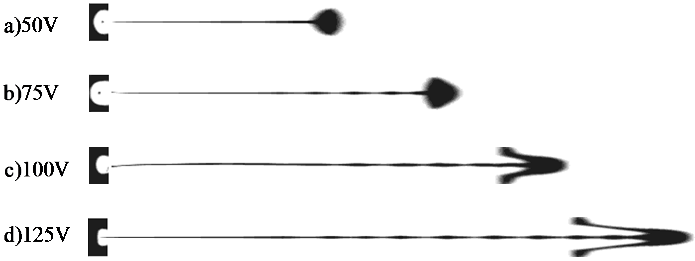
The dispersion conditions of the droplets with different amplitudes of pulse voltages are shown in
Figure 10. It can be seen that, when the voltage amplitude was relatively low, the shape of the droplet was regular and roughly spherical, and, with the increase of the voltage amplitude, the droplet was gradually dispersed; the larger the voltage, the higher the degree of divergence. Thus, in order to achieve sufficient lubrication, we decided that a larger amplitude of the pulse voltages should be selected in a certain range.
Figure 10.
The dispersion conditions of the droplets with different amplitudes.
Figure 10.
The dispersion conditions of the droplets with different amplitudes.
5.2. The Influence of the Duty Ratio
Keeping the amplitude of the pulse voltages at 100 V, the impact of duty ratio on the injection performance was analyzed by changing the ratio size. As before, Equation (5) was used to calculate the velocity-inlet boundary conditions that were applied to the injection modal. To be clear, the duty ratio was set to 1 in the results instead of 0.999 for convenience.
The changing curves of molding time and velocity under pulse voltages with different duty ratios are shown in
Figure 11a. The figure demonstrates that the velocity reduced along with the increase of the duty ratio, while the molding time gradually increased. Therefore, we concluded that, in a certain range, the duty ratio of the pulse voltages should be raised so as to improve the response time of the lubrication.
The relationship curve of the molding length and duty ratio was obtained, as shown in
Figure 11b. As we can see, with the increase of the duty ratio of the pulse voltages, the molding length rose gradually.
Figure 11b has a guiding role for determining the minimum distance between the bearing and the nozzle when different duty ratios are selected.
Figure 11.
(a) The changing curves of molding time and velocity; (b) the relationship curve of molding length and duty ratio.
Figure 11.
(a) The changing curves of molding time and velocity; (b) the relationship curve of molding length and duty ratio.
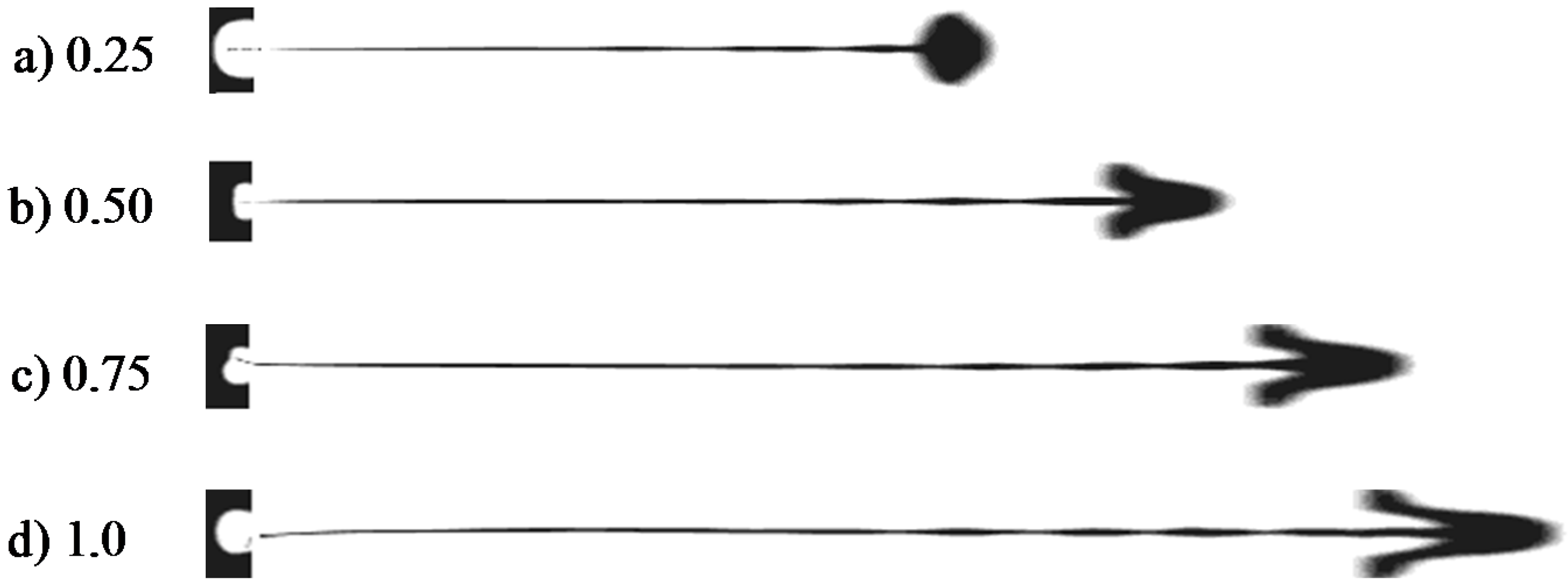
The dispersion conditions of the droplets with different duty ratios of pulse voltages are shown in
Figure 12. The figure shows that the droplet is roughly one spherical drop when relatively low duty ratio is applied, and the level of the dispersion increases with the increase of the duty ratio. Therefore, we concluded that, for achieving sufficient lubrication, a larger duty ratio should be selected if conditions are met.
Figure 12.
The dispersion conditions of the droplets with different duty ratio.
Figure 12.
The dispersion conditions of the droplets with different duty ratio.
7. Conclusions
A novel piezoelectric micro-jet was designed and embedded in the bearing system to supply the DOD lubrication. The mathematic model of velocity-inlet boundary conditions was deduced and applied to the injection performance simulations to analyze the deformations and motion states of the droplets, which could not be measured and observed through experiments. The molding time, velocity, molding length, and dispersion condition of the droplets under different pulse voltages were analyzed, and, to obtain better performance of the micro-jet, the appropriate excitation parameters were given in accordance with the simulation results.
The actual working frequency and injection states of the micro-jet under different excitations were obtained by the experiments and the volumes of the droplets were calculated. The experiments proved that the piezoelectric micro-jet lubricating system can work effectively and that the methods of adjusting the injection performance to meet different requirements are given according to the analysis of the experimental results.
The validity of the mathematic model of velocity-inlet boundary conditions was confirmed through the comparison between simulations and experiments; thus, the injection performance of the micro-jet can be predicted by the injection simulation method described in this paper. In conclusion, this paper provides an effective solution to the problem of bearing lubrication.
Based on this, we will carry out complete multiple physical field coupling simulations and experimental validations of the coupled model in future studies so that the injection performance of the micro-jet for lubrication can be further analyzed.


