Article

Microporous Titanium through Metal Injection Moulding of Coarse Powder and Surface Modification by Plasma Oxidation

by
Mohammed Menhal Shbeh
1,2,*,
Aleksey Yerokhin
3,4 and
Russell Goodall
1
1
Department of Materials Science and Engineering, University of Sheffield, Sir Robert Hadfield Building, Mappin Street, Sheffield S1 3JD, UK
2
Department of Production Engineering and Metallurgy, University of Technology, Al-Sinaa’ Street, Baghdad 10066, Iraq
3
School of Materials, University of Manchester, Manchester M13 9PL, UK
4
National University of Science and Technology “MISIS”, Leninsky Prospect 4, Moscow 119049, Russia
*
Author to whom correspondence should be addressed.
Appl. Sci. 2017, 7(1), 105; https://doi.org/10.3390/app7010105
Submission received: 7 December 2016 / Revised: 12 January 2017 / Accepted: 16 January 2017 / Published: 22 January 2017
(This article belongs to the Special Issue Powder Injection Moulding)

Abstract

:
Titanium is one of the most attractive materials for biomedical applications due to having excellent biocompatibility accompanied by good corrosion resistance. One popular processing technique for Ti is Metal Injection Moulding (MIM). However, there are several issues associated with the use of this technique, such as the high cost of the fine powder used, the high level of contamination and consequent alteration to material properties, as well as the large volume shrinkage that occurs during sintering. In this study, the use of a relatively coarse Ti powder with a mean particle size of 75 μm to process Ti parts with the potential for biomedical applications by MIM will be examined, compared to a commercial Ti feedstock, and subsequently coated using Plasma Electrolytic Oxidation (PEO). The results show that samples produced with the coarse powder shrink 35% less and have a relative density 14% less with an average pore size three-times larger than that of the commercial feedstock. This helps increase the potential competitiveness of MIM in the production of biomedical parts, as it reduces cost, shrinkage and results in more intentionally-induced micropores, such as are desired for biomedical implants. PEO treatment of the samples yields a thick rough coating comprised of a mixture of rutile and anatase with interconnected microporous channels and openings resembling the mouth of a volcanic crater.

1. Introduction

Metal Injection Moulding (MIM) is a very well-known mass production technique for the processing of small to medium-sized metal parts with intricate shapes. It offers several advantages over other manufacturing processes, such as flexibility in design with minimal finishing operations, as well as reduced material waste [1]. These advantages have made MIM one of the most investigated processes for producing titanium parts, especially for biomedical applications. However, there are many obstacles towards the use of such technique in preparing Ti parts, such as the high cost of the fine powders used in the preparation of feedstock [2]. Another obstacle is the high reactivity of titanium at a relatively high temperature, where it reacts with the decomposed product of the binder during thermal debinding and sintering, resulting in high interstitial content [3]. Generally, powders with a particle size below 45 μm are used in injection moulding in order to result in minimal porosity within the samples and a density near the theoretical density for improved mechanical properties [4]. However, the smaller the particle size, the higher the surface area and the more the Ti part is prone to contamination and oxygen pick up during processing, debinding and sintering. In addition, the use of fine powders can result in more shrinkage, as the smaller the particles used, the greater the rate of sintering or the rate at which bonding between the particles, neck formation and growth (as well as densification) occur [5]. One way to reduce this shrinkage and the extent of contamination, as well as lower the cost, is to use Ti powder with a relatively coarse particle size (>45 μm). This will not only be more economical, but can also result in more intentionally-induced micropores. These micropores are advantageous, particularly for biomedical applications, where they promote bone ingrowth and cell attachment [6,7]. Aside from promoting bone-implant integration, the presence of these pores can also play a significant role in reducing the stiffness of the Ti parts to match that of the bone in order to avoid the stress shielding phenomenon [8,9]. Nevertheless, wear of the tools could be an issue in using coarse powders. Maetzig and Walcher [10] studied the possibility of using coarse powders for MIM with particles as large as 62 μm and concluded that it is possible to process them with reduced wear provided that an increased clearance was left between the bushing and the barrel. However, they did not report any details about the powders’ rheological and shrinkage behaviour after sintering.
The main aim of this study is to explore the use of a relatively coarse Ti powder to produce Ti parts by MIM with the potential for biomedical applications and compare it in terms of performance to a commercial Ti feedstock PolyMIM Grade 2. In addition, the rheological behaviour of both feedstocks and their volume shrinkage will be examined. Furthermore, the possibility of coating these Ti parts with amorphous ceramic coating using the plasma oxidation process will be explored in order to improve the bioactivity of the samples and result in accelerated cell-surface interlocking, as the Ti itself is bio-inert [11].

2. Materials and Methods

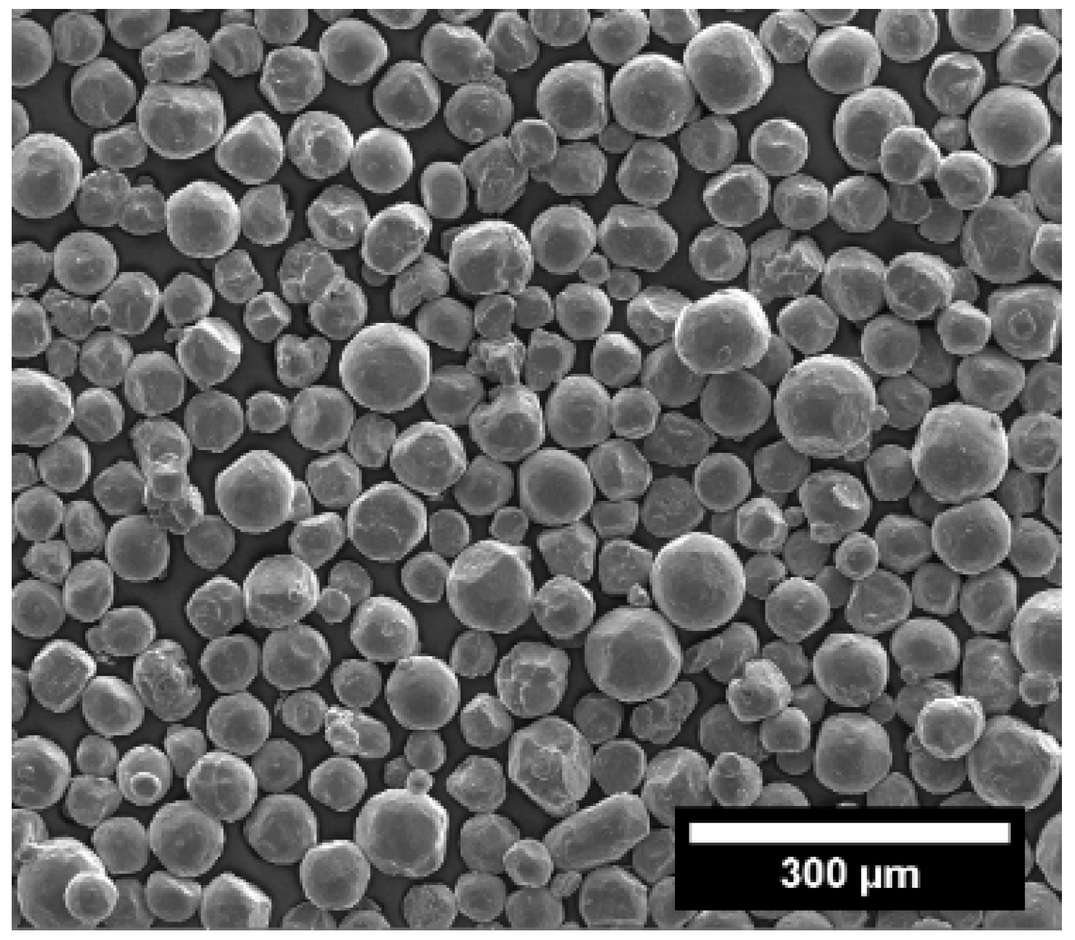
2.1. Preparation of Feedstocks

A relatively coarse spherical Ti powder Grade 2 (Arcam, Mölndal, Sweden) with a mean particle size of about 75 μm (as shown in Figure 1) was used in preparing a feedstock with a 58 vol. % solid content by mixing it with a three-component polymeric binder. The first part of the binder (the low viscosity part) was Polyethylene Glycol (PEG) 1500, and it constituted 70 vol. % of the total binder. PEG was chosen due to its availability, as well its good solubility in the water. The second part of the binder (the high viscosity part) was Poly Methyl Methacrylate (PMMA), and it comprised 25 vol. % of the binder. PMMA was chosen due to its high strength in comparison with other common polymers used in MIM, such as low and high density polyethylene, so that green samples can be easily handled after removal of PEG without any sample collapse [12]. Stearic Acid (SA) was the third part, which constituted 5 vol. % of the total binder (added as a lubricant). The mixing process of the powders was carried out in a high speed centrifugal mixer in a similar manner to our previous experiments using Speedmixer 800 FZ (Hauschild; Synergy Devices Ltd., High Wycombe, UK) [13]. The feedstock prepared was extruded twice using a vertical plunger-type injection moulder at a temperature of 150 °C and pressure of 45 MPa and subsequently pelleted into small pellets to be ready for injection. The commercial Ti feedstock used in this study was PolyMIM Grade 2 supplied by PolyMIM® Germany.

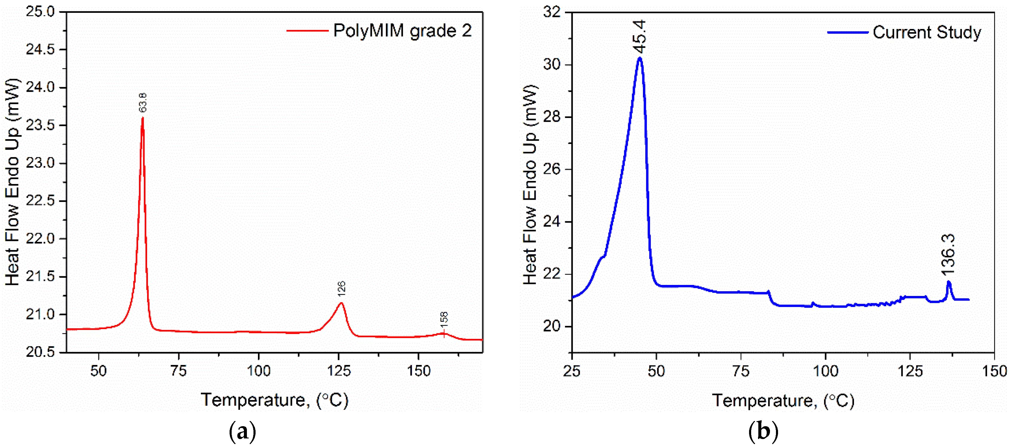
2.2. Differential Scanning Calorimetry Analysis of the Binders

DSC analysis was carried out using a Pyris 6 DSC (PerkinElmer, Waltham, MA, USA), in order to identify the peak melting temperatures of both commercial and prepared feedstocks and analyse their melting behaviour. The outcome of such analysis can be beneficial in facilitating the process of choosing the optimum extrusion and injection temperatures for the feedstocks prepared. Several samples of each feedstock were heated up to a maximum temperature of 200 °C at a rate of 10 °C/min.

2.3. Rheological Tests of the Feedstocks

Feedstock viscosity is one of the important parameters that needs to be evaluated in order to assess the suitability of feedstocks for injection moulding. The viscosity needs to be within a certain range in order for the feedstock to be successfully injection moulded, which is below 1000 Pa.s in the shear rate range of 102–105 s−1 [14]. The viscosities of both commercial and prepared feedstocks were analysed using a twin bore barrel capillary rheometer (Rosand RH2000, Malvern, UK) with a capillary die that has a diameter of 2 mm and a height of 16 mm. Rabinowitsch correction was applied in order to obtain the corrected shear rate. It should be noted that the commercial feedstock could not be tested at a temperature below 170 °C, as the capillary die of the rheometer became clogged below this temperature. This is expected, as it is recommended in the specification sheet of the PolyMIM feedstock to mix and inject the feedstock at a minimum temperature of 178 °C. Hence, the viscosity of commercial feedstock was tested at three different temperatures, namely 170, 185 and 195 °C, whereas the feedstock prepared in this study with the relatively coarse Ti powder was tested at 120, 135 and 150 °C due to its lower viscosity. The flow behaviour indices were estimated for both feedstocks using the following equation:
η = K γ ˙ ( n 1 )
where η is the viscosity, K is a constant, γ ˙ is the shear rate and n is the flow behaviour index (shear sensitivity). For non-Newtonian fluids with shear thinning behaviour, the shear sensitivity value is below 1, while for Newtonian fluids, it is equal to 1. Another critical variable in assessing the capability of the feedstock to take the shape of the mould cavity is the yield shear stress. Yield shear stress is the minimum stress required to cause the feedstock to flow, below which no flow occurs. The yield stresses for both feedstocks were calculated via the Bingham model using the following equation [15]:
τ = τ y + η p γ ˙
where τ y is the yield shear stress and η p is the plastic viscosity.

2.4. Sample Preparation and Sintering

A vertical plunger-type injection moulder composed of hydraulic injection piston with no plasticizing screw (J.B. Engineering, Chippenham, UK) was used to injection mould small cylindrical parts of both feedstocks at a pressure of 45 MPa. The commercial feedstock was injection moulded at a temperature of 185 °C into small cylindrical parts with a diameter of 10 mm and a height of approximately 13.50 mm. The mould was heated to 60 °C in order to facilitate the process of filling the cavity of the mould. It should be noted that great difficulty was encountered during moulding at a lower mould temperature, where the feedstock either freezes before reaching the mould cavity or partially fills it before freezing, resulting in an incomplete part. Another batch of commercial feedstock samples was made using an Arburg 320 all-rounder at a pressure of 1400 bar and a temperature of 195 °C with a dosage volume of 10 cm3 for comparison purposes. In contrast, the feedstock prepared by this study was injection moulded using the vertical plunger-type injection moulder at a temperature of 150 °C into cylindrical samples without the need to heat the mould. Some green samples of both feedstocks were broken and their surfaces were characterized using Scanning Electron Microscopy (SEM). The average particle size for the Ti powder used in commercial feedstock was determined by estimating the average size of spheres with equivalent volume to that of Ti particles, which were observed in six SEM images for the commercial feedstock [16].
Parts were water debound at a temperature of 50 °C in a water tank filled with distilled water for 35 h. Next, the parts were taken out of the tank and dried for 2 h at 100 °C in order to remove the moisture. After that, the samples were sintered at 1320 °C for 2 h under the flow of argon. Volume shrinkages after debinding and sintering of the samples were monitored by measuring the dimensions of the samples using a Vernier Caliper with a resolution of 0.01 mm. Samples were analysed for contamination by using a LECO melt extraction system by AMG Analytical, Rotherham, UK. The final densities of the samples were measured using a helium pycnometer with a filling pressure of 10 psi over 10 cycles.

2.5. Microstructural and Mechanical Analyses of the Samples

Samples were ground until they were a plane using Struers MD-Mezzo 120 Disc followed by MD-Largo with a diamond suspension of 9 μm before finishing with Struers chemo-textile cloth using a solution of colloidal silica plus 30% hydrogen peroxide. The average pore diameter for the samples sintered from each feedstock, as well as their degree of roundness was determined using image analysis software (ImageJ, a public domain Java image processing program, www.imagej.nih.gov) by binarizing the images and measuring pore diameters using minimum and maximum Feret diameters and then averaging them. Samples with a height of around 12.4 ± 0.7 mm from both feedstocks were tested under compression loading at a strain rate of 0.001 s−1 and a maximum load of 40 KN using a Zwick Z50 testing machine (Zwick Roell, Ulm, Germany). The yield strength for the samples was estimated using the 0.2% offset method.

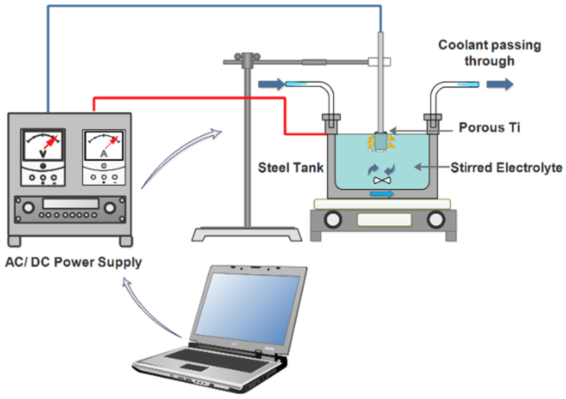
2.6. Plasma Electrolytic Oxidation of Samples

MIM samples produced using the coarse Ti powder were tap threaded, ultrasonically cleaned in acetone for 10 min and dried. The samples were then bolted into a Ti bar with external insulation connected to the positive output of the power supply, while the water-cooled steel tank was connected to the negative output, as shown in Figure 2. The Plasma Electrolytic Oxidation (PEO) treatment of the samples was carried out in a potentiodynamic DC mode to a maximum voltage of 500 V at the scan rates of 2.10 and 1.05 V·s−1 corresponding to the total treatment time of 4 and 8 min, respectively. The electrolytic solution used in the process was composed of 14 g·L−1 disodium hydrogen phosphate (Na2HPO4) in distilled water. The PEO treated samples were rinsed and dried. The samples with coatings were imaged and analysed using Scanning Electron Microscopy (SEM) Inspect F (FEI, Hillsboro, OR, USA). In addition, X-ray Diffraction (XRD) analysis was used to examine the surface phase composition (D2 PHASER, Bruker, Billerica, MA, USA).

3. Results

3.1. DSC Analysis Results

The results of the DSC analyses for both of the commercial and developed feedstocks are plotted in Figure 3. It was found that the first part of the binder for the commercial feedstock had a higher peak melting temperature of about 64 °C compared to that used in the current study (PEG 1500), which was approximately 45 °C, whereas the second part of the binder for commercial feedstock had a lower peak melting temperature of about 126 °C than that of the current feedstock, which was about 136 °C. A small third peak was also noted at about 158 °C in the commercial feedstock, which might indicate that there is a third polymeric component in the commercial feedstock. It should be noted that the DSC test for the commercial feedstock has been repeated three times to make sure that consistent data were obtained. Auzène et al. [17] investigated the use of different commercial feedstocks including 316L stainless steel PolyMIM and reported that the feedstock had a similar infrared spectrum to polypropylene, though they have not reported their findings in detail. One might argue that the second part of the binder for commercial feedstock is actually high density polyethylene, as the peak melting temperature lies in the peak melting temperature range for high density polyethylene, which is about (125.8–138 °C) [18]. In addition, the small third peak could correspond to the peak melting temperature of the isotactic polypropylene which ranges from 160 to 166 °C [19].
In order to investigate this further, an FTIR test (Fourier Transform Infrared Spectroscopy) was carried out in the wavelength range from 4000 to 400 cm−1 with a sampling number of 16 times. The result of the test is shown in Figure 4.
The obtained data were compared with the results in the literature, and it was found that several peaks coincide with the high density polyethylene peaks reported by Kumar and Singh, as shown in Table 1 [20] from work on the recovery of hydrocarbons from high density polyethylene waste. Other peaks could not be explained due to the complexity of the binder system used, which makes the analysis process more challenging.

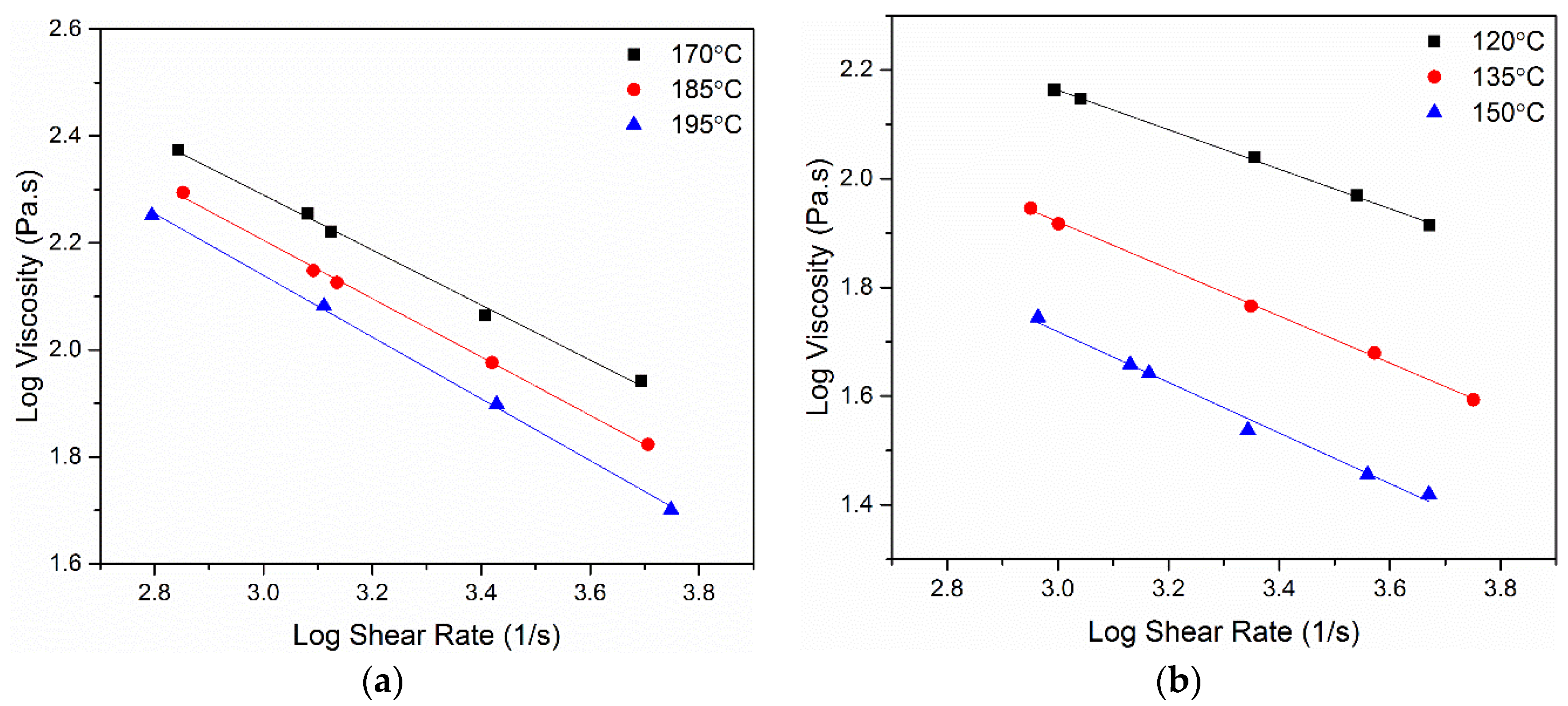
3.2. Rheological Analysis Results

Rheograms of both commercial and current feedstocks are shown in Figure 5.
It can be seen from Figure 5 that the viscosity of the commercial feedstock is much higher than that of the feedstock used in the current study, which means that higher injection and tool temperatures are needed in order to successfully inject the samples into the desired shapes. Both of the feedstocks showed some shear thinning behaviour, which is desired in the MIM industry, especially for intricate parts. The yield shear stresses, as well as the flow behaviour indices for both feedstocks are summarized in Table 2. Although the commercial feedstock was tested at much higher temperatures (as required by its higher viscosity), it was found that it has a much higher yield stress than that of the current feedstock and has a lower flow behaviour index.

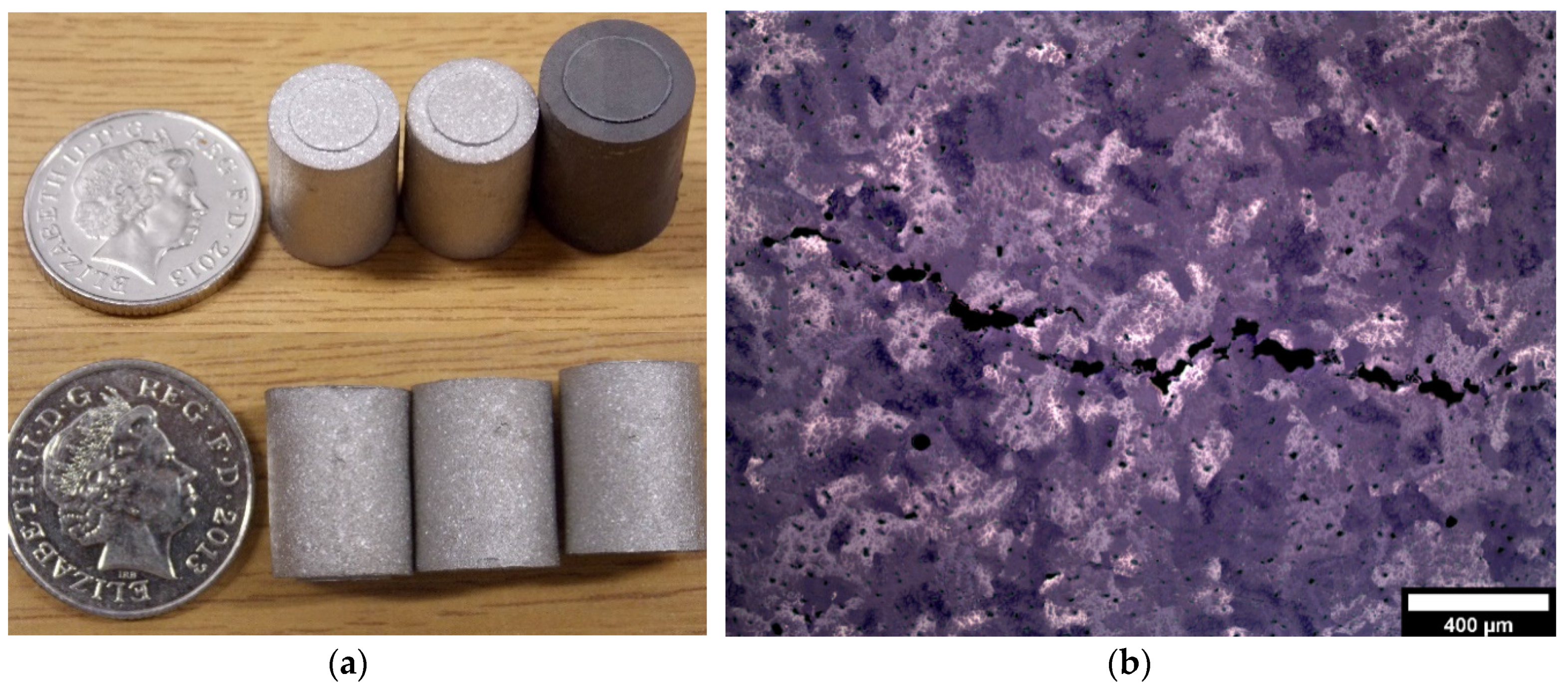
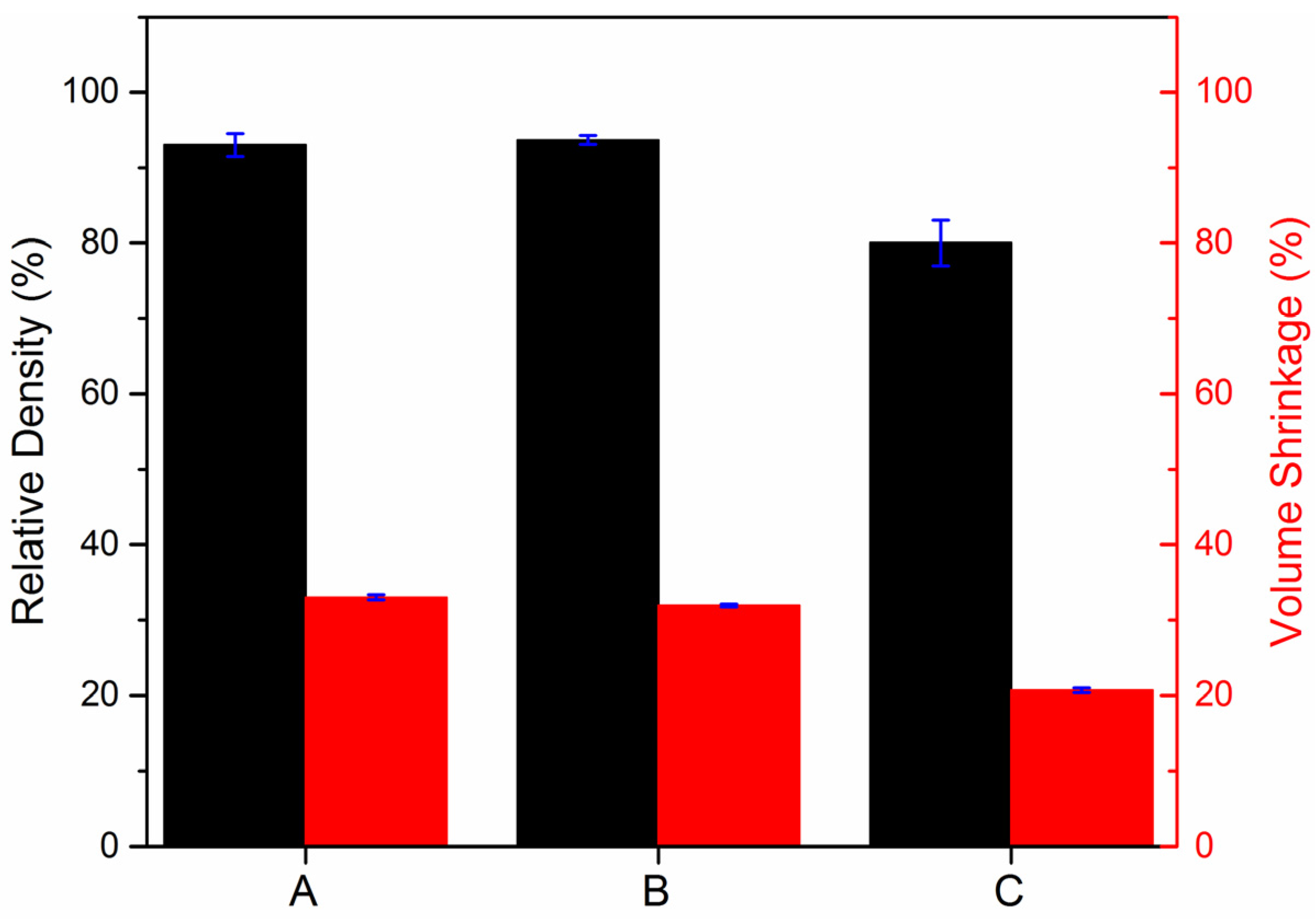
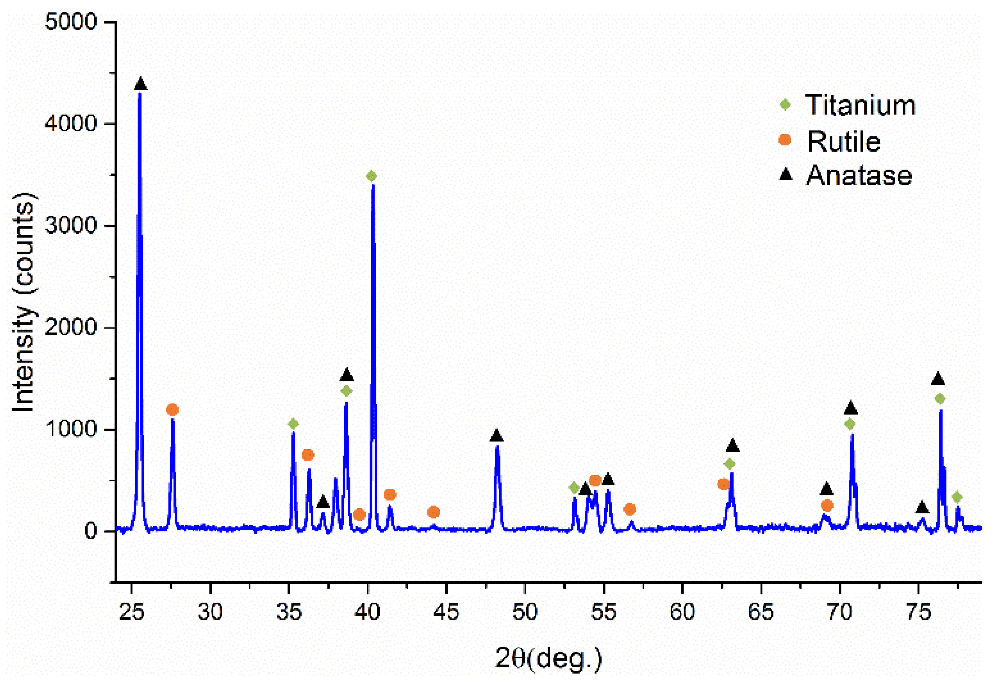
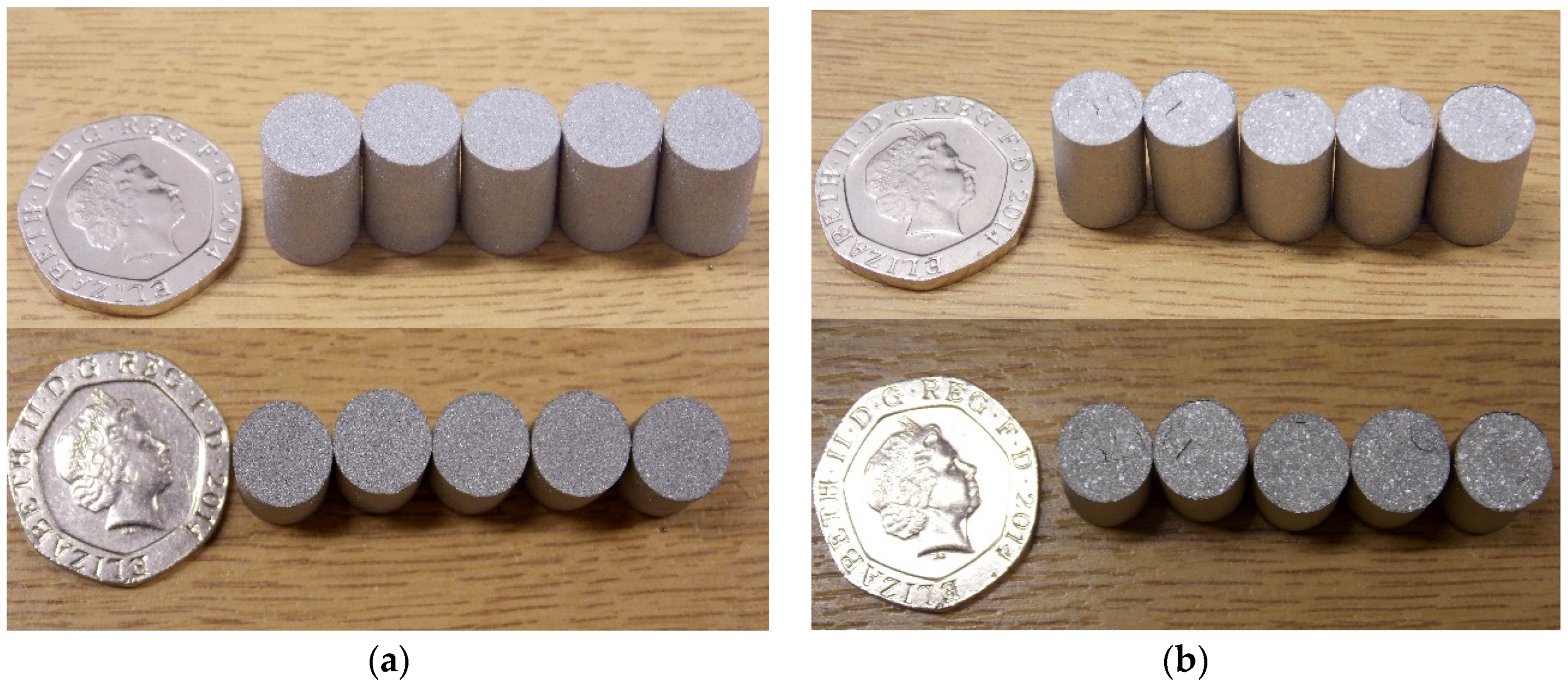
3.3. Structural Characterisation of Green and Sintered Samples

The surface of as-broken samples from both feedstocks are shown in Figure 6.
It can be observed that the Ti powder used in the commercial feedstock is spherical and therefore a high probability that it is a gas atomized powder with good packing density. The sizes of its particles were analysed on several images using image analysis software and found to range from 12 to 45 μm, with an average particle size of about 23 μm. It was also noted that the Ti particles were coated with a layer of what is believed to be polyethylene, referring to the large amount of the second part of the binder in the commercial feedstock. In comparison, the relatively coarse Ti particles used in the current study were surrounded by the binder, consisting of PEG with some PMMA.
Images of the sintered parts from both feedstocks are shown in Figure 7. It was noted that samples made with the commercial feedstock using the vertical plunger-type injection moulder had some cracks on the surface of the samples. These cracks might be due to the insufficient injection and backing pressure of the injection moulder used to mould the commercial feedstock properly, as the commercial feedstock had a much higher yield shear stress than that developed here; thus, it requires being processed and moulded at a much higher temperature and pressure. Nevertheless, commercial feedstock samples made using the Arburg 320 all-rounder did also have small cracks, but less apparent than the ones seen on samples made using the vertical plunger-type injection moulder. Some of the sintered samples are shown in Figure 8.
It was also noted that the majority of the samples had small crater-like defects at the surface and some blistering. These craters are believed to be formed due to the thermal decomposition and diffusion of the high viscosity part of the binder from the inside of the sample through the surface during the initial stages of the sintering cycle, leaving a small volcano-like blister with crater-like features. The relative densities and volume shrinkages of the samples after sintering are shown in Figure 9.
It can be seen that samples made using current study feedstock with the coarse Ti powder had a lower relative density than those made from commercial feedstock PolyMIM with the fine powder, and consequently higher porosity. This can be attributed to the size of the titanium powder used in this study compared to the commercial feedstock, where finer particles sinter at a much higher rate, resulting in greater growth of the necks and spheroidization of pores compared to coarser particles. However, the volume shrinkage after sintering for the samples made by commercial feedstock was found to be much greater than that of the samples made by the current study, where samples processed with the coarse powder shrank 20.7% in volume, while samples made of commercial feedstock shrank 32%–33% in volume. Owing to the fact that the sintering process is mainly driven by the surface free energy of the powder, the higher the surface area of the powder, the greater the rate of sintering, resulting in more volume shrinkage in the samples [22]. Although the solid content for the commercial feedstock (which can have an impact on the volume shrinkage) is not known, generally the solid content for such fine powders in commercial feedstocks ranges from 60% to 65%. It can also be noticed that the standard deviation for the volume shrinkage after sintering for the samples made by the commercial feedstock using the Arburg injection moulder was the lowest (about 0.18 compared to the samples made by the current study feedstock using the vertical plunger-type injection moulder of about 0.31). In comparison, the standard deviation for samples made by commercial feedstock using the vertical plunger-type injection moulder was 0.35. These differences in shrinkage and standard deviation between samples made by the vertical plunger-type injection moulder and the ones produced by the Arburg 320 could be a consequence of the high backing and injection pressure used in the Arburg compared to the vertical plunger-type injection moulder; the pressure used in the Arburg was more than triple that used in the vertical plunger-type injection moulder.
The extent of contamination in the sintered samples with interstitial elements is summarized in Table 3.
It can be observed that the carbon concentration in the parts produced by the commercial feedstock is much lower than that of the current study, which might be due the reaction of Ti with the carbonaceous gases that result from the decomposition of the second part of the binder (PMMA) during sintering, leading to a higher carbon content. Zeng et al. [23] studied the burning behaviour of PMMA under argon and found that PMMA decomposes at about 300 °C into a monomer and other products, such as CH3OH, CH4, CO2, CO and H2O. This monomer is then decomposed at higher temperatures to produce more gaseous molecules, such as CH4, CO2 and CO. While this may aid removal, these gaseous products may react with Ti, resulting in more carbon residue in the samples. The difference in oxygen concentration in the parts produced by both feedstocks is negligible, whereas the nitrogen concentration in the parts produced by the current study is somewhat lower than that in the parts produced by the commercial feedstock. One might argue that this difference in nitrogen content is not that significant; nevertheless, nitrogen has the highest influence on the strength compared to other interstitial contaminants, such as oxygen, where increased nitrogen content leads to a significant increase in the strength and a slight drop in impact toughness [24].

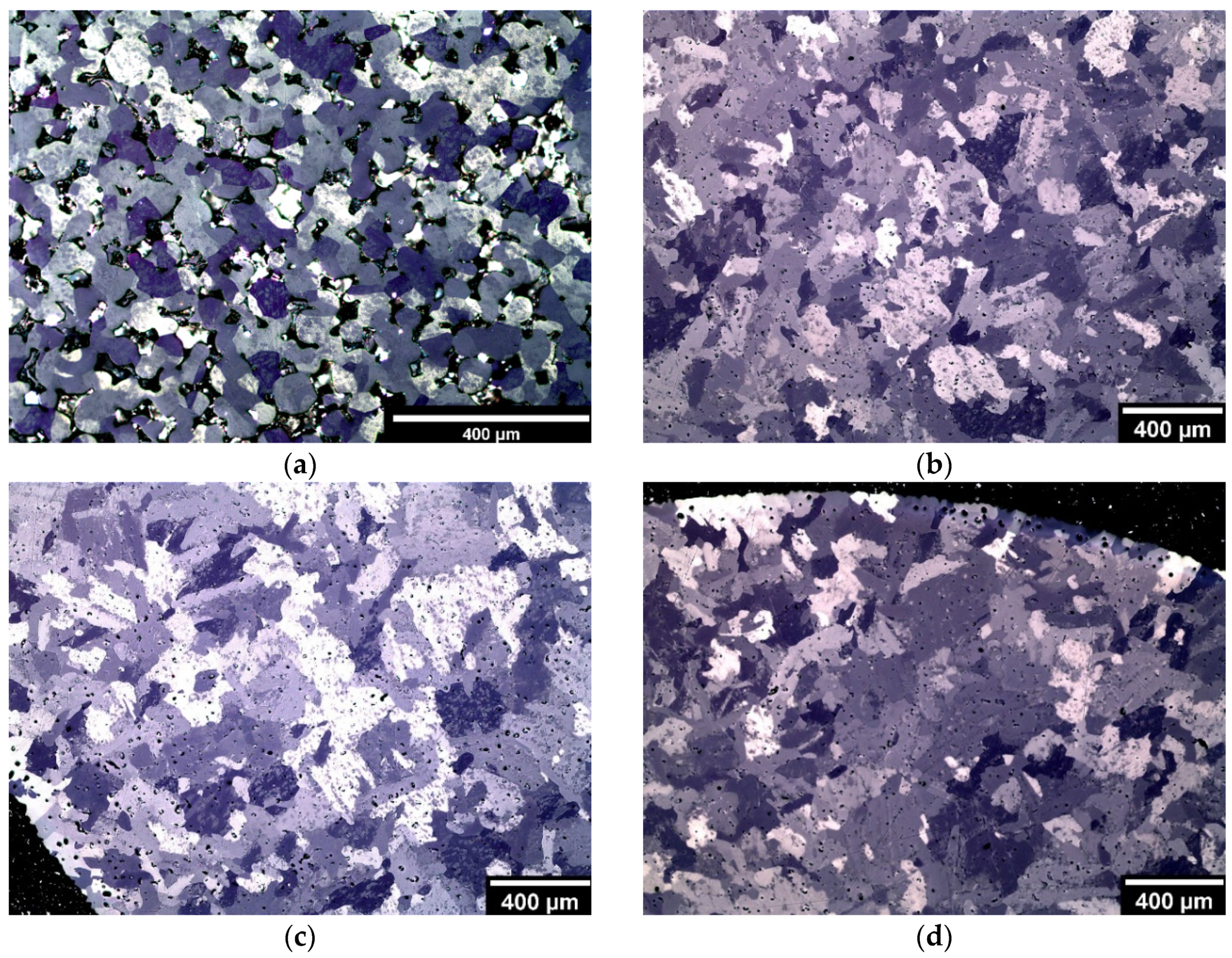
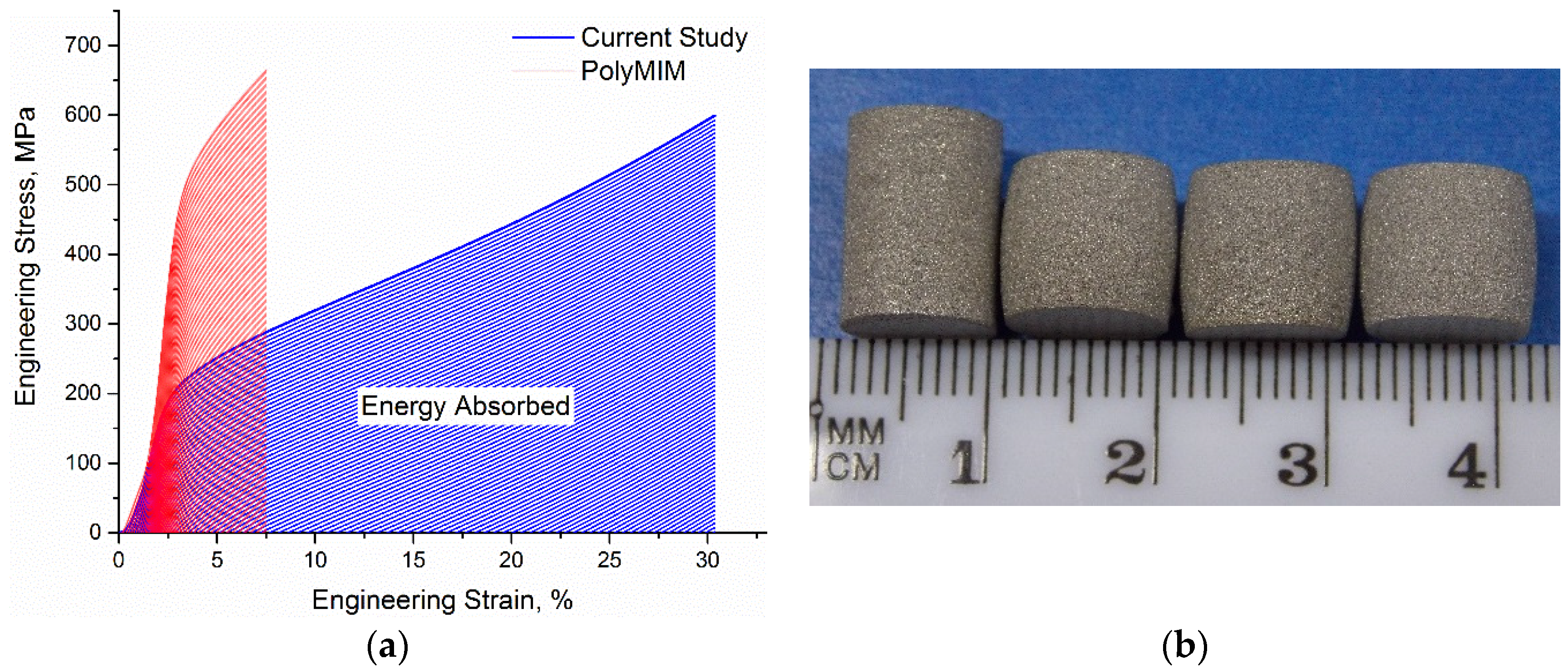
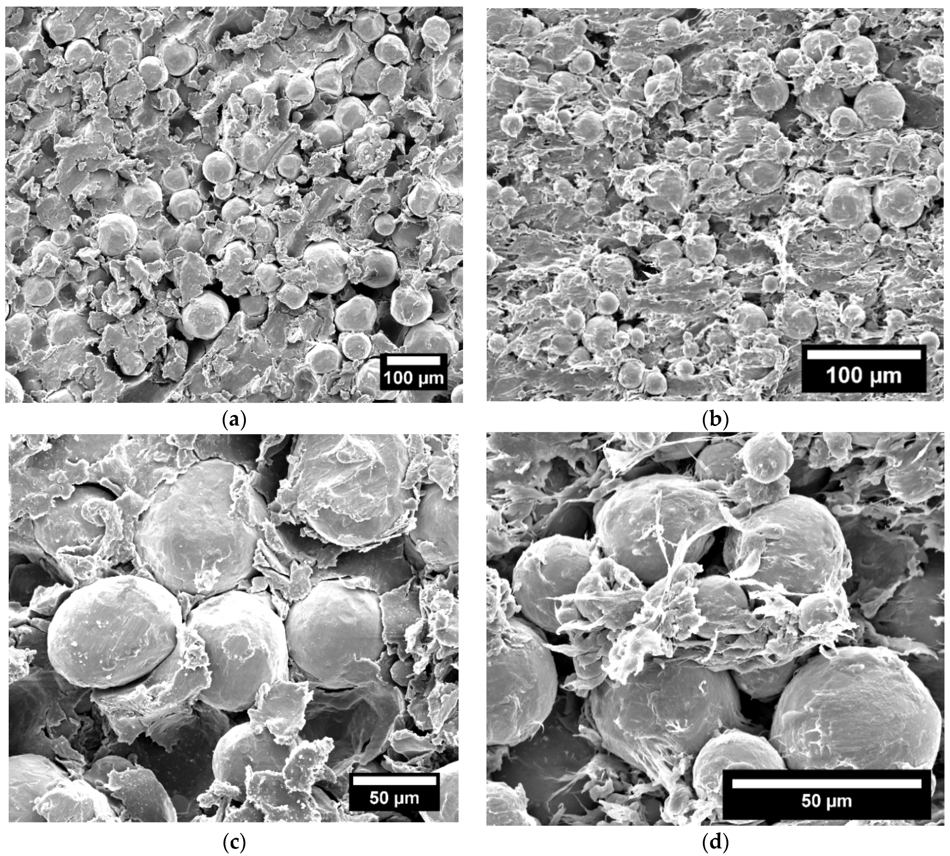
3.4. Microstructural and Mechanical Analysis Results

Optical microscopy images of the polished cross-sections of the prepared samples of both feedstocks are shown in Figure 10.
It was found that samples made by the coarse Ti powder had much larger micropores with less sphericity. These micropores are formed due to incomplete sintering and bonding amongst the adjacent Ti particles. In comparison, samples processed by commercial feedstock had much finer micropores and more spherical sizes that tend to increase towards the outer edges of the specimens. The average pore diameter for the commercial feedstock was about 17 μm with a sphericity of about 0.63, whereas the average pore diameter for the current feedstock was about 57 μm with a sphericity of about 0.49. Hence, it is expected that samples processed by commercial feedstock have better mechanical properties than those processed with the coarse Ti powder. Nevertheless, the relatively large micropores in the samples processed by the coarse Ti powder are well suited for biomedical applications, where pore sizes greater than 50 μm are required for rapid osteoconduction [25]. It should be noted that the optimum pore size range for bone ingrowth, cell attachment and proliferation is 100–500 μm [26]. However, pore sizes in the samples could be increased with the introduction of a space holder material in the feedstock mixture and removing it at a later stage during sintering [8,27].
The results of mechanical tests for the samples are presented in Figure 11.
The compression test results indicate that samples processed by the commercial feedstock have a significantly higher yield strength compared to those processed by the coarse Ti powder, where the average yield strengths ( σ 0.2 ) for the samples were about 473 and 191 MPa, respectively. However, the energy absorbed by the samples processed by the coarse Ti powder was notably higher than that absorbed by the samples made with the commercial feedstock, and this is one of the unique characteristics for porous materials, as the samples processed by the coarse powder had an average volume percentage of porosity around 20%. Yet, the stress-strain curve for these porous samples did not show any plateau stress, such as that classically expected during testing of porous materials. The samples after testing did not show nor develop any cracks and showed some signs of barrelling, which is typically observed during compression testing, as seen in Figure 11.

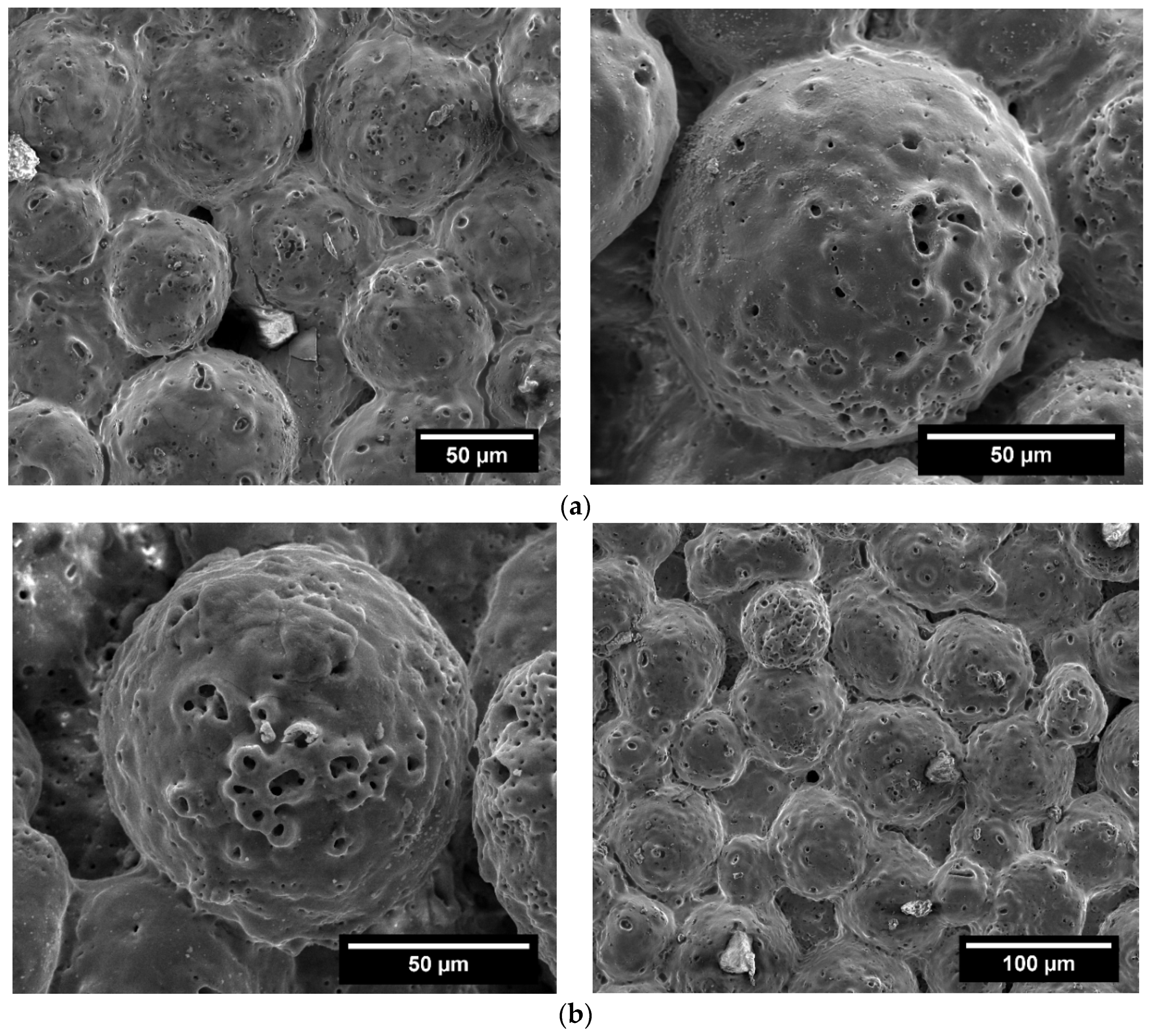
3.5. Characteristics of PEO-Coated Samples

The surface morphology of the porous samples coated using the PEO process is shown in Figure 12.
It can be seen that Ti particles are covered with a rough PEO coating, showing some traces of electrical discharges in the form of craters on the surface. These micro-craters are formed locally due to the dielectric breakdown of the growing oxide layer accompanied with gas evolution during the coating process, leaving interconnected microporous channels, with openings resembling the mouth of volcanic crater. The lifetime of these micro discharges during PEO treatments of Ti often ranges from 100–800 ms with sizes being in the range of 80–380 μm [28]. The average pore diameter for these craters was found to be about 4.2 ± 0.4 and 5.5 ± 0.5 μm for coatings formed during 4 and 8 min, respectively. It can also be noted that some micropores, which resulted from the partial sintering and necking of the Ti particles during the production process, were covered with the oxide layer, as shown in Figure 12. Four partially sintered Ti particles around a pore (at the ground surface for clarity) before PEO treatment and another group (not ground) after treatment are shown in Figure 13.
It can be argued that the micropores among the Ti particles before the PEO treatment were larger with more irregular shapes, whereas after the PEO treatment, pore sizes were significantly smaller and more round.
The result of the phase compositional analysis for the sample treated for 4 min is illustrated in Figure 14.
It was found that the surface was mainly composed of anatase with some rutile titanium dioxide regardless of the treatment time. The phase compositional results for these PEO-coated porous Ti samples are quite comparable to those reported for dense commercially-pure Ti PEO coated using trisodium orthophosphate electrolyte with a concentration in the range 5–15 g·L−1 [29].

4. Discussion

The principal aim of this study was to evaluate the use of a relatively coarse Ti powder in the production of MIM parts with the potential for biomedical applications and their subsequent surface modification via PEO. This can be seen by the comparison between the feedstock of a coarse Ti powder (mean particle size of 75 μm) with a three-component polymeric binder system (PEG, PMMA and SA), with a commercial feedstock (PolyMIM Grade 2).
DSC curves (Figure 3) showed that the current study feedstock requires a lower temperature to be successfully injection moulded than commercial feedstock, where the peak melting temperature of the high viscosity part of the current study binder (PMMA) was 14% lower than that for commercial feedstock. It should be noted that the SA peak could not be detected in the DSC diagram for the current study binder, which could be ascribed to the small amount of SA in the mixture, as has been observed in the literature [30]. In addition, the results of the DSC analysis suggested that the commercial binder consists of more than two parts and does not only contain polypropylene as previously reported, but also high density polyethylene. This was supported by the results of the FTIR analysis, Figure 4. Based on the DSC results, the current study feedstock was injection moulded at a temperature 10% higher than the peak melting temperature of the high viscosity part of the binder, to ensure complete melting. In contrast, the commercial feedstock was injection moulded at a temperature of 185 °C (chosen based on the specification of 178–186 °C), which is about 17% higher than the melting point of the high viscosity part of its binder.
Viscosity analysis results (Figure 5) demonstrated that both feedstocks exhibit some shear thinning behaviour, which is desirable in MIM. This can arise where shear rate decreases viscosity due to the unfolding, stretching and alignment of the tangled polymer chains and the breakage of the particle agglomerates [13,31]. The sensitivity with which the shear viscosity changes with shear rate is usually assessed by the flow behaviour index (n). The lower the n value, the higher the shear sensitivity and the more the feedstock shows pseudoplasticity or shear thinning [32]. Thus, Table 2 shows that the commercial feedstock exhibits the most pseudoplasticity. However, a low value of n may also be associated with some moulding defects, including jetting, and leads to the slip flow phenomenon [33]. It was also found that the commercial feedstock has a much higher shear viscosity and yield stress, despite being tested at much higher temperatures. The high shear viscosity, yield stress and shear sensitivity could be attributed to several factors, including the high viscosity of the polymers used in the commercial binder and the high solid content for such commercial feedstocks [33] (usually in the range of 60%–65%), as well as the small Ti particle size used [34].
Sintered samples of the commercial feedstock injection moulded using the vertical plunger-type injection moulder showed relatively large macro-cracks, as shown in Figure 7b. These cracks were up to 2 mm in length and might be formed due to the insufficient injection and backing pressure of the vertical plunger-type injection moulder. Sintered samples processed by the same feedstock using the Arburg 320 all-rounder with a pressure more than three-times higher and a temperature of 195 °C exhibited smaller cracks, Figure 8. In comparison, sintered samples of the current study feedstock processed using the vertical injection moulder did not show any cracks.
The average relative density of the samples sintered using the current study feedstock was found to be 14% lower than that of the samples processed using commercial feedstock with a volume percentage of porosity of about 20%, while the average volume shrinkage for the samples after sintering was 35% lower than that for samples processed by the commercial feedstock. The differences in shrinkage and density between the samples produced by commercial and current study feedstock could be attributed to the relatively large Ti particle size used in the current study feedstock compared to that of the commercial feedstock, as the use of a smaller particle size results in sintering (and therefore, shrinkage) proceeding more rapidly [35], due to the greater amount of surface energy present [36]. This may also explain the fact that pores in the samples made using the commercial feedstock were much more spherical and more regular in shape (Figure 10).
The average linear shrinkage of the parts processed by the commercial feedstock (12.51%) lies in the typical range of linear shrinkage for MIM parts in the literature (14%–18%) [37], whereas for samples produced by the current study feedstock, it was significantly lower (7.3%). Hence, the use of a coarse particle size can be advantageous in increasing the competitiveness of MIM among other manufacturing processes in terms of cost, as well as dimensional tolerances and shrinkage.
In terms of pore size, the average pore diameter for samples processed by the current study feedstock was found to be three-times higher than that of the commercial feedstock, and the pores were less regular.
It should be noted that samples made here using the commercial feedstock had a slightly lower density (higher porosity) and larger pore size compared to that reported for sintered MIM parts using other commercial feedstocks, e.g., for Catamold® Ti BASF (Ludwigshafen, Germany), porosity is about 4% with a pore size of less than 10 μm [38]. These differences might be attributed to the sintering time and temperature (samples were sintered in the previous study at 1300 °C for more than three hours), as well as the Ti particle size (reported to be 2–35 μm in the BASF feedstock [38]), finer than that estimated here for PolyMIM feedstock (12–45 μm). It should however be noted that, as the solid content for both commercial feedstocks is not known, an exact comparison is not possible.
Chemical analysis of the interstitial elements (Table 3) showed that samples made by the commercial feedstock had a carbon content approximately half of that detected in samples made by the current study feedstock, even though the finer Ti powder would be more prone to contamination. This could be attributed to the use of PMMA in the current study binder, which decomposes during thermal debinding, releasing large amounts of carbonaceous gases, which may subsequently react with Ti. Nevertheless, the amount of carbon in samples made using the current study feedstock is lower than that reported for BASF feedstock (0.09%–0.11% [38]).
The results of the mechanical tests (Figure 11) showed that samples made by the current study feedstock had a yield stress ( σ 0.2 ), 60% lower than that for samples made using commercial feedstock, but a much higher ability to absorb strain. The higher porosity and larger micropores of the samples made by the current study feedstock will lead to reduced strength, though the porosity also increases the energy absorption capacity in plastic deformation [39].
PEO treatment of the microporous MIM parts produced by the current study resulted in the formation of a rough oxide coating with micro-craters, as can be seen from Figure 12. During PEO treatment, Ti initially reacts with the oxygen that results from the electrolysis of the aqueous electrolyte solution to form amorphous Ti oxide. Under the immense heat and pressure generated by the electrical discharges, the oxide is crystallized to form a metastable anatase, which may be transformed to thermodynamically-stable rutile [29]. The amorphous and metastable anatase oxides are normally formed in the temperature range of 250–400 °C, whereas the rutile transformation occurs in the temperature range of 400–800 °C [40]. XRD analysis of the phase composition of the surface showed that the main oxide present in the sample is anatase with a minor amount of rutile oxide. Similar findings were reported in the literature for dense Ti [41,42]. The dominancy of the formation of anatase oxide in the samples could be attributed to the high electrolyte concentration used in the PEO treatment (14 g·L−1), where the abundance of phosphorus in the electrolyte is reported to delay crystallization and transformation from anatase to rutile oxide [29].
Compared to the state before PEO treatment, the surface of the samples after PEO treatment had a much rougher appearance and was covered with microporous channels with pore diameters that increased slightly with increasing treatment time, while the micropores that resulted from the partial sintering of the Ti particles become smaller and more regular in shape. Having a rougher surface can be an advantage for biomedical applications, where surface roughness can affect the amount and rate of bone tissue formation and, consequently, the rate of osseointegration [43]. The surface of the PEO-treated MIM samples is covered with biologically-active anatase/rutile coating that could induce apatite formation [44]. Thus, the PEO-treated microporous MIM parts would have an advantage over as-sintered MIM samples for biomedical applications.

5. Conclusions

The use of relatively coarse Ti powder in MIM technology with the potential for biomedical applications has been explored and compared with commercial Ti feedstock PolyMIM Grade 2 in terms of the rheological, melting and sintering behaviours, as well as dimensional shrinkages. Samples made by the current study feedstock with the coarse Ti powder shrank 35% less than samples processed by the commercial feedstock and had a relative density 14% lower than that of the samples processed using commercial feedstock. The average pore diameter for samples processed by the current study feedstock was approximately three-times larger than that of the commercial feedstock, and the pores were less round with a sphericity of about 0.49. Based on the results, it can be concluded that the use of coarse Ti powder could be beneficial in increasing the competitiveness of MIM among other processes for the production of biomedical parts, as it saves cost, reduces shrinkage and also results in more of the intentionally-induced micropores that are desired for cell attachment and bone ingrowth. In addition, plasma oxidation treatment for the microporous samples processed by the coarse Ti powder was carried out successfully, yielding a thick rough coating with interconnected microporous channels and openings resembling the mouth of a volcanic crater. The coating was mainly comprised of a mixture of rutile and anatase titanium dioxide. These coated microporous samples could have huge potential in biomedical applications, as they do not only possess different sizes of micropores that arise from the production process and PEO treatment, but also have a rough biologically-active surface, unlike pure Ti.

Acknowledgments

Partial support for this work was provided by the ERC Advanced Grant (#320879 ‘IMPUNEP’) and the Russian Ministry of Education and Science under Increase Competitiveness Program of National University of Science and Technology “MISiS” (No. K2-2016-011). One of the authors (MMS) would like to acknowledge a studentship from the Iraqi Ministry of Higher Education and Scientific Research.

Author Contributions

Mohammed Menhal Shbeh designed and performed the experiments, and analyzed the data. The study was conceived and the paper written by Mohammed Menhal Shbeh in collaboration with Aleksey Yerokhin and Russell Goodall, acting as supervisors.

Conflicts of Interest

The authors declare no conflict of interest.

References

  1. Heaney, D.F. Handbook of Metal Injection Molding; Elsevier: Amsterdam, The Netherlands, 2012. [Google Scholar]
  2. German, R.M. Progress in titanium metal powder injection molding. Materials 2013, 6, 3641–3662. [Google Scholar] [CrossRef]
  3. Wen, G.; Cao, P.; Gabbitas, B.; Zhang, D.; Edmonds, N. Development and design of binder systems for titanium metal injection molding: An overview. Metall. Mater. Trans. A 2013, 44, 1530–1547. [Google Scholar] [CrossRef] [Green Version]
  4. Qian, M.; Froes, F.H. Titanium Powder Metallurgy: Science, Technology and Applications; Butterworth-Heinemann: ‎London, UK, 2015. [Google Scholar]
  5. Komeya, K.; Inoue, H. Sintering of aluminium nitride: Particle size dependence of sintering kinetics. J. Mater. Sci. 1969, 4, 1045–1050. [Google Scholar] [CrossRef]
  6. De Vasconcellos, L.M.R.; Oliveira, F.N.; de Oliveira Leite, D.; de Vasconcellos, L.G.O.; do Prado, R.F.; Ramos, C.J.; de Alencastro Graça, M.L.; Cairo, C.A.A.; Carvalho, Y.R. Novel production method of porous surface Ti samples for biomedical application. J. Mater. Sci. Mater. Med. 2012, 23, 357–364. [Google Scholar] [CrossRef] [PubMed]
  7. Thelen, S.; Barthelat, F.; Brinson, L.C. Mechanics considerations for microporous titanium as an orthopedic implant material. J. Biomed. Mater. Res. A 2004, 69, 601–610. [Google Scholar] [CrossRef] [PubMed]
  8. Shbeh, M.M.; Goodall, R. Open pore titanium foams via metal injection molding of metal powder with a space holder. Met. Powder Rep. 2016, 71, 450–455. [Google Scholar] [CrossRef]
  9. Yan, W.; Berthe, J.; Wen, C. Numerical investigation of the effect of porous titanium femoral prosthesis on bone remodeling. Mater. Des. 2011, 32, 1776–1782. [Google Scholar] [CrossRef]
  10. Maetzig, M.; Walcher, H. Moulding equipment for the processing of coarse powders by metal injection moulding. Powder Inject. Mould. Int. 2013, 7, 1, 69–72. [Google Scholar]
  11. Rebl, H.; Finke, B.; Schmidt, J.; Mohamad, H.S.; Ihrke, R.; Helm, C.A.; Nebe, J.B. Accelerated cell-surface interlocking on plasma polymer-modified porous ceramics. Mater. Sci. Eng. C 2016, 69, 1116–1124. [Google Scholar] [CrossRef] [PubMed]
  12. Lampman, S. Characterization and Failure Analysis of Plastics; ASM International: Materials Park, OH, USA, 2003. [Google Scholar]
  13. Shbeh, M.M.; Goodall, R. Design of water debinding and dissolution stages of metal injection moulded porous Ti foam production. Mater. Des. 2015, 87, 295–302. [Google Scholar] [CrossRef]
  14. German, R.M.; Bose, A. Injection Molding of Metals and Ceramics; Metal Powder Industries Federation: Princeton, NJ, USA, 1997. [Google Scholar]
  15. Chhabra, R.P.; Richardson, J.F. Non-Newtonian Flow and Applied Rheology: Engineering Applications; Butterworth-Heinemann: London, UK, 2011. [Google Scholar]
  16. Syvitski, J.P. Principles, Methods and Application of Particle Size Analysis; Cambridge University Press: Cambridge, UK, 2007. [Google Scholar]
  17. Roberjot, S.; Auzene, D.; Iordache, L.; Baraldi, U. Water solvent debinding for PIM parts. PIM Int. 2011, 5, 51–54. [Google Scholar]
  18. Peacock, A.J. The chemistry of polyethylene. J. Macromol. Sci. C Polym. Rev. 2001, 41, 285–323. [Google Scholar] [CrossRef]
  19. Maier, C.; Calafut, T. Polypropylene: The Definitive User’s Guide and Databook; William Andrew: Norwich, NY, USA, 1998. [Google Scholar]
  20. Kumar, S.; Singh, R. Recovery of hydrocarbon liquid from waste high density polyethylene by thermal pyrolysis. Braz. J. Chem. Eng. 2011, 28, 659–667. [Google Scholar]
  21. Stuart, B. Infrared Spectroscopy; Wiley Online Library: Hoboken, NJ, USA, 2005. [Google Scholar]
  22. Klar, E.; Samal, P.K. Powder Metallurgy Stainless Steels: Processing, Microstructures, and Properties; ASM International: Materials Park, OH, USA, 2007. [Google Scholar]
  23. Zeng, W.; Li, S.; Chow, W. Preliminary studies on burning behavior of polymethylmethacrylate (PMMA). J. Fire Sci. 2002, 20, 297–317. [Google Scholar] [CrossRef]
  24. Petunina, Y.V. Effect of high oxygen and nitrogen contents on the mechanical properties of titanium. Met. Sci. Heat Treat. 1961, 3, 276–279. [Google Scholar] [CrossRef]
  25. Saito, T.; Takemoto, M.; Fujibayashi, S.; Neo, M.; Murakami, T.; Miyaji, F.; Nakamura, T. Quantitative comparison of osteoconduction between porousapatite and wollastonite-containing glass-ceramics with 5 different pore sizes. Bioceram. Dev. Appl. 2011, 1, 1–3. [Google Scholar] [CrossRef]
  26. Gibson, L.J.; Ashby, M.F.; Harley, B.A. Cellular Materials in Nature and Medicine; Cambridge University Press: Cambridge, UK, 2010. [Google Scholar]
  27. Shbeh, M.M.; Goodall, R. Single- and multi-layered porous titanium via metal injection moulding. Adv. Mater. Lett. 2016. [Google Scholar] [CrossRef]
  28. Matykina, E.; Berkani, A.; Skeldon, P.; Thompson, G.E. Real-time imaging of coating growth during plasma electrolytic oxidation of titanium. Electrochim. Acta 2007, 53, 1987–1994. [Google Scholar] [CrossRef]
  29. Khan, R.; Yerokhin, A.; Li, X.; Dong, H.; Matthews, A. Influence of current density and electrolyte concentration on DC PEO titania coatings. Surf. Eng. 2014, 30, 102–108. [Google Scholar] [CrossRef]
  30. Barbosa, A.P.C.; Bram, M.; Stöver, D.; Buchkremer, H.P. Realization of a titanium spinal implant with a gradient in porosity by 2-component-metal injection moulding. Adv. Eng. Mater. 2013, 15, 510–521. [Google Scholar] [CrossRef]
  31. Loukili, A. Self-Compacting Concrete; John Wiley & Sons: Hoboken, NJ, USA, 2013. [Google Scholar]
  32. Li, Y.M.; Huang, B.Y.; Qu, X.H. Viscosity and melt rheology of metal injection moulding feedstocks. Powder Metall. 2013, 42, 86–90. [Google Scholar] [CrossRef]
  33. Krauss, V.A.; Pires, E.N.; Klein, A.N.; Fredel, M.C. Rheological properties of alumina injection feedstocks. Mater. Res. 2005, 8, 187–189. [Google Scholar] [CrossRef]
  34. Smith, Y. High speed mixing of MIM feedstock. Met. Powder Rep. 1991, 46, 34–37. [Google Scholar]
  35. Srikanth, V.; Upadhyaya, G. Effect of tungsten particle size on sintered properties of heavy alloys. Powder Technol. 1984, 39, 61–67. [Google Scholar] [CrossRef]
  36. Seetharaman, S. Fundamentals of Metallurgy; Elsevier: Amsterdam, The Netherlands, 2005. [Google Scholar]
  37. Tandon, R. Net-shaping of Co-Cr-Mo (F-75) via metal injection molding. In Cobalt-Base Alloys for Biomedical Applications; ASTM International: Materials Park, OH, USA, 1999. [Google Scholar]
  38. Demangel, C.; Auzène, D.; Vayssade, M.; Duval, J.-L.; Vigneron, P.; Nagel, M.-D.; Puippe, J.-C. Cytocompatibility of titanium metal injection molding with various anodic oxidation post-treatments. Mater. Sci. Eng. C 2012, 32, 1919–1925. [Google Scholar] [CrossRef]
  39. Zhang, J.; Gungor, M.; Lavernia, E. The effect of porosity on the microstructural damping response of 6061 aluminium alloy. J. Mater. Sci. 1993, 28, 1515–1524. [Google Scholar] [CrossRef]
  40. Thorwarth, G.; Mändl, S.; Rauschenbach, B. Rutile formation and oxygen diffusion in oxygen PIII-treated titanium. Surf. Coat. Technol. 2001, 136, 236–240. [Google Scholar] [CrossRef]
  41. Chu, P.-J.; Wu, S.-Y.; Chen, K.-C.; He, J.-L.; Yerokhin, A.; Matthews, A. Nano-structured TiO2 films by plasma electrolytic oxidation combined with chemical and thermal post-treatments of titanium, for dye-sensitised solar cell applications. Thin Solid Films 2010, 519, 1723–1728. [Google Scholar] [CrossRef]
  42. Aliasghari, S.; Skeldon, P.; Thompson, G. Plasma electrolytic oxidation of titanium in a phosphate/silicate electrolyte and tribological performance of the coatings. Appl. Surf. Sci. 2014, 316, 463–476. [Google Scholar] [CrossRef]
  43. Novaes, A.B., Jr.; Souza, S.L.; Barros, R.R.; Pereira, K.K.; Iezzi, G.; Piattelli, A. Influence of implant surfaces on osseointegration. Braz. Dent. J. 2010, 21, 471–481. [Google Scholar] [PubMed]
  44. Yang, B.; Uchida, M.; Kim, H.-M.; Zhang, X.; Kokubo, T. Preparation of bioactive titanium metal via anodic oxidation treatment. Biomaterials 2004, 25, 1003–1010. [Google Scholar] [CrossRef]
Figure 1. The morphology of the Ti powder used.
Applsci 07 00105 g001
Figure 2. Schematic of the Plasma Electrolytic Oxidation (PEO) setup.
Applsci 07 00105 g002
Figure 3. DSC thermograms for the (a) commercial feedstock and (b) current study feedstock.
Applsci 07 00105 g003
Figure 4. FTIR spectrum of the commercial feedstock.
Applsci 07 00105 g004
Figure 5. Results of the viscosity measurements for (a) the commercial feedstock and (b) the current study.
Applsci 07 00105 g005
Figure 6. SEM images of the surface of as-broken samples of feedstocks from: (a) the current study at low magnification; (b) commercial at low magnification; (c) the current study at high magnification; (d) commercial at high magnification.
Applsci 07 00105 g006
Figure 7. (a) Side and top views of the sintered samples made by coarse powder; (b) side and top views of the sintered samples made by commercial feedstock PolyMIM Grade 2.
Applsci 07 00105 g007
Figure 8. (a) Side and top view of sintered and green samples; (b) lateral view of a crack.
Applsci 07 00105 g008
Figure 9. Relative densities and volume shrinkages after sintering for: (A) samples processed using commercial feedstock PolyMIM with the fine powder by plunger injection moulding; (B) samples processed using commercial feedstock PolyMIM with the fine powder by Arburg 320; (C) samples processed using current study feedstock with the coarse powder by plunger injection moulding.
Applsci 07 00105 g009
Figure 10. Optical micrographs of the polished samples for: (a) sample sintered using the current study feedstock; (bd) centre and edges of a sample sintered using commercial feedstock.
Applsci 07 00105 g010
Figure 11. Results of the mechanical tests showing: (a) stress-strain curves of the sintered samples; (b) samples processed by the coarse powder after compression.
Applsci 07 00105 g011
Figure 12. Morphology of the coating developed by PEO treatment for: (a) 4 min; (b) 8 min.
Applsci 07 00105 g012
Figure 13. Images of the ground surface of a sample before PEO treatment showing four partially-sintered Ti particles and the surface of a specimen (without grinding) after being subjected to PEO.
Applsci 07 00105 g013
Figure 14. XRD analysis result for PEO-treated sample for 4 min.
Applsci 07 00105 g014
Table 1. FTIR assignments of the commercial feedstock.
Wavenumber (cm−1)Type of Vibration
2950/2915C–H Stretching
2883CH3 and CH2 Stretching
2849C–H Stretching
718CH2 Rocking (Methylene Rocking)
1466C–H Scissoring (Methylene Scissoring) [21]
Table 2. Flow behaviour index and yield stresses for commercial and current feedstocks.
FeedstockTemperature (°C)Yield Stress (kPa)n
Commercial1701350.49
1851180.45
1951070.42
Current Study120790.63
135420.56
150350.53
Table 3. Chemical analysis results.
ContaminantSintered Sample from Commercial Feedstock (wt %)Sintered Sample in the Current Study (wt %)Ti Powder (wt %)
C0.044 0.079 0.006
O0.273 0.2770.093
N0.033 0.0230.010

