1. Introduction
Many efforts have been made to model and control quad-rotor Unmanned Aerial Vehicles (UAVs). In recent years, a wide number of strategies have been developed to solve the stabilization problem for this type of system using different methodologies in terms of control techniques and modeling approaches, such as [
1,
2,
3,
4]. Several strategies based on Euler angles provide an intuitive and easy way to visualize the quad-rotor kinematic and dynamical properties, but some obstacles are found with this representation, for instance, certain orientations can not be defined due to mathematical singularities, also a problem known as “gimbal lock” exists, which consists on an infinite number of possible representations for a single rotation. A potential solution for this problem is the use of unit quaternions to represent the rigid body rotations.
In the last years, several researchers have explored unit quaternions as an alternative to avoid these kind of issues. For instance, a quaternion-based nonlinear
controller, for solving the attitude problem of a quad-rotor is proposed in [
5], the proposed control scheme performs very well with a very small overshoot and a very good reference tracking, however only numerical simulations are presented to prove the efficiency of the suggested scheme. In [
6], a quaternion-based feedback is developed for the attitude stabilization of a quad-rotor. The control design takes into account a priori input bound and is based on nested saturations. The authors forced the closed-loop trajectories to enter in a fixed neighborhood around the origin in a finite time and remain thereafter. A quaternion-based nonlinear robust output feedback tracking controller is developed in [
7] to address the attitude and altitude tracking problem of a quad-rotor, here, approximation components based on neural network are introduced to estimate the model uncertainties and robust feedback components are designed to compensate for external disturbances. Also, [
8] investigates the attitude control design using backstepping technique for a quad-rotor represented by unit quaternions, external disturbance torques were taken into consideration, the attitude and the angular velocity of the quad-rotor were governed to be uniformly ultimately bounded by the proposed controller. Meanwhile, experimental results and implementation of a quaternion based attitude robust controller for quad-rotors are presented in [
9]. Here, a state feedback controller which compensates nonlinearities and uncertainties is proposed, attenuating their effects in the closed-loop control system. A robust controller based on quaternion for the attitude control problem of quad-rotors with a nominal controller and a robust compensator is proposed in [
10]. A quaternion based control scheme for the attitude control problem of a quad-rotor has been presented and experimentally evaluated in [
11]. Recent works of quad-rotor’s control based on quaternions can be found in [
12,
13,
14,
15,
16].
Few works based on PBC (Passivity-Based Control) strategies applied to UAVs can be found in the literature. For example in [
17], the authors presented a nonlinear control technique based on passivity to solve the path tracking problem for the quad-rotor, but only one control loop was considered in their work. For this work Souza, et al. showed that the PBC formulation leads to a set of partial differential equations constraints due to the underactuation degree of the system. In [
18] the authors proposed a controller based on an extension of Interconnection and Damping Assignment-Passivity Based Control (IDA-PBC) framework, for shaping the whole physical characteristics of a quad-rotor and for obtaining a desired interactive behavior between the vehicle and the environment. In [
19] a passivity-based approach is designed for this vehicle. The authors reduced the problem to the longitudinal plane to avoid solving complicated PDEs (Partial Differential Equations). A passivity-based control for a quad-rotor transporting a cable-suspended payload is presented in [
20]. Here, the problem is also reduced to the longitudinal plane to avoid complex PDEs. Finally, a passivity based controller for a PVTOL (Planar Vertical Take-Off and Landing) is introduced in [
21].
On the one hand, observe in these works that it is not possible to use passivity-based strategies directly to control the vehicle’s full dynamics because certain passivity properties are not satisfied, i.e., when this methodology is used directly in the classical quad-rotors equations, then only the attitude can be stabilized. Nevertheless, controllers based on PBC can be used if the dynamics are modified, this requires the use of more complex algorithms and high computational cost implementations for just a partial stabilization. On the other hand, IDA-PBC strategy is designed for underactuated systems. However, it requires computing complex PDEs, many of which may have not solution. The design of an IDA-PBC for a quad-rotor has this problem. By avoiding the complex PDEs, we can only control the quad-rotor’s attitude.
Motivated by the aforementioned considerations, in this work we introduce a methodology to analyze the quad-rotor vehicle using a passivity-based control with unit quaternions. The PBC strategy is obtained from the mathematical model based on Euler-Lagrange formulation using a quaternion logarithmic mapping such that a fully actuated virtual system is proposed, then an attitude trajectory in the quaternion space is used to apply the mathematical restrictions inherent to the quad-rotor. The resulting control scheme does not compute excessive and complex PDEs and can be designed directly from the model and can control the full quad-rotor equations. The proposed approach has no issues with singularities and can be straightforwardly applied in real-time experiments.
The paper is organized as follows: A brief survey of the main concepts of unit quaternions and passivity is presented in
Section 2. The representation of the quad-rotor dynamics in terms of unit quaternions is described with the logarithmic mapping in
Section 3. The quaternion-passivity-based control is developed in
Section 4. Numerical simulations are presented in
Section 5. Real-time experimental results are shown in
Section 6. Conclusions and perspectives are finally given in
Section 7.
3. Quad-Rotor Quaternion Dynamic Model
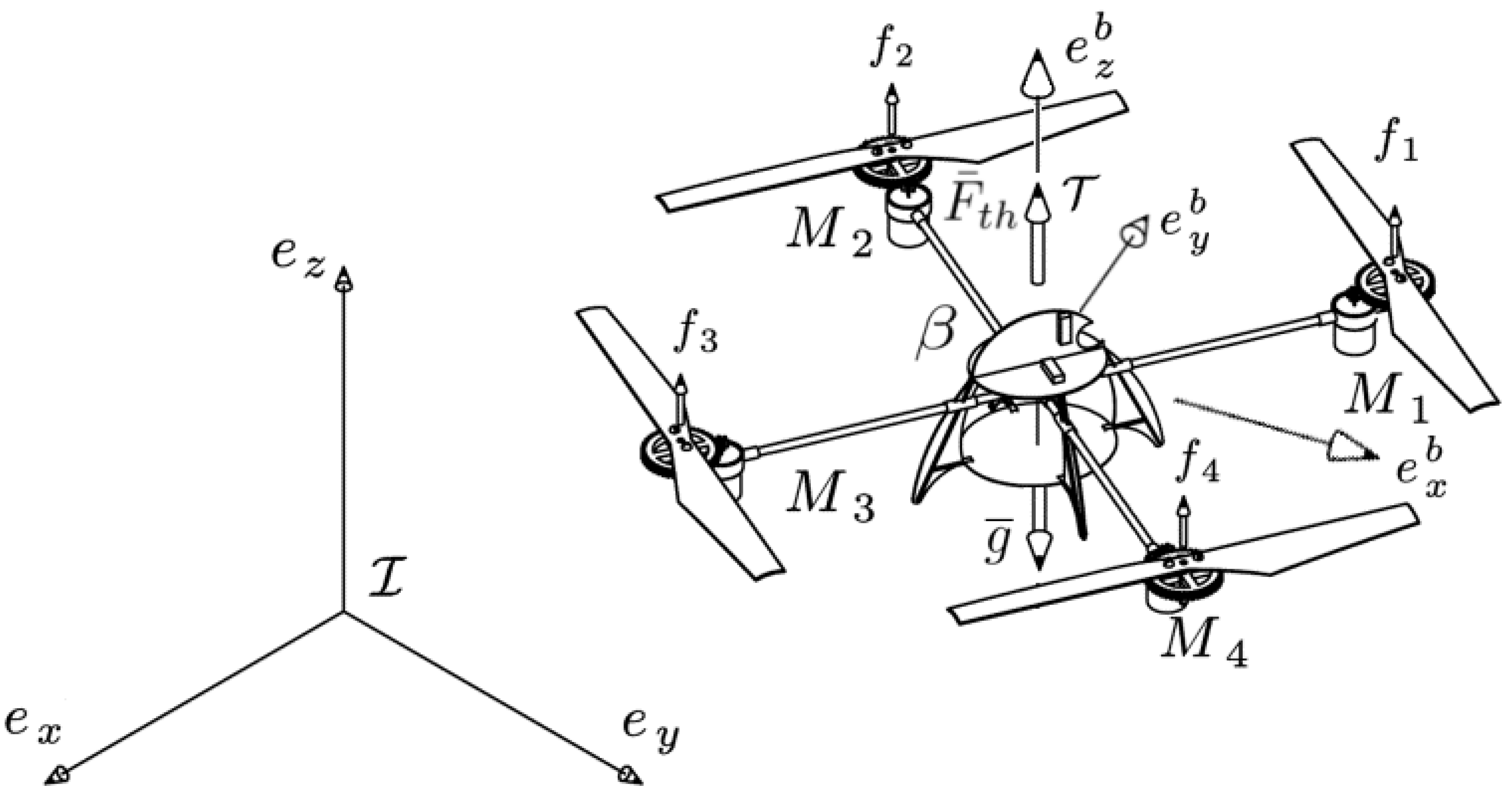
The body diagram of a quad-rotor can be drawn as in
Figure 2.
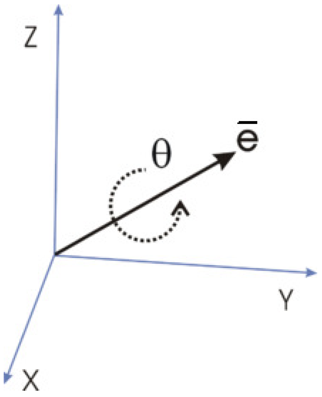
Let us consider an inertial coordinate frame fixed to the ground, a body fixed coordinate frame . Then, the vector ∈ defines all the states variables of the quad-rotor, where defines the position vector with respect to the inertial frame, denotes the rotation quaternion expressed in its axis-angle notation. defines the thrust vector generated by the four rotors, represents the gravity vector, contains the torques applied to the body’s center of mass, expressed on the aerial vehicle in the body-fixed frame.
3.1. Euler-Lagrange Methodology
The Lagrangian equation is known to be the difference between the kinetic and potential energies
We can obtain the motion equations applying the following expression
where
represents the input vector,
expresses the input force with respect to the inertial frame and
denotes the input torque to be computed by the control law.
3.1.1. Kinetic Energy
The total kinetic energy is obtained by the sum of the translational and rotational kinetic energies, which are obtained using the translational and rotational velocities respectively,
where
m denotes the vehicle’s mass, and
J represents the inertia matrix.
3.1.2. Potential Energy
The potential energy is described by the product of the mass, the gravity
g, and the height
z (the position in the vertical axis in the inertial frame)
3.1.3. Lagrangian Expression
Substituting (
11) and (
12) into (
9) the Lagrangian equation becomes
Solving (
13) with (
10) the dynamic equations are obtained as
Thus, the dynamic model can be expressed in matrix form as follows
where the inertia matrix is given by
which is symmetric and positive definite. The gravitational vector is given by
3.2. Coupled Dynamics Strategy
Notice that the quad-rotor is an under-actuated system, then the force
which is expressed in the inertial frame, is the force
rotated using a quaternion double product
Since the angular acceleration is given by the external torques and the internal rotational dynamics, then by Newton’s equations of motion, it follows that
thus the relation between the computed control input
from (
14) and the actual applied torque
from (
19) becomes
It is known that the translational and rotational dynamics of the quad-rotor are coupled such that the direction of the total force
depends only on the orientation of the UAV given by
, while its magnitude is equal to the total force given by the four rotors
, see
Figure 2 and Equation (
18). Then a rotation
must exist such that
is transformed into
in the inertial frame.
If the scalar product between these two vectors is defined as
where
denotes the axis on which the thrust acts in the body frame. The cross product is expressed by
Using some trigonometric identities to introduce (
21) and (
22) into the Euler-Rodrigues Formula from (
2), a quaternion attitude trajectory
can be introduced as
which is used to close the loop such that the orientation of coincides with thus the position is stabilized in the desired reference.
4. PBC Methodology for a Quad-Rotor Using Quaternions
The development of the mathematical model using quaternions simplifies the control law design. In the sense that the proposed control law is such that the quad-rotor system can be analyzed and controlled as a fully-actuated system. Also, the proposed control law avoids the issues with singularities.
The idea is to apply the PBC approach to (
15). Thus, the total energy is
In PBC methodology, the control input is naturally decomposed into two terms
where the first term is designed to achieve the energy-shaping and the second one injects the damping.
From (
4) notice that if we can find
such that
for some
and some constant
k, then the energy-shaping term
will ensure that the map
is passive with the following form for the desired energy function
where
represents the supplied energy by the controller. We will require that the function
has an isolated minimum at
, that is
The passive outputs for this system are the generalized velocities, that is
. The easiest way to shape the energy is by [
29]
where
stabilizes
with Lyapunov function the difference between the stored and supplied energies.
Then, introducing (
29) and
into (
26) we can obtain
where
contains design parameters. Substituting (
24) and (
30) into (
27), it follows that
The controller (
29) can be rewritten as
From (
32), we can ensure that the map
is passive with (
31) as the desired energy function.
The damping injection term is given by
where
contains design parameters.
To compute the final control law, consider that
and
. Now, we first determine the energy-shaping term
from (
32), which, in this case, takes the form
Note that the term is the quaternion error between the actual orientation and the desired reference . If the control law is such that , then , which implies that the orientation of the UAV converges to the desired reference . Here denotes the desired position.
Hence, we determine the damping injection term
from (
33)
where
, and the matrices
,
are composed by the tuning parameters. From (
25) the control law is applied to the model (
15) according to the following equivalence:
The obtained control law in quaternion space guarantees the stabilization of all the system states without any change in the model or in the PBC strategy. From (
8) can be observed that the PBC algorithm using Euler angles allows only to control the attitude.
Control Strategy Comparison
The comparison of various algorithms based on passivity applied to a quad-rotor are summarized on the
Table 1.
5. Numerical Validation
In order to validate the proposed mathematical scheme, the model and control law were simulated in a computer programming environment.
The control gains were selected beginning from identity matrices and adjusted empirically such that stable behavior of the system was well appreciated.
and
are adjusted to ensure the convergence to the desired references for the attitude and position respectively, while
and
act by reducing the setting time and the overshoot for the rotational and translational dynamics respectively. The values applied on the simulation are the following
with
,
,
, and
.
Our research team makes every effort to validate most of our algorithms in real experimental platforms. One of the drones we commonly use for tests is the Parrot AR Drone 2 which is cheap and easy to handle for attitude and position experiments, and was modified with a software framework that is compatible with other quad-rotors that our team has developed for more specific applications. For this reason, the mass and inertia matrix for the Parrot AR Drone 2 were needed, thus obtained from [
30], and used in our simulations.
Simulation Results
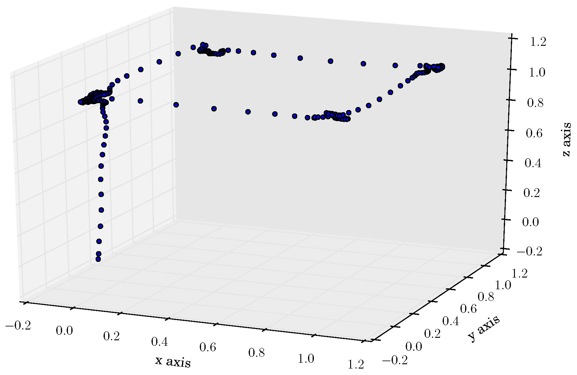
A simulated experiment was designed in which a position reference is given to the quad-rotor. A sequence of five set-points are defined in a time lapse of 25 seconds, thus following a 1 meter square at 1 meter height as illustrated in
Figure 3.
In order to proof in simulation the robustness to unknown bounded perturbations, additive uniformly distributed noise was considered with bounds empirically chosen between for the position, and between for the orientation, and translational and rotational velocities.
The feedback translational signals plus the additive noise close the loop to calculate the required force (see
Figure 4a) to move the vehicle in the 3D (3-dimensional) space. Note in this figure that the force in the
z axis is stabilized around
in order to maintain the vehicle’s altitude. The control torques are calculated such that the vehicle’s orientation
follows the trajectory
, see
Figure 4b.
The force in the inertial frame is then used to compute the orientation trajectory which will point the thrust force to the required direction in the inertial frame.
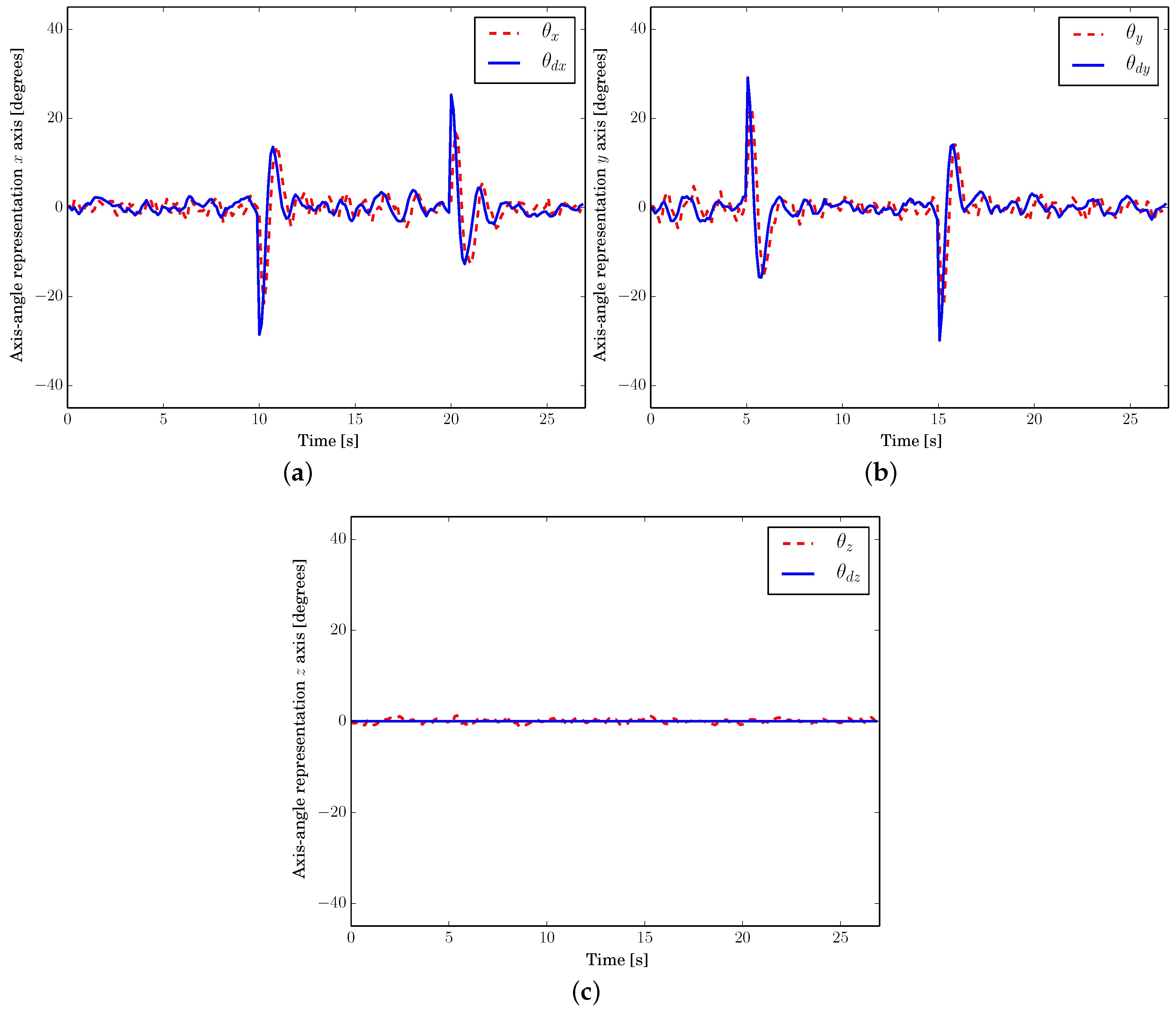
Figure 5 illustrates the trajectory tracking for the vehicle’s attitude, illustrated in axis-angle representation for a better understanding, here,
, and
.
Finally,
Figure 6 represents the translational stabilization. In the first one, the position for each axis is stabilized according to the reference.
The quality indicator IAE (Integral of Absolute Error) is chosen to compare the behavior and efficiency of the proposed controller with other control techniques for a quad-rotor using a quaternion representation of the attitude. PD (Proportional Derivative), LQR (Linear Quadratic Regulator) and backstepping control strategies presented in [
12] are selected to compare them with the PBC strategy. The results of IAE are shown in
Table 2.
We can observe that the quality indicators IAE for the four strategies are similar, i.e., they exhibit a very similar behavior. The two controller with better performance are PD and PBC for the positions x and y, Backstepping and PBC for the position z.
6. Flight Tests
Our proposed strategy was validated with real time indoor experiments using one of our laboratory’s Parrot AR Drone 2 vehicles (
Vedio S1). This UAV’s firmware was modified to work under a software framework which runs a Linux-based operating system, capable of implementing a wide range of conceived control schemes. An OptiTrack motion capture system was used to estimate the vehicle’s position and translational velocity, which was communicated to the drone using a Wi-Fi LAN, while its internal Inertial Measurement Unit (IMU) was used to measure its attitude quaternion and angular velocity, this configuration was chosen to maintain a minimal bandwidth usage in the wireless communications.
A Sony DualShock 3 controller was used to input a 3-dimensional position and velocity trajectory, which was controlled by one of our team members using joysticks. The generated trajectory was set as the desired position for the drone.
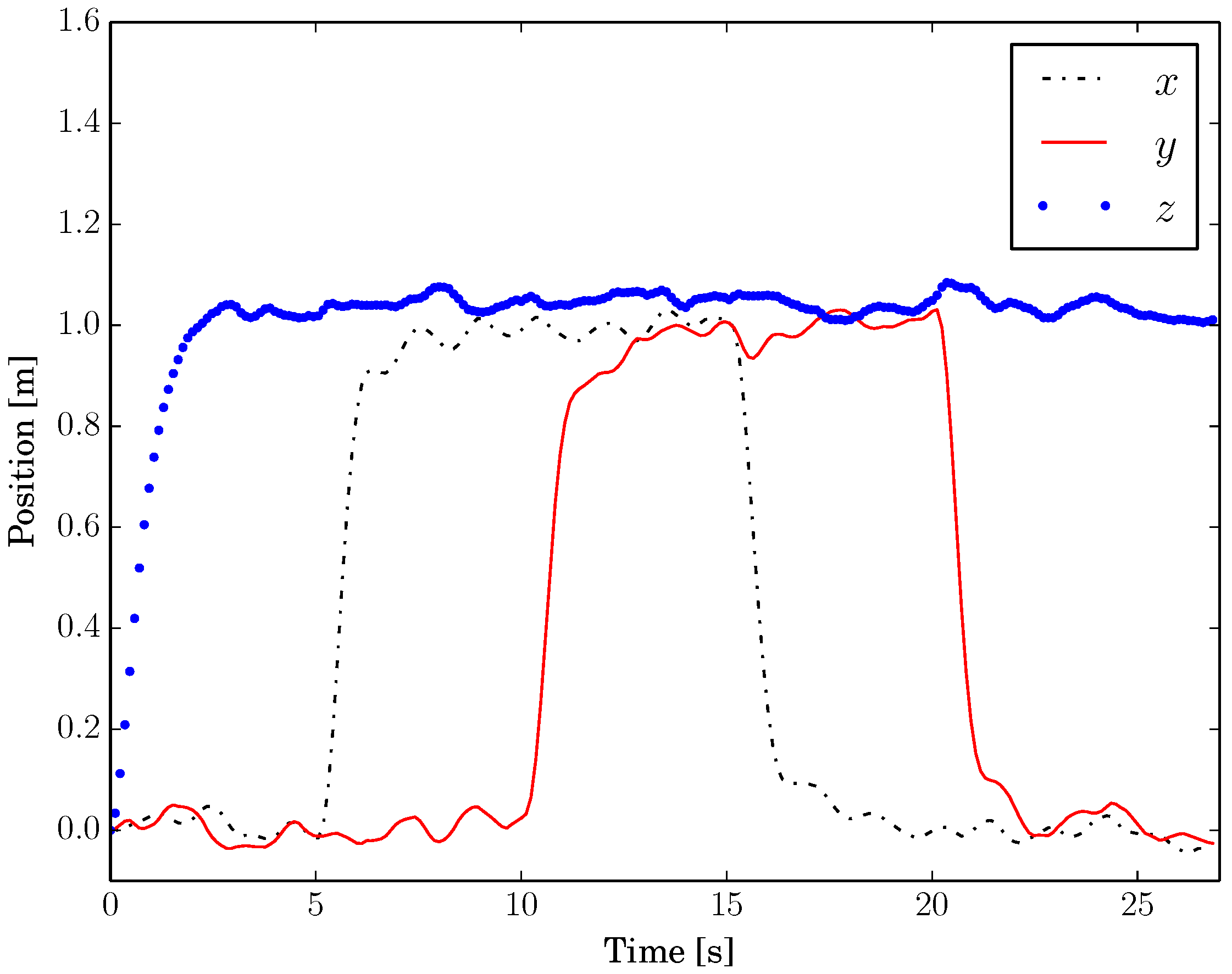
Figure 7 illustrates the UAV’s real trajectory and its reference in a real time experiment.
The trajectory given by the joystick is considerably fast, making strong movements to prove robustness. Notice the delay between the quad-rotor’s position and its reference when it is moving, and the convergence to the desired position when the reference is held static.
A desired control force is then computed using the position error, which is represented in
Figure 8. The
z component maintains a negative offset due to a compensation of the gravitational effects.
Since our framework is compatible with three different UAV configurations and models, the thrust force was set to be dimensionless. This means a force with norm 1 makes the motors output a maximum thrust, while norm 0 translates in no thrust force.
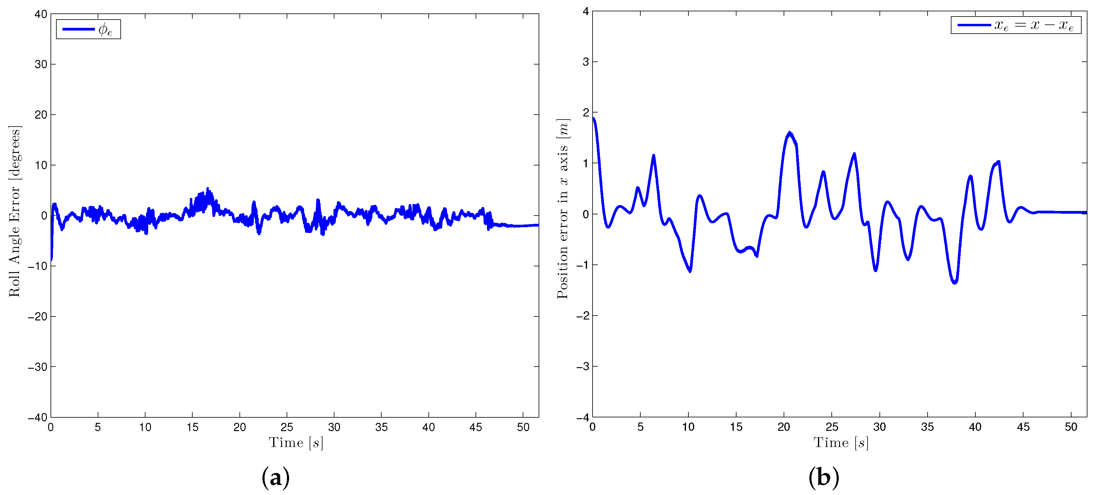
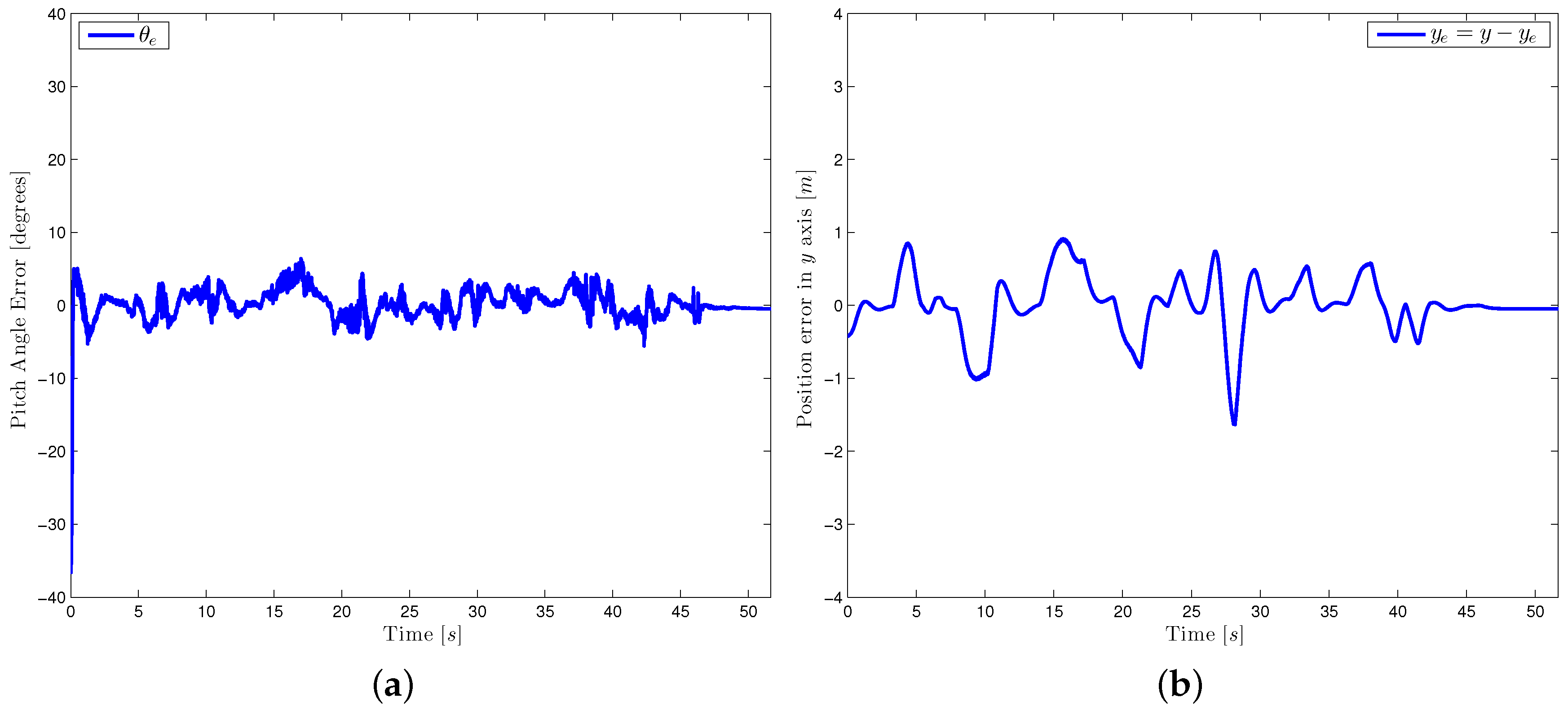
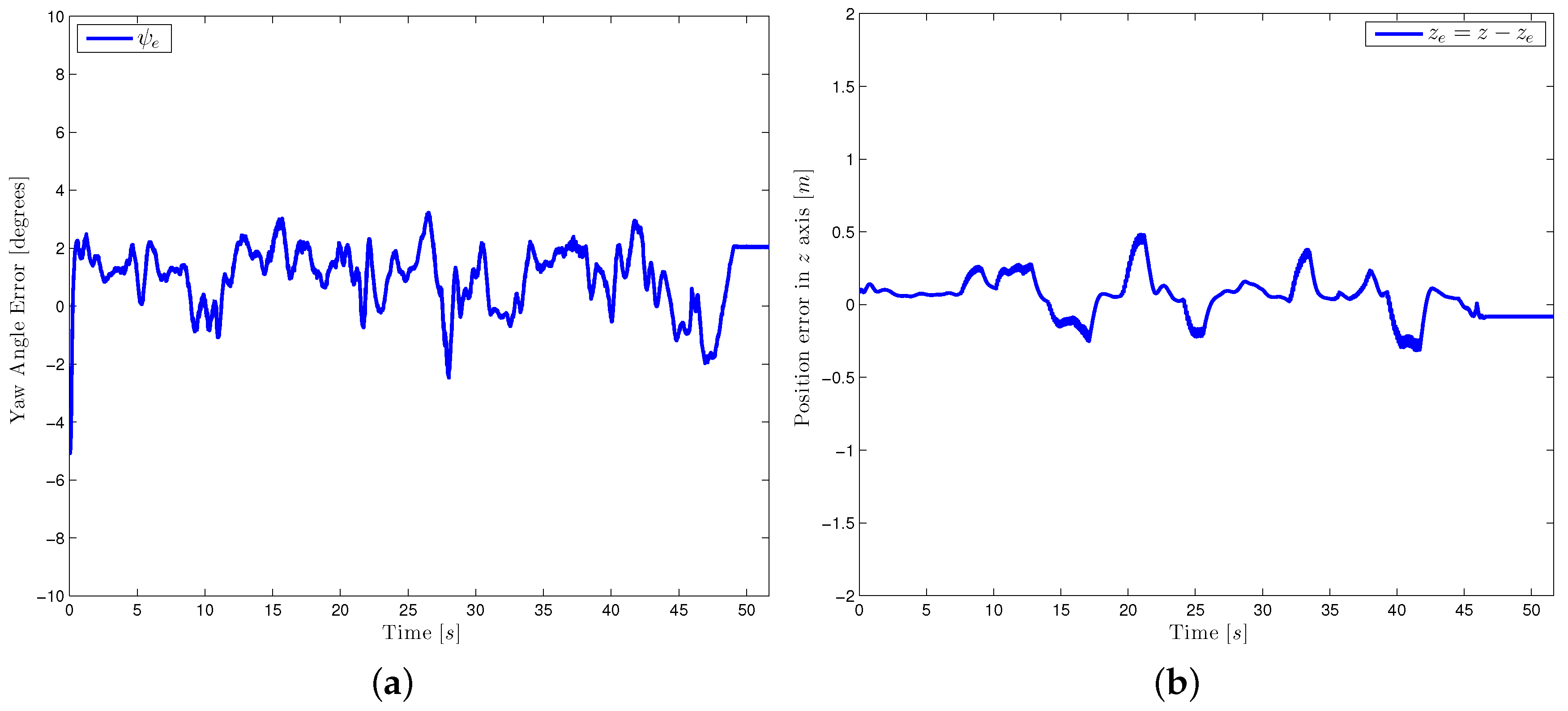
An attitude trajectory is now used to rotate the thrust force into the translational control law’s direction. The orientation controller then, assures the vehicle’s convergence to this reference. For a better visualization of the attitude dynamics, the equivalent Euler angles of the orientation error are illustrated in
Figure 9a,
Figure 10a,
Figure 11a, note the stabilization of around zero.
Finally,
Figure 9b,
Figure 10b,
Figure 11b represent the stabilization of the position error. Note the proposed control strategy well stabilizes the quad-rotor, even if the desired trajectories include strong displacements.
7. Conclusions
In this work, a mathematical model via the Euler-Lagrange formalism using the axis-angle attitude representation of a unit quaternion by its logarithmic mapping was presented. The mathematical model using quaternions was found to be a fully-actuated system and this simplifies the control law design.
A new methodology: quaternion-passivity-based control for a quad-rotor was presented. The proposed algorithm does not compute excessive and complex partial differential equations for obtaining the control law. The methodology can be designed directly from the model and can control the full quad-rotor dynamics.
The developed control scheme avoided the issues with singularities and was found to perform with good results for the control objective, as shown in the simulations and real-time results.
Future works include the use of this strategy for aerial manipulation tasks.
