Article

Experimental and Numerical Investigation on Non-Newtonian Nanofluids Flowing in Shell Side of Helical Baffled Heat Exchanger Combined with Elliptic Tubes

1
Key Laboratory of Enhanced Heat Transfer and Energy Conservation, The Ministry of Education, School of Chemistry and Chemical Engineering, South China University of Technology, Guangzhou 510640, China
2
Guangdong Engineering Technology Research Center for Petrochemical Energy Conservation, School of Chemical Engineering and Technology, Sun Yat-sen University, Guangzhou 510275, China
*
Author to whom correspondence should be addressed.
Appl. Sci. 2017, 7(1), 48; https://doi.org/10.3390/app7010048
Submission received: 25 October 2016 / Revised: 26 December 2016 / Accepted: 28 December 2016 / Published: 4 January 2017

Abstract

:
In this paper, an aqueous solution of xanthan gum (XG) at a weight fraction as high as 0.2% was elected as the non-Newtonian base liquid, the multi-walled carbon nanotubes (MWCNTs) dispersed into non-Newtonian XG aqueous at different weight factions of MWCNTs was prepared. Convection heat transfer of non-Newtonian nanofluids in the shell side of helical baffled heat exchanger combined with elliptic tubes has been investigated experimentally and numerically using single-phase flow model. Results showed that the enhancement of the convective heat transfer coefficient increases with an increase in the Reynolds number and the nanoparticle concentration. For nanofluids with 0.2 wt %, 0.5 wt % and 1.0 wt % MWCNTs, the Nusselt number, respectively, increases by 11%, 21% and 35% on average at the same Reynolds number, while the comprehensive thermal performance factors are 3%–5%, 15%–17% and 24%–26% higher than that of base fluid at the same volume rate. A remarkable heat transfer enhancement can be obtained by adding MWCNTs into XG aqueous solution based on thermal resistance analysis. Correlations have been suggested for the shell-side Nusselt number and friction factor of non-Newtonian nanofluids in the helical baffled heat exchanger with elliptic tubes. Good agreements existed between corrections and experimental data.

1. Introduction

Owing to the advanced enhancements on thermophysical property, transport property and heat transfer potentials in many industrial applications [1,2,3,4,5], nanofluids, first proposed by a research group in Argonne National Laboratory in the USA in 1995 [6], have attracted significant interest. A nanofluid is a uniform and stable suspension, composed of nanoparticles and base fluid. As the addition in nanofluid, the nanoparticles can be metal and/or nonmetal whose typical size is no larger than 100 nm. Many experimental and numerical investigations have been implemented on heat transfer enhancement of nanofluids in open literature. However, most of these works have used Newtonian fluids as the base fluid, while little attention has been paid on the nanofluids based on non-Newtonian fluids [7,8,9,10,11,12,13,14,15,16,17,18,19,20].
Non-Newtonian fluids, that is, against Newton’s law of viscosity, have been widely used in many industries such as food, petrochemical, pharmaceutical industries, etc. However, the viscosity of non-Newtonian fluids is usually greater, involving low Reynolds number and high Prandtl number. Consequently, in the process of flow and heat transfer, the pressure drop is high while the heat transfer coefficient is considerably low [21]. To overcome the aforementioned disadvantages existing in non-Newtonian fluids, nanoparticles are added and form non-Newtonian nanofluids, whose thermophysical properties are improved. Tian et al. [22] dispersed MWCNTs into an aqueous solution of carboxymethyl cellulose at a weight fraction of 3 wt % and obtained non-Newtonian nanofluids with 0.1 wt %, 0.5 wt %, 1 wt %, and 2 wt % MWCNTs. Results indicated that the thermal conductivity of all the nanofluids is higher than that of the base liquid and the thermal conductivity enhancement is as high as 14.6% for the nanofluid containing 2 wt % MWCNTs. Hojjat et al. [23] dispersed γ-Al2O3, TiO2 and CuO nanoparticles into an aqueous solution of carboxymethyl cellulose to form three types of non-Newtonian nanofluids and compared their heat transfer performances flowing through a uniformly heated circular tube. Results showed that both Nusselt number and convective heat transfer coefficient were enhanced by nanoparticles and increase with an increase in the nanoparticle concentration.
Up to now, researches and investigations mainly focus on the improvement of thermophysical properties or the flow and heat transfer characteristics in heat transfer equipment with extremely simple structure such as a single heated tube. As a necessary section in many industries, shell-and-tube heat exchangers are commonly used to heat or cool the process fluid. The flow and heat transfer performance of non-Newtonian fluids flowing in shell-and-tube heat exchangers is worth studying, but only a few investigations have been reported in open literature.
In addition to disperse nanoparticles, improving the structure of shell-and-tube heat exchangers is another effective means of enhancing heat transfer rate and reducing flow resistance. The baffles are an important section in shell-and-tube heat exchangers because they not only support the tube bundles but also direct the working fluid flow. Compared with segmental baffles, helical baffles showed better performance. Experimental result obtained by Kral et al. [24] indicated that the ratio of heat transfer coefficient to pressure drop in the shell side of heat exchanger with helical baffles is higher than that of heat exchanger with segmental baffles. Other than optimization of the baffles, utilizing enhanced tube is another way to improve heat transfer coefficient. Zhang et al. [25,26,27] have experimentally and numerically compared the shell side heat transfer performance of helical baffle heat exchanger with fin tubes and smooth tubes using oil and water as the working fluids. The results showed that the shell side heat transfer coefficient was obviously enhanced by finned tubes at the helical flow condition. Recently, He et al. [28] carry out a numerical investigation on performance comparison of non-Newtonian fluid flow in vertical heat exchangers combined helical baffle with elliptic and circular tubes. Results showed that the shell-side Nusselt number of the elliptic tubes heat exchanger are 11.4%–16.6% higher than those of the circular tubes heat exchanger, while the shell-side friction factor is 29.2%–36.9% lower. However, compared with heat transfer coefficient of water flowing in the elliptic tube side at fully turbulent flow condition, heat transfer coefficient of non-Newtonian fluid flowing in the shell side is lower.
To further improve the shell-side heat transfer coefficient of the helical baffled heat exchanger with elliptic tubes, non-Newtonian nanofluids were prepared. An aqueous solution of xanthan gum (XG) with 0.2 wt % concentration and multi-walled carbon nanotubes (MWCNTs) were selected as non-Newtonian base fluid and additives, respectively. The weight fractions of nanoparticle were set at 0.2 wt %, 0.5 wt % and 1.0 wt %. In the current study, the flow and heat transfer characteristics of non-Newtonian nanofluids flowing in the shell side of the helical baffle heat exchanger with elliptical tubes was experimentally and numerically investigated. The simulation of shell-side performance was conducted using commercial software FLUENT. Necessary thermo-physical properties and rheological characteristics of XG aqueous solution and its nanofluids were measured for calculation and simulation. The overall and shell-side heat transfer coefficient, ratio of shell-side thermal resistance to overall thermal resistance, Nusselt number, friction factor, Euler number and comprehensive thermal performance of base fluid were compared with non-Newtonian nanofluids.

2. Experimental Method

2.1. Sample Preparation and Measurements

Aqueous solutions of XG with 0.2% weight fraction of XG was prepared by dissolving XG into deionized water using ultrasonic vibration for about 1 h to obtain a uniform dispersion. Aqueous solutions of XG were added into the suspension of MWCNTs and, after thoroughly mixing, a MWCNTs-dispersed non-Newtonian nanofluid was obtained. To investigate the effect of the weight fraction of MWCNTs on the flow and heat transfer characteristics of the nanofluids, non-Newtonian nanofluids with 0.2 wt %, 0.5 wt %, and 1 wt % MWCNTs were prepared.
Rheological characteristics of the base fluid and the non-Newtonian nanofluids were measured using a rotational rheometer (TA-Instrument. Inc., ARG2, New Castle, DE, USA) with an accuracy of ±5%. The thermal conductivity and specific heat were measured using thermal constant analyzer (TPS2500, Hot Disk Co., Ltd., Uppsala, Sweden) and DSC (Q20, TA Instruments Co., Ltd., New Castle, DE, USA), respectively. The reported accuracies of TPS2500 and Q20 are ±3% and ±5%, respectively. The densities of samples are obtained by a densitometer with an accuracy of ±0.0001 g·cm−3. All the measurements were carried out in the range of temperature varying from 25 to 65 °C by using a constant temperature bath which was able to maintain temperature uniformity within ±0.1 °C. At least three measurements were taken at each temperature, and an average value was calculated.

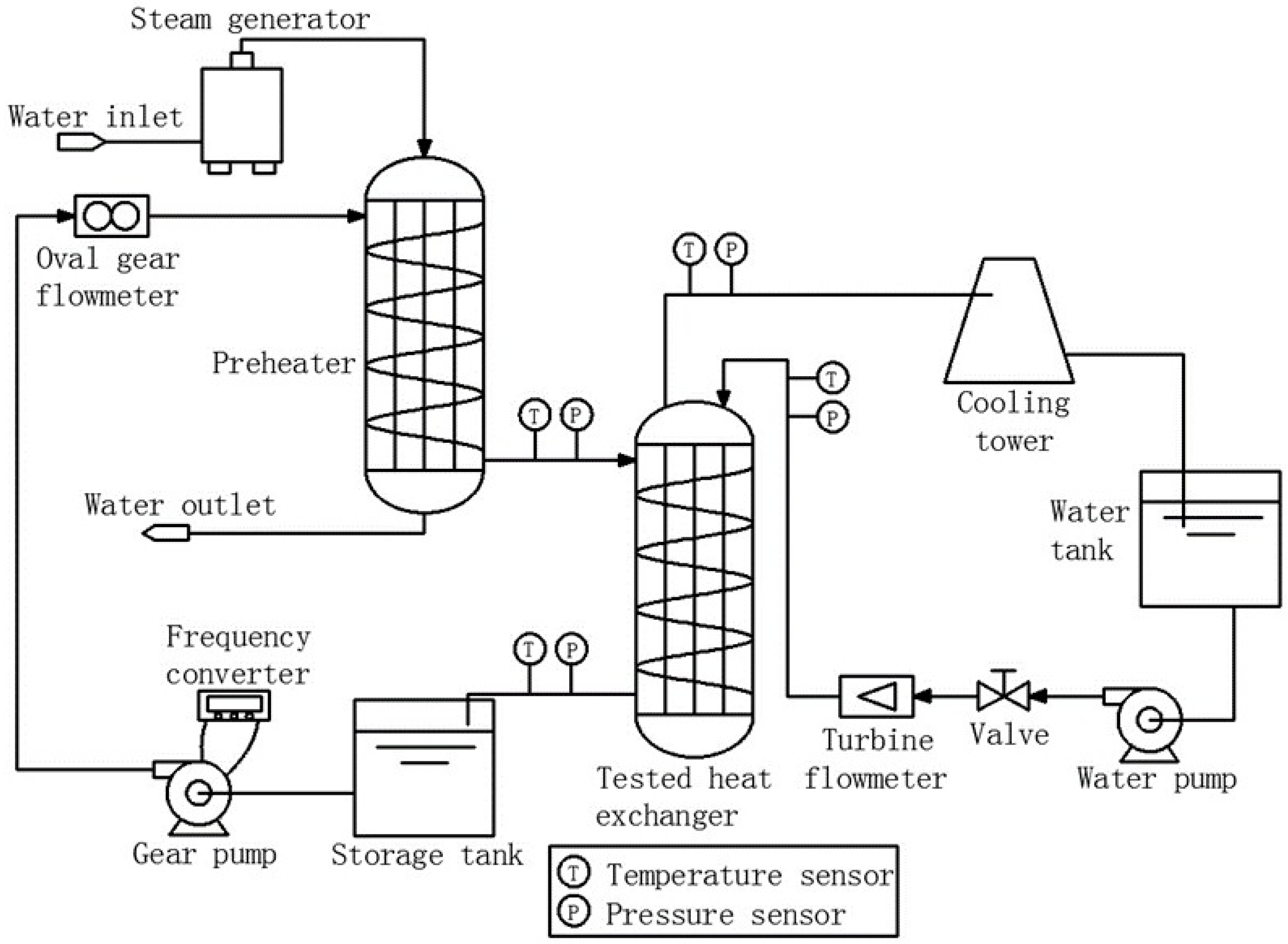
2.2. Experimental System

As shown in Figure 1, an experimental to study the non-Newtonian nanofluids flowing in shell side of helical baffled heat exchanger combined with elliptic tubes was carried out using the same experimental apparatus described in [28]. It consists of three parts, a non-Newtonian nanofluid loop, a coolant (water) loop and a data acquisition system. In the non-Newtonian nanofluid loop, the non-Newtonian nanofluid is heated in a preheater before being cooled by cooling water in the tested heat exchanger. While in the coolant loop, a cooling tower is adopted to cool the hot water from tested heat exchanger after heat exchange with non-Newtonian nanofluid. All the experiment details can be referred to [28]. In this work, the uncertainties in the measurements will be reported since they vary a little depending upon the fluid tested, even if the same apparatus is employed. The volume flow rate of non-Newtonian nanofluids flowing in the shell side ranged from 1.2 to 1.8 m3·h−1, with the maximum velocity of non-Newtonian nanofluids in the shell side ranging from 1.3 to 1.9 m·s−1. Generally, the maximum velocity in shell side of the shell and tube heat exchanger was lower than 2.0 m·s−1 for high viscosity fluids due to the limitation of pressure drop. The flow rate of water coolant flowing in tube was maintained constant at 1.95 m3·h−1. The inlet temperature of non-Newtonian nanofluids was held at 65 ± 0.1 °C. The inlet temperature of water coolant was kept at 30 ± 0.1 °C. Both the temperature and pressure data are recorded by Agilent 34970A data system (Santa Clara, CA, USA). The program was initiated to scan 10 times over a period of 15 min for each data point. All measurements were arithmetically averaged.

2.3. Data Reduction

The average heat transfer rate Qave is adapted to calculate the overall heat transfer coefficient based on outer surface area Ao by using the logarithmic mean temperature difference (LMTD).
U o = Q ave A o F T L M T D
L M T D = ( T s , in T t , out ) ( T s , out T t , in ) ln [ ( T s , in T t , out ) / ( T s , out T t , in ) ]
where FT is correction factor based on one shell pass and four tube passes heat exchanger design, 0.89.
The tested heat exchanger is fresh new, thus the influence of fouling resistance is neglected. The shell-side heat transfer coefficient can be obtained by thermal-resistance separation method:
h o = ( 1 U o d eo 2 λ wall ln d eo d ei A o A i 1 h i ) 1
where λwall is the thermal conductivity of tube wall made from stainless steel, 16.2 W·m−1·K−1.
Depending on the shell-side heat transfer coefficient ho and pressure drop ΔPo, the shell-side Nusselt number Nuo, friction factor fo and Euler number Euo can be calculated from the following equations [28]:
N u o = h o d eo λ f
f o = Δ P o 2 ρ f u max 2 B l
E u o = Δ P o ρ f u max 2
where the equivalent inside and outside diameter of the tube, dei and deo, and the maximum velocity in shell side umax can be obtained from [28].
The uncertainties of overall heat transfer coefficient Uo, Nusselt number Nuo, friction factor fo and Euler number Euo were estimated by the method suggested by Kline and McClintock [29] as follow and turned out to be less than 3.7%, 4.2%, 4.8% and 4.3%, respectively.
W R = ( R x 1 W x 1 ) 2 + ( R x 2 W x 2 ) 2 + + ( R x n W x n ) 2
where R and xn are the variable affecting the results of R. WR is the contribution to the uncertainty in the results from xn.

3. Mathematical Modeling
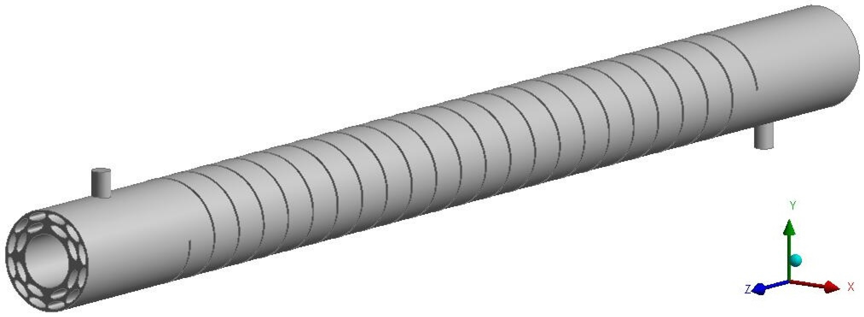
3.1. Physical Model

In the present study, the experimental and numerical investigations of the XG solution and its nanofluids flowing in the shell side of the helical baffle heat exchanger with elliptic tubes were conducted. The geometrical parameters of the physical model for the numerical simulation are the same with experimental model. Considering the complexity of heat exchanger and the convergence of simulation, both the xanthan gum solution and its nanofluids are considered single-phase fluid in the whole numerical simulation. Thus, the single-phase flow model is adopted to simulate the flow and heat transfer characteristics of non-Newtonian nanofluids in shell side of tested heat exchanger.
In order to simplify the numerical simulation while still keep the accuracy of results, necessary and reasonable assumptions are made as follows: (1) the experiment was initiated to scan data point while the system reached a steady state, thus the fluid flow and heat transfer in shell side are in fully turbulent flow and steady-state; (2) the MWCNTs dispersed homogeneously in the base fluid, the nanofluid in shell side can be consider as single-phase fluid; (3) the heat exchanger is covered with thermal insulation layer so that it is well insulated; (4) the natural convection in working fluid is neglected; and (5) the baffles are adiabatic.

3.2. Governing Equations and Numerical Method

The commercial software FLUENT was used to simulate the flow and heat transfer characteristic in the shell side. The realizable k-ε model was adopted to the numerical simulation [30]. The governing equation for the mass, momentum, energy conservations, and for turbulent kinetic energy k and turbulent energy dissipation ε can be expressed as follows [28,31,32]:
Continuity equation:
u i x i = 0
Momentum equation:
u i u j x i = 1 ρ P x i + x j [ ( v + v τ ) ( u j x i + u i x j ) ]
Energy equation:
u i T x i = ρ x i [ ( v P r + v τ P r τ ) T x i ]
Turbulent kinetic energy equation:
t ( ρ k ) + x j ( ρ k u j ) = x j [ ( v + v τ σ k ) k x j ] + Γ ε
Turbulent energy dissipation equation:
t ( ρ ε ) + x j ( ρ ε u j ) = x j [ ( v + v τ σ ε ) ε x j ] + C 1 Γ ε C 2 ε 2 k + v ε
where Γ = u i u j ¯ u i x i = v τ ( u i x j + u j x i ) u i x i , v τ = ρ C μ k 2 ε .
The model constants have been established to ensure that the model performs well for certain canonical flow as follows:
C 1 = max [ 0.43 , η η τ + 5 ] ,   C 2 = 1.0 ,   σ k = 1.0 ,   σ ε = 1.2
where σk and σε are the Prandtl number for k and ε, respectively. The enhanced wall treatment was adopted for the compute of flow characteristic in the near-wall region. The range of the dimensionless length y+ is y+ ≤ 5.
The governing equations were based on finite volume method [33]. The SIMPLE algorithm was adopted for velocity-pressure coupling. The second order upwind scheme was used to discretize the convective terms. The convergence criterion was that the mass residual less than 10−4 and the energy less than 10−7. A parallel computation with 16 numbers of processes was performed on workstation with 32 Intel Xeon-core CPUs and 32 GB RAM. It takes approximately 36 h to acquire converged solutions.

3.3. Boundary Conditions

(1)
The inlet of shell side used the mass flow inlet boundary condition as follow:
M = V f ρ f   ( constant mass flow )
T = T s , i n   ( uniform inlet temperature )
(2)
The outlet shell side used the pressure outlet boundary condition as follow:
u n = v n = w n = 0 ,   T n = 0
where n is the normal vector of outlet. The outlet temperature and pressure results of calculation were obtained from this plane.
(3)
The adiabatic wall boundary conditions were adopted for the shell walls and baffle walls:
u = v = w = 0 ,   T n = 0

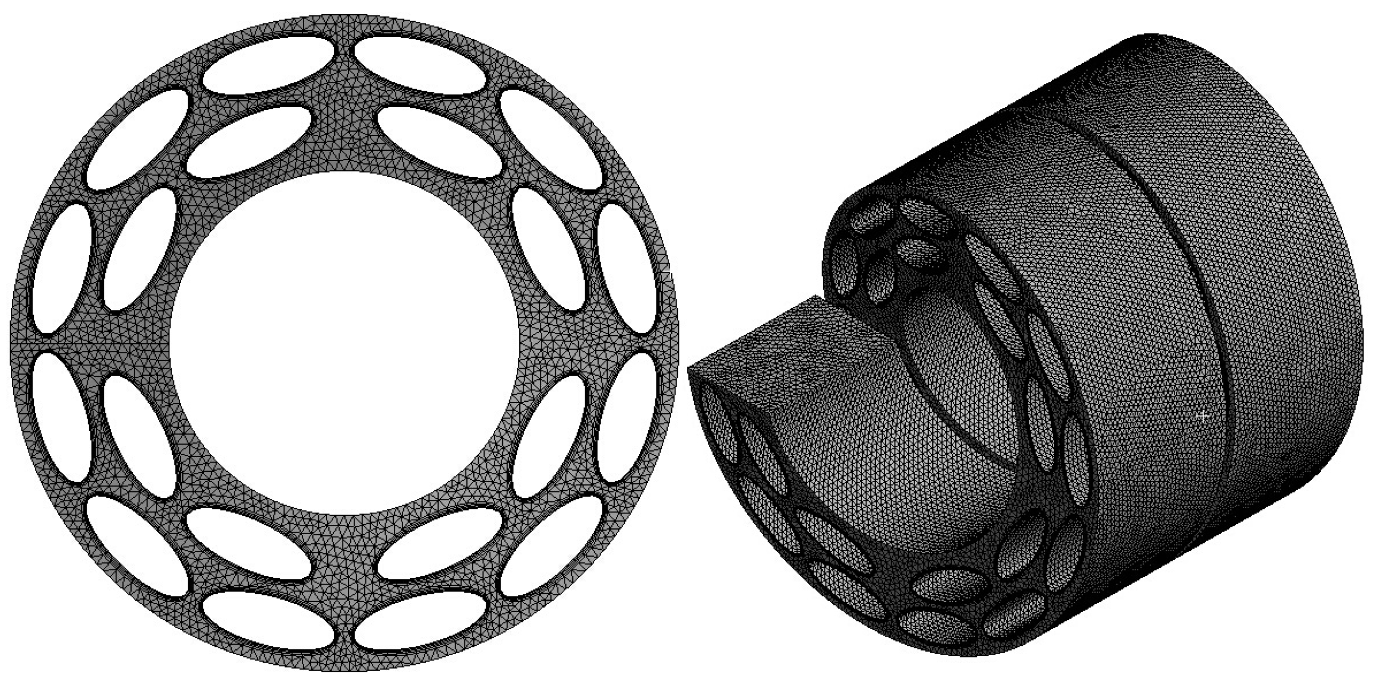
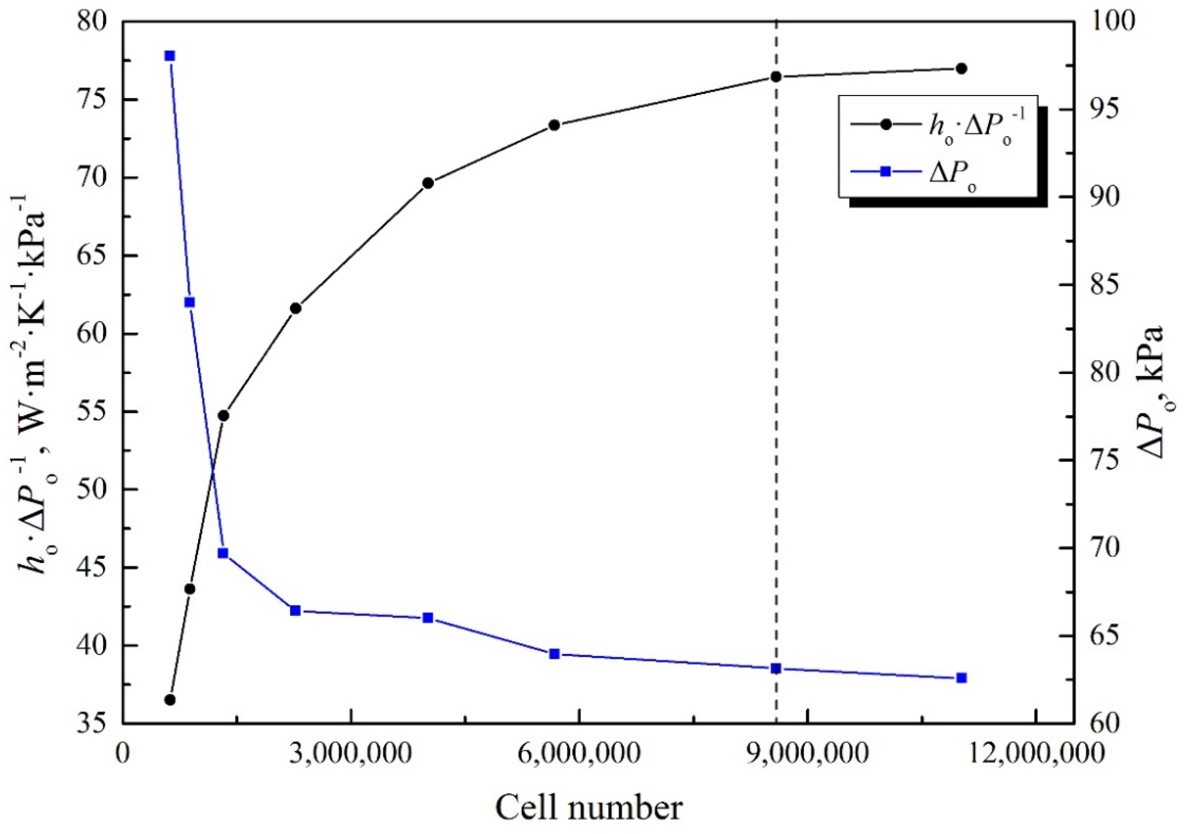
3.4. Grid Generation and Independence

The 3D geometry shown in Figure 2 was built using commercial CAD program. Due to the complicated structure of the shell side, the tetrahedral grid was elected to mesh computational domain, as shown in Figure 3. A careful check for grid independence was conducted to obtain accurate simulation results as shown in Figure 4. It is found that the relative deviation of pressure drop ΔPo and heat transfer coefficient per unit pressure drop ho·ΔPo−1 between 8.6 × 10⁶ and 1.1 × 10⁷ grid cells are both less than 1.0%. Considering time cost, solution accuracy and memory space, the grid system of 8.6 × 10⁶ cells was taken for the whole numerical simulation.

4. Results and Discussion

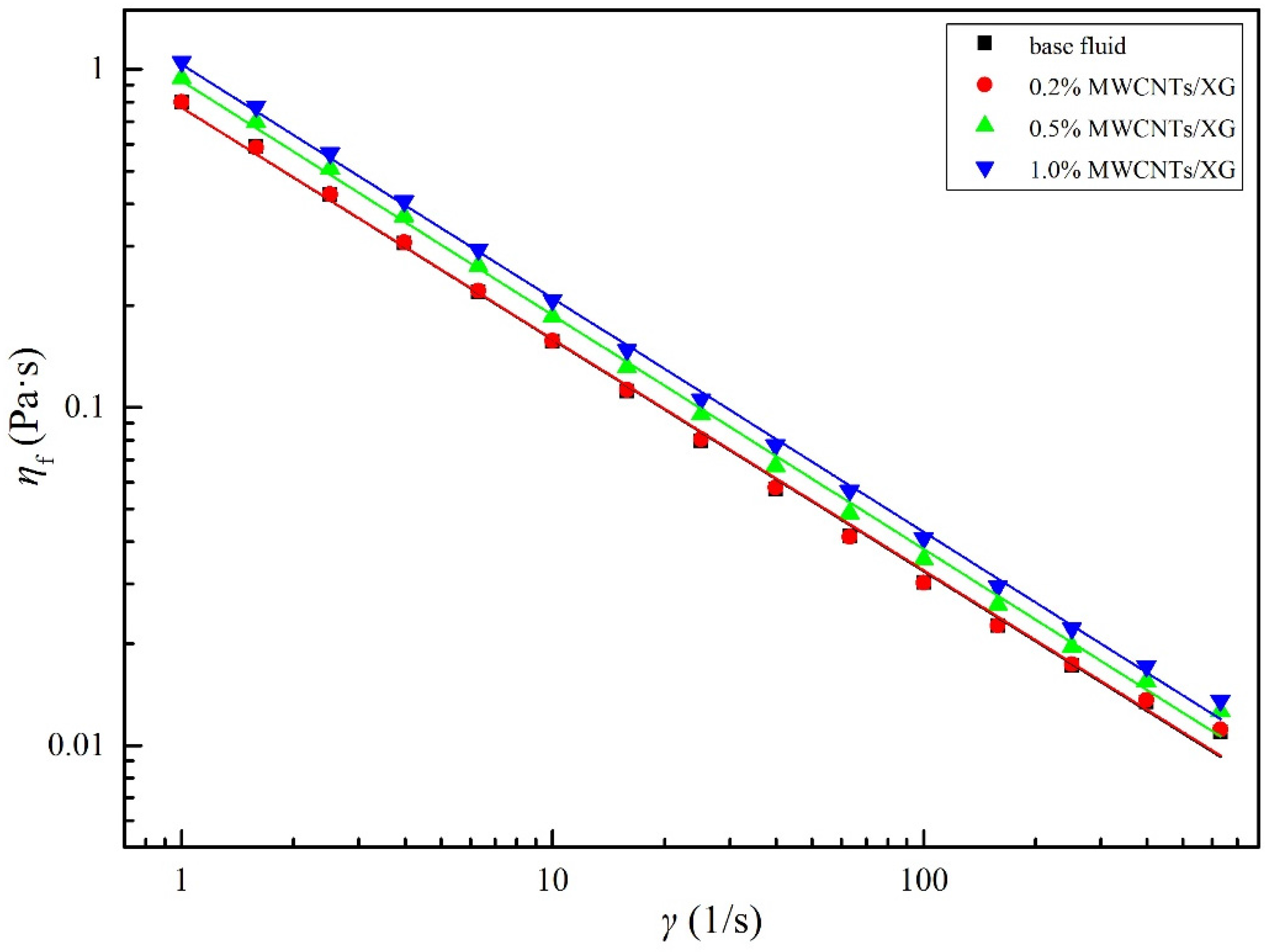
4.1. Thermal-Physical Properties of Non-Newtonian Nanofluids

Figure 5 shows the variation of the viscosity η of base fluid and nanofluids with the shear rate γ at 25 °C. As can be seen from Figure 5, the viscosities of all working fluids decreases with the increasing of the shear rate, indicating that all the samples are typical non-Newtonian fluids with shear thinning behavior (n < 1). For a given shear rate γ, the viscosity increases slightly with the increase in weight fraction of nanoparticle.
Thermal-physical properties of base fluid and non-Newtonian nanofluids including consistency index K, power law index n, thermal conductivity λ, density ρ and specific heat cp were measured and their correlations to temperature are provided in Table 1.

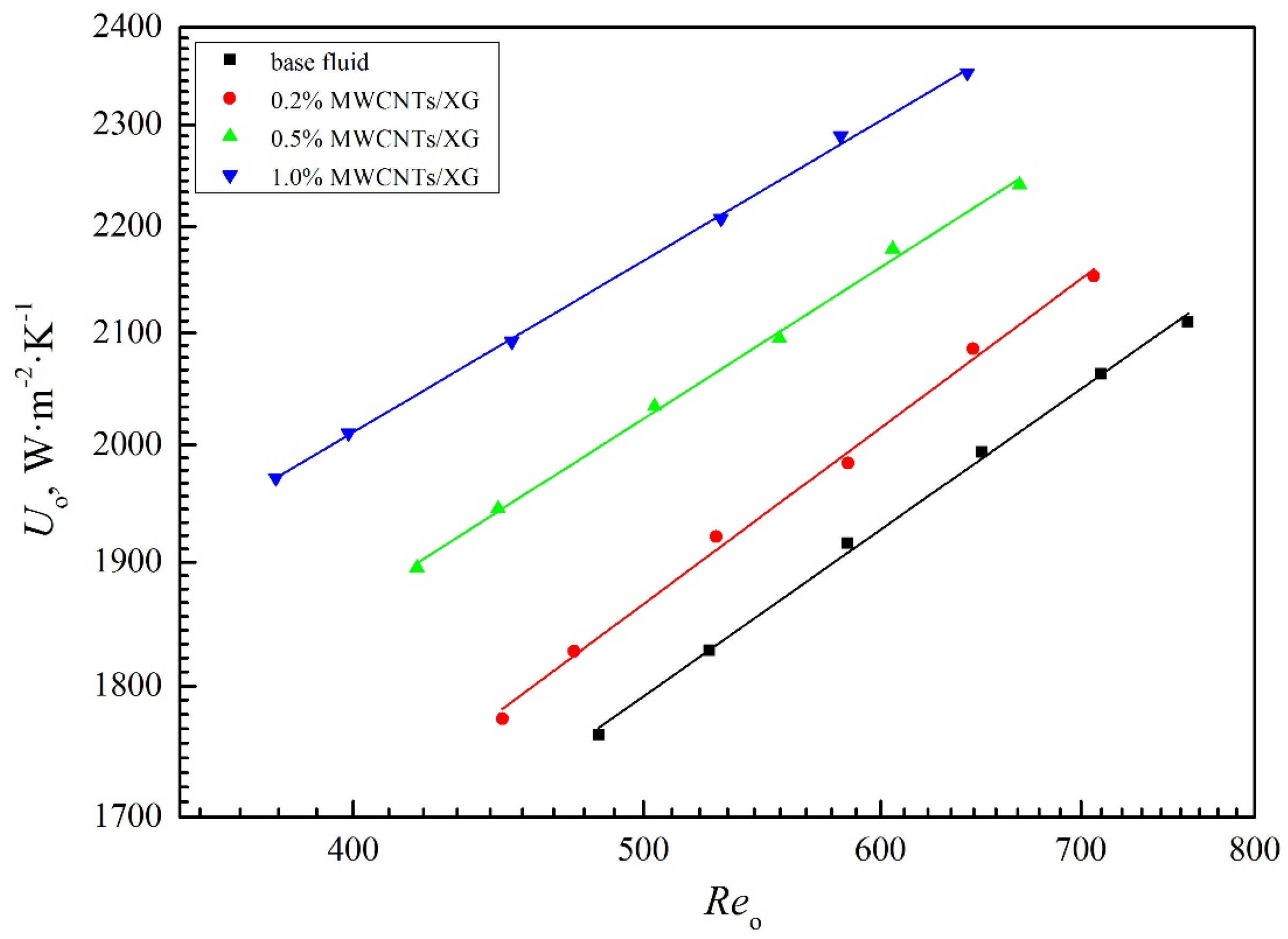
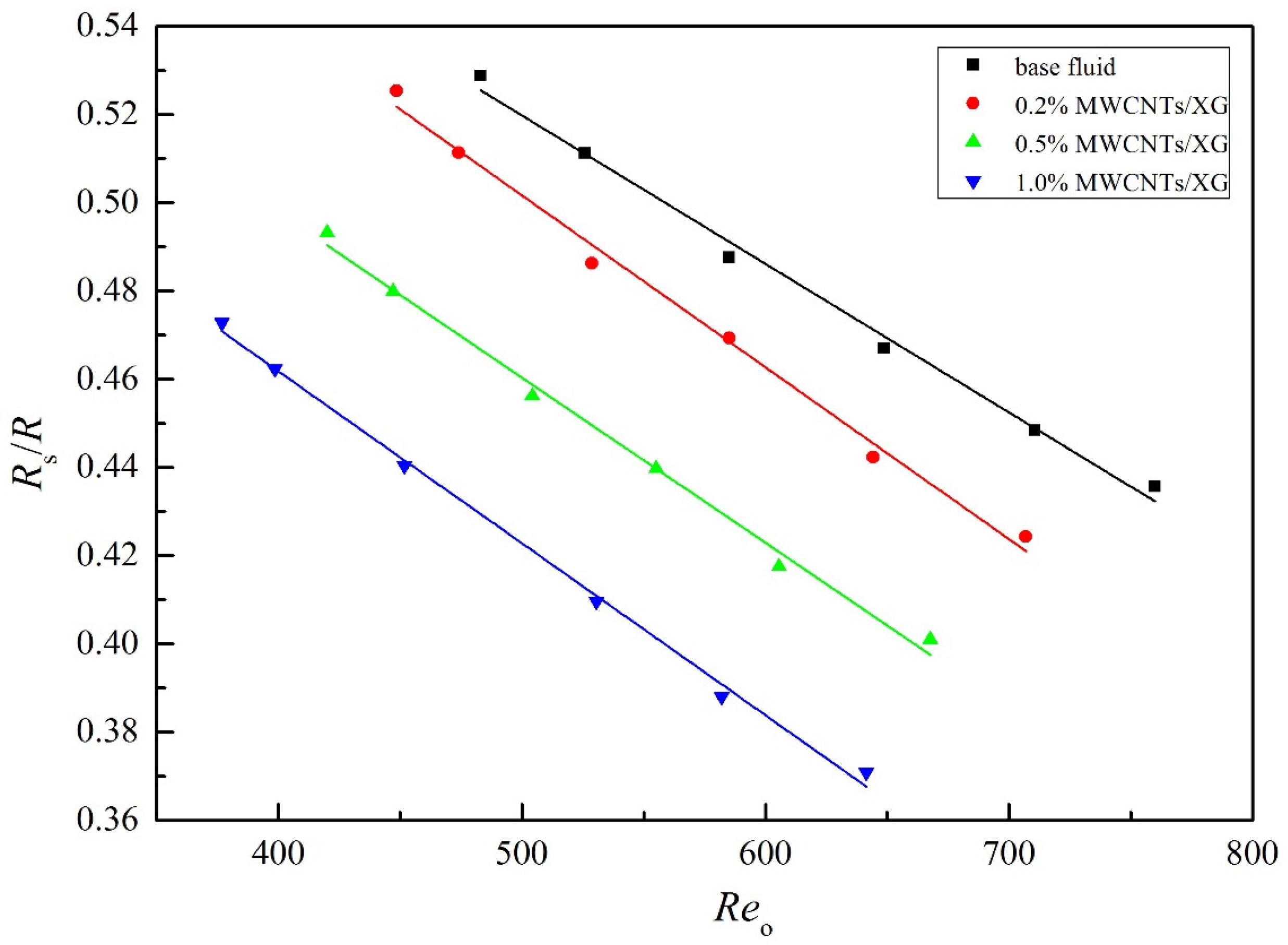
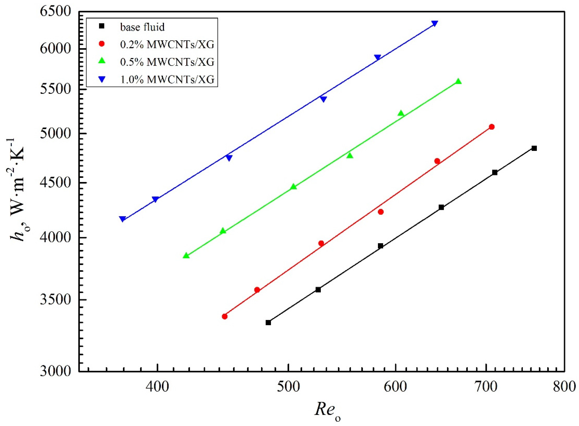
4.2. Overall and Shell-Side Heat Transfer Coefficient

Figure 6 shows the variation of the overall heat transfer coefficient Uo with the shell-side Reynolds number Reo of non-Newtonian base fluid and its nanofluids at different concentrations. As can be seen from Figure 6, Uo increases remarkably with the increasing of Reo and MWCNTs concentration from 0.2 wt % to 1.0 wt %. For a given Reo, it can be found that the Uo of the non-Newtonian nanofluids at weight fractions of 1.0 wt %, 0.5 wt % and 0.2 wt % increase by 22%, 14% and 6% on average, respectively. Similar trend can also be observed in shell-side heat transfer coefficient ho shown in Figure 7. It is apparent that the addition of MWCNTs enhances the shell-side heat transfer performance of heat exchanger.
Figure 8 presents the thermal resistance analysis of tested heat exchanger for the non-Newtonian base fluid and its nanofluids at different concentrations. Rs and R are the shell-side and overall thermal resistances given as follows:
R s = h o 1
R = U o 1
As can be seen from Figure 8, the ratio of shell-side thermal resistance to overall thermal resistance decreases with the increasing in both shell-side Reynolds number and weight fraction of MWCNTs. In comparison to the base fluid, the thermal resistance ratio of the nanofluids with 0.2 wt %, 0.5 wt %, and 1.0 wt % MWCNTs decrease approximately 4%, 16%, and 20% at the same Reynolds number. Thus, the addition of MWCNTs into base fluid significantly increases the heat transfer coefficient in the shell side.

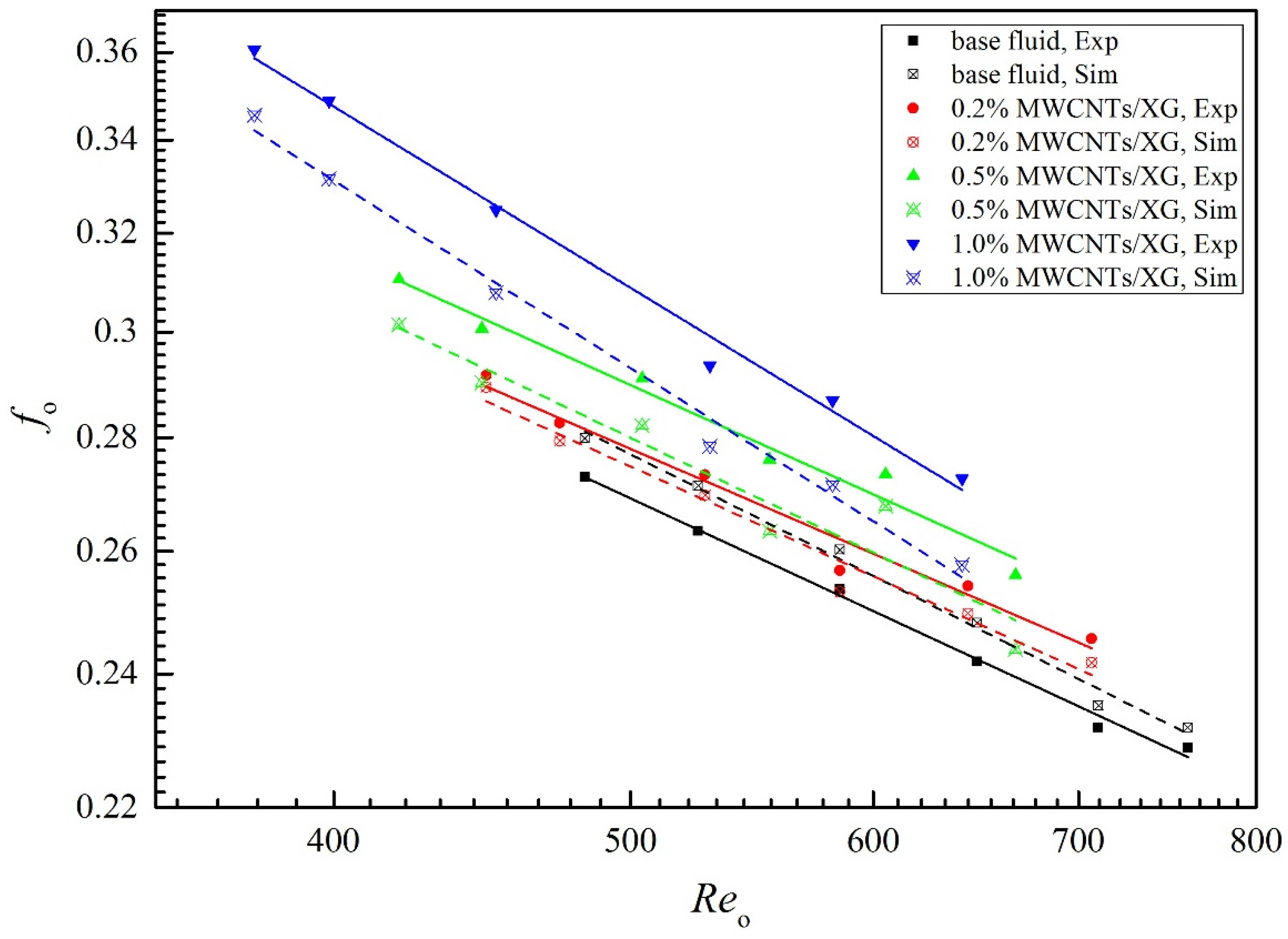
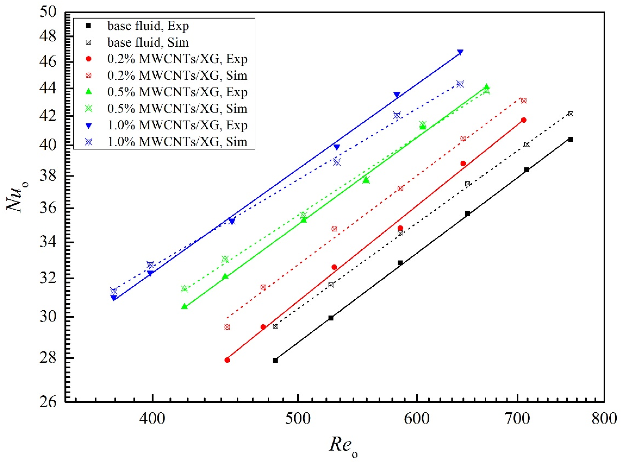
4.3. Nusselt Number and Friction Factor

Based on experimental and numerical results, Figure 9 and Figure 10 show the variation of the shell-side Nusselt number Nuo and friction factor fo with the Reynolds number Reo for the base fluid and nanofluids at different concentrations, respectively. From Figure 9, it is found that Nuo increases with the increasing of Reo. For a given Reo, Nuo increases with an increasing in the MWCNTs concentration. Based on experimental data, the Nuo of the non-Newtonian nanofluids at weight fraction of 1.0 wt %, 0.5 wt %, and 0.2 wt % increases by 35%, 21% and 11% on average while compared with that of the base fluid at the same Reynolds number Reo, respectively. It can be observed from Figure 10 that the experimental fo of the nanofluids are larger than that of the base fluid, and gradually increases with increasing in the weight fraction of nanoparticles and rapidly decreases with an increase in Reo. Higher friction factor leads to greater pressure drop in shell side, which is the obvious drawback of nanofluid. The enhanced thermal conductivity and viscosity of nanofluid after adding MWCNTs are response for the increasing of Nuo and fo, respectively.
Both Figure 9 and Figure 10 show that the simulation results fit very well with experimental data. The average deviations between experimental and numerical data are listed in Table 2. As can be seen in Table 2, the average deviations between numerical and experimental results are less than 6%, indicating that the single-phase flow model is able to simulate the heat transfer and flow characteristic of non-Newtonian base fluid and its nanofluids in shell side. However, with the increasing in weight fraction of nanoparticles, the values of Nuo and fo from simulation are less than those from experiment, indicating that the Brownian motion of nanoparticles and the interaction between nanoparticles and base fluid are other reasons for the enhancement of Nuo and fo [23], which are neglected in single-phase flow model. It can be predicted that the sing-phase flow model can effectively simulate the flow and heat transfer of nanofluids at low concentration because, in this case, the improvements of thermal properties are the main driver for the heat transfer enhancement, while, with the increasing of nanoparticles concentration, the Brownian motion of nanoparticles and the interaction between nanoparticles and base fluid play increasingly important role in the processes of flow and heat transfer. The nanofluid tends to be two-phase flow, which should be simulated by multi-phase flow model for higher precision.
Based on the results of numerical simulations, the local (Z = −500 mm) temperature distributions of base fluid and nanofluids in helical baffled heat exchanger with elliptic tubes at Vf = 1.72 m3·h−1 are shown in Figure 11a–d. As shown in Figure 11, the temperature along the flow drops more slowly compared with nanofluids. As the concentrations of nanoparticles increase, lower temperature can be observed at the same position of heat exchanger due to the enhanced thermal conductivities after the addition of MWCNTs.

4.4. Euler Number

Figure 12 shows the variation of Euler number Euo with Reynolds number Reo in double logarithm coordinate. As shown in Figure 12, Euo decreases with the increasing in Reo and the decreasing in nanoparticle weight fraction. For a given Reo, the Euo of nanofluids at weight fraction of 1.0 wt %, 0.5 wt %, and 0.2 wt % increases by 16%, 7.6% and 3.1% in comparison with base fluid, respectively.

4.5. Correlations

Based on experimental results, the following correlations are fitted for the shell-side Nusselt number, friction factor and Euler number of non-Newtonian nanofluids flowing in the shell side of elliptic tube heat exchanger with helical baffles.
N u o = a R e o b P r o 1 / 3 ( 1 + φ c )
f o = a R e o b ( 1 + φ c )
E u o = a R e o b ( 1 + φ c )
The predicted values and maximum deviations of aforementioned correlations are listed in Table 3. Good agreements exists between the correlations and experimental data.
Equations (15)–(17) are suggested for the ranges of Reo, Pro and ϕ as following:
370 R e o 760 ;   90 P r o 110 ;   0 φ 1.0 %

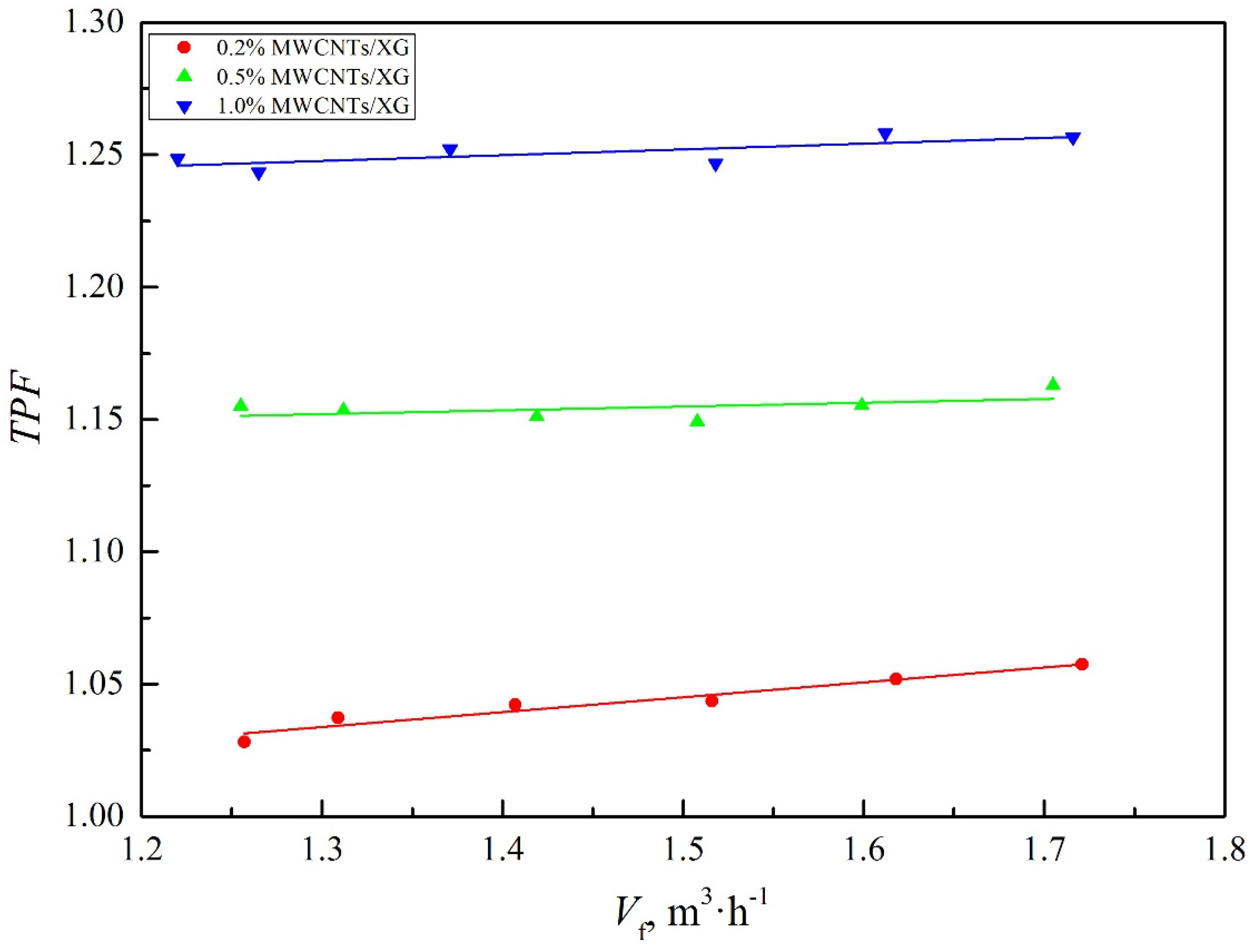
4.6. Comprehensive Performance

Considering both heat transfer performance and flow resistance characteristic, the comprehensive thermal performance factor (TPF) is adopted to evaluate the heat exchanger. TPF is calculated using the following equation [34]:
T P F = ( j o / f o 1 / 3 ) n f ( j o / f o 1 / 3 ) b f
j o = N u o R e o P r o 1 / 3
where subscripts nf and bf represent nanofluids and base fluid, respectively.
If the value of TPF is higher than 1.0, the integrative performance of the nanofluid is enhanced in comparison with the base fluid by the addition of nanoparticle, and higher value is preferred. Figure 13 shows the variation trend of the thermal performance factor versus volume flow rate. As can be seen from Figure 13, the values of nanofluid with different mass fraction are all higher than 1.0. Compared with the base fluid, the comprehensive performances of the 0.2 wt %, 0.5 wt % and 1.0 wt % nanofluid are enhanced significantly, by 3%–5%, 15%–17% and 24%–26%, respectively.

5. Conclusions

This paper presents the experimental and numerical work carried out to compare the heat transfer coefficients, Nusselt number, friction factor, Euler number and comprehensive thermal performance factor of non-Newtonian base fluid and its nanofluids in a helically baffled heat exchanger with elliptic tubes. The main conclusions are summarized as follows:
(1)
Experiment results have proven that the accuracy of numerical simulation model is satisfactory. Good agreements exist between experimental and numerical data. The single-phase flow model can simulate the flow and heat transfer characteristic of non-Newtonian nanofluids at low concentration.
(2)
The heat transfer is significantly enhanced by adding nanoparticle compared to base fluid. The overall and shell-side heat transfer coefficients of nanofluids are higher than those of base fluid at the same Reynolds number. The enhancement in heat transfer coefficient increases with the increasing in the weight fraction of MWCNTs.
(3)
The Nuo, fo, Euo increase with the increasing in the weight fraction of nanoparticle at the same Reynolds number. In the whole range of volume flow rate, the TPF of nanofluids are all higher than 1.0. The changes in flow and heat characteristic of nanofluids can be attributed to the enhanced thermal conductivities and viscosities.
(4)
Correlations for predicting the shell-side Nusselt number, friction factor and Euler number of non-Newtonian nanofluids in the helically baffled heat exchanger with elliptic tubes were obtained based on experimental results, and fitted the data very well.

Acknowledgments

This work was supported by the National Natural Science Foundation of China (51276066), Guangdong Natural Science Foundation (2014A030312009) and the Fundamental Research Funds for the Central Universities (2015ZP006).

Author Contributions

Ziye Ling wrote the paper; Zhenbin He made the numerical study; Tao Xu performed the experiment; Xuenong Gao and Xiaoming Fang analyzed the data; and Zhengguo Zhang conceived and designed the experiment.

Conflicts of Interest

The authors declare no conflict of interest.
Nomenclature
  a, b, ccoefficients in corrections
  Asurface area (m2)
  Bbaffle spacing (m)
  C1, C2coefficients in k-ε turbulence model
  EuEuler number
  ffriction factor
  FTcorrection factor
  jj-factor
  kturbulent fluctuation kinetic energy (m2·s−2)
  Kconsistency index (Pa·sn)
  llength of tube (m)
  Mmass flow rate (kg·s−1)
  npower law index
  NuNusselt number
  Ppressure (Pa)
  PrPrandtl number
  reffect variable
  Rthermal resistance (m2·K−1·W−1)
  ReReynolds number
  Ttemperature (K)
  TPFthermal performance factor
  u, v, wvelocity (m·s−1)
  Uooverall heat transfer coefficient based on Ao (W·m−2·K−1)
  Vvolume flow rate (m3·s−1)
  xneffect variable
  x, y, zcoordinate (mm)
  y+dimensionless distance from the wall
Greek Symbol
  ρdensity (kg·m−3)
  ηdynamic viscosity (Pa·s)
  νkinematic viscosity (m2·s−1)
  λthermal conductivity (W·m−1·K−1)
  τturbulent kinematic viscosity (m2·s−1)
  εturbulent kinetic energy dissipation rate (m2·s−3)
  δwall thickness (mm)
  σkPrandtl number for k
  σεPrandtl number for ε
  γshear rate (s−1)
  ζheat balance deviation
  ϕweight fraction of nanoparticle
  Δdifference
Subscripts
  bfbase fluid
  fnon-Newtonian fluid
  iinside
  ininlet
  maxmaximum
  nfnanofluid
  ooutside
  walltube wall

References

  1. Kasaeian, A.; Eshghi, A.T.; Sameti, M. A review on the applications of nanofluids in solar energy systems. Int. J. Heat Mass Transf. 2015, 43, 584–598. [Google Scholar] [CrossRef]
  2. Mohammadian, S.K.; Seyf, H.R.; Zhang, Y. Performance augmentation and optimization of aluminum oxide-water nanofluid flow in a two-fluid microchannel heat exchanger. J. Heat Transf. Trans. ASME 2014, 136, 228–240. [Google Scholar] [CrossRef]
  3. Ghanbarpour, M.; Haghigi, E.B.; Khodabandeh, R. Thermal properties and rheological behavior of water based Al2O3 nanofluid as a heat transfer fluid. Exp. Therm. Fluid Sci. 2014, 53, 227–235. [Google Scholar] [CrossRef]
  4. Mahian, O.; Kianifar, A.; Kleinstreuer, C.; Al-Nimr, M.A.; Pop, I.; Sahin, A.Z. A review of entropy generation in nanofluid flow. Int. J. Heat Mass Transf. 2013, 65, 514–532. [Google Scholar] [CrossRef]
  5. Hussein, A.M.; Sharma, K.V.; Bakar, R.A.; Kadirgama, K. A review of forced convection heat transfer enhancement and hydrodynamic characteristics of a nanofluid. Renew. Sustain. Energy Rev. 2014, 29, 734–743. [Google Scholar] [CrossRef]
  6. Choi, S.U.S.; Eastman, J.A. Enhancing thermal conductivity of fluids with nanoparticles, International mechanical engineering congress and exhibition. ASME 1995, 231, 12–17. [Google Scholar]
  7. Sheikholeslami, M.; Ellahi, R. Electrohydrodynamic nanofluid hydrothermal treatment in an enclosure with snusoidal upper wall. Appl. Sci. 2015, 5, 294–306. [Google Scholar] [CrossRef]
  8. Sheikholeslami, M.; Zia, Q.M.Z.; Ellahi, R. Influence of induced magnetic field on free convection of nanofluid considering Koo-Kleinstreuer-Li (KKL) correlation. Appl. Sci. 2016, 6, 324. [Google Scholar] [CrossRef]
  9. Rahman, S.U. Simultaneous effects of nanoparticles and slip on Jeffrey fluid through tapered artery with mild stenosis. J. Mol. Liq. 2016, 218, 484–493. [Google Scholar] [CrossRef]
  10. Akbarzadeh, M. A sensitivity analysis on thermal and pumping power for the flow of nanofluid inside a wavy channel. J. Mol. Liq. 2016, 220, 1–13. [Google Scholar] [CrossRef]
  11. Sheikholeslami, M.; Ellahi, R. Three dimensional mesoscopic simulation of magnetic field effect on natural convection of nanofluid. Int. J. Heat Mass Transf. 2015, 89, 799–808. [Google Scholar] [CrossRef]
  12. Ellahi, R.; Hassan, M.; Zeeshan, A. Shape effects of nanosize particles in Cu–H2O mathContainer loading mathjax, nanofluid on entropy generation. Int. J. Heat Mass Transf. 2015, 81, 449–456. [Google Scholar] [CrossRef]
  13. Sheikholeslami, M. Effect of thermal radiation on magnetohydrodynamics nanofluid flow and heat transfer by means of two phase model. J. Magn. Magn. Mater. 2015, 374, 36–43. [Google Scholar] [CrossRef]
  14. Rashidi, S. Study of stream wise transverse magnetic fluid flow with heat transfer around an obstacle embedded in a porous medium. J. Magn. Magn. Mater. 2015, 378, 128–137. [Google Scholar] [CrossRef]
  15. Ellahi, R.; Hassan, M.; Zeeshan, A. Study of natural convection MHD nanofluid by means of single and multi-walled carbon nanotubes suspended in a salt-water solution. IEEE Trans. Nanotechnol. 2015, 14, 726–734. [Google Scholar] [CrossRef]
  16. Kandelousi, M.S.; Ellahi, R. Simulation of ferrofluid flow for magnetic drug targeting using the lattice boltzmann method. Z. Neuropsychol. A 2015, 70, 115–124. [Google Scholar] [CrossRef]
  17. Akbar, N.S.; Raza, M.; Ellahi, R. Influence of induced magnetic field and heat flux with the suspension of carbon nanotubes for the peristaltic flow in a permeable channel. J. Magn. Magn. Mater. 2015, 381, 405–415. [Google Scholar] [CrossRef]
  18. Ellahi, R.; Hassan, M.; Zeeshan, A. Aggregation effects on water base Al2O3 nanofluid over permeable wedge in mixed convection. Asia Pac. J. Chem. Eng. 2016, 76, 3825–3835. [Google Scholar] [CrossRef]
  19. Mamourian, M. Optimization of mixed convection heat transfer with entropy generation in a wavy surface square lid-driven cavity by means of Taguchi approach. Int. J. Heat Mass Transf. 2016, 102, 544–554. [Google Scholar] [CrossRef]
  20. Ellahi, R.; Zeeshan, A.; Hassan, M. Particle shape effects on Marangoni convection boundary layer flow of a nanofluid. Int. J. Numer. Methods Heat Fluid Flow 2016, 26, 2160–2174. [Google Scholar] [CrossRef]
  21. Chhabra, R.P.; Richardson, J.F. Non-Newtonian Flow and Applied Rheology: Engineering Applications; Butterworth-Heinemann: London, UK, 2008. [Google Scholar]
  22. Tian, J.; He, Z.B.; Xu, T.; Fang, X.M.; Zhang, Z.G. Rheological Property and Thermal Conductivity of Multi-walled Carbon Nanotubes-dispersed Non-Newtonian Nanofluids Based on an Aqueous Solution of Carboxymethyl Cellulose. Exp. Heat Transf. 2015. [Google Scholar] [CrossRef]
  23. Hojjat, M.; Etemad, S.G.; Bagheri, R.; Thibault, J. Turbulent forced convection heat transfer of non-newtonian nanofluids. Exp. Therm. Fluid Sci. 2011, 35, 1351–1356. [Google Scholar] [CrossRef]
  24. Kral, D.; Stehlik, P.; Van Der Ploeg, H.; Master, B.I. Helical baffles in shell-and-tube heat exchangers, Part I: Experimental verification. Heat Transf. Eng. 1996, 17, 93–101. [Google Scholar] [CrossRef]
  25. Zhang, Z.G.; Li, Q.X.; Xu, T.; Fang, X.M.; Gao, X.N. Condensation heat transfer characteristics of zeotropic refrigerant mixture R407C on single, three-row petal-shaped finned tubes and helically baffled condenser. Appl. Therm. Eng. 2012, 39, 63–69. [Google Scholar] [CrossRef]
  26. Zhang, Z.G.; Ma, D.B.; Fang, X.M.; Gao, X.N. Experimental and numerical heat transfer in a helically baffled heat exchanger combined with one three-dimensional finned tube. Chem. Eng. Process. 2008, 47, 1738–1743. [Google Scholar] [CrossRef]
  27. Zhang, Z.G.; Wu, C.S.; Fang, X.M.; Gao, X.N.; Wang, Z.Y. Experimental study of shell-side heat transfer coefficient and pressure drop for an integrally helical baffled heat exchanger combined with different enhanced tubes. Ind. Eng. Chem. Res. 2009, 48, 4040–4044. [Google Scholar] [CrossRef]
  28. He, Z.B.; Fang, X.M.; Zhang, Z.G.; Gao, X.N. Numerical investigation on performance comparison of non-Newtonian fluid flow in vertical heat exchangers combined helical baffle with elliptic and circular tubes. Appl. Therm. Eng. 2016, 100, 84–97. [Google Scholar] [CrossRef]
  29. Kline, S.J.; McClintock, F.A. Describing uncertainties in single-sample experiments. Mech. Eng. 1953, 75, 3–8. [Google Scholar]
  30. Shih, T.H.; Liou, W.W.; Shabbir, A.; Yang, Z.; Zhu, J. A new k-ε eddy viscosity model for high reynolds number turbulent flows. Comput. Fluids 1995, 24, 227–238. [Google Scholar] [CrossRef]
  31. F. Inc. FLUENT 6.3 User’s Guide; F. Inc.: Pittsburgh, PA, USA, 2006. [Google Scholar]
  32. Dong, C.; Chen, Y.P.; Wu, J.F. Flow and heat transfer performances of helical baffle heat exchangers with different baffle configurations. Appl. Therm. Eng. 2015, 80, 328–338. [Google Scholar] [CrossRef]
  33. Tao, W.Q. Numerical Heat Transfer; Xi’an Jiaotong University Press: Xi’an, China, 2001. [Google Scholar]
  34. Xu, K.; Bo, R.; Meng, H. A thermal performance factor for evaluation of active engine cooling with asymmetric heating. Appl. Therm. Eng. 2014, 73, 351–356. [Google Scholar] [CrossRef]
Figure 1. Schematic diagram of heat transfer experimental set-up.
Applsci 07 00048 g001
Figure 2. 3D geometry of tested heat exchanger.
Applsci 07 00048 g002
Figure 3. Meshes of numerical models.
Applsci 07 00048 g003
Figure 4. Results of different grid systems (base fluid, Reo = 480).
Applsci 07 00048 g004
Figure 5. Variation of the viscosity with the shear rate at different concentrations at 25 °C.
Applsci 07 00048 g005
Figure 6. Overall heat transfer coefficient versus shell-side Reynolds number.
Applsci 07 00048 g006
Figure 7. Shell-side heat transfer coefficient versus shell-side Reynolds number.
Applsci 07 00048 g007
Figure 8. Ratio of shell side thermal resistance to overall thermal resistance at different shell-side Reynolds number.
Applsci 07 00048 g008
Figure 9. Nusselt number based on experiment and simulation versus shell-side Reynolds number.
Applsci 07 00048 g009
Figure 10. Friction factor based on experiment and simulation versus shell-side Reynolds number.
Applsci 07 00048 g010
Figure 11. Shell-side temperature distributions of elliptic tube heat exchanger (Vf = 1.72 m3·h−1, Z = −500 mm): (a) base fluid; (b) 0.2 wt % MWCNTs/XG; (c) 0.5 wt % MWCNTs/XG; and (d) 1.0 wt % MWCNTs/XG.
Applsci 07 00048 g011
Figure 12. Euler number versus Reynolds number.
Applsci 07 00048 g012
Figure 13. Comprehensive thermal performance factor versus volume flow rate.
Applsci 07 00048 g013
Table 1. Expression of thermal-physical properties.
FluidCorrelations (298.15 K < T < 338.15 K)
K (m2·sn)nλ (W·m−1·K−1)ρ (kg·m−3)cp (kJ·kg−1·K−1)
Base fluid−0.0131T + 4.6322
(R2 = 0.999)
0.0043T − 0.9469
(R2 = 0.988)
0.0043T − 0.6265
(R2 = 0.979)
−0.0073T2 + 4.2840T + 382.8
(R2 = 0.991)
−2.7149 × 10 − 5T2 − 0.01189T + 4.8763
(R2 = 0.996)
0.2 wt % MWCNTs/XG−0.0124T + 4.4211
(R2 = 0.999)
0.0040T − 0.8517
(R2 = 0.989)
0.0035T − 0.4168
(R2 = 0.987)
−0.0067T2 + 3.8902T + 451.2
(R2 = 0.991)
−5.4948 × 10 − 5T2 + 0.04071T − 3.5919
(R2 = 0.991)
0.5 wt % MWCNTs/XG−0.0111T + 4.1513
(R2 = 0.992)
0.0025T − 0.3962
(R2 = 0.982)
0.0026T − 0.1468
(R2 = 0.995)
−0.0052T2 + 2.9004T + 611.5
(R2 = 0.990)
−3.9137 × 10 − 5T2 + 0.03135T − 2.3183
(R2 = 0.998)
1.0 wt % MWCNTs/XG−0.0130T + 4.8356
(R2 = 0.996)
0.0021T − 0.3016
(R2= 0.998)
0.0025T − 0.1473
(R2 = 0.988)
−0.0016T2 + 0.6362T + 965.2
(R2 = 0.987)
6.9542 × 10 − 5T2 − 0.04154T + 9.6727
(R2 = 0.972)
Table 2. Average deviations of Nuo and fo between experimental and numerical data.
Non-Dimensional NumberFluidAverage Deviation
NuoBase fluid5.11%
0.2 wt % MWCNTs/XG5.63%
0.5 wt % MWCNTs/XG1.17%
1.0 wt % MWCNTs/XG−1.14%
foBase fluid0.25%
0.2 wt % MWCNTs/XG0.60%
0.5 wt % MWCNTs/XG−0.62%
1.0 wt % MWCNTs/XG−5.06%
Table 3. Predicted values and deviations of the correlations.
CorrelationabcMaximum Deviation
Equation (15)0.02840.86920.30819.62%
Equation (16)4.8456−0.46500.44844.04%
Equation (17)310.17−0.46940.43644.66%

