Article

Investigations on the Effects of Vortex-Induced Vibration with Different Distributions of Lorentz Forces

Science and Technology on Transient Physics Laboratory, Nanjing University of Science and Technology, Nanjing 210094, China
*
Author to whom correspondence should be addressed.
Appl. Sci. 2017, 7(1), 61; https://doi.org/10.3390/app7010061
Submission received: 31 October 2016 / Revised: 2 December 2016 / Accepted: 3 January 2017 / Published: 7 January 2017

Abstract

:
The control of vortex-induced vibration (VIV) in shear flow with different distributions of Lorentz force is numerically investigated based on the stream function–vorticity equations in the exponential-polar coordinates exerted on moving cylinder for Re = 150. The cylinder motion equation coupled with the fluid, including the mathematical expressions of the lift force coefficient C l , is derived. The initial and boundary conditions as well as the hydrodynamic forces on the surface of cylinder are also formulated. The Lorentz force applied to suppress the VIV has no relationship with the flow field, and involves two categories, i.e., the field Lorentz force and the wall Lorentz force. With the application of symmetrical Lorentz forces, the symmetric field Lorentz force can amplify the drag, suppress the flow separation, decrease the lift fluctuation, and then suppress the VIV while the wall Lorentz force decreases the drag only. With the application of asymmetrical Lorentz forces, besides the above-mentioned effects, the field Lorentz force can increase additional lift induced by shear flow, whereas the wall Lorentz force can counteract the additional lift, which is dominated on the total effect.

1. Introduction

Bluff structures such as offshore spar, marine risers, overhead transmission lines and heat exchangers are subjected to vortex-induced vibration (VIV) when exposed to a flowing fluid, which contributes to the fatigue life reduction of structures and may produce structure damage under certain unfavorable conditions. The interactions between the shedding among various cylinders are much more complicated and they are also relevant to a number of problems. One of the problems where this is critical is concentrated solar power (CSP) collectors, where the shedding from one row affects the next one, leading to mechanical problems due to vibration and fatigue [1,2]. The vibrations arise from the time-periodic fluid force associated with the time-periodic shedding vortex, and subsequently alter the flow field, which will change the flow-induced force in turn. Such fluid–structure interactions increase the complexity of the fluid mechanisms.
Extensive research on VIV has been conducted. The earliest studies have been the subject of interests with lock-in phenomenon of VIV (e.g., [3,4,5,6,7,8,9,10]). The time varying parameters such as cylinder response, flow force, vortex shedding and the influences of cylinder motion on the vortex structure are further studied [11,12,13,14], and the vortex-formation modes have been focused on later by [15,16,17,18], which paid attention to the interactions with multiple cylinders, and showed that the arrangement or gap had a significant effect on the VIV system responses.
However, a large fluctuation of flow forces, and the increase of drag, acoustic noise and even structure damage are usually generated by the undesirable flow separations and vibrations of the body in the previous cases. Therefore, modern flow control approaches and technologies are considered to suppress the above phenomena. Flow control usually involves two broad categories. For one, called passive control, the flow is modified without external energy input as helical strakes [19], fin [20], rope and bump [21], thick fairings [22] (p. 19377), splitter plates [23], guide foils [24] and so on. For the other, called active control, energy requires to be injected into the flow as momentum injections [25,26,27], moving-wall [28], synthetic jet actuators [29], suction and blowing [30,31,32,33,34] and so on.
The Lorentz force, one of the active approaches, has been subjected to various studies since the 1960s. In the recent years, the Lorentz force has attracted more attention due to its promising applications in engineering fields. Crawford and Karniadakis [35] has numerically investigated that the Lorentz force can eliminate the flow separation when the flow past a stationary cylinder, and the suppressing effect of the Lorentz force has been confirmed by Weier et al. [36] with both experiments and calculations. Later, in the cases of Kim and Lee [37] and Posdziech and Grundmann [38], it is found that both of the continuous and pulsed Lorentz forces can suppress the force fluctuation and stabilize the flow. Recently, optimal and closed-loop control have been developed by Zhang et al. [39,40,41] aiming to improve the control efficiency of the cylinder wake, and the VIV of the shear incoming flow was also investigated preliminarily [42]. However, there has not been discussion in the literature on the control of VIV by Lorentz forces in shear flow.
In this paper, control of VIV with Lorentz forces for the shear flow has been numerically investigated. The stream function–vorticity equations, the initial and boundary conditions, distribution of hydrodynamic force and the cylinder motion equation are deduced in the exponential-polar coordinate with the coordinate at the moving cylinder. The Lorentz force can be classified into the field Lorentz force and the wall Lorentz force. On the other hand, the evolution of VIV starting from rest to vibration, and suppression are all presented. The mechanism of fluid–cylinder interactions in the shear flow with different distributions of Lorentz forces is discussed in detail.

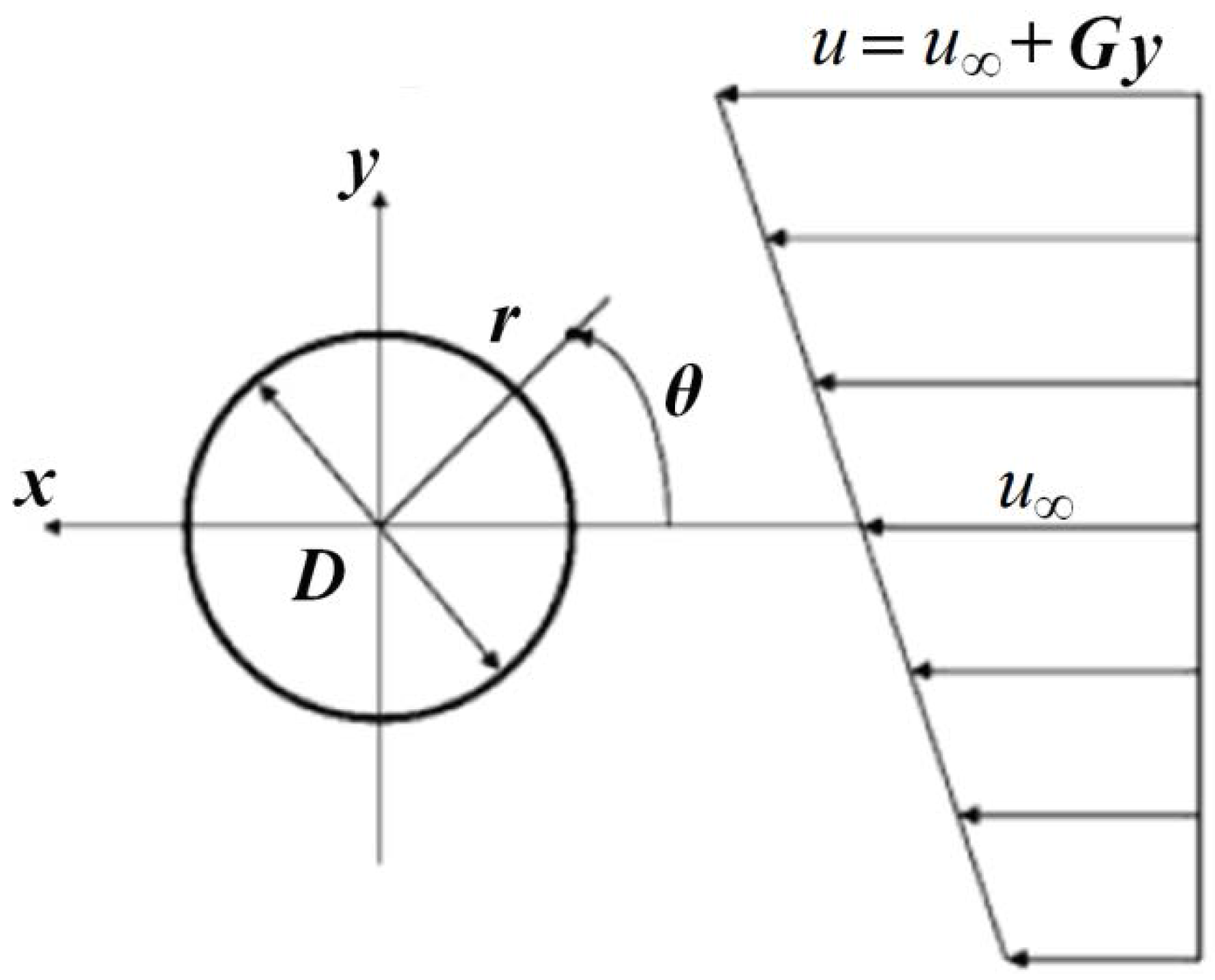
2. Governing Equations

A circular cylinder experiences time varying lift and drag, which are related to the vortex shedding, when placed in a flowing fluid. Thus, time varying vibration will occur when the cylinder is constrained to move on flexible supports, which is known as vortex-induced vibration (VIV). Moreover, the fluid around the cylinder is altered by this vibration, which affects the induced hydrodynamic forces in turn and the structure response is then changed. Therefore, this problem is associated with fully coupled fluid–structure interactions.
For control of VIV in an electrically low-conducting fluid, the actuators on the cylinder surface consists of two half cylinders mounted with alternating electrodes and magnets as shown in Figure 1. The momentum of the fluid round the cylinder surface is increased with the application of Lorentz force, which is directed parallel to the cylinder surface.
In this way, the electro-magnetic force F can be written in the dimensionless form:
F * = J × B ,
where the superscript “*” refers to the dimensional form, no superscript refers to the dimensionless form. This can be written in dimensionless form [36,38]
F * = N F ,
with
F r = 0 ,
F θ = e α ( r 1 ) g ( θ )   with   g ( θ ) = { 1 covered   with   actuator on   upper   surface 1   covered   with   actuator   on   lower   surface 0    elsewhere
where r and θ represent polar coordinates, r and θ denote the components in r and θ directions, respectively. α is a constant, denoting the effective depth of Lorentz force in the fluid. The interaction parameter is termed as N = j 0 B 0 a ρ u 2 , with the current density j 0 , B 0 the magnetic field, ρ the fluid density, and a the cylinder radius.
The exponential-polar coordinates system ( ξ , η ) is introduced here defined as r = e 2 π ξ , θ = 2 π η . Then, the stream function–vorticity equations in the dimensionless form, which express the flow considering an applied Lorentz force with the coordinate system attached on the moving cylinder, are termed as
H Ω t + ( U r Ω ) ξ + ( U θ Ω ) η = 2 Re ( 2 Ω ξ 2 + 2 Ω η 2 ) + N H 1 2 ( F θ ξ + 2 π F θ F r η ) ,
2 ψ ξ 2 + 2 ψ η 2 = H Ω ,
We need to mention that the above equations (Equations (2) and (3)) have the same forms as the equations in the absolute coordinate system. The stream function ψ is defined as ψ η = U r = H 1 2 u r , ψ ξ = U θ = H 1 2 u θ , while the vorticity Ω is Ω = 1 H ( U θ ξ U r η ) , with u r and u θ indicating the velocity components in r and θ directions, respectively. Moreover, H = 4 π 2 e 4 π ξ , Re = 2 u a ν , u is the free-stream velocity, ν is the kinematic viscosity, and the dimensionless time is t = t * u a .
The sketch of shear flow, which shows the change of the velocity in the cross-section plane of the cylinder, with a linear velocity profile u = u + G y [43] over a cylinder in two-dimensional domain is shown in Figure 2, where u is the free-stream velocity at the center-line θ = 0 , y is the coordinate in the lateral direction with y = 0 at the center of the cylinder, and G is the lateral velocity gradient.
Defining the shear rate K as K = 2 G a / u , a refers to the cylinder radius. Only the circumstance of a positive shear rate, i.e., K > 0 , needs to be discussed here, indicating that the flow velocity of the upper side prevails over that of the lower side.
Initially, the flow is regarded as inviscid. When the cylinder can only move in a cross flow direction, the initial flow field in the moving frame of reference can be described by
ψ = 2 s h ( 2 π ξ ) [ sin ( 2 π η ) + K 2 ( 2 c h ( 2 π ξ ) cos ( 4 π η ) e 2 π ξ ) ]   and   Ω = K
As for t > 0 , the cylinder is constrained to vibrate along the transverse direction with the effect of the vortex shedding. Based on the Galilean velocity decomposition and the stream function definition, we have
ψ = ψ + d l ( t ) d t e 2 π ξ cos ( 2 π η )
where the superscript “′” denotes the absolute coordinate (an inertial frame of reference), and no superscript denotes the coordinate (a non-inertial frame of reference) which is attached on the cylinder moving with the velocity d l ( t ) d t , where l is the cylinder displacement in the transverse direction.
The relative angle of the incoming flow direction is defined as θ 0 = tan 1 [ d l ( t ) d t ] , then
ψ = ψ + ( tan θ 0 ) e 2 π ξ cos ( 2 π η )
when ξ , e 2 π ξ 2 s h ( 2 π ξ ) , from Equation (5), we have
ψ = 2 s h ( 2 π ξ ) [ sin ( 2 π η θ 0 ) cos θ 0 + K 2 ( 2 c h ( 2 π ξ ) cos ( 4 π η ) 2 s h ( 2 π ξ ) ) ]
which depends on the shear rate K and the vibration of cylinder, and
Ω = K
On ξ = 0 , 1 H 2 ψ ξ 2 = 1 H 2 ψ ξ 2 tan θ 0 cos ( 2 π η )
1 H 2 ψ η 2 = 1 H 2 ψ η 2 + tan θ 0 cos ( 2 π η )
and Ω = 1 H ( 2 ψ ξ 2 + 2 ψ η 2 ) = 1 H ( 2 ψ ξ 2 + 2 ψ η 2 ) = Ω
Since ψ = 0 , so that
ψ = ( tan θ 0 ) cos ( 2 π η )   and   2 ψ η 2 = H tan θ 0 cos ( 2 π η )
where H = 4 π 2 . From Equation (7),
2 ψ η 2 = 0
Thus, one finally obtains
Ω = 1 H 2 ψ ξ 2
In addition, the applied Lorentz force has no relationship with the flow field, and involves two types which can be defined as the field Lorentz force F θ | ξ > 0 and the wall Lorentz force F θ | ξ = 0 . The field Lorentz force does not appear in any above equations, but acts as a source term affecting the boundary layer fluid and accordingly leads to the variations of hydrodynamic force. The wall Lorentz force, however, is independent of the flow field due to the non-slip boundary and affects directly on the surface of cylinder.

3. Hydrodynamic Forces

Defining the net hydrodynamic force F θ acting on a cylinder as
C F θ = F θ 1 2 ρ u 2 = ( C τ θ ) 2 + ( C p θ ) 2
If the prime coordinate system indicates the absolute coordinate (the inertial frame of reference) in the previous reference, the shear stress C τ θ is written as
C τ θ = τ r θ 1 2 ρ u 2 = 4 Re H 2 ψ ξ 2
As 2 ψ ξ 2 + 2 ψ η 2 = H Ω , then
C τ θ = 4 Re ( Ω + 1 H 2 ψ η 2 )
On the cylinder surface,
ψ = d l d t cos ( 2 π η )   and   Ω = Ω
Thus,
C τ θ = C τ F θ + C τ V θ
where C τ F θ = 4 Re Ω
C τ V θ = 4 Re d l d t cos ( 2 π η )
Therefore, the shear stress involves two components denoted as C τ F θ and C τ V θ , where C τ F θ is proportional to vorticity at the wall, whereas C τ V θ induced by the cylinder motion in viscous flow, has no relationship with the vorticity field.
The pressure C p θ is termed as based on the definition [41]
C p θ = F p θ 1 2 ρ u 2 = p θ p 1 2 ρ u 2 = P θ P
where the pressure is P = p ρ u 2 / 2 with p the pressure of the flow field. Then, C p θ can be formulated further by following mathematical derivation.
From the momentum equations in the moving coordinate of reference, one obtains
P θ P 0 = 4 Re 0 η Ω ξ d η + 4 π N 0 η F θ | ξ = 0 d η 4 d 2 l ( t ) d t 2 sin ( 2 π η )
and
P P 0 = 4 π 0 u r t e 2 π ξ d ξ 1 2 0 u θ u r η d ξ + 4 π 0 u θ 2 d ξ 4 Re 0 Ω η d ξ
Then,
C p θ = P θ P = C p F θ + C p W θ + C p V θ
where
C P F θ = 4 Re 0 η Ω ξ d η + C p 0
C p 0 = 1 + 4 π 0 u r t e 2 π ξ d ξ + 2 0 u θ u r η d ξ 4 π 0 u θ 2 d ξ + 4 Re 0 Ω η d ξ
C p W θ = 4 π N 0 η F θ | ξ = 0 d η
C p V θ = 4 d 2 l ( t ) d t 2 sin ( 2 π η )
Here, pressure C p θ consists of C p F θ induced by the field Lorentz force, C p W θ induced by the wall Lorentz force and C p V θ induced by the inertial force.
The hydrodynamic force is also regarded as a force consisting of drag force and lift force denoting the force components in the streamwise and the transverse directions, respectively. We have
C d θ = C p θ cos ( 2 π η ) + C τ θ sin ( 2 π η )
and
C l θ = C p θ sin ( 2 π η ) + C τ θ cos ( 2 π η )
where the subscripts “d” and “l” denote the drag and lift force, respectively.
The total force is attained by integrating the force distribution function along the cylinder surface, by defining the dimensionless form
C = F ρ u 2 a ,
Then, the drag C d can be termed as
C d = 0 2 π C d θ d θ = C d F + C d W
where
C d F = 2 Re 0 1 ( 2 π Ω Ω ξ ) sin ( 2 π η ) d η
C d W = 2 π N 0 1 F θ | ξ = 0 sin ( 2 π η ) d η
The lift C l is written as
C l = 0 2 π C l θ d θ = C l F + C l W + C l V
where
C l F = 2 Re 0 1 ( 2 π Ω Ω ξ ) cos ( 2 π η ) d η
C l W = 2 π N 0 1 F θ | ξ = 0 cos ( 2 π η ) d η
C l V = 4 π d 2 l d t 2 4 π Re d l d t
Hence,
C l = C l F + C l W 4 π d 2 l d t 2 4 π Re d l d t
where the first term on the right-hand side C l F , the so-called vortex-induced force, depends on the vorticity and the boundary vorticity flux on the surface of cylinder. The field Lorentz force N F θ | ξ > 0 serves as a source to influences the vorticity field, in turn, to alternate C l F . The second term, C l W , is induced by wall Lorentz force, which has no relationship with flow field. The third term, called inertial force, depends on acceleration of cylinder and the fourth term, called viscous damping force, depends on Reynolds number and cylinder velocity. Therefore, the second to fourth terms have no relationship with the varying flow field.

4. Cylinder Responses

As the cylinder is constrained to experience VIV in the transverse direction, the equation of motion in the absolute coordinate (the inertial frame of reference) may be termed as [42]
m d 2 l d t 2 + ς d l d t + m v i r ( ω n ω ) 2 ω 2 l = F l
where m is the dimensionless mass; ς is the dimensionless structure damping; m v i r is the virtual mass; and ω = 2 π f , f is vortex shedding frequency. When the lock-in occurs, the vortex shedding frequency is synchronized with the natural frequency of cylinder and f n / f remains invariant. Furthermore, F l is the hydrodynamic force in the transverse direction.
According to Equation (15),
F l = C l π = C l F π + C l W π 4 Re d l d t 4 d 2 l d t 2

5. Numerical Approach and Procedure for Fluid-Structure Coupling

The calculations are performed numerically. The detail process on numerical procedure of fluid–structure interaction is shown in Figure 3. At the beginning, based on the initial flow field described by Equation (4) and the boundary conditions Equations (5)–(8), the lift force exerted on the cylinder can be obtained at t > t 1 by Equation (15). Then, the displacement and velocity of cylinder can be obtained from the motion Equation (17). Subsequently, the flow field is advanced to the next time step by the integration of Equations (2) and (3) according to the boundary conditions calculated for update, as does the control process with Lorentz force at t > t 2 . Therefore, the flow field, the hydrodynamic force, the cylinder motion and so on can be obtained in the whole fluid–structure interactiion process with this method.
The exponential mapping in the radial direction allows us to work in a very large physical domain, so that we can avoid the well-known blockage effect (i.e., the effect of the size of apparatus or computational box). On the other hand, the grids near the cylinder are fine enough in a very small physical domain, so that the flow field can be described accurately. In the numerical calculations presented in this paper, the physical circular domain in polar coordinates is transformed into the rectangular ( ξ , η ) domain through the coordinate transformation ( r , θ ) ( ξ , η ) . The computations presented in this paper are run on a mesh consisting of N ξ × N η = 400 × 256 grid points.
The Alternative-Direction Implicit (ADI) algorithm was used to solve the equation of vorticity transport. A Fast Fourier Transform (FFT) algorithm was used to integrate the equation of stream function. Solving Equation (16) using the Runge–Kutta method allows calculating the cylinder motion. For more details on the numerical method and validation of the code, refer to [39,40,41,42]. The concrete procedure for simulating the coupling of fluid and structure is the same as [42]. Moreover, the above numerical methods have the accuracy of second order in space and first order in time [42]. The computational step sizes are Δ ξ = 0.004 and Δ η = 0.004 for all simulations appearing in the paper. The input parameters are as follows: density of fluid ρ = 1.0 × 10 3   kg / m 3 , kinematic viscosity ν = 1.0 × 10 6   m 2 / s , free-stream velocity u = 7.5 × 10 3   m / s , cylinder radius a = 1.0 × 10 2   m , (so that Re = 2 u a ν = 150 , where the flow about the cylinder is fully laminar), density of cylinder ρ c y l = 2.6 π × 10 3   kg / m 3 , and f = f n = 0.0675 / s (so that ρ c y l / ρ = 2.6 π ). For VIVs in dense fluid, the structural damping is so small that it is negligible [44]. In order to accentuate the effect of viscous damping force ( 4 Re d l d t ), it may even be assumed zero (i.e., ς = 0 ).

6. Results

From the previous derivations, the Lorentz force is parallel to the cylinder surface along the flow direction, which leads to the acceleration of the boundary layer fluid and improves the capacity of the fluid for overcoming the adverse pressure gradient. Therefore, the flow separation is suppressed, which change the induced fluid forces in turn and subsequently the cylinder response is altered. Moreover, the definition of interaction parameter N is indicated in Equation (1), which represents the strength of Lorentz force.

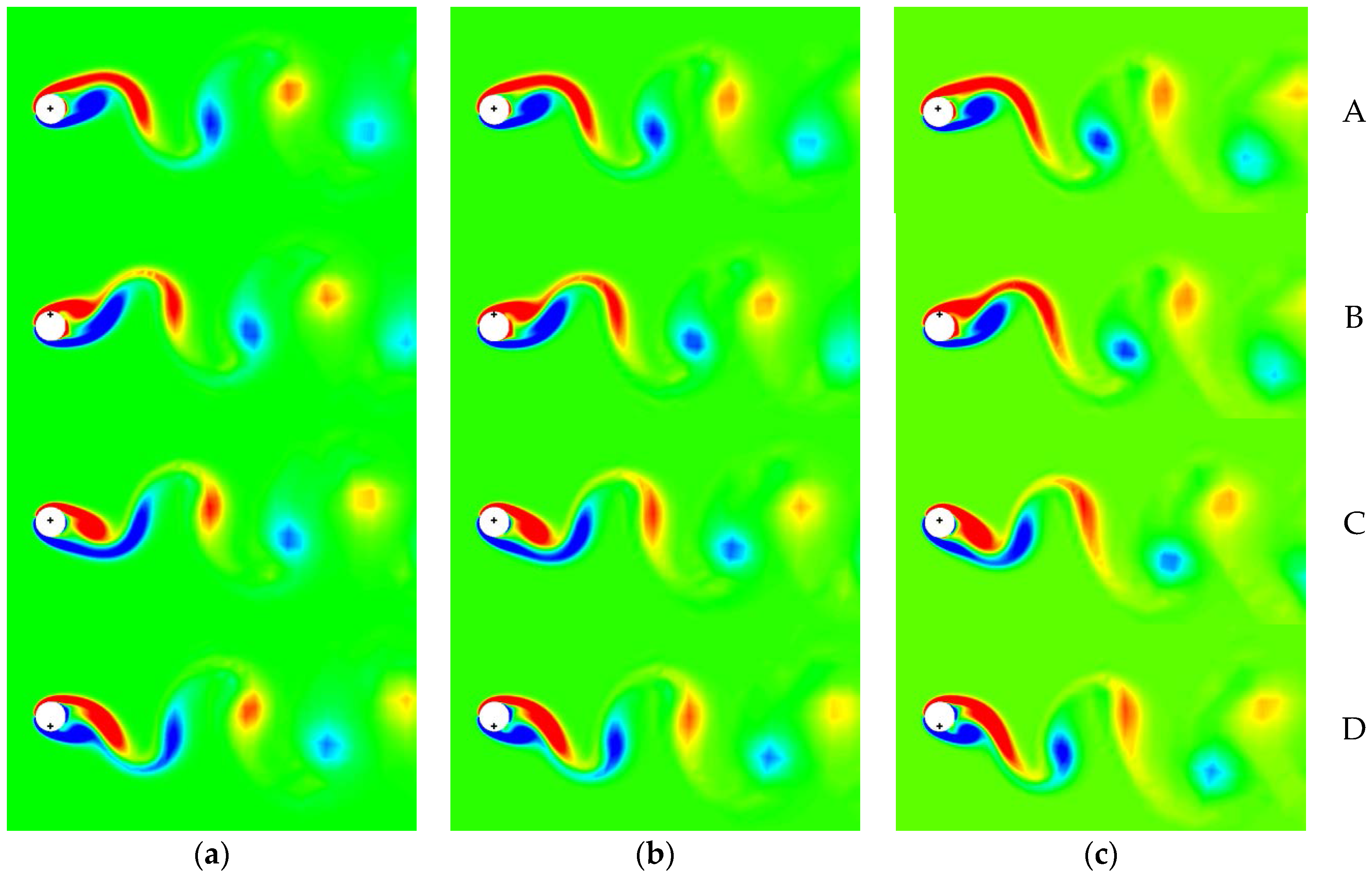
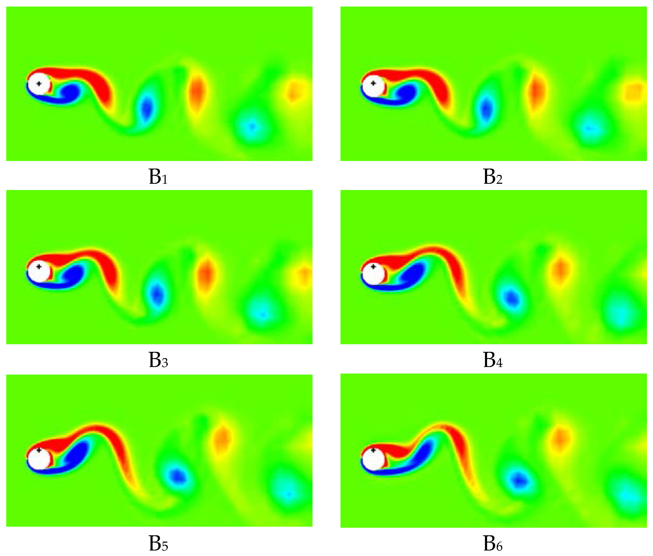
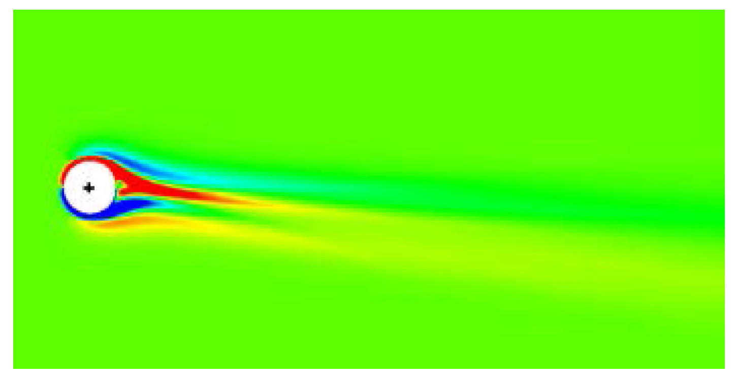
6.1. Control of VIV with Symmetrical Lorentz Force

In order to describe the differences between the VIV behavior of the cylinder in shear flow and that in uniform flow, the periodical variation of vortex-induced vibration for different shear rate K at the steady VIV with Re = 150 in a shedding cycle are exhibited in Figure 4 by the shaded vorticity contours, where the red refers to the negative vortex, and blue the positive. The cross-hairs mark the equilibrium position of cylinder for shear rate K = 0 . For convenience, the times at t = 0T/4, 1T/4, 2T/4 and 3T/4 in all the K cases are denoted by A, B, C and D, respectively, where T denotes one period of the cylinder oscillation.
The symmetrical flow field is broken due to the background vorticity, which is generated by shear flow that also causes the increase of upper vortex strength and the decrease of lower vortex strength. With the effect of shear flow, the separation point on the upper side of cylinder moves downstream due to the increase of fluid momentum on the upper side of cylinder while the separation point on the lower side of cylinder moves upstream due to the decrease of fluid momentum on the lower side of cylinder. The vortex street inclines toward the lower side and the inclination of vortex streets increase with the increasing shear rate K , as does the distance of two vortex rows. The equilibrium position of vibration cylinder shifts to the lower side due to the shear flow.
The variation of C d F ~ C l F phase diagram with shear rate K is shown in Figure 5. The curve moves down due to the shear flow, which means the lift points to the lower side of cylinder. Moreover, the absolute value of lift increases with the increase of shear rate, as do the amplitudes of drag and lift, which lead to the separation of points A and C.
The periodic variations of vorticity of VIV with K = 0.2 under the Lorentz force control with different values of interaction parameter N are exhibited in Figure 6 by the shaded vorticity contours, where the red represents the negative vortex, and blue the positive. The initial position of the cylinder is marked with cross-hairs. For convenience, the times at t = 0T/4, 1T/4, 2T/4 and 3T/4 in all the N cases are denoted by A, B, C and D, respectively, where T denotes one period of the cylinder oscillation. The interaction parameters are N = 0, 0.8 and 1.3 for the three columns in Figure 6. From the figure, the symmetry of flow field is broken as the background vorticity, which is generated by shear flow, increases the strength of upper vortex and decreases the strength of lower vortex. The vortex street slants toward the lower side due to the background vorticity, which is shown in the instance N = 0. It is obvious that the vortex shedding and the cylinder vibration are suppressed under the influence of symmetrical Lorentz force and the control effects increase with the increase of interaction parameter N. Despite the control, it is still observed that the front stagnation point moves to the upper side of cylinder and the wake shifts to the lower side, which generally occurs with the effect of shear incoming flow.
The distributions of shear stress C τ θ with different values of interaction parameter N for the different stages of one cycle are depicted in Figure 7, where the shear rate K = 0.2 . The symmetrical curve is broken due to the different strength of shear layers on the upper and lower sides, which is generated by shear flow. The boundary layer fluid is hastened by Lorentz force, leading to the increase of shear stress. In addition, the strength of shear stress increases with the increase of interaction parameter N . However, the shift of front stagnation point still exists and the shift amplitude of shear stress C τ θ decreases with the increase of Lorentz force (interaction parameter N ) on a cycle.
With the Lorentz force applied, the pressure on the surface of vibrating cylinder is composed of three parts
C p θ = P θ P = C p W θ + C p F θ + C p V θ
where C p W θ is the pressure induced by the wall Lorentz force, C p F θ is the pressure induced by vortex shedding and C p V θ is the pressure affected by the inertial force.
The effects of interaction parameter N on the distributions of C p W θ which has no relationship with flow field and cylinder vibration, are discussed firstly based on Figure 8 to examine the VIV control. The curve with positive values is symmetrical about the line θ = 180 ° . Therefore, the wall Lorentz force only causes the drag decrease, without the effect on the lift.
The distributions of C p F θ induced by vortex shedding at different stages of one cycle with different values of interaction parameter N are depicted in Figure 9 where the shear rate K = 0.2 , and A, B, C, and D correspond to those in Figure 6. As the stagnation point shifts to the upper side with the effect of shear flow, the pressure distribution shifts along the clockwise direction as well, which then leads to the increase and decrease of pressure on the upper and lower side, respectively. Obviously, these basic features of VIV in shear flow maintains for the small symmetrical Lorentz force. The pressure on the leeward decreases rapidly with the effect of Lorentz force, leading to the increase of drag and the decrease of the lift oscillating amplitude, in turn, as well as the decline of cylinder vibration. However, the curves are asymmetrical about θ = 180 ° due to the shear flow even if Lorentz force is large enough.
The inertial force C p V θ , resulting from the acceleration of the cylinder, has influence on the pressure distributions as well. The distributions of C p V θ related with the inertial force for different values of interaction parameter N are depicted in Figure 10. When N = 0 , the additional lift generated by the background vortex caused by the shear incoming flow leads to the acceleration d 2 l ( t ) d t 2 at Time B being larger than that at Time D. Namely, the inertial force at Time B is larger than that at Time D. When N > 0 , the inertial force decreases with the increase of the values of Lorentz force while the inertial force at Time B is still larger than that at Time D.
The lift–drag phase diagrams with different values of interaction parameter N for shear rate K = 0.2 are depicted in Figure 11. The lift–drag curve shrinks with the increase of the values of Lorentz force, which indicates the decrease of drag and lift vibration. Therefore, the amplitude of vibrating cylinder decreases. Moreover, the lift–drag curve (a Figure 8 shape at N = 0) is switched to a teardrop shape by increasing the interaction parameter N. For N = 0, the drag at Time C is larger than that at Time A due to the fact that the strength of upper vortex is larger than that of lower vortex with the effect of shear flow (shown in Figure 6) and then the pressure C p F θ on the cylinder leeward at Time C is smaller than that at Time A (shown in Figure 9), which leads to Point A and Point C separating in the lift–drag phase diagram. The flow field on the cylinder leeward is gradually dominated by the upper vortex with the increase of Lorentz force. At Time C, the shear layer of upper side is accelerated under the effect of pressure side which leads to the increase of the strength of upper vortex, then the decrease of pressure C p F θ on the cylinder leeward and subsequently the increase of drag. The distance between Point A and Point C of lift–drag curve is increased, which leads to the lift–drag phase diagram switching to a teardrop shape gradually. Furthermore, the curve shifts from the left to the right, which implicates the increase of drag. The additional lift still exists under the effect of shear flow.
The evolution of the cylinder displacement from still to steady vibration, then to a new steady state with symmetric Lorentz force ( N = 0.8 ) for K = 0.2 is shown in Figure 12. The release of transverse confinement occurs at t = 446 , which leads to the displacement of cylinder increasing gradually under the effect of lift. Moreover, the equilibrium position which separates from the point l / a = 0 and shifts to the lower side. When t = 640 , the steady vibration is reached. When the symmetric Lorentz force is initiated at time t 2 = 650 , a well-developed VIV is performed, and the cylinder displacement will decrease over time. However, the equilibrium position shifts because shear flow still exists.
The variation of vorticity of VIV before and after the application of symmetric Lorentz force ( N = 0.8 ) for K = 0.2 is shown in Figure 13 where time B i in this figure corresponds to that in Figure 12 while the cylinder arrives at the lowermost position. The cylinder starts to vibrate with the effect of lift as the confinement of cylinder is released. With the energy transferring from the fluid to the cylinder, there is an increase in the cylinder oscillations. The corresponding vortex patterns are described as B 1 ~ B 4 . The cylinder vibrates steadily as the total cylinder energy develops into an equilibrium state. The corresponding vortex pattern is described as B 5 . When the symmetric Lorentz force is attached on the cylinder at time t 2 = 650 , the cylinder vibration and the fluid separation are suppressed at some extent ( B 6 ~ B 8 ) while the wake vortex is inclined to the lower side.
Time evolutions of lift–drag phase diagram for VIV in a developing and then suppressed process with N = 0.8 and K = 0.2 are shown in Figure 14. The closed curve A 1 B 1 C 1 D 1 A 1 , which represents the stationary cylinder, is turned right at 180° as the cylinder starts to vibrate. Then, Point A and Point C are separated until VIV is well-established. However, Point A and Point C do not coincide any longer, where the phase diagram C d F ~ C l F is depicted by the closed-curve A 5 B 5 C 5 D 5 A 5 . The drag C d F that is generated by the field Lorentz force increases with the application of symmetric Lorentz, though the total drag C d decreases with the wall Lorentz force effect [41]. The phase diagram therefore shifts to the right significantly. Due to the suppression of flow separation under the effect of symmetric Lorentz force, the vibration of lift/drag decays and the curve shrinks, which then leads to the decrease of the displacement oscillation. Finally, the cylinder vibrates steadily with small amplitude (Figure 14, curve A 8 B 8 C 8 D 8 A 8 ).
The vibration amplitude varies significantly with the interaction parameter N , as depicted in Figure 15. Notably, the amplitude of cylinder vibration decreases with the increase of N, and the cylinder will finally rest when the interaction parameter N is large enough.

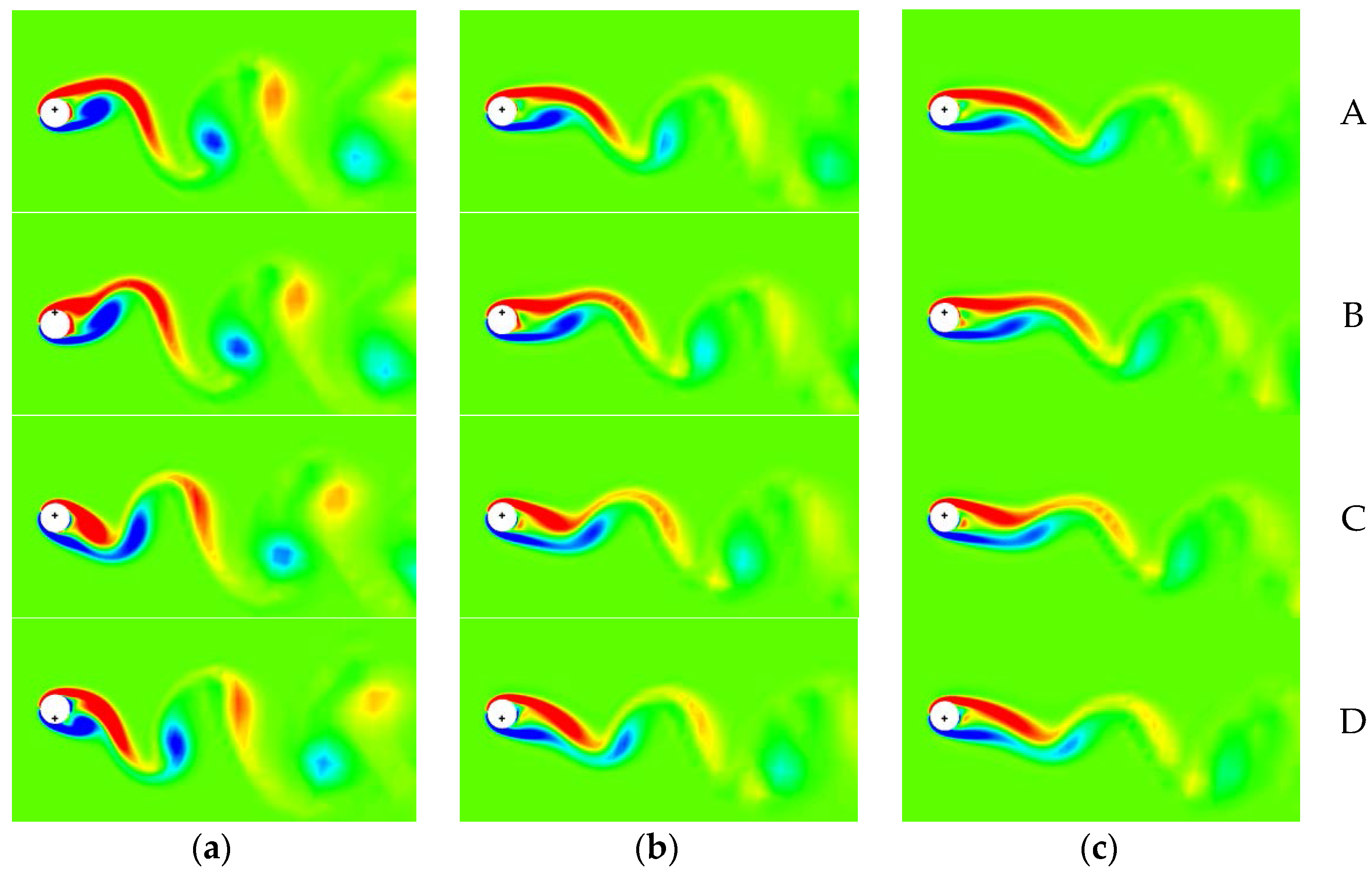
6.2. Control of VIV with Asymmetrical Lorentz Force

For a shear flow past a cylinder, the shift of front stagnation point and additional lift, pointing to lower side for K > 0 , are induced under the effect of background vorticity, even if symmetrical Lorentz forces are applied. Therefore, the equilibrium position of cylinder controlled by symmetrical Lorentz forces departs from its initial position, as mentioned in Figure 12. However, the lift C l L generated by asymmetrical Lorentz forces can be used to counteract the additional lift, so that the total lift C l = 0 and then the cylinder shifts to the initial position.
The evolution of the cylinder displacement before and after the application of asymmetric Lorentz force (upper surface N = 3 , lower surface N = 2 ) in a shear flow with K = 0.2 is shown in Figure 16. When the asymmetric Lorentz force is initiated at time t 2 = 650 when the VIV is well-developed, the lift C l L pointing to the upper side is generated, which can counteract the additional lift to suppress the vibration of cylinder and lead to the equilibrium position of cylinder shifting back to the upper side. Finally, the cylinder is steady on the initial position.
The vorticity of VIV with the asymmetric Lorentz force is shown in Figure 17. The wake suppressed completely by the Lorentz force inclines to the lower side with the influence of shear flow.
The distribution of shear stress C τ θ on the surface of cylinder with the asymmetric Lorentz force is depicted in Figure 18. Due to the higher flow speed on the upper surface, the shear stress on the upper side prevails over that on the lower side obviously.
The distribution of pressure coefficient C p W θ with the asymmetric Lorentz force is shown in Figure 19. The value of C p W θ is positive and the maximum is achieved at θ = 180 ° . Meanwhile, the C p W θ on the lower side is larger than that on the upper side. Thus, the wall Lorentz force results in the amplification of lift with the direction pointing to the upper side and the drag reduction (thrust generated).
The distribution of C p F θ on the surface of cylinder with the asymmetric Lorentz force is depicted in Figure 20. With the effect of asymmetric Lorentz force, the curve moves down. The pressure on the upper surface prevails over that on the lower surface, while the decrease of pressure on the leeward side is sharper than that on the windward side. Therefore, the lift decreases and the drag increases with the effect of field Lorentz force, which is opposite with the effect of wall Lorentz force. However, the total effect is dominated by the wall Lorentz force.

7. Conclusions

With exponential-polar coordinates attached on a moving cylinder, we have deduced the related equations considering the electro-magnetic force for the shear flow, i.e., the stream function–vorticity equations, the initial and boundary conditions, the hydrodynamic forces on the cylinder surface, and the cylinder motion equation together with the mathematical expressions of the lift force C l . The applied Lorentz force was not dependent on the flow field and it involves two categories: the field Lorentz force F θ | ξ > 0 and the wall Lorentz force F θ | ξ = 0 . As a source term, the field Lorentz force affected the flow field in the boundary layer, which leads to the variations of hydrodynamic force. The wall Lorentz force, however, is independent of the flow field due to the non-slip boundary and affects directly on the surface of cylinder.
The momentum of the fluid round the cylinder surface is increased by Lorentz force, which overcomes the effect of the “adverse” pressure gradient. Therefore, the separation points move downstream, and even disappear on the cylinder surface. With the application of symmetrical Lorentz forces, the symmetric field Lorentz force can increase the drag, suppress the flow separation, decay the lift fluctuation, and, in turn, suppress the VIV, whereas the wall Lorentz force decreases the drag only, i.e. no effect on the lift. With the application of asymmetrical Lorentz forces besides above-mentioned effects, the field Lorentz force can strengthen additional lift (negative value) induced by shear flow, whereas the wall Lorentz force can counteract the additional lift, which dominates the total effect. Therefore, it is notable that the asymmetrical Lorentz force, which suppresses the lift vibration and enhances the lift value, can be applied to overcome the lift loss that is caused by the shear flow.
From the above discussion, the aims for the vibration suppression, drag reduction and lift amplification have been obtained with application of Lorentz force. More complicated geometries, such as wing sections, can be controlled with application of this approach. The optimum performance can be obtained with changing the position of actuators in the applications based on the separation points, vortexes, the suction and pressure sides and so on. In addition, the value of Lorentz force varies with time according to the instantaneous flow field, which can be applied to control varying flow conditions, such as dynamically-changing angles of attack.

Acknowledgments

The work was supported by the National Natural Science Foundation of China (Grant Nos. 11672135 and 11202102), the Fundamental Research Funds for the Central Universities (Grant No. 30916011347) and A Foundation for the Author of National Excellent Doctoral Dissertation of PR China (Grant No. 201461).

Author Contributions

Hui Zhang conceived the study, wrote the paper and interpreted the results. Meng-ke Liu participated in data analysis and editing the manuscript. Bao-chun Fan and Zhi-hua Chen reviewed the study plan and corrected the grammar mistakes. Jian Li and Ming-yue Gui helped in the simulation.

Conflicts of Interest

The authors declare no conflict of interest.

References

  1. Cachafeiro, H.; de Arevalo, L.F.; Vinuesa, R.; Lopez-Vizcaino, R.; Luna, M. Analysis of vacuum evolution inside Solar Receiver Tubes. Energy Procedia 2015, 69, 289–298. [Google Scholar] [CrossRef]
  2. Vinuesa, R.; de Arevalo, L.F.; Luna, M.; Cachafeiro, H. Simulations and experiments of heat loss from a parabolic trough absorber tube over a range of pressures and gas compositions in the vacuum chamber. J. Renew. Sustain. Energy 2016, 8, 023701. [Google Scholar] [CrossRef]
  3. Feng, C.C. The Measurement of Vortex-Induced Effects in Flow Past Stationary and Oscillating Circular and D-Section Cylinders; University of British Columbia: Vancouver, BC, Canada, 1968. [Google Scholar]
  4. Griffin, O.M.; Koopmann, G.H. The vortex-exited lift and reaction forces on resonantly vibrating cylinders. J. Sound Vib. 1977, 54, 435–448. [Google Scholar] [CrossRef]
  5. Griffin, O.M. Vortex-excited cross-flow vibrations of a single cylindrical tube. J. Press. Vessel Technol. 1980, 102, 158–166. [Google Scholar] [CrossRef]
  6. Griffin, O.M.; Ramberg, S.E. Some recent studies of vortex shedding with application to marine tubulars and risers. Eur. J. Mech. B Fluids 1993, 250, 481–508. [Google Scholar] [CrossRef]
  7. Brika, D.; Laneville, A. Vortex-induced vibration of a long flexible circular cylinder. ASME J. Energy Res. Technol. 1982, 104, 2–13. [Google Scholar] [CrossRef]
  8. Hover, F.S.; Miller, S.N.; Triantafyllou, M.S. Vortex-induced vibration of marine cables: Experiments using force feedback. J. Fluids Struct. 2011, 27, 354–366. [Google Scholar] [CrossRef]
  9. Gharib, M.R. Vortex-Induced Vibration, Absence of Lock-in and Fluid Force Deduction; California Institute of Technology: Pasadena, CA, USA, 1999. [Google Scholar]
  10. Khalak, A.; Williamson, C.H.K. Fluid forces and dynamics of a hydroelastic structure with very low mass and damping. J. Fluids Struct. 1997, 11, 973–982. [Google Scholar] [CrossRef]
  11. Slaouti, A.; Stansby, P.K. Forced Oscillation and Dynamics Response of a Cylinder in a Current Investigation by the Vortex Method. In Proceedings of the BOSS ’94 Conference, Cambridge, MA, USA, 12–15 July 1994; pp. 645–654.
  12. Zhou, C.Y.; So, R.M.C.; Lam, K. Vortex-induced vibrations of an elastic circular cylinder. J. Fluids Struct. 1999, 13, 165–189. [Google Scholar] [CrossRef]
  13. Shiels, D.; Leonard, A.; Roshko, A. Flow-induced vibration of a circular cylinder at limiting structural parameters. J. Fluid Mech. 2001, 15, 3–21. [Google Scholar] [CrossRef]
  14. Leonard, A.; Roshko, A. Aspect of flow-induced vibration. J. Fluids Struct. 2001, 15, 415–425. [Google Scholar] [CrossRef]
  15. Williamson, C.H.K.; Govardhan, R. Vortex-induced vibrations. Annu. Rev. Fluid Mech. 2004, 36, 413–455. [Google Scholar] [CrossRef]
  16. Morse, T.L.; Williamson, C.H.K. Prediction of vortex-induced vibration response by employing controlled motion. J. Fluid Mech. 2009, 634, 5–39. [Google Scholar] [CrossRef]
  17. Franzini, G.R.; Fujiarra, A.L.C.; Meneghini, J.R.; Korkischko, I.; Franciss, R. Experimental investigation of Vortex-Induced Vibration on rigid, smooth and inclined cylinders. J. Fluids Struct. 2009, 25, 742–750. [Google Scholar] [CrossRef]
  18. Lam, K.; Zou, L. Three-dimensional numerical simulation of cross-flow around four cylinders in an in-line square configuration. J. Fluids Struct. 2010, 26, 482–502. [Google Scholar] [CrossRef]
  19. Trim, A.D.; Braaten, H.; Lie, H.; Tognarelli, M.A. Experimental investigation of vortex-induced vibration of long marine risers. J. Fluids Struct. 2005, 21, 335–361. [Google Scholar] [CrossRef]
  20. Yeung, R.W. Fluid dynamics of finned bodies—From VIV to FPSO. In Proceedings of the 12th International Offshore and Polar Engineering Conference, Kitakyushu, Japan, 26–31 May 2002.
  21. Bearman, P.W.; Brankovic, M. Experimental studies of passive control of vortex-induced vibration. Eur. J. Mech. B Fluids 2004, 23, 9–15. [Google Scholar] [CrossRef]
  22. Allen, D.W.; Henning, D.L. Comparison of Various Fairing Geometries for Vortex Suppression at High Reynolds Numbers. In Proceedings of the Offshore Technology Conference, Houston, TX, USA, 5–8 May 2008.
  23. Assi, G.R.S.; Bearman, P.W.; Kitney, N. Low drag solutions for suppressing vortex-induced vibration of circular cylinders. J. Fluids Struct. 2009, 25, 666–675. [Google Scholar] [CrossRef]
  24. Galvao, R.; Lee, E.; Farrell, D.; Hover, F.; Triantafyllou, M.; Kitney, N.; Beynet, P. Flow control in flow–structure interaction. J. Fluids Struct. 2008, 24, 1216–1226. [Google Scholar] [CrossRef]
  25. Modi, V.J. Moving surface boundary-layer control: A review. J. Fluids Struct. 1997, 33, 229–242. [Google Scholar] [CrossRef]
  26. Munshi, S.R.; Modi, V.J.; Yokomizo, T. Aerodynamics and dynamics of rectangular prisms with momentum injection. J. Fluids Struct. 1997, 11, 873–892. [Google Scholar] [CrossRef]
  27. Korkischko, I.; Meneghini, J.R. Suppression of vortex-induced vibration using moving surface boundary-layer control. J. Fluids Struct. 2012, 34, 259–270. [Google Scholar] [CrossRef]
  28. Wu, C.J.; Wang, L.; Wu, J.Z. Suppression of the von Karman vortex street behind a circular cylinder by a traveling wave generated by a flexible surface. J. Fluid Mech. 2007, 574, 365–391. [Google Scholar] [CrossRef]
  29. Tchieu, A.A.; Leonard, A. Experimental investigation on the suppression of vortex-induced vibration of long flexible riser by multiple control rods. J. Fluids Struct. 2012, 30, 115–132. [Google Scholar]
  30. Gbadebo, S.A.; Cumpsty, N.A.; Hynes, T.P. Control of three-dimensional separations in axial compressors by tailored boundary layer suction. J. Turbomach. 2008, 130, 011004. [Google Scholar] [CrossRef]
  31. Chng, T.L.; Rachman, A.; Tsai, H.M.; Zha, G.C. Flow control of an airfoil via injection and suction. J. Aircr. 2009, 46, 291–300. [Google Scholar] [CrossRef]
  32. Arcas, D.; Redekopp, L. Aspects of wake vortex control through base blowing/suction. Phys. Fluids 2004, 16, 452–456. [Google Scholar] [CrossRef]
  33. Fransson, J.H.M.; Konieczny, P.; Alfredsson, P.H. Flow around a porous cylinder subject to continuous suction or blowing. J. Fluids Struct. 2004, 19, 1031–1048. [Google Scholar] [CrossRef]
  34. Patil, S.K.R.; Ng, T.T. Control of separation using span wise periodic porosity. AIAA J. 2010, 48, 174–187. [Google Scholar] [CrossRef]
  35. Crawford, C.H.; Karniadakis, G.E. Control of External Flows via Electro-Magnetic Fields. In Proceedings of the AIAA Fluid Dynamics Conference, San Diego, CA, USA, 19–22 June 1995.
  36. Weier, T.; Gerbeth, G.; Mutschke, G.; Platacis, E.; Lielausis, O. Experiments on cylinder wake stabilization in an electrolyte solution by means of electromagnetic forces localized on the cylinder surface. Exp. Therm. Fluid Sci. 1998, 16, 84–91. [Google Scholar] [CrossRef]
  37. Kim, S.; Lee, C.M. Control of flows around a circular cylinder: Suppression of oscillatory lift force. Fluid Dyn. Res. 2001, 29, 47–63. [Google Scholar] [CrossRef]
  38. Posdziech, O.; Grundmann, R. Electromagnetic control of seawater flow around circular cylinders. Eur. J. Mech. B Fluids 2001, 20, 255–274. [Google Scholar] [CrossRef]
  39. Zhang, H.; Fan, B.C.; Chen, Z.H. Computations of optimal cylinder flow control in weakly conductive fluids. Comput. Fluids 2010, 39, 1261–1266. [Google Scholar] [CrossRef]
  40. Zhang, H.; Fan, B.C.; Chen, Z.H. Optimal control of cylinder wake by electromagnetic force based on the adjoint flow field. Eur. J. Mech. B Fluids 2010, 29, 53–60. [Google Scholar] [CrossRef]
  41. Zhang, H.; Fan, B.C.; Chen, Z.H.; Li, Y.L. Effect of the Lorentz force on cylinder drag reduction and its optimal location. Fluid Dyn. Res. 2011, 43, 015506. [Google Scholar] [CrossRef]
  42. Zhang, H.; Fan, B.C.; Chen, Z.H.; Li, H.Z. An in-depth study on vortex-induced vibration of a circular cylinder with shear flow. Comput. Fluids 2014, 100, 30–44. [Google Scholar] [CrossRef]
  43. Lei, C.; Cheng, L.; Kavanagh, K. A finite difference solution of the shear flow over a circular cylinder. Ocean Eng. 2000, 27, 271–290. [Google Scholar] [CrossRef]
  44. Sarpkaya, T. A critical review of the intrinsic nature of vortex-induced vibrations. J. Fluids Struct. 2004, 19, 389–447. [Google Scholar] [CrossRef]
Figure 1. Lorentz force on the cylinder surface.
Applsci 07 00061 g001
Figure 2. Sketch of shear flow over circular cylinder.
Applsci 07 00061 g002
Figure 3. The detailed process of the numerical procedure of fluid–structure interaction.
Applsci 07 00061 g003
Figure 4. The periodical variation of flow field with different shear rate K where A, B, C and D represent the times at t = 0T/4, 1T/4, 2T/4 and 3T/4, respectively: (a) K = 0 ; (b) K = 0.1 ; and (c) K = 0.2 .
Applsci 07 00061 g004
Figure 5. The variation of C d F ~ C l F phase diagram with shear rate K .
Applsci 07 00061 g005
Figure 6. Vorticity evolutions of VIV with different values of interaction parameter N for shear rate K = 0.2 where A, B, C and D represent the times at t = 0T/4, 1T/4, 2T/4 and 3T/4, respectively: (a) N = 0; (b) N = 0.8; and (c) N = 1.3.
Applsci 07 00061 g006
Figure 7. Distributions of shear stress C τ θ on the surface of cylinder with different values of interaction parameter N for shear rate K = 0.2 : (a) Time A; (b) Time B; (c) Time C; and (d) Time D.
Applsci 07 00061 g007aApplsci 07 00061 g007b
Figure 8. Distributions of pressure coefficient C p W θ with Lorentz force controls.
Applsci 07 00061 g008
Figure 9. Distribution of C p F θ on the surface of cylinder with different values of interaction parameter N for shear rate K = 0.2 : (a) Time A; (b) Time B; (c) Time C; and (d) Time D.
Applsci 07 00061 g009
Figure 10. Distributions of C p V θ on cylinder surface with K = 0.2 for different values of interaction parameter N .
Applsci 07 00061 g010
Figure 11. Lift–drag phase diagrams with different values of interaction parameter N for shear rate K = 0.2 .
Applsci 07 00061 g011
Figure 12. Evolution of the cylinder displacement with the symmetric Lorentz force ( N = 0.8 ) for K = 0.2 .
Applsci 07 00061 g012
Figure 13. (B1B8) Instantaneous vortex patterns of VIV before and after the application of symmetric Lorentz force ( N = 0.8 ) for K = 0.2 .
Applsci 07 00061 g013aApplsci 07 00061 g013b
Figure 14. Time evolutions of lift C l F and drag C d F for VIV development and suppression with the symmetric Lorentz force ( N = 0.8 ) for K = 0.2 .
Applsci 07 00061 g014
Figure 15. Limiting amplitude of oscillating cylinder displacement after control versus the interaction parameter N for K = 0.2 .
Applsci 07 00061 g015
Figure 16. Evolution of the cylinder displacement before and after application of Lorentz force (upper surface N = 3 , lower surface N = 2 ) in shear flow for K = 0.2 .
Applsci 07 00061 g016
Figure 17. The vorticity of VIV with the Lorentz force (upper surface N = 3 , lower surface N = 2 ) for K = 0.2 .
Applsci 07 00061 g017
Figure 18. The distribution of shear stress C τ θ on the cylinder surface with the asymmetric Lorentz force (upper surface N = 3 , lower surface N = 2 ) for shear rate K = 0.2 .
Applsci 07 00061 g018
Figure 19. The distributions of pressure coefficient C p W θ with the asymmetric Lorentz force (upper surface N = 3 , lower surface N = 2 ) for shear rate K = 0.2 .
Applsci 07 00061 g019
Figure 20. The distribution of pressure induced by vortex C p F θ on the surface of cylinder with the asymmetric Lorentz force (upper surface N = 3 , lower surface N = 2 ) for shear rate K = 0.2 .
Applsci 07 00061 g020

