Article

High Electrocatalytic Performance of CuCoNi@CNTs Modified Glassy Carbon Electrode towards Methanol Oxidation in Alkaline Medium

by
Amina A. Hamza
1,
Sayed M. El-Refaei
2,
Ahmed A. Elzatahry
1,* and
Aboubakr M. Abdullah
3,*
1
Materials Science and Technology Program, College of Arts and Science, Qatar University, Doha 2713, Qatar
2
Chemistry Department, Faculty of Science, Cairo University, Giza 12613, Egypt
3
Center for Advanced Materials, Qatar University, Doha 2713, Qatar
*
Authors to whom correspondence should be addressed.
Appl. Sci. 2017, 7(1), 64; https://doi.org/10.3390/app7010064
Submission received: 4 November 2016 / Revised: 26 December 2016 / Accepted: 4 January 2017 / Published: 10 January 2017

Abstract

:
A novel non-precious multiwalled carbon nanotubes (CNTs)—supported metal oxide electrocatalyst was developed for methanol electrooxidation in alkaline medium. The catalyst was fabricated by simultaneous electrodeposition of copper-cobalt-nickel ternary nanostructures (CuCoNi) on a glassy carbon electrode (GCE) modified with CNTs. The proposed electrode was characterized using X-ray diffraction (XRD), energy dispersive X-ray (EDX), and scanning electron microscopy (SEM). The electrochemical behavior and the electrocatalytic performance of the suggested electrode towards the oxidation of methanol were evaluated by cyclic voltammetry (CV), linear sweep voltammetry (LSV), and chronoamperometry (CA) in alkaline medium. Several parameters were investigated, e.g., deposition time, potential scan rate, etc. Compared to Cu, Co, or Ni mono electrocatalysts, the electrode based on ternary-metals exhibited superior electrocatalytic activity and stability towards methanol electrooxidation. For instance, CuCoNi@CNTs/GCE has shown at least 2.5 times electrocatalytic activity and stability compared to the mono eletrocatalysts. Moreover, the present study found that the optimized loading level is 1500 s of simultaneous electrodeposition. At this loading level, it was found that the relation between the Ip1/2 function and scan rate gives the characteristic features of a catalytic process. The enhanced activity and stability of CuCoNi@CNTs/GCE was attributed to (i) a synergism between three metal oxides coexisting in the same structure; (ii) the presence of CNTs as a support for the metal oxides, that offers high surface area for the deposited tertiary alloy and suppresses the aggregation and sintering of the metals oxide with time; as well as (iii) the increase of the conductivity of the deposited semiconducting metal oxides.

1. Introduction

Owing to the world energy crisis and fossil fuels depletion, the development of renewable alternative energy sources and technologies such as fuel cells (FCs), solar cells, and wind energy are presently being researched throughout the world [1]. FCs have received much attention recently due to their great range of benefits, for example high efficiencies, low emission, and fuel flexibility [2,3,4]. The most famous FC is the H2-O2 system, however using H2 as a fuel has many drawbacks related to its explosive and flammable nature, so it is neither easy to transport nor store [2,3,4]. As a result, there are many other organic molecules that have been proposed to replace H2 in the FCs such as methanol, ethanol, and glucose [2,3,4]. Methanol as a fuel has many advantages over H2 such as low-cost, availability, ease of storage, and transport. Therefore, direct methanol fuel cells (DMFCs) are considered as one of the best choices for future clean energy sources [5,6]. The electrooxidation of methanol is considered the key step in DMFCs in both alkaline and acidic fuel cells, and the commercialization of DMFCs is limited in part by the durability, scarcity, and high cost of the Pt-based methanol electrooxidation catalysts [5,6].
Pt and Pt-based materials are the most famous catalysts for methanol electro-catalytic oxidation in the DMFCs, especially in the low temperature FCs (both alkaline and acidic) [6,7]. However, the formation of poisoning intermediates that are adsorbed strongly on the catalyst surface (e.g., COad and other carbonaceous materials), which are generally produced during the methanol oxidation process, can in the long run hamper the electrooxidation reaction and deteriorate the electrocatalytic activity of the catalyst, which finally results in a severe failure of FCs as a whole [6,7].
Recently, researchers’ attention has been devoted to non-Pt based transition metal oxide catalysts for methanol oxidation in alkaline medium such as NiOx, CoOx, CuOx, AgOx and FeOx, which are characterized by good electrocatalytic activity, stability, and low poisoning ability in alkaline medium [8,9,10,11,12,13,14]. Among the aforementioned materials, NiOx [8], CuOx [10], and CoOx [11] have been considered the most prominent electrocatalysts for methanol oxidation in alkaline medium. NiOx has shown high electrocatalytic activity towards alcohol oxidation in alkaline medium and this high activity is attributed to the unpaired ‘d’ electrons and vacant d-orbitals associated with the oxidized form of nickel oxy-hydroxide (NiOOH), which has been extensively engaged in many electrocatalytic processes [15]. On the other hand, CuOx, with different fabrication methods and morphologies, has shown very good results towards methanol and glucose oxidation in alkaline medium [10,16,17]. In addition, alloying CuOx with NiOx demonstrated a synergistic effect towards methanol oxidation that was attributed to the suppression of the γ-NiOOH phase formation along with the stabilization of the β-NiOOH phase, of which the latter is the active phase in alcohol oxidation processes in alkaline medium [18]. Furthermore, CoOx alone is not considered as a good electrocatalyst, but it has shown good electrocatalytic activity and stability for alcohol oxidation when it is alloyed with NiOx [19]. For these reasons the tertiary alloy of CuCoNiOx is expected to exhibit high electrocatalytic activity and stability towards methanol oxidation in the alkaline DMFCs. In this context, there is only one article published recently that reports the synergistic effect between the three metal oxides if they are present in the same alloy towards methanol oxidation in alkaline medium [20]. According to this report, CuCoNi (copper-cobalt-nickel ternary nanostructures) modified graphite electrode G/NiCuCo has shown better electrocatalytic activity towards methanol oxidation in comparison to G/Cu, G/Ni, G/Co, G/CuCo, G/NiCo, and G/CuNi [20].
In the last decade, the replacement of old carbon support materials in the FCs, such as carbon black, with alternative high surface area carbon materials became an important issue of research [21,22]. In this regard, CNTs (carbon nanotubes) that exhibit a unique structure of one-dimensional multiwalled tubes composed of sp2-bonded carbon atoms, with an enormous capacity to conduct electricity and large specific surface area, are considered a suitable support for loading metal oxide nanoparticles, which increases the dispersion and prevents aggregation and sintering of deposited metal oxide particles, and improves both the stability and catalytic activity of the deposited metal oxide nanoparticles [21,22]. As a result, blending the CNTs with metal oxides is a good way to enhance the catalytic activity and stability of the proposed electrode [21,22].
The purpose of the present work is to fabricate a ternary catalyst composed of NiOx, CuOx, and CoOx modified CNTs/GCE (glassy carbon electrode) and determine their electrocatalytic activity towards methanol oxidation in alkaline medium at different deposition times. The material characterization of the proposed electrodes was done using X-ray diffraction (XRD), energy dispersive X-ray (EDX), and scanning electron microscopy (SEM). Cyclic voltammetry (CV), linear sweep voltammetry (LSV) and chronoamperometry (CA) were used for the electrochemical characterizations and activity testing.

2. Materials and Methods

All chemicals used in this work were of analytical grade and were purchased from Merck (Kenilworth, NJ, USA), Sigma Aldrich (Schnelldorf, Germany) and they were used as received without any further purification. All solutions were prepared using doubled-distilled water.

2.1. Measurements

An electrochemical cell with a three-electrode configuration was used in this study. A graphite rod, saturated calomel electrode (SCE), and glassy carbon electrode (GCE) (GAMRY Instrument Company, A = 0.071 cm2, Warminster, PA, USA) were used as counter, reference, and working electrodes, respectively. All potentials will be presented with respect to SCE. The GCE was cleaned by mechanical polishing with aqueous slurries of successively finer alumina powder (down to 0.06 µm) and was then washed thoroughly with deionized water. All electrochemical experiments, e.g., cylic voltammetry, linear sweap voltammetry and chronoamperometry (CV, LSV, and CA) were performed using a Gamry potentiostat (model 600) operated by Gamry software (version 6.23.2982, Gamry, Warminster, PA, USA). The surface morphologies and the chemical composition of the deposits was identified using field emission scanning electron microscope, FE-SEM, (QUANTA FEG 250, Thermo Fisher Scientific, Hillsboro, OR, USA) equipped with an energy EDX (Energy Dispersive X-ray) unit. XRD, (PANalytical, X’Pert PRO) operated with a Cu target (ʎ = 1.54 Å) was used to identify the crystallographic structure of the deposited materials.

2.2. Electrodes Modification

Modification of the GCE with the desired metal oxides, preceded by CNTs, was achieved in four sequential steps. First is dispersing 1 mg of CNTs in a solution of 0.8 mL isopropyl alcohol and 0.2 mL Nafion (5 wt %) and sonicating the solution for 2 h. The second step is casting 5 µL of the carbon dispersion onto the GCE surface and letting it dry for 2 h. Before inserting the electrode into the electrolytic cell, its surface was flushed with the same electrolyte that was used in the measurements in order to confirm the surface wettability [23]. The third step is the potentiostatic deposition of the metallic form of the required deposit on the working electrode (i.e., CNTs/GCE) from an aqueous solution of 0.1 M sodium sulphate (Na2SO4) containing 1 mM of the sulphate salt of each metal ion, by applying a constant electrolysis potential of −0.9 V for different time durations [24,25]. The fourth step is the passivation of the metallic deposit in 1 M NaOH by cycling the potential between −0.2 V and 0.55 V for 15 consecutive cycles at a scan rate of 100 mV·s−1 [23,24].

3. Results

Figure 1 represents the FE-SEM for CuCoNiOx@CNTs/GCE at (A) 600 s; (B) 900 s; and (C) 1200 s deposition time; as well as the (D) EDX analysis for Sample (C), and Figure 2 shows the XRD pattern of CuCoNiOx@CNTs/GCE. Figure 3 shows the CVs of different electrodes in 1 M NaOH solution at a scan rate of 100 mV/s: (a) CNTs/GCE; (b) CoOx@CNTs/GCE; (c) CuOx@CNTs/GCE; (d) NiOx@CNTs/GCE; and (e) CuCoNiOx@CNTs/GCE electrodes. Figure 4A,B reveals the CVs of CuCoNi@CNTs/GCE in 1 M NaOH solution at different scan rates and the variation of the anodic and cathodic peak currents with the scan rates, respectively. The effect of the scan rate in 1 M NaOH is shown in Figure 5. The electrocatalytic behavior towards methanol oxidation in alkaline medium for (a) CoOx@CNTs/GCE; (b) CuOx@CNTs/GCE; (c) NiOx@CNTs/GCE; and (d) CuCoNiOx@CNTs/GCE electrodes is shown in Figure 6. Figure 7 is a Schematic illustration of the methanol electrooxidation reaction mechanism and Figure 8 shows the variation of Ip1/2 with ν for the methanol electrooxidation obtained at CuCoNiOx@CNTs/GCE. Figure 9 shows the CVs for CuCoNi@CNTs/GCE at different deposition times in 1 M NaOH + 1 M methanol solution at a scan rate of 100 mV·s-1, and Figure 10 reveals the I-t transient for (a) CuCoNi@CNTs/GCE; (b) NiOx@CNTs/GC; (c) CoOx@CNTs/GC; and (d) CuOx@CNTs/GC in 1 M NaOH + 1 M methanol solution.

4. Discussion

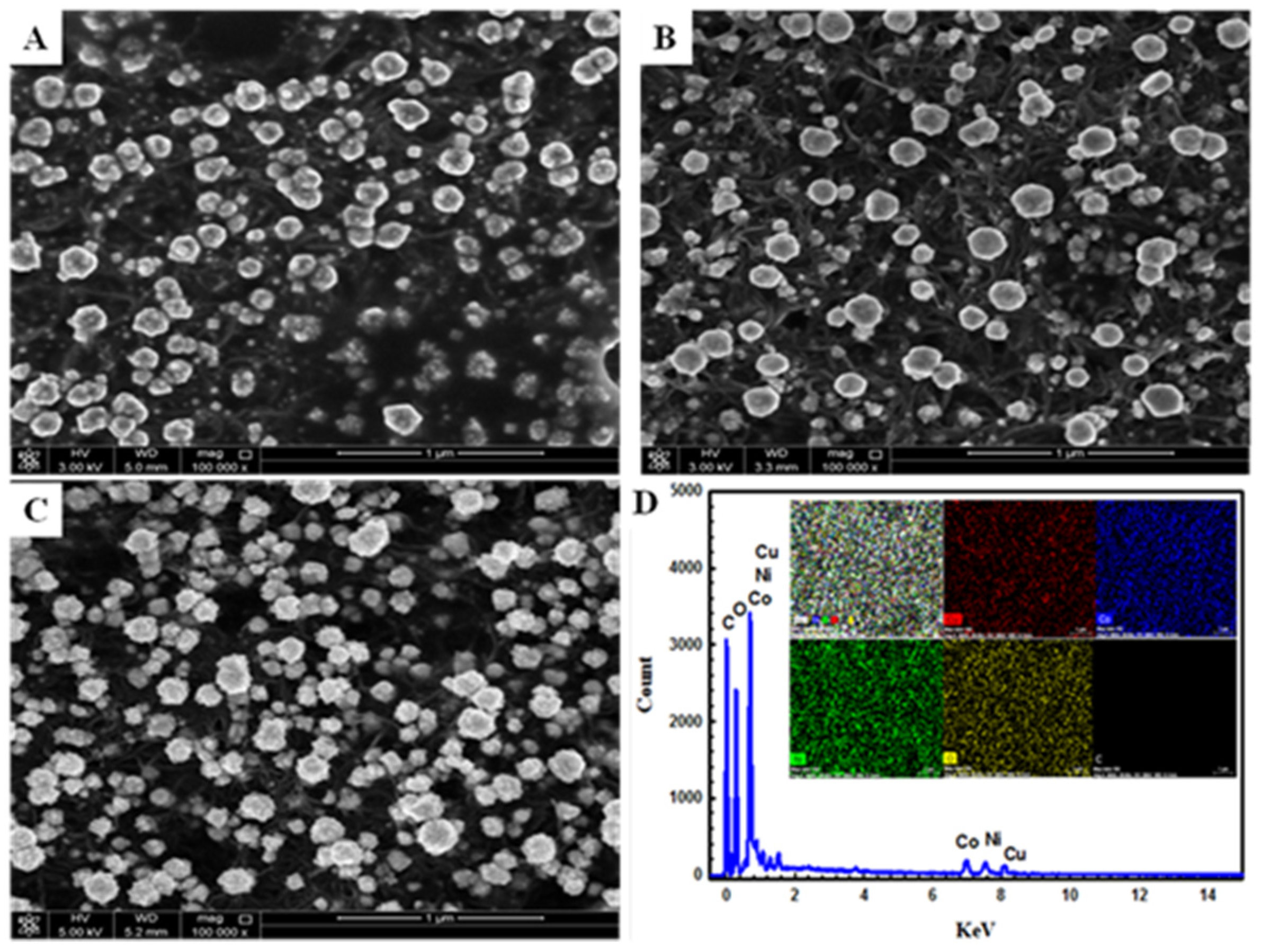
4.1. Materials and Electrochemical Characterization

Figure 1 represents the FE-SEM for CuCoNiOx@CNTs/GCE at (A) 600 s; (B) 900 s; and (C) 1200 s deposition time; as well as the (D) EDX analysis for sample (C). The SEM micrographs reveal that CuCoNi alloy is deposited throughout the CNTs’ texture as rough sphere-like shapes with poor distribution on the entire surface (SEM A, 600 s). When increasing the deposition time to 900 s, the rough sphere-like deposits’ diameter increases with enhancement of the deposits’ distribution through the surface. At 1200 s, the texture of the rough sphere starts to change to a cauliflower-like shape with noticeable high and uniform distribution. On the other hand, EDX is an important tool to quantify the deposits and to confirm the deposition of the different ingredients in the catalyst. The EDX chart (D) confirms the deposition of the three metal simultaneously by the revealed peaks of cobalt, nickel, and copper at 7.0 keV, 7.7 keV, and 8.1 keV, in weight percent quantities of 3.34, 3.47, and 1.5, respectively [8,19]. The mapping EDX (inset of (D) depicts the uniform distribution of the three metals inside the sample. The wide-angle XRD patterns of the prepared CuCoNiOx@CNTs/GCE were also carried out to explain the existing forms of the metal elements. As shown in Figure 2, the sharp peak located at around 25° corresponds to the (002) diffraction of the carbon substrate. According to the literature, Co, Ni, and Cu elements have similar negative electrons and atomic radiuses. Therefore, they can easily form the similar cubic structure. The (111), (200), and (220) peaks belonging to cubic system of Co, Ni, and Cu are 44.2°, 44.3°, 43.3°, 51.5°, 51.7°, 50.4°, and 76.0°. The XRD pattern revealed that the ternary alloy deposited has a cubic crystalline structure since the peaks from the characteristic cubic planes of (111), (200), and (220) were observed at 2θ ≈ 44.0, 51.0, and 76.0, respectively, suggesting that the CuCoNi system is a solid solution [26,27]. In addition, the peaks located around 2θ ≈ (37.0, 42.0) and 55.0 are attributed to NiOx and Co(OH)2 formation, respectively [27,28].
Figure 3 shows the CVs of (a) CNTs/GCE and (b–d) metal oxide modified CNTs/GCE in 1 M NaOH solution at a scan rate of 100 mV/s. The Voltammetric behavior of CNTs/GCE is featureless in the operating conditions of both potential and pH. While on the modification of CNTs/GCE with CoOx (CoOx@CNTs/GCE, curve b) reveals an anodic peak around +0.07 V and the corresponding small cathodic peak at the same value, and this can be attributed to the redox reaction [19],
Co 3 O 4 + OH + H 2 O 3 CoOOH + e
CoOOH + OH CoO 2 + H 2 O   + e
as long as there is a redox couple at about +0.45 V, which is related to the oxidation process of CoOOH to CoO2 following the equation [19].
On the other hand, CuOx@CNTs/GCE (curve c) shows a significant increase in the CV current starting around 0.25 V in the forward and backward directions, which is caused by conversion of the already formed Cu(II) at more negative potentials to Cu(III) according to the following equation [29],
CuO + OH CuOOH + e
At the NiOx@CNTs/GCE (curve e), the well-defined redox waves of the Ni(II)/Ni(III) transformation in alkaline medium is observed around 0.4 V, which leads to the formation of NiOOH according to [24],
Ni ( OH ) 2 + OH NiOOH + H 2 O + e
Furthermore, on the deposition of the tertiary metal oxides (CuCoNiOx@CNTs/GCE, curve d) several interesting features can be observed,
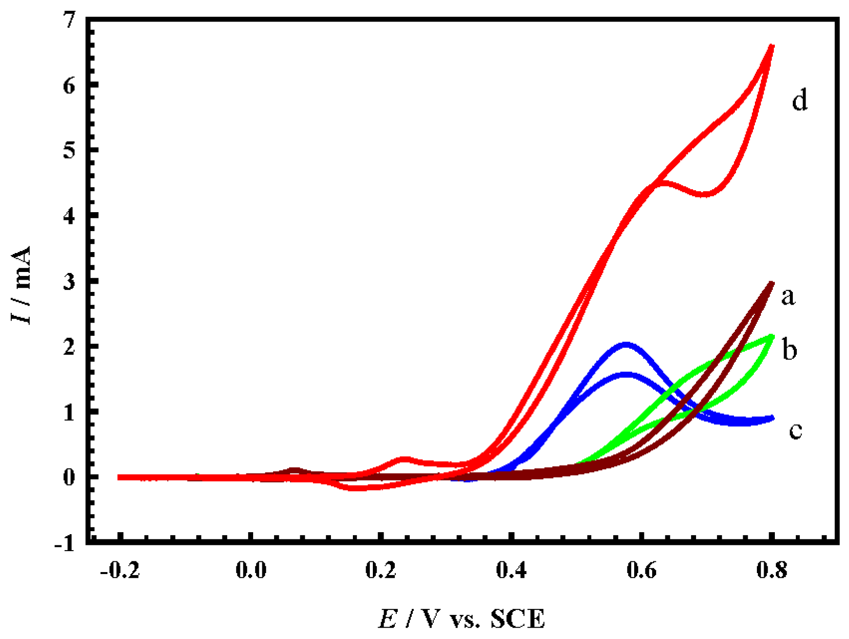
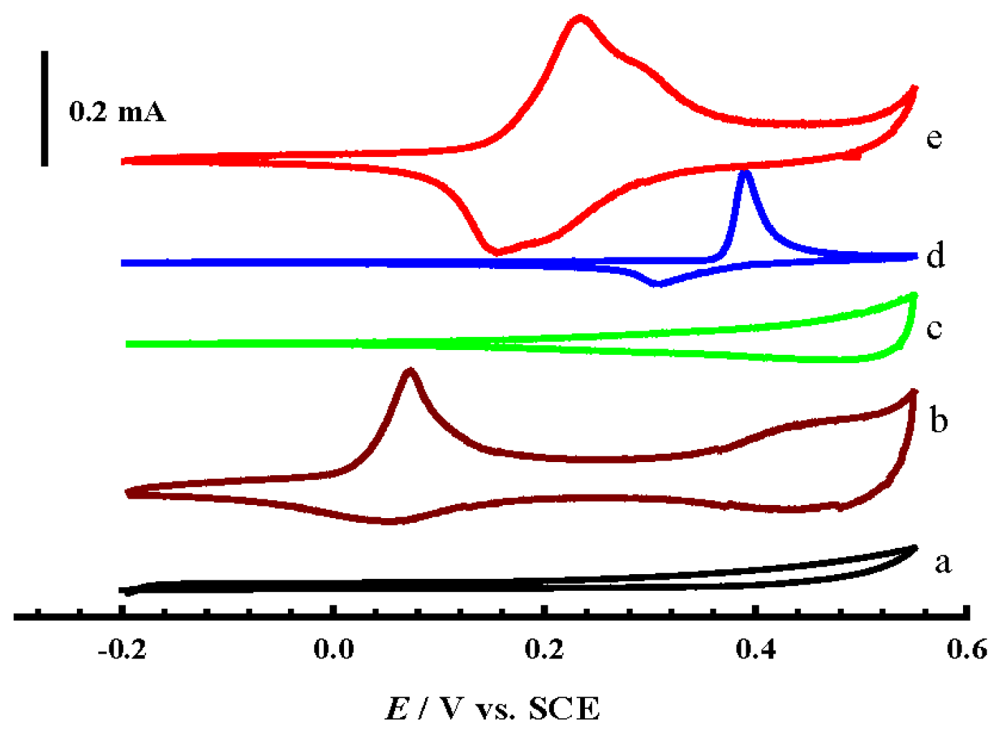
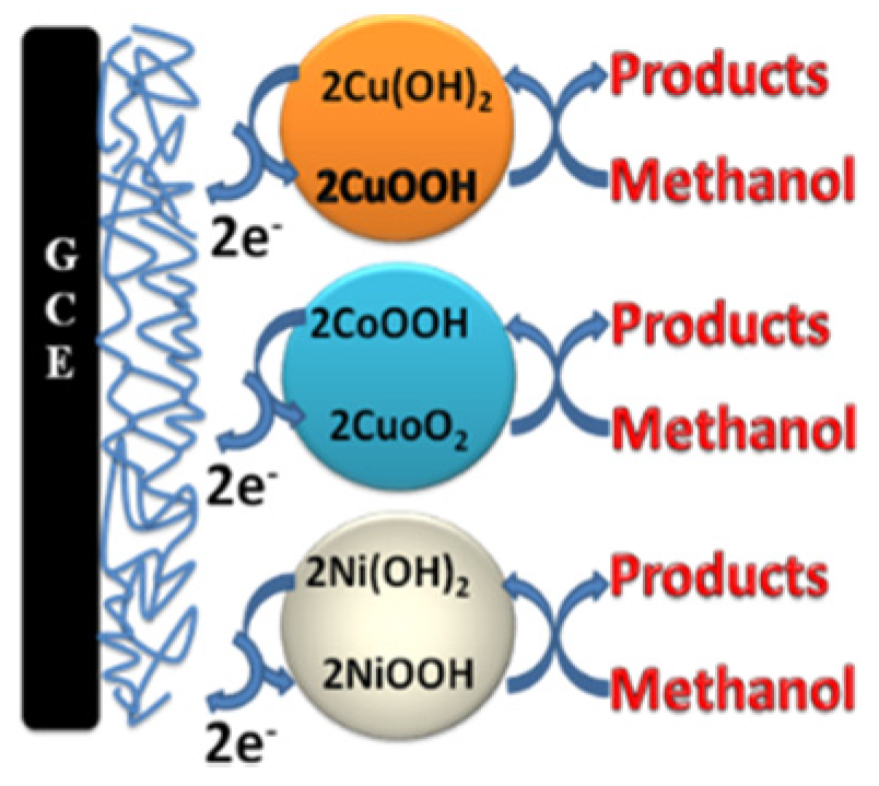
  • Firstly, the Ni(II)/Ni(III) transformation potential is negatively shifted by about 0.2 V in comparison to NiOx@CNTs/GCE (d), and this is attributed to the influence of a partial alloy or alloy structure, where the peaks of Ni(II)/Ni(III) and Co(II)/Co(III) of the formed alloy shifted negatively and positively, respectively [19].
  • Secondly, the charging current of the Ni(II)/Ni(III) transformation increased dramatically compared to the case of NiOx@CNTs/GCE, and this may be due to the synergism between NiOx and the other two oxides present at the same time that resulted in more transformation of Ni(II) to Ni(III). This enhanced transformation can be explained in the view of the results recorded in the literature previously, which assumed that mixing NiOx with other oxides to form binary alloys, for example MnOx, CoOx, or CuOx, causes an noticeable increase in the Ni(II)/Ni(III) transformation reaction [24,28,30]. This can be represented by Equation (6).
    N i 2 + + C u 2 + and / or   Co 3 + Ni 3 + +   Cu 1 +   and / or   Co 2 +
  • Thirdly, the charging current for both CuOx and CoOx, observed in the potential range 0.3 V to 0.55 V in curve b and c, decreased slightly in the same potential range in the case of CuCoNiOx@CNTs/GCE; this is certainly due to the last-mentioned feature in point II. Where, the high charging current in the mentioned potential range for both CuOx and CoOx is attributed to the conversion of Cu(II) and Co(III) to the higher oxidation states mentioned in Equations (3) and (4), and immediately the produced higher oxidation states are consumed in the Ni(II)/Ni(III) transformation according to Equation (6), so that no high charging current is observed.
The effect of the scan rate on the CuCoNiOx@CNTs/GCE electrode has been studied by recording CVs in 0.5 M NaOH at different scan rates (see Figure 4A). An increase in the peak currents was observed with increasing the potential scan rate. Figure 4B shows the variation of both anodic and cathodic peak currents with the scan rate. A linear relation between the peak current and the scan rate is obtained, indicating that the transformation process is a surface redox reaction [19].
Figure 5 shows the CVs for CuCoNiOx@CNTs/GCE at different deposition times in 1 M NaOH at a scan rate of 100 mV/s. In the case of CuCoNi@CNTs/GCE, as the deposition time of CuCoNi increases, the current for the redox transformation increases regularly, except for the last two deposition times, 1200 s and 1500 s, where the current difference is small. This may be due to the increase of the amount of deposit increases the time needed for the surface enrichment with oxides during the passivation step in alkaline medium. Also, by increasing the deposition time, the rate of crystal growth exceeds that of nucleation and results in the formation of bigger deposits rather than the formation of new crystals, which has a negative effect on the deposits’ accessible surface area, so the current does not increase directly [24]. On the other hand, with increasing the loading level of the deposit, the peak potential shifts slightly positive, and this could be attributed to the higher potential required for the nucleation of the upper oxides at these high loading levels [24]. Moreover, the peak of the transformation became sharp (i.e., small potential window of the peak) instead of broad at low loading levels, which confirms a fast kinetics of the transformation process.

4.2. Methanol Electrocatalytic Oxidation at the Modified Electrodes

Cyclic voltammograms (CVs) were taken in the presence of methanol in alkaline medium in order to study the impacts of the deposition of different metal oxides on methanol oxidation. Figure 6 compares CV responses obtained at CNTs/GCE modified electrodes where (a) CoOx@CNTs/GCE; (b) CuOx@CNTs/GCE; (c) NiOx@CNTs/GCE; and (d) CuCoNiOx@CNTs/GCE in 1 M NaOH containing 1 M methanol at a scan rate of 100 mV/s. Methanol oxidation at CNTs/GCE is not visible which indicates that CNTs/GCE is inert toward methanol oxidation in these conditions of pH and potential (data not shown), while with the modification of CNTs/GCE with any metal oxides, the catalytic activity is enhanced dramatically, which was concluded from the higher oxidation current obtained in the forward scan compared to the unmodified CNTs/GCE. As was expected, CoOx@CNTs/GCE (curve b) has shown the lowest electrocatalytic activity in comparison to the other oxides, and CuOx@CNTs/GCE (curve c) revealed better activity towards methanol oxidation than CoOx@CNTs/GCE, which was shown by higher current values and a negative shift in the onset potential of the methanol oxidation (I = 1.0 mA and 0.6 mA around 0.6 V for CuOx and CoOx, respectively). As reported in the literature, NiOx is one of the pioneer eletrocatalysts for alcohol oxidation in alkaline medium, and that appeared clearly in our work where NiOx@CNTs/GCE (curve d) showed the best catalytic activity for methanol oxidation among the addressed mono-catalysts, where there is a significant negative shift in the onset potential and increase in the oxidation current [9].
Generally, there are several mechanisms that are used to describe the methanol oxidation reactions on the metal oxides in alkaline medium and those reports can be shortened in two ways. The first assumes that the origin of the electrocatalytic activity of the CuOx, NiOx, and CoOx in alkaline medium is due to presence of the catalytic oxidizing agents of Cu(III), Ni(III), and Co(IV), respectively, that interact with methanol to form lower oxides and methanol oxidation products [31,32]. The second pathway assumes that methanol oxidation does not occur until complete formation of the mentioned higher oxidation states in the course of an anodic potential sweep, to be a support for the reaction and not a catalytic intermediate [33,34]. Therefore, in summary, we assume that a part of the anodic current is due to methanol oxidation by Cu(III), Ni(III), and Co(IV) and a part of the current is due to methanol oxidation on the surface of the oxide layer by direct electrooxidation. According to Jafarian et al. the mechanism can be written generally by following [8].
Lower   oxidation   state Higher   oxidation   state + e
And methanol is oxidized by the interaction with X(III) or X(IV) via the following routes:
Lower   oxidation   state + methanol Higher   oxidation   state + intermediate + e
Lower   oxidation   state + intermediate Higher   oxidation   state + products + e
In addition, the higher oxidation states are regenerated again by the power source and methanol is oxidized on these sites by direct electrooxidation according to the following:
Lower   oxidation   state methanol Higher   oxidation   state intermediate + e
Lower   oxidation   state intermediate Higher   oxidation   state products + e
Equations (8) and (9) relate to the first pathway mechanism [31,32], and Equations (10) and (11) relate to the second pathway mechanism [33,34].
As we mentioned in the introduction, NiOx is the best non-precious metal based eletrocatalyst for alcohol oxidation in alkaline medium, so research attention has been directed to enhance both NiOx stability and activity by alloying with other metal oxides. Interestingly, by addressing the electrocatalytic activity of the tertiary metal oxide CuCoNiOx@CNTs/GCE (curve e), significant features appear. The first feature is that the oxidation current increased dramatically in comparison to the mono-metal oxides (curves a, b, and c); this could be attributed to the synergism between the three metal oxides that resulted in enrichment of the surface with Ni(III), mentioned in Equation (5), which reflects the higher oxidation current in the forward scan according to the proposed mechanism in the above-mentioned equations, in addition to the fact that the presence of CuOx with NiOx in the same alloy enhanced the generation and stabilization of the β-NiOOH phase, the pioneer phase in the alcohol oxidation process in alkaline medium [18]. Furthermore, the higher produced oxidation current may be because of the fact that the three metals coexist in the same alloy and act as active sites for the methanol oxidation simultaneously. Moreover, the presence of CNTs as a support for the prepared ternary metal oxide, which affects the electrocatalytic activity of the catalyst by increasing the surface area and also by impeding the catalyst sintering and aggregation during the electrooxidation process of methanol, resulted in such high electrooxidation current. More specifically, in comparison to Rostami et al. [20], the presence of CNTs as a support resulted in a uniform distribution of the electrodeposited materials, which has a direct impact on surface area and this was clearly noticeable from the SEM images where the average particle size at 1200 s is around 200 nm in comparison to more than 1 µm for G/NiCuCo [20]. This effect on the particle size and distribution through the entire surface has a direct impact on the electrocatalytic activity. The second feature is a negative shift in the onset potential by about 50 mV; this is due to the alloying process that occurred between both CoOx and NiOx caused a negative shift in the Ni(II)/Ni(III) transformation according to the literature [19].
Note that, the mechanisms mentioned before for methanol oxidation are proposed for the single state oxide and in the case of the tertiary oxide, the mechanism is the same with the three oxides acting as active sites for the oxidation process at the same time, according to Figure 7. Figure 8 shows the variation of the reaction function (Ip1/2) with ν obtained at the CuCoNiOx@CNTs/GCE electrode for methanol electrooxidation. It is worthy to mention that with a scan rate more than 50 mV·s−1, Ip1/2 does not change significantly with the scan rate, which is a characteristic feature of catalytic reactions [35].

4.3. Effect of Loading Level

The extent of the CuCoNiOx deposition time has been investigated for CNTs/GCE, towards the electrocatalytic oxidation of methanol. Figure 9 compares the LSV recorded for methanol oxidation at different deposition times for CuCoNiOx@CNTs/GCE in 1 M NaOH containing 1 M methanol at a scan rate of 100 mV·s−1. It can be clearly seen that in the case of CuCoNiOx@CNTs/GCE, as the loading level increases, the current for the methanol oxidation increases as well, and this arises because of an increase of the active sites required for the oxidation process. In addition, there is a noticeable shrinkage in the current difference between the consecutive loading levels, and this may be attributed to some extent of agglomeration that may have occured at the higher loading levels. It is worth mentioning that the agglomeration and stability issues for the Cu alloy catalysts are critical for methanol production in addition to the methanol oxidation [36,37].

4.4. Long-Term Stability of the Prepared Electrocatalysts

One of the main aims of using tertiary oxide composed of CuOx, NiOx, and CoOx is to enhance the stability of the NiOx (the pioneer catalyst) modified CNTs/GCE. Therefore, to investigate the stability of the proposed catalysts, current-time (I-t) curves were recorded for methanol oxidation at the proposed electrodes at the peak potential, and the data are shown in Figure 10. This figure reveals that the mono-oxides have low stability towards methanol oxidation, while the CuCoNiOx@CNTs/GCE electrode shows higher oxidation current than that obtained with the three other electrodes. This coincides with the literature reports for the NiCo alloy [35]. This level of enhancement could still be observed after 30 min of continuous electrolysis. This indicates a better mechanical stability and good adhesion of the coexisting ternary oxide.

5. Conclusions

CuCoNi ternary alloy was successfully fabricated by simultaneous electrodeposition on CNTs@GCE and was tested for methanol electrooxidation in alkaline medium. Many features were found:
(I)
CuCoNiOx@CNT/GCE has shown the highest electrocatalytic activity and stability towards methanol electrooxidation in comparison to the mono catalysts. For example, a minimum 2.5 times enhancement in both stability and activity were found.
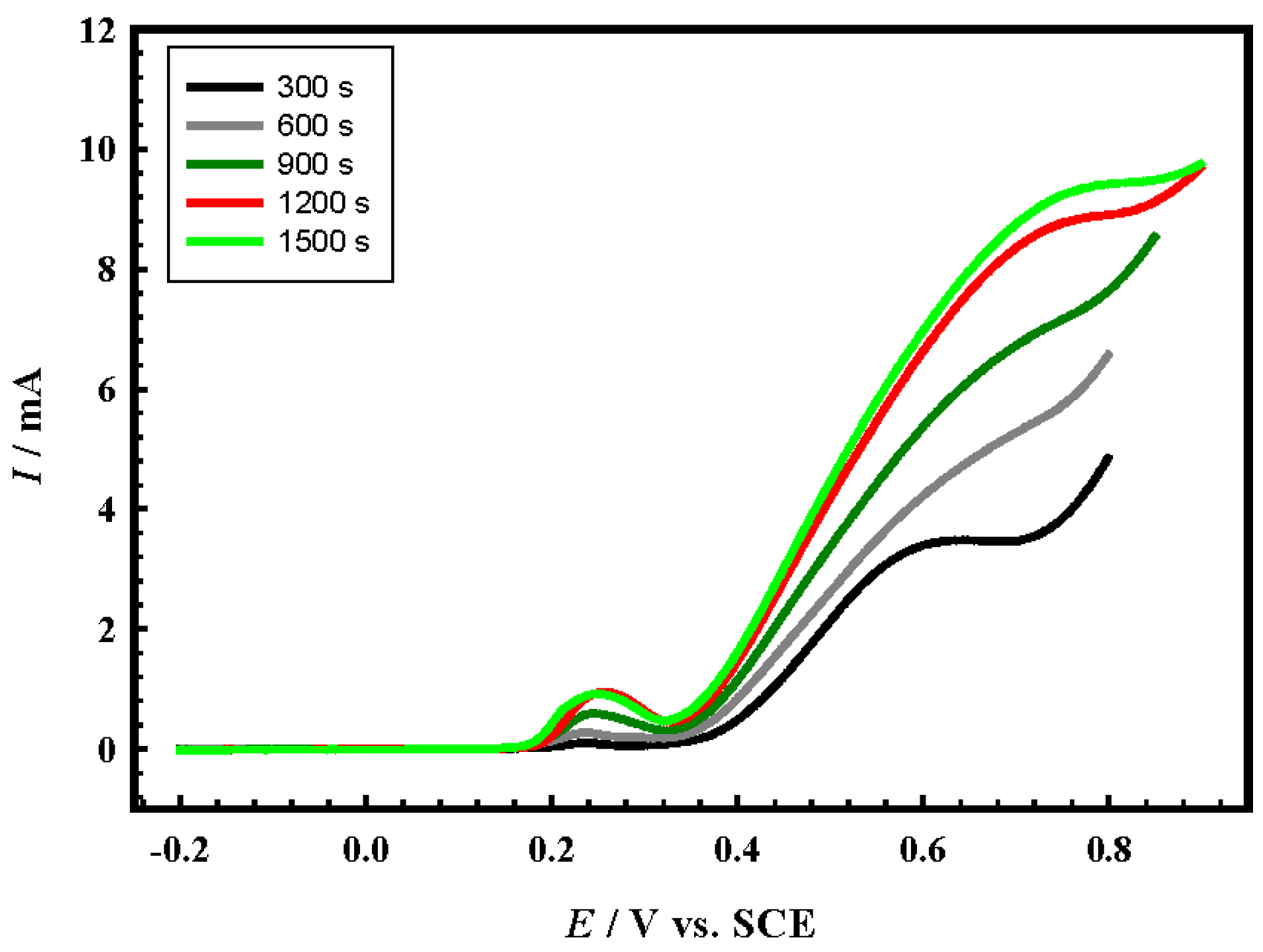
(II)
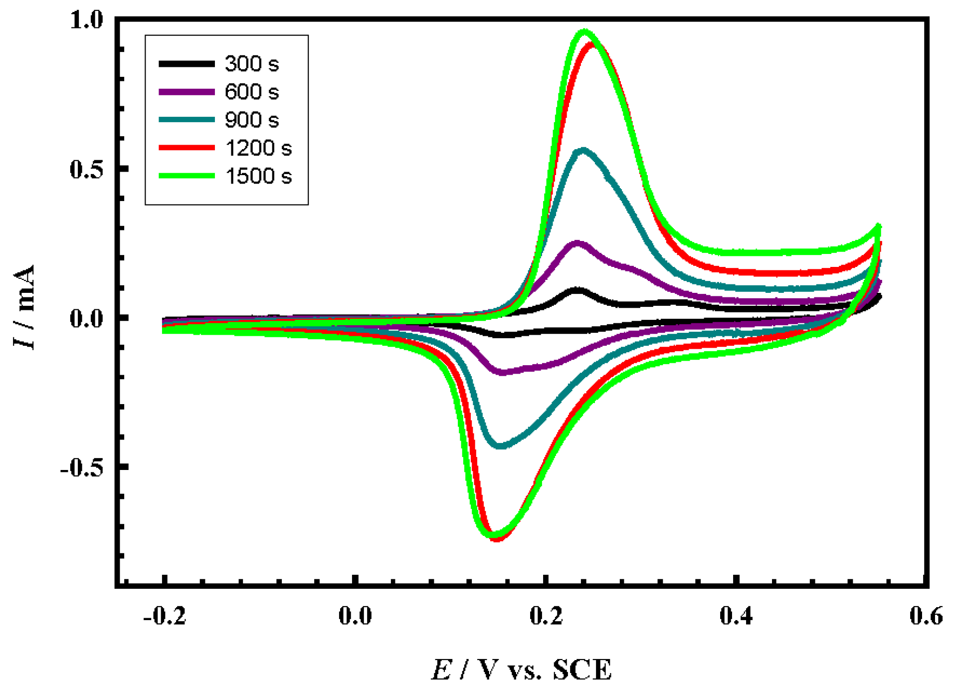
The electrocatalytic performance of CuCoNiOx@CNT/GCE depends greatly on the loading level (deposition time).
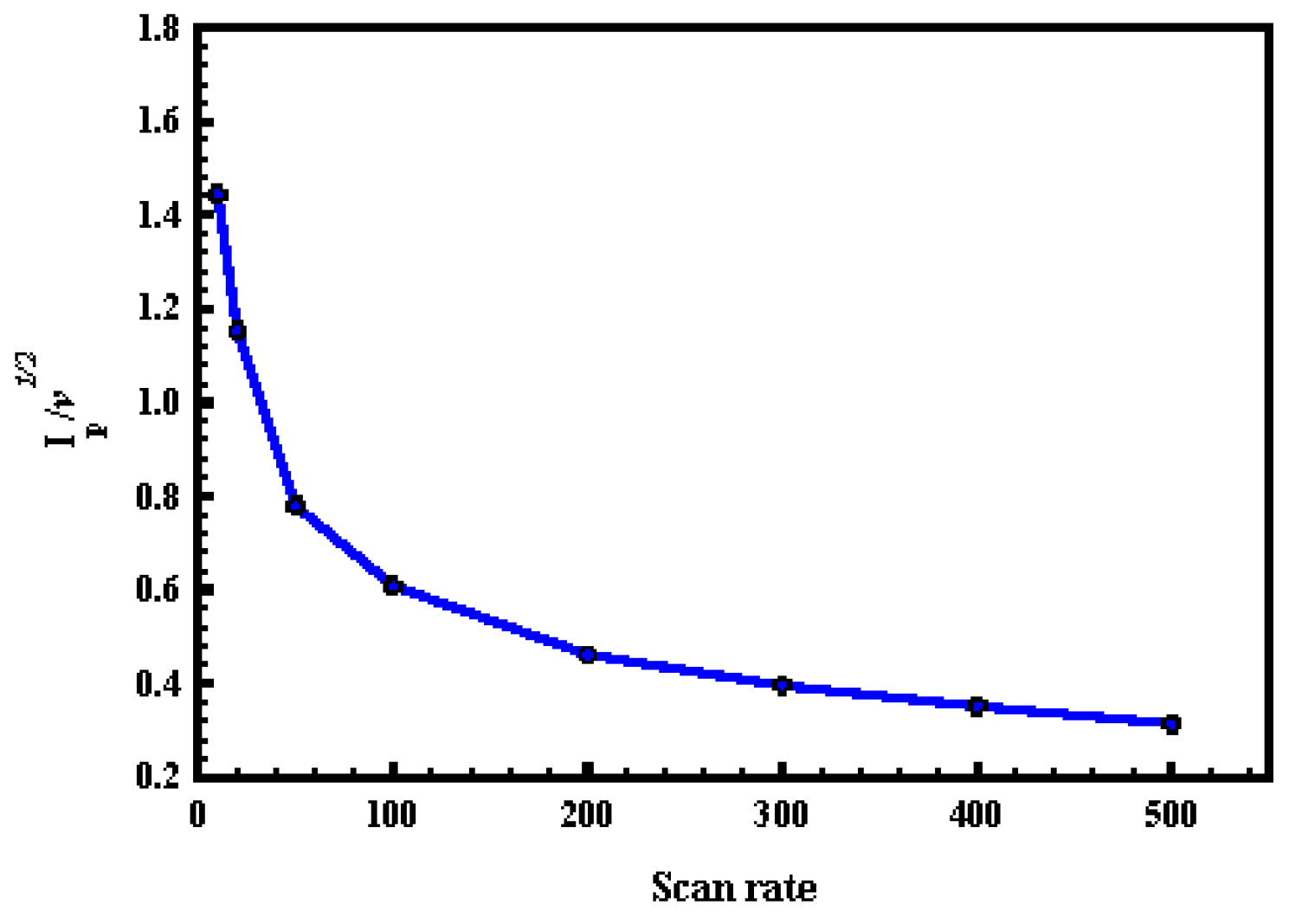
(III)
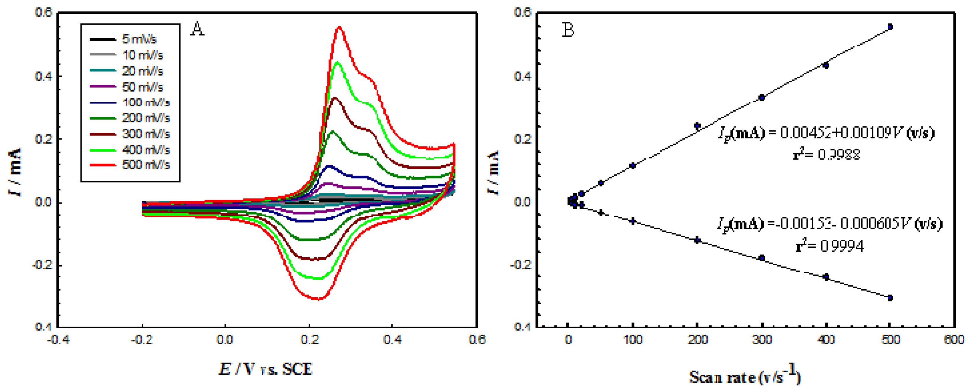
At a scan rate of more than 50 mV·s−1, the (Ip1/2) did not change significantly with scan rate, which is a characteristic feature of catalytic reactions.

Acknowledgments

The authors thank the Materials Science and Technology Program and the Center for Advanced Materials for supporting this study. Additionally, Aboubakr M. Abdullah thanks Cairo University in general and The Chemistry Department of the Faculty of Science specifically for the kind leave permission he was granted.

Author Contributions

A.M.A. and A.A.E. conceived and designed the experiments; A.A.H. and S.M.E.-R. performed the experiments; A.M.A. and S.M.E.-R. analyzed the data; A.A.E. and A.M.A. contributed reagents/materials/analysis tools; A.M.A. and S.M.E.-R. wrote the paper.

Conflicts of Interest

The authors declare no conflict of interest.

References

  1. Kamat, P.V. Energy Outlook for Planet Earth. J. Phys. Chem. Lett. 2013, 4, 1727–1729. [Google Scholar] [CrossRef] [PubMed]
  2. Sharaf, O.Z.; Orhan, M.F. An overview of fuel cell technology: Fundamentals and applications. Renew. Sustain. Energy Rev. 2014, 32, 810–853. [Google Scholar] [CrossRef]
  3. Wang, Y.; Chen, K.S.; Mishler, J.; Cho, S.C.; Adroher, X.C. A review of polymer electrolyte membrane fuel cells: Technology, applications, and needs on fundamental research. Appl. Energy 2011, 88, 981–1007. [Google Scholar] [CrossRef]
  4. Steele, B.C.H.; Heinzel, A. Materials for fuel-cell technologies. Nature 2001, 414, 345–352. [Google Scholar] [CrossRef] [PubMed]
  5. Li, X.; Faghri, A. Review and advances of direct methanol fuel cells (DMFCs) Part I: Design, fabrication, and testing with high concentration methanol solutions. J. Power Sources 2013, 230, 223–240. [Google Scholar] [CrossRef]
  6. Liu, H.; Song, C.; Zhang, L.; Zhang, J.; Wang, H.; Wilkinson, D.P. A review of anode catalysis in the direct methanol fuel cell. J. Power Sources 2006, 155, 95–110. [Google Scholar] [CrossRef]
  7. Zhao, H.; Law, K.-Y.; Sambhy, V. Fabrication, Surface Properties, and Origin of Superoleophobicity for a Model Textured Surface. Langmuir 2011, 27, 5927–5935. [Google Scholar] [CrossRef] [PubMed]
  8. Danaee, I.; Jafarian, M.; Forouzandeh, F.; Gobal, F.; Mahjani, M.G. Electrocatalytic oxidation of methanol on Ni and NiCu alloy modified glassy carbon electrode. Int. J. Hydrog. Energy 2008, 33, 4367–4376. [Google Scholar] [CrossRef]
  9. Tong, X.; Qin, Y.; Guo, X.; Moutanabbir, O.; Ao, X.; Pippel, E.; Zhang, L.; Knez, M. Enhanced Catalytic Activity for Methanol Electro-oxidation of Uniformly Dispersed Nickel Oxide Nanoparticles—Carbon Nanotube Hybrid Materials. Small 2012, 8, 3390–3395. [Google Scholar] [CrossRef] [PubMed]
  10. Heli, H.; Jafarian, M.; Mahjani, M.G.; Gobal, F. Electro-oxidation of methanol on copper in alkaline solution. Electrochim. Acta 2004, 49, 4999–5006. [Google Scholar] [CrossRef]
  11. Jafarian, M.; Mahjani, M.G.; Heli, H.; Gobal, F.; Khajehsharifi, H.; Hamedi, M.H. A study of the electro-catalytic oxidation of methanol on a cobalt hydroxide modified glassy carbon electrode. Electrochim. Acta 2003, 48, 3423–3429. [Google Scholar] [CrossRef]
  12. Liu, Y.-T.; Yuan, Q.-B.; Duan, D.-H.; Zhang, Z.-L.; Hao, X.-G.; Wei, G.-Q.; Liu, S.-B. Electrochemical activity and stability of core–shell Fe2O3/Pt nanoparticles for methanol oxidation. J. Power Sources 2013, 243, 622–629. [Google Scholar] [CrossRef]
  13. Orozco, G.; Pérez, M.C.; Rincón, A.; Gutiérrez, C. Electrooxidation of methanol on silver in alkaline medium. J. Electroanal. Chem. 2000, 495, 71–78. [Google Scholar] [CrossRef]
  14. Carugno, S.; Chassaing, E.; Rosso, M.; González, G.A. Enhanced electrochemical oxidation of methanol on copper electrodes modified by electrocorrosion and electrodeposition. Mater. Chem. Phys. 2014, 143, 1012–1017. [Google Scholar] [CrossRef]
  15. Hutton, L.A.; Vidotti, M.; Patel, A.N.; Newton, M.E.; Unwin, P.R.; Macpherson, J.V. Electrodeposition of Nickel Hydroxide Nanoparticles on Boron-Doped Diamond Electrodes for Oxidative Electrocatalysis. J. Phys. Chem. C 2011, 115, 1649–1658. [Google Scholar] [CrossRef]
  16. Xia, L.-P.; Guo, P.; Wang, Y.; Ding, S.-Q.; He, J.-B. Multi-laminated copper nanoparticles deposited on conductive substrates for electrocatalytic oxidation of methanol in alkaline electrolytes. J. Power Sources 2014, 262, 232–238. [Google Scholar] [CrossRef]
  17. Yang, M.; Jin, X.; Huang, Q. Electrochemical glucose oxidation on dendritic cuprous oxide film fabricated by PSS-assisted electrochemical deposition. Solid State Sci. 2011, 13, 427–433. [Google Scholar] [CrossRef]
  18. Jafarian, M.; Forouzandeh, F.; Danaee, I.; Gobal, F.; Mahjani, M.G. Electrocatalytic oxidation of glucose on Ni and NiCu alloy modified glassy carbon electrode. J. Solid State Electrochem. 2008, 13, 1171–1179. [Google Scholar] [CrossRef]
  19. Cui, X.; Guo, G.; Zhou, M.; Yang, Y.; Li, Y.; Xiao, P.; Zhang, Y.; Zhang, X. Promoting Effect of Co inNimCon (m + n = 4) Bimetallic Electrocatalysts for Methanol Oxidation Reaction. ACS Appl. Mater. Interfaces 2015, 7, 493–503. [Google Scholar] [CrossRef] [PubMed]
  20. Rostami, T.; Jafarian, M.; Miandari, S.; Mahjani, M.G.; Gobal, F. Synergistic effect of cobalt and copper on a nickel-based modified graphite electrode during methanol electro-oxidation in NaOH solution. Chin. J. Catal. 2015, 36, 1867–1874. [Google Scholar] [CrossRef]
  21. Linares, N.; Silvestre-Albero, A.M.; Serrano, E.; Silvestre-Albero, J.; Garcia-Martinez, J. Mesoporous materials for clean energy technologies. Chem. Soc. Rev. 2014, 43, 7681–7717. [Google Scholar] [CrossRef] [PubMed] [Green Version]
  22. Tan, C.W.; Tan, K.H.; Ong, Y.T.; Mohamed, A.R.; Zein, S.H.S.; Tan, S.H. Carbon Nanotubes Applications: Solar and Fuel Cells, Hydrogen Storage, Lithium Batteries, Supercapacitors, Nanocomposites, Gas, Pathogens, Dyes, Heavy Metals and Pesticides. In Environmental Chemistry for a Sustainable World: Volume 1: Nanotechnology and Health Risk; Lichtfouse, E., Schwarzbauer, J., Robert, D., Eds.; Springer: Dordrecht, The Netherlands, 2012; pp. 3–46. [Google Scholar]
  23. Al-Enizi, A.M.; Elzatahry, A.A.; Abdullah, A.M.; AlMaadeed, M.A.; Wang, J.; Zhao, D.; Al-Deyab, S. Synthesis and electrochemical properties of nickel oxide/carbon nanofiber composites. Carbon 2014, 71, 276–283. [Google Scholar] [CrossRef]
  24. El-Refaei, S.M.; Awad, M.I.; El-Anadouli, B.E.; Saleh, M. Electrocatalytic glucose oxidation at binary catalyst of nickel and manganese oxides nanoparticles modified glassy carbon electrode: Optimization of the loading level and order of deposition. Electrochim. Acta 2013, 92, 460–467. [Google Scholar] [CrossRef]
  25. Wang, L.; Zheng, Y.; Lu, X.; Li, Z.; Sun, L.; Song, Y. Dendritic copper-cobalt nanostructures/reduced graphene oxide-chitosan modified glassy carbon electrode for glucose sensing. Sens. Actuator B 2014, 195, 1–7. [Google Scholar] [CrossRef]
  26. Wang, C.; Li, W.; Lu, X.; Xie, S.; Xiao, F.; Liu, P.; Tong, Y. Facile synthesis of porous 3D CoNiCunano-network structure and their activity towards hydrogen evolution reaction. Int. J. Hydrog. Energy 2012, 37, 18688–18693. [Google Scholar] [CrossRef]
  27. Garcia-Cerada, L.A.; Bernal-Ramos, K.M.; Montemayor, S.M.; Quevedo-Lopez, M.A.; Betancourt-Galindo, R.; Bueno-Baques, D. Preparation of hcp and fcc Ni and Ni/NiO Nanoparticles Using a Citric Acid Assisted Pechini-Type Method. J. Nanomater. 2011, 2011. [Google Scholar] [CrossRef]
  28. Xu, W.; Zhang, H.; Li, G.; Wu, Z. Nickel-cobalt bimetallic anode catalysts for direct urea fuel cell. Sci. Rep. 2014, 4. [Google Scholar] [CrossRef] [PubMed]
  29. Priya, S.; Berchmans, S. CuO microspheres modified glassy carbon electrode as sensors materials and fuel cell catalysts. J. Electrochem. Soc. 2012, 159, F73–F80. [Google Scholar] [CrossRef]
  30. Ahn, S.H.; Park, H.-Y.; Choi, I.; Yoo, S.J.; Hwang, S.J.; Kim, H.-J.; Cho, E.; Yoon, C.W.; Park, H.; Son, H.; et al. Electrochemically fabricated NiCu alloy catalysts for hydrogen production in alkaline water electrolysis. Int. J. Hydrog. Energy 2013, 38, 13493–13501. [Google Scholar] [CrossRef]
  31. Fleischmann, M.; Korinek, K.; Pletcher, D. The oxidation of organic compounds at a nickel anode in alkaline solution. J. Electroanal. Chem. Interface Electrochem. 1971, 31, 39–49. [Google Scholar] [CrossRef]
  32. Fleischmann, M.; Korinek, K.; Pletcher, D. The kinetics and mechanism of the oxidation of amines and alcohols at oxide-covered nickel, silver, copper, and cobalt electrodes. J. Chem. Soc. Perkin Trans. 1972, 2, 1396–1403. [Google Scholar] [CrossRef]
  33. Taraszewska, J.; Rosłonek, G. Electrocatalytic oxidation of methanol on a glassy carbon electrode modified by nickel hydroxide formed by ex situ chemical precipitation. J. Electroanal. Chem. 1994, 364, 209–213. [Google Scholar] [CrossRef]
  34. Allen, J.R.; Florido, A.; Young, S.D.; Daunert, S.; Bachas, L.G. Nitrite-selective electrode based on an electropolymerized cobalt phthalocyanine. Electroanalysis 1995, 7, 710–713. [Google Scholar] [CrossRef]
  35. El-Refaei, S.M.; Saleh, M.M.; Awad, M.I. Enhanced glucose electrooxidation at a binary catalyst of manganese and nickel oxides modified glassy carbon electrode. J. Power Sources 2013, 223, 125–128. [Google Scholar] [CrossRef]
  36. Albo, J.; Sáez, A.; Solla-Gullón, J.; Montiel, V.; Irabien, A. Production of methanol from CO2 electroreduction at Cu2O and Cu2O/ZnO-based electrodes in aqueous solution. Appl. Catal. B Environ. 2015, 176–177, 709–717. [Google Scholar] [CrossRef] [Green Version]
  37. Albo, J.; Irabien, A. Cu2O-loaded gas diffusion electrodes for the continuous electrochemical reduction of CO2 to methanol. J. Catal. 2016, 343, 232–239. [Google Scholar] [CrossRef]
Figure 1. FE-SEM (field emission scanning electron microscope) for CuCoNiOx@CNTs/GCE(carbon nanotubes/glassy carbon electrode) at different deposition times (A) 600 s; (B) 900 s; (C) 1200 s; (D) Mapping EDX (Energy Dispersive X-ray) for Sample (C).
Applsci 07 00064 g001
Figure 2. XRD (X-ray diffraction) pattern of CuCoNiOx@CNTs/GCE.
Applsci 07 00064 g002
Figure 3. CVs (cyclic voltammetry) of different electrodes in 1 M NaOH solution at a scan rate of 100 mV/s: (a) CNTs/GCE; (b) CoOx@CNTs/GCE; (c) CuOx@CNTs/GCE; (d) NiOx@CNTs/GCE; and (e) CuCoNiOx@CNTs/GCE electrodes.
Applsci 07 00064 g003
Figure 4. (A) CVs of CuCoNi@CNTs/GCE in 1 M NaOH solution at different scan rates; (B) Variation of the anodic and cathodic peak currents with the scan rates.
Applsci 07 00064 g004
Figure 5. CVs of CuCoNi@CNTs/GCE at different deposition times in 1 M NaOH at a scan rate of 100 mV·s−1.
Applsci 07 00064 g005
Figure 6. CVs of different electrodes in 1 M NaOH + 1 M methanol solution at a scan rate of 100 mV·s−1: (a) CoOx@CNTs/GCE; (b) CuOx@CNTs/GCE; (c) NiOx@CNTs/GCE; and (d) CuCoNiOx@CNTs/GCE electrodes.
Applsci 07 00064 g006
Figure 7. Schematic illustration of the methanol electrooxidation reaction mechanism.
Applsci 07 00064 g007
Figure 8. Variation of Ip1/2 with ν for methanol electrooxidation obtained at CuCoNiOx@CNTs/GCE.
Applsci 07 00064 g008
Figure 9. CVs for CuCoNi@CNTs/GCE at different deposition times in 1 M NaOH + 1 M methanol solution at a scan rate of 100 mV·s−1.
Applsci 07 00064 g009
Figure 10. I-t transients for (a) CoOx@CNTs/GCE; (b) CuOx@CNTs/GC; (c) NiOx@CNTs/GC; and (d) CuCoNiOx@CNTs/GC in 1 M NaOH+1M methanol solution.
Applsci 07 00064 g010

