Article

Design and Experimental Development of a Pneumatic Stiffness Adjustable Foot System for Biped Robots Adaptable to Bumps on the Ground

1
State Key Laboratory of Robotics and System, Harbin Institute of Technology, Harbin 150080, China
2
Legs + Walking Lab, Shirley Ryan AbilityLab (Formerly the Rehabilitation Institute of Chicago), Chicago, IL 60611, USA
3
Feinberg School of Medicine, Northwestern University, Chicago, IL 60611, USA
*
Author to whom correspondence should be addressed.
Appl. Sci. 2017, 7(10), 1005; https://doi.org/10.3390/app7101005
Submission received: 20 August 2017 / Revised: 8 September 2017 / Accepted: 26 September 2017 / Published: 29 September 2017
(This article belongs to the Special Issue Bio-Inspired Robotics)

Abstract

:
Walking on rough terrains still remains a challenge that needs to be addressed for biped robots because the unevenness on the ground can easily disrupt the walking stability. This paper proposes a novel foot system with passively adjustable stiffness for biped robots which is adaptable to small-sized bumps on the ground. The robotic foot is developed by attaching eight pneumatic variable stiffness units to the sole separately and symmetrically. Each variable stiffness unit mainly consists of a pneumatic bladder and a mechanical reversing valve. When walking on rough ground, the pneumatic bladders in contact with bumps are compressed, and the corresponding reversing valves are triggered to expel out the air, enabling the pneumatic bladders to adapt to the bumps with low stiffness; while the other pneumatic bladders remain rigid and maintain stable contact with the ground, providing support to the biped robot. The performances of the proposed foot system, including the variable stiffness mechanism, the adaptability on the bumps of different heights, and the application on a biped robot prototype are demonstrated by various experiments.

1. Introduction

A two-legged mobile mechanism that can walk like a human is usually thought as the best suited locomotion method for robots aimed to coexist and collaborate with humans [1]. In the past few decades, bipedal robotic walking has been a hot area in the research of robotics [2,3,4,5]. In order to realize stable walking, the majority of existing biped robots are equipped with rigid flat feet and controlled by a trajectory tracking control method based on the zero moment point (ZMP) theory [6,7,8,9]. The ZMP theory requires that the location on the ground about which the sum of all the moments of the active forces acting on the robot equals zero is strictly within the support polygon of the foot sole [10]. Therefore, the foot that supports the body weight during walking is always kept flat on the ground to obtain the largest support polygon, especially in the single support phase where there is only one foot in contact with the ground [11,12]. The instantaneous speed of the foot touching the ground is desired to approximate to zero to reduce foot-ground impact. Although effective for walking on flat and structured terrains, this method will cause some problems if the ground is uneven. When a biped robot walks on rough terrain, just a small bump under the sole can significantly reduce the contact area and easily disrupt the walking stability, causing the robot to fall [13]. In addition, if the bump is unforeseen for the control system of the biped robot, the sudden impact with the bump may cause severe shock and vibration to the mechanical system. So several crucial issues involved in walking on rough terrains, such as adaptability on the unevenness, stable foot-ground contact, and shock absorbance still need further investigations.
To handle with the above challenges, some researchers focus on the studies of more advanced walking controllers for biped robots. Wei et al. proposed a landing phase control method based on the non-planar contact model of the flexible foot with the environment, and made the biped robot adaptable to the changes of the ground [14]. To achieve dynamic stable walking on rough ground, Nishiwaki et al. designed a high-frequency pattern generator which considered the current actual motion of the robot as the initial conditions of each generation [15]. In [16], a graph-based footstep planning approach was proposed to generate the whole step sequences in rough terrain scenarios using a black box walking controller. In [17], the preplanned trajectories were modified online to guarantee a smooth landing after the detection of the foot touching the uneven ground. However, the above controllers depended on some sensors, such as inertial measurement units, contact switches, or laser scanners, to obtain the robot motion state and terrain profile information. The sensor signals must be collected and processed correctly and reliably in real-time, and accurate models of robot kinematics, dynamics, foot-ground contact, and terrain shapes were usually required by the online walking pattern generation and modification. Additionally, as the integrations of on-board sensing, pattern generation, and walking control, the controllers had to perform very large computations at a very high speed [18]. These issues cause many difficulties in the implementations of the controllers.
On the other hand, considering that the foot is the only part of the whole biped robot that interacts directly with the environment, it is a feasible approach to improve walking performance on rough terrain through novel foot mechanisms. Some robotic foot systems were designed by adding toe joints and elastic elements to the simple rigid flat foot [19,20,21,22,23]. Segmented to the heel part and toe part, human-like heel contact and toe contact were realized in bipedal robotic walking [20]. These feet were able to dissipate energy from the heel strike with the elasticity of the heel [21,22], and to provide more traction using the toe pad at the push-off phase [23], but they could not adapt to rough terrain. Based on the concept of maintaining multi-point contact on uneven ground, a foot capable of providing stable contact on convex and concave surfaces was developed. The foot sole was equipped with four rigid spikes and corresponding locking mechanisms, each of which had an optical sensors to detect the ground height. According to the sensor values, the foot landing pattern was modified to guarantee a support polygon on uneven terrain with three or four spikes [24]. In [25], a flexible foot with 12 degrees of freedom was designed. Connected by four independently-actuated parts, the foot sole could maintain multi-point contact on complicated terrains. However, the adaptation was also actively controlled, which increased the complexity of the control system. In [26], Piazza et al. developed a completely passive foot by mimicking the longitudinal arch of human foot. The foot was able to vary its shape to comply with uneven terrains as a function of the exerted forces. However, its adaptation capabilities in the coronal plane and push-off movement were limited.
If we observe the human foot closely, we will find that when walking on the ground with trivial obstacles, the human foot sole can adapt to the irregularities passively without adjusting walking patterns or any active control. This is partly due to the intrinsic adaptivity of the soft tissues, such as the plantar fascia underneath the foot sole, which can soften and stiffen accordingly under different contact conditions. In this paper, we aim to design a new stiffness adjustable foot system for biped robots which is adaptable to small-sized bumps and obstacles on the ground on the basis of the inspirations from the human foot. Specifically, the foot can exert high stiffness to provide sufficient support and propulsion to the robot body during walking, and can also exert low stiffness to adapt to the bumps on the ground.
The rest of this paper is organized as follows: Section 2 introduces the working mechanism of the stiffness-adjustable foot system. Section 3 presents the design of the major components of the foot system in detail. Some preliminary experiments are performed to validate the functions of the foot system, and the results are shown in Section 4. Finally, some discussions and conclusions are given in Section 5.

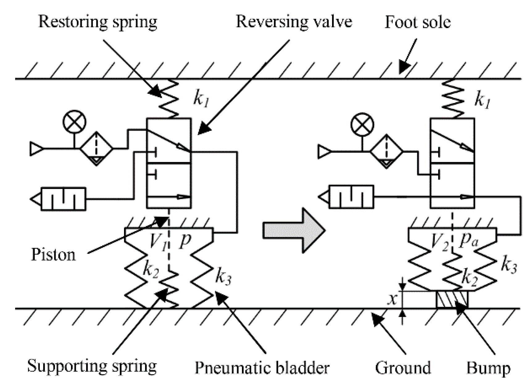
2. Working Mechanism of the Stiffness-Adjustable Foot System

2.1. Overview of the Stiffness-Adjustable Foot System

The central idea of the new foot system is the variable stiffness. This is achieved by attaching some pneumatic variable stiffness units (PVSUs) on the foot sole separately, as shown in Figure 1. Each PVSU mainly consists of a cylindrical pneumatic bladder and a stiffness-adjusting mechanism. In the default state, for example, when the foot is off the ground, the pneumatic bladders are set to high stiffness, being inflated with some compressed air. When the biped robot walks on rough ground with small-sized bumps and obstacles, the stiffness values of the pneumatic bladders may change accordingly with their contact conditions with the ground. Since there are some spaces among the PVSUs, if the bumps happen to be located in the spaces, all pneumatic bladders are just compressed slightly and still remain rigid. If some PVSUs come into contact with the bumps, the corresponding stiffness adjusting mechanisms are triggered to expel the air, making the pneumatic bladders soft, so that more deformation can be generated to comply with the shape of the bumps; meanwhile, the other pneumatic bladders which are in contact with the flat surface remain rigid. It should be noted that in order to reduce the control difficulty, the adjustment from high stiffness to low stiffness is purely passive, depending on the interactions between the pneumatic bladders and the bumps. Figure 2 shows the comparisons between a conventional rigid flat foot and the new foot when there are bumps and obstacles of various sizes and shapes on the ground (the sole of the new foot is set as transparent for clarity). For the flat foot, the posture around the three coordinate axes is greatly changed, which has to be compensated by the movement of at least three joints of other body parts to maintain multi-point contact. However, the new foot has the ability to adapt to the bumps and maintain sufficient contact area by means of its own adaptability.

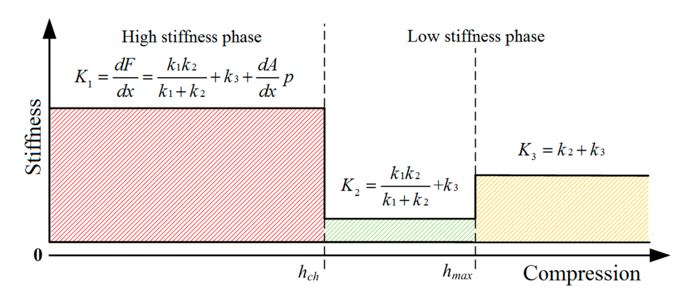
2.2. Theoretical Analysis of the Variable Stiffness Mechanism

The PVSU is the most crucial component of the whole foot system because the function of the foot depends on the interactions of each PVSU with the environment. This section introduces the variable stiffness mechanism of a single PVSU. Variable stiffness mechanisms have been more and more widely utilized in vibration isolation devices [27], humanoid robots [28], and rehabilitation devices [29]. Most recent work of variable stiffness mechanisms rely on two techniques. One is to alter the structural or mechanical geometry of an elastic mechanism [30], and the other is to change the elastic modulus of a structure by thermal or electromagnetic stimulation [31]. In this paper, the stiffness-adjusting mechanism of the PVSU is inspired by pneumatic artificial muscles, of which the stiffness can be changed by regulating the air pressure inside the muscles. Figure 3 illustrates the working principle diagram of a single PVSU interacting with the environment. The PVSU includes two major parts: a pneumatic bladder and a stiffness-adjusting mechanism. The stiffness-adjusting mechanism works based on a two-position three-port mechanical reversing valve. The PVSU is mounted underneath the foot sole through the reversing valve. The valve piston is connected with one end of the supporting spring, and the other end of the supporting spring is fixed on the bottom of the pneumatic bladder. The trigger signal of the reversing valve is the external force applied on the pneumatic bladder by the bump. In the normal position, the supply port of the reversing valve is connected with the pneumatic bladder. To trigger the valve, the external force needs to overcome the friction, the restoring spring, as well as the air pressure inside the pneumatic bladder. Once the trigger signal is off, the loaded restoring spring returns the valve to its original position.
The theoretical working process of the PVSU is as follows. In the swing phase of walking when there is no contact between the ground and the foot, the reversing valve is in normal position, supplying compressed air into the pneumatic bladder to keep it stiff. After transferring to the stance phase, the pneumatic bladder is compressed once touching the bump on the ground, and the valve piston is driven to move upward. As soon as the piston reaches the working position, the valve is triggered to expel the air out of the pneumatic bladder. Then, the pneumatic bladder becomes soft and generates more compression to comply with the shape of the bump.
When the PVSU interacts with the bump, compressions can be generated on any one of the restoring spring, supporting spring and pneumatic bladder. According to which elements are compressed, the entire compression process can be divided into three phases. During these phases, the PVSU has different configurations of series and/or parallel elastic elements, and exerts different stiffness values. Prior to analyzing the stiffness in each phase, several assumptions are made to simplify the modeling problem by referring to the mathematical models of air-supported structures and air springs [32,33,34], specifically, (1) the foot sole, the ground and bumps are perfectly rigid and cannot generate deformation under external forces; (2) the damping effects of the elastic elements are negligible considering that the damping factors are much smaller than stiffness factors [35]; (3) the compression of the PVSU is taken as a quasi-static behavior; (4) the static pressure inside the bladder is assumed to remain stable during each phase; and (5) the inflation and deflation, in other words, the changes of air pressure inside the pneumatic bladder are completed instantaneously.
The first phase starts when the pneumatic bladder touches the bump and ends when the piston arrives at its working position. During this phase, the restoring spring, supporting spring, and the inflated pneumatic bladder are compressed simultaneously. Similar to pneumatic artificial muscles, the stiffness of the pneumatic bladder is dependent upon two factors: one is the inherent stiffness of the bladder in the natural state without inflation, which is determined by its material properties and mechanical structure, and the other is the stiffness that relates to the air pressure inside the bladder [36]. Stiffness of a body can be defined as the infinitesimal force variation with regards to resulting compliant displacement [37]. If we assume F be the external force acted on the pneumatic bladder, and x is the corresponding amount of compression, then the system stiffness of the PVSU in the first phase can be described as:
K 1 = d F d x = k 1 k 2 k 1 + k 2 + k 3 + d ( p A ) d x = k 1 k 2 k 1 + k 2 + k 3 + p d A d x
where k1, k2, and k3 indicate the stiffness values of the restoring spring, the supporting spring, and the bladder, respectively, A represents the effective circumferential cross-sectional area of the pneumatic bladder, and p represents the air pressure inside the bladder.
When the reversing valve is triggered, the air inside the pneumatic bladder is expelled quickly. Then the compression process enters the second phase and lasts until the piston moves to its limit position. The restoring spring, supporting spring, and pneumatic bladder are all compressed, but the pressure inside the pneumatic bladder is changed to ambient pressure which is represented by pa. The system stiffness is expressed by:
K 2 = k 1 k 2 k 1 + k 2 + k 3
The third phase starts as soon as the piston reaches its limit and the restoring spring cannot be compressed anymore. As the external force continues to increase, only the supporting spring and pneumatic bladder undergo further compression. The system stiffness of this phase is given by:
K 3 = k 2 + k 3
It should be noted that this section is focused on the introduction of the variable stiffness mechanism in principle, rather than the investigation of the accurate analytical model of the PVSU. Thus, only simple stiffness expressions are provided above. The variable stiffness of the PVSU in the entire compression process is illustrated in Figure 4. The first phase which has the largest stiffness is also termed as the high stiffness phase, and the second and third phases are termed as low stiffness phases. In this figure, hch and hmax represent the trigger displacement and the maximum displacement of the valve piston, respectively.

3. Development of the Stiffness Adjustable Foot System

The stiffness-adjustable foot system is designed step by step, i.e., from the pneumatic bladder to the PVSU, then to the whole foot. This section presents the development of the foot system in detail.

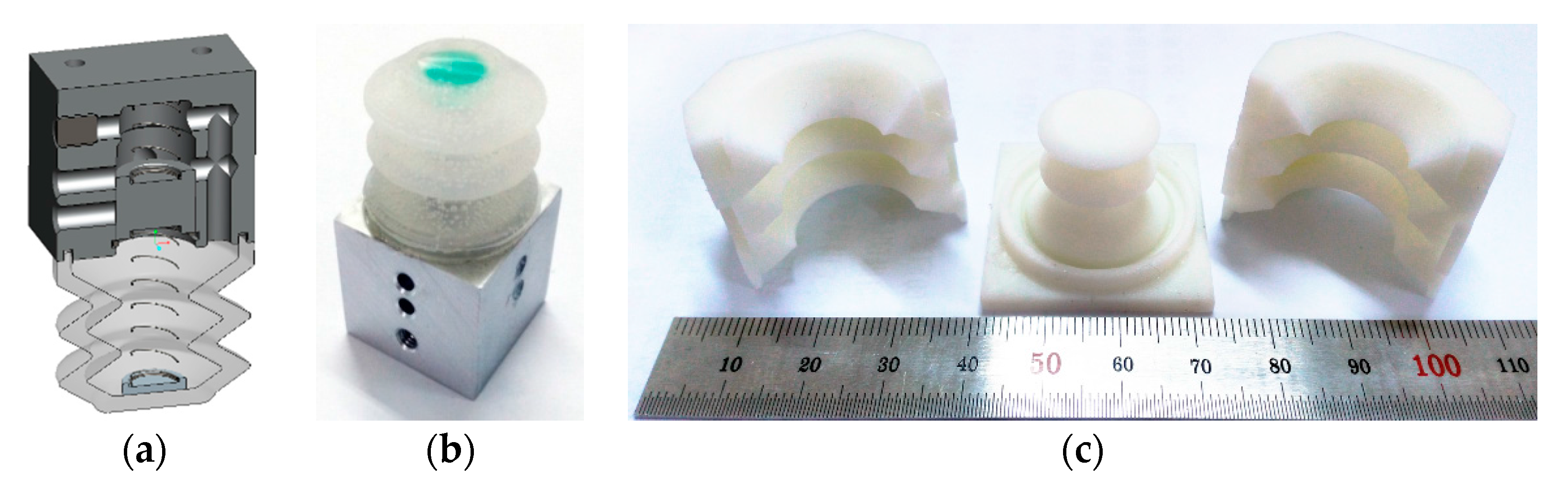
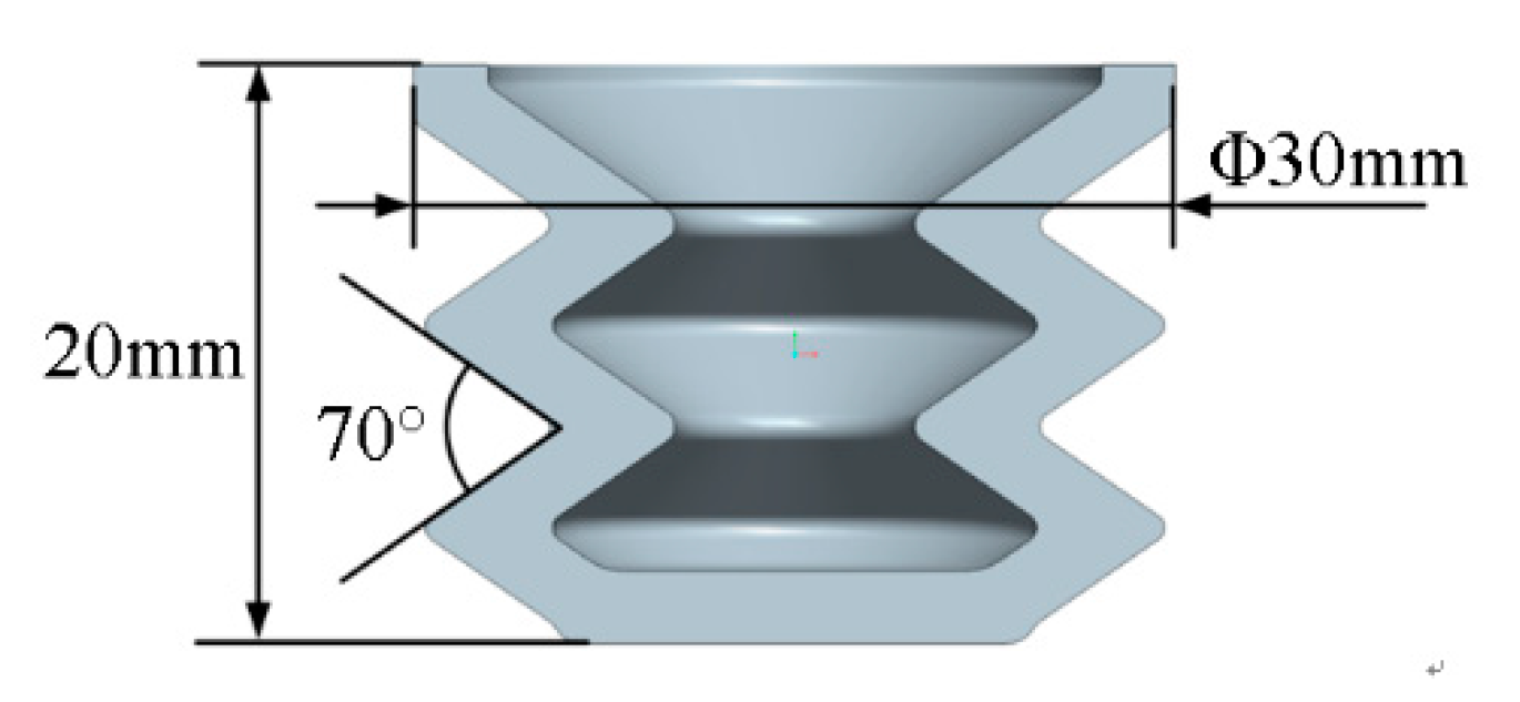
3.1. Design of the Pneumatic Bladder

The main structure parameters of the saw-toothed pneumatic bladder include material, diameter, total height, wall thickness, and the angle of the sawtooth. The following points must be taken into account to obtain an appropriate structure: (1) the pneumatic bladder should be stiff enough to hold its shape; (2) the axial deformation after inflation should be homogeneous, while circumferential deformation should be as small as possible; (3) the stiffness of the pneumatic bladder should have good linearity; and (4) the structure of the molds should be considered at the same time.
Finite element analysis is carried out in ANSYS (ANSYS Inc., Canonsburg, PA, USA) for parameter optimization. Applying a pressure load on the virtual model of the pneumatic bladder, deformations under various parameter configurations can be obtained. After trial and error, some key parameters are determined, as shown in Figure 5. The material type is silica gel, the diameter is 30 mm, the total height is 20 mm, and the angle of the sawtooth is 70°.
Furthermore, the hardness of silica gel and the wall thickness, which greatly affect the stiffness of the pneumatic bladder, still need to be determined. The possible values of hardness and wall thickness under consideration are Shore 35A, Shore 40A, 2 mm, and 2.5 mm. The stiffness of the pneumatic bladder under different combinations of hardness and wall thickness is simulated in ANSYS. The simulation results illustrated in Figure 6 show that the stiffness increases with larger hardness and/or wall thickness. In addition, once the hardness and wall thickness are determined, the stiffness is approximately a constant value. On this basis, because the pneumatic bladder is desired to have enough stiffness, Shore 40A and 2.5 mm are selected as the material hardness and wall thickness. The theoretical maximum compression of the pneumatic bladder is 8 mm.

3.2. Design of the PVSU

In the design of the PVSU, there exist the following major structure parameters: the trigger displacement of the piston, the maximum displacement of the piston, and the stiffness of the restoring spring and the supporting spring. The trigger displacement of the piston has important effects on the support ability of the foot, i.e., a higher value means larger external force demanded to trigger the reversing valve, and lower adaptability on rough terrains. In this paper, it is chosen as 2 mm. The maximum displacement of the piston which mainly determines the restoring speed of the piston is set as 4 mm.
Then, the remaining two structural parameters need to be optimized. As before, the finite element analysis method is utilized. The inside pressure load and external force load are applied on the pneumatic bladder which is modelled in ANSYS. Adjusting the stiffness of the restoring spring and the supporting spring, the corresponding displacement of the piston is simulated. According to the analysis, the stiffness values of restoring spring and supporting spring are selected as 0.098 N/mm and 0.975 N/mm, respectively.
After the key parameters are confirmed, the structure of the reversing valve is designed. The overall dimension of the valve is 25 mm × 25 mm × 22 mm. The diameter and height of the piston are both 10 mm. The material of the valve body is 2024 aluminum alloy, and the material of the piston is 304 stainless steel. In addition to the three necessary working ports, an auxiliary port is added inside the valve for quick exhaust. Figure 7a,b show the sectional view and the prototype of the PVSU. In this paper, the pneumatic bladder is manufactured by injecting the liquids of silica gel into the molds. Figure 7c presents the 3D-printed molds developed for the pneumatic bladder.

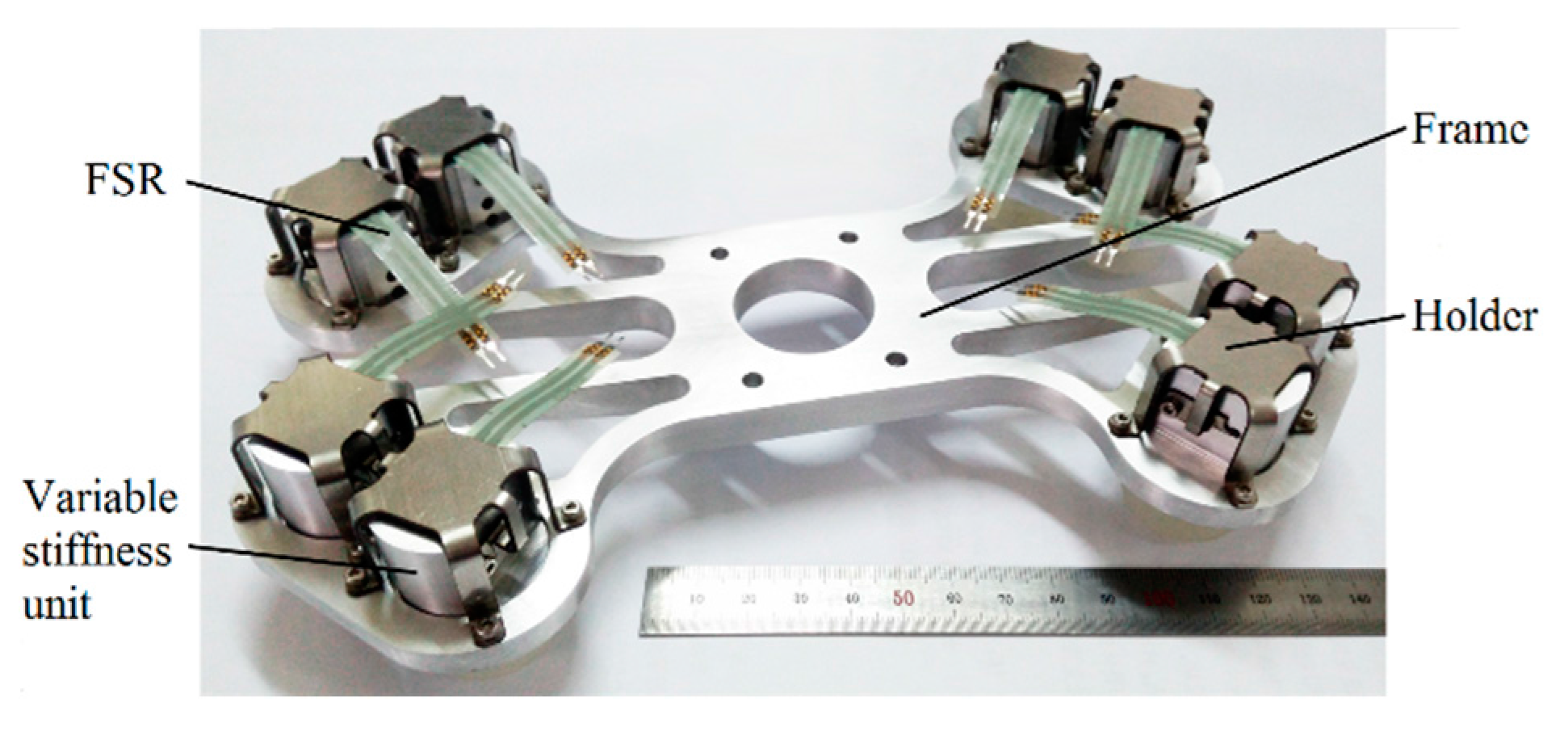
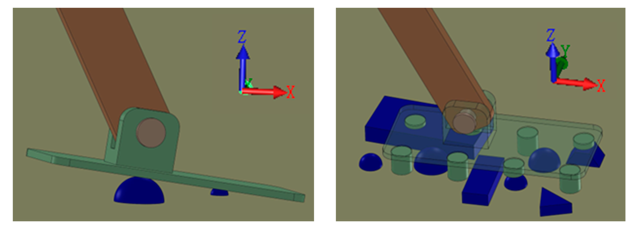
3.3. Design of the Foot System

As introduced previously, the foot is designed basically by attaching some PVSUs to the sole. The configuration of these PVSUs on the foot should meet the following requirements, i.e., the foot should have as high adaptability to rough terrain as possible and, at the same time, have the ability to offer stable support to the body weight. The prototype of the foot system is illustrated in Figure 8. In total, there are eight PVSUs symmetrically equipped on the four corners of the foot sole. Each PVSU is fixed on the foot frame through a holder. Between these PVSUs and holders are force-sensitive resistors (FSRs) which are utilized to measure the pressure distribution under the sole. Redundant materials of the frame are cut off to keep weight down, making the total weight as low as about 200 g. Through the flange located on the middle part, the foot system can be conveniently equipped on a biped robot.

4. Experiments

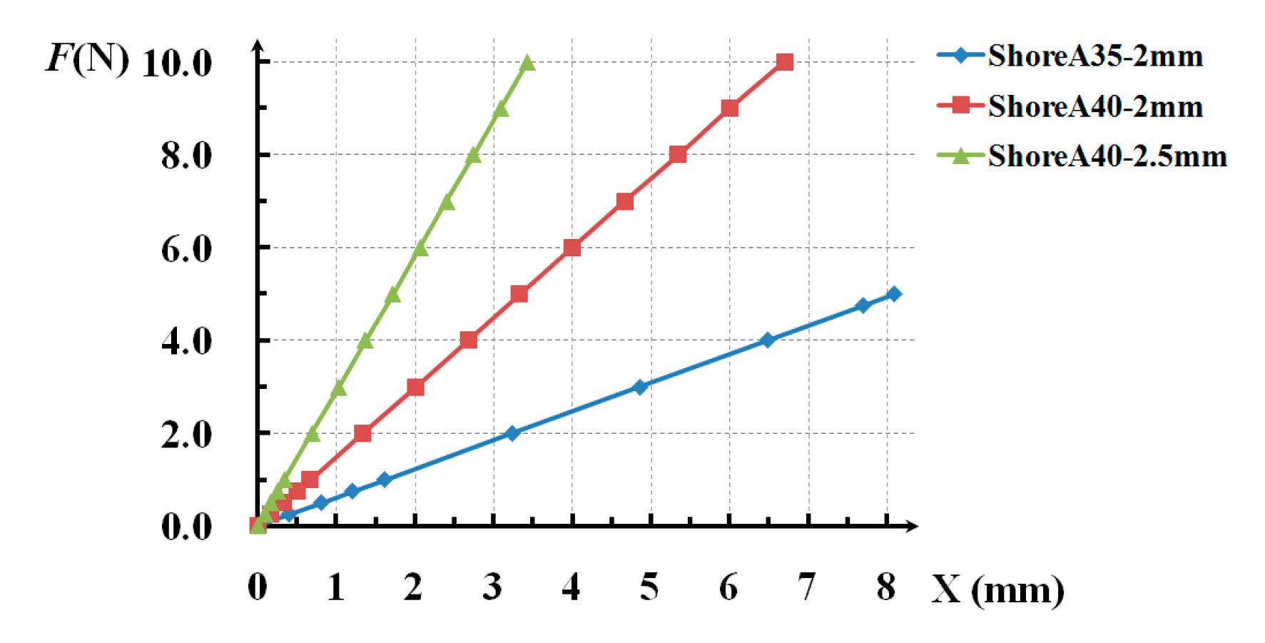
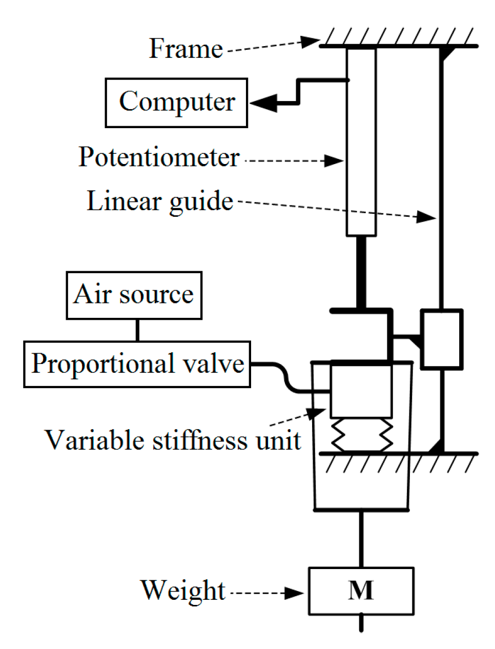
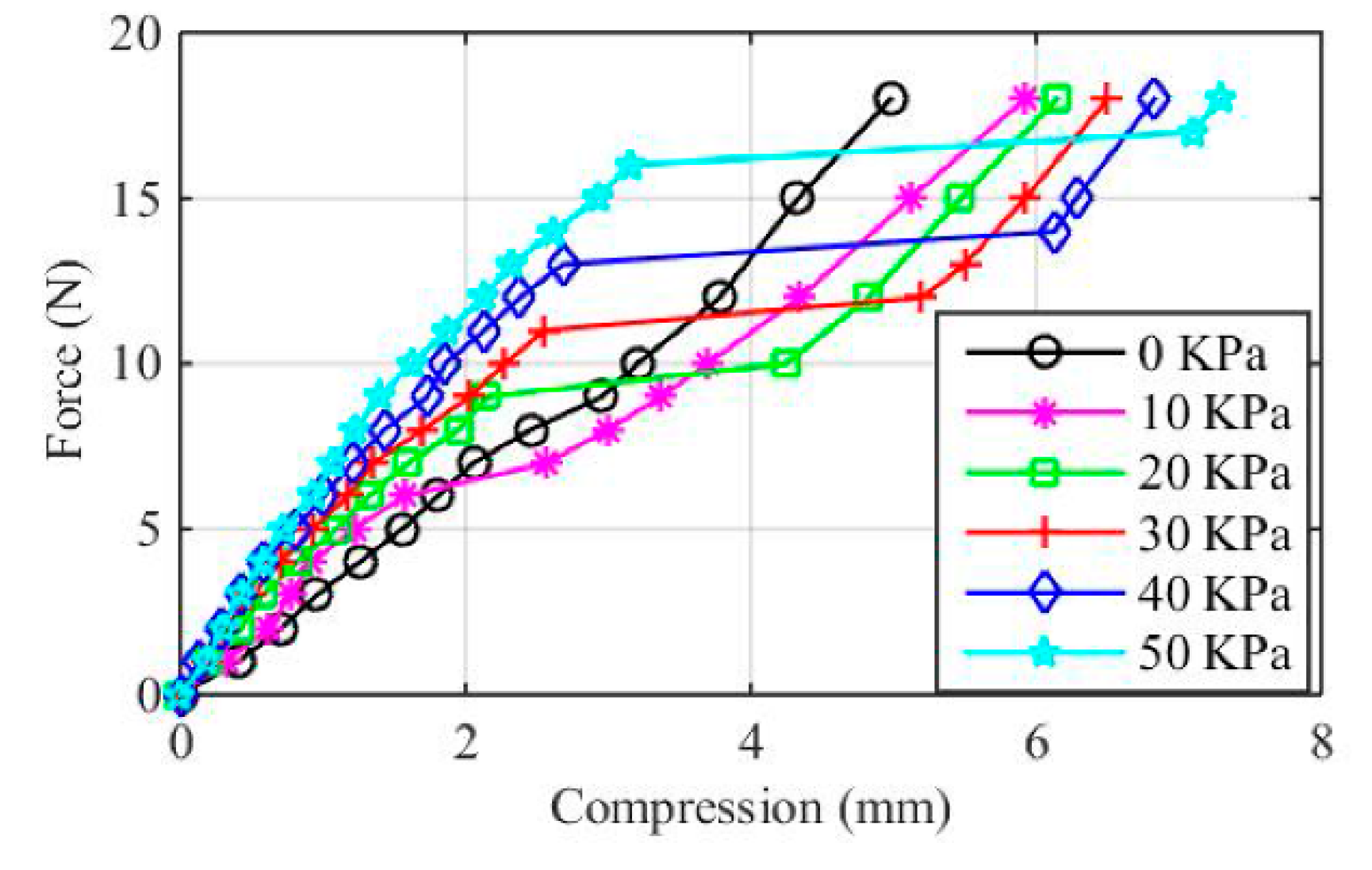
4.1. Experiment on the PVSU

The purpose of this experiment is to verify the variable stiffness mechanism of the PVSU by testing its static stiffness. As mentioned previously, stiffness can be defined as the ratio of steady force acting on a deformable elastic medium to the resulting displacement. Thus, the relation between the forces and resulting displacements when constant pressure is applied to the PVSU is examined in the stiffness identification experiment. Figure 9 presents the schematic diagram of the experimental apparatus. The PVSU is placed on a frame, and its upper end is connected with a slider which can only move along the linear guide in the vertical direction. Below the whole PVSU hangs a weight which causes the PVSU to be compressed. A proportional valve (SMC Corp., Tokyo, Japan) is adopted to regulate the air pressure supplied into the pneumatic bladder. The compression of the PVSU is measured by a linear displacement potentiometer (Novotechnik Messwertaufnehmer OHG, Ostfildern, Germany) installed in parallel with the linear guide, and collected and recorded by data acquisition devices (Advantech Co., Ltd., Taipei, Taiwan) on the computer for further analysis.
At the start of the experiment, the gauge pressure of the proportional valve was set to zero. Then different weights ranging from 0 to 1.8 kg were applied to the PVSU at a constant increment of 0.1 kg. The weight was changed after the compression of the PVSU stabilized. Corresponding compressions during the process were measured. After that, the above process was repeated in different cases where the gauge pressure was 10 KPa, 20 KPa, 30 KPa, 40 KPa, and 50 KPa, respectively.
After experiments, the relationship between the external loads and the compressions is plotted in Figure 10. From this figure, several findings can be obtained. Firstly, in the point of the response of the PVSU under a certain gauge pressure, it is evident that each curve can be approximately regarded as three segments of straight lines, which signifies that three phases were indeed presented within the entire compression. Secondly, since the slope of the line indicates the system stiffness, the three-segmented curve means that the PVSU exerted different stiffness values during the three phases. Moreover, the stiffness of the second segment is lower than the first one, and the stiffness of the third segment is higher than the second one. This trend coincides exactly with the theoretical analysis in Section 2. Thirdly, the horizontal ordinate of the turning point of each curve is exactly the trigger displacement of the piston. Under different gauge pressures, the trigger displacement of the piston ranges from 2 mm to 3 mm, which is very close to the design value. Synthesizing the above three points, the proposed variable stiffness mechanism, as well as its mechanical structure, can be proved to be feasible.
In addition, comparing all the measured curves under different gauge pressures, it shows that as the gauge pressure goes up, the piece-wise linearity of the stiffness becomes more obvious, and both the stiffness value in the high stiffness phase and the amount of compression in the low stiffness phase increase. Higher stiffness in the high stiffness phase means more stable support can be provided to the robot body when the foot is in contact with the ground, while a larger compression range in the low stiffness phase means larger unevenness that the pneumatic bladder is able to adapt to, which are exactly what we want. On this basis, taking the stiffness, adaptability, and pressure endurance into consideration together, 50 KPa is adopted as the ideal working pressure of the PVSU.

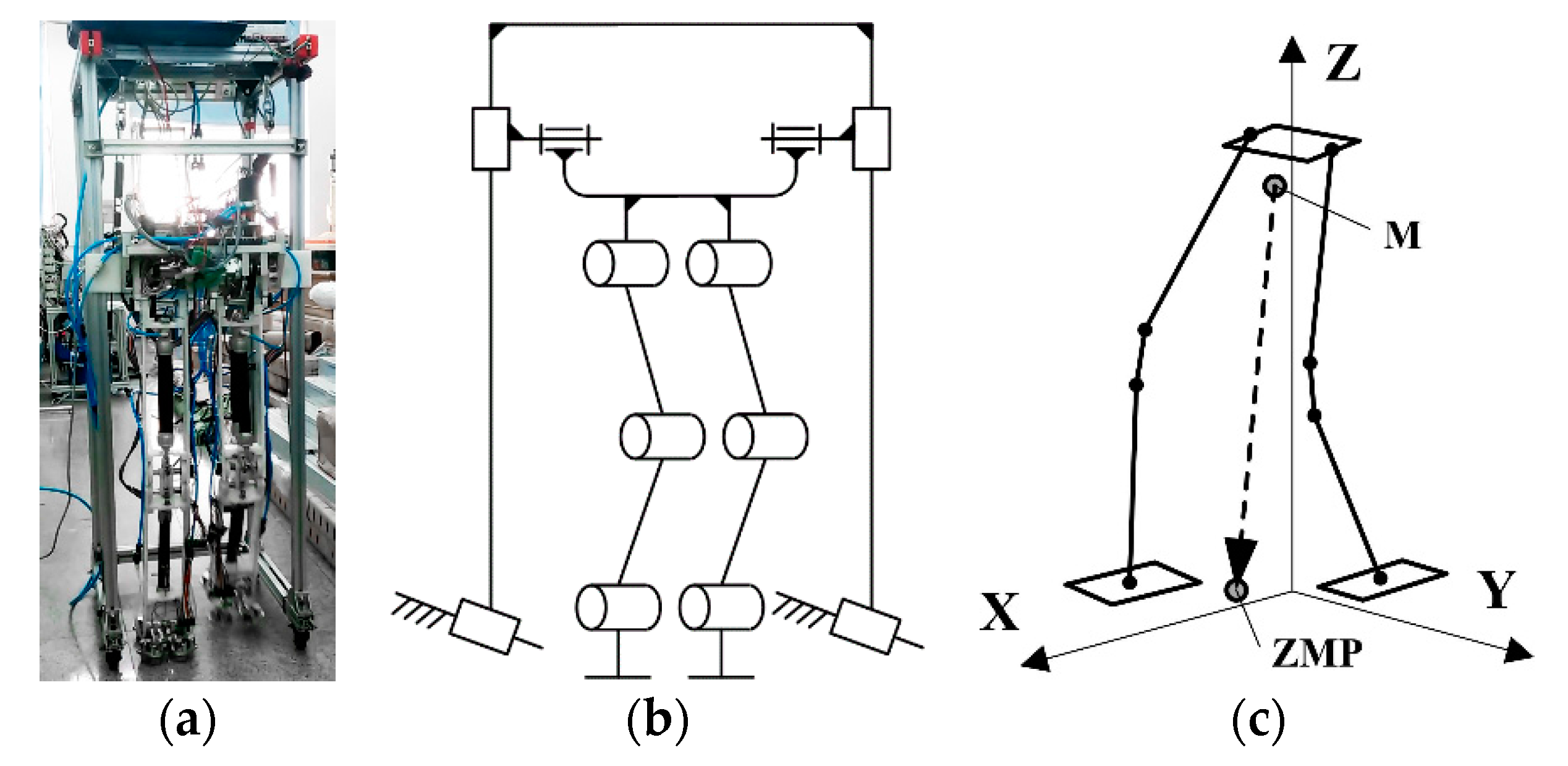
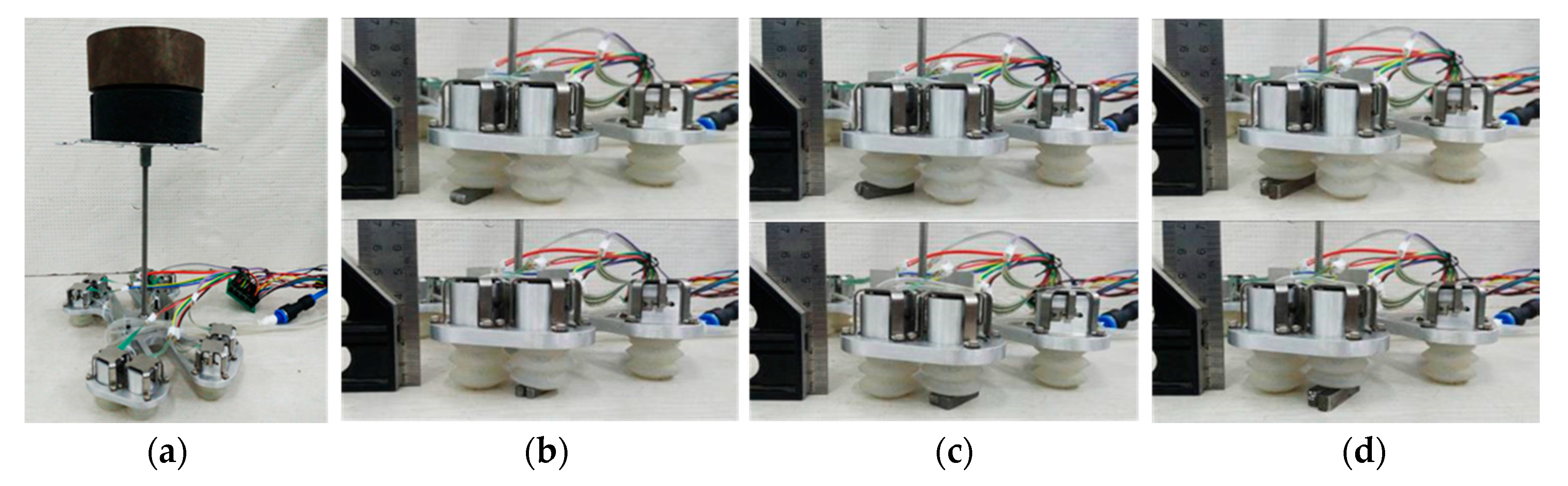
4.2. Experiment on the Foot System

The most important function of the proposed foot system is to adapt to small-sized bumps on the ground with the help of the PVSUs and, thus, to reduce the change in the posture of the sole and maintain stable foot-ground contact. Several requirements must be met to guarantee the performance of the foot system, specifically, (1) the reversing valves of the PVSUs in contact with the bumps should be triggered reliably; (2) wrong trigger of the reversing valves of the PVSUs in contact with the flat ground should be avoided; and (3) the foot should be able to adapt to bumps of various sizes within a certain range. Therefore, the following experiment is designed to test the function of the foot from the above aspects. First of all, the foot system is placed on a flat surface with all PVSUs inflated with compressed air of 50 KPa, and a 6 kg mass block which is used to imitate the body weight of biped robots is mounted on the top of the foot through a 230 mm long link, as shown in Figure 11a. Then, some small bumps of various sizes are placed under the pneumatic bladder to see if the foot can adapt to them. The adaptability can be evaluated from the posture changes under different experimental conditions. However, the foot posture cannot be directly measured by the FSRs, the only sensors that the foot has. Instead, the projective position of the center of mass (CoM) on the ground is used because they are related with the foot posture and can be calculated from the measurements of FSRs.
According to the trigger displacement of the reversing valve and the maximum compression of the pneumatic bladder, the heights of the bumps used in the experiment were selected as 3 mm, 5 mm, and 8 mm. Considering that the foot is symmetric about its center, the bumps were only placed under the two pneumatic bladders on one corner, as illustrated in Figure 11b–d. The experiment showed that under each experimental condition, the reversing valve of the PVSU on the bump was successfully triggered to expel out the air, and the pneumatic bladder became soft and generated more compression under the gravity of the mass block. At the same time, the other pneumatic bladders remained in contact with the flat surface with high stiffness. The foot posture was only slightly changed, enabling the mass block to remain stable without falling down. This result was quite consistent with the theoretical working mechanism of the foot system presented in Section 2. Assuming that the origin of the coordinate system is located at the center of the foot sole, the X axis points to the front, and the Y axis points to the right. Then the stable values of CoM projections under all conditions can be plotted in the same coordinate system, as shown in Figure 12a. From this figure, it can be easily seen that higher bump resulted in larger changes of CoM projections and foot posture. The changes of the CoM projections were within 11.5 mm, and the maximum angle of inclination of the foot sole was measured to be as small as 2.9°. Figure 12b presents the changing curves of the CoM positions in the X and Y axis versus time when the posture change is maximum. In this figure, the CoM position rapidly approached the stable point within 0.1 s, and finally stabilized at the point (11.0, −8.0) after a small-amplitude vibration. Thus, the response time of the pneumatic bladder when it was compressed can be obtained, i.e., less than 0.1 s. The quite short response time indicates that the foot is able to adapt to the bumps on the ground rapidly, and suggests that if the foot is applied to a biped robot, the foot-ground contact time is negligible compared with the gait cycle. All the above results verified the function of the foot system.

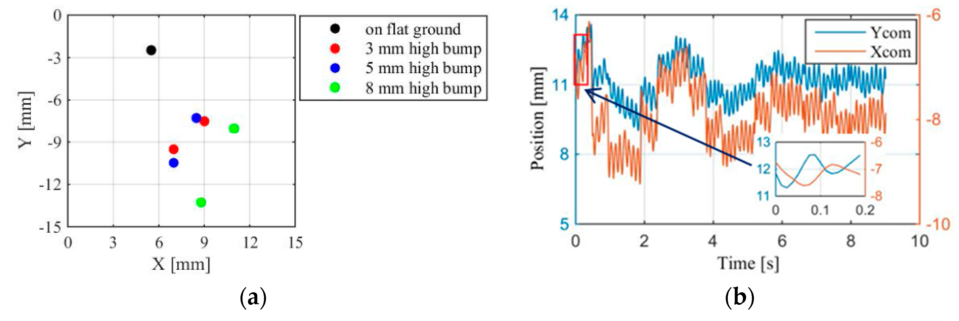
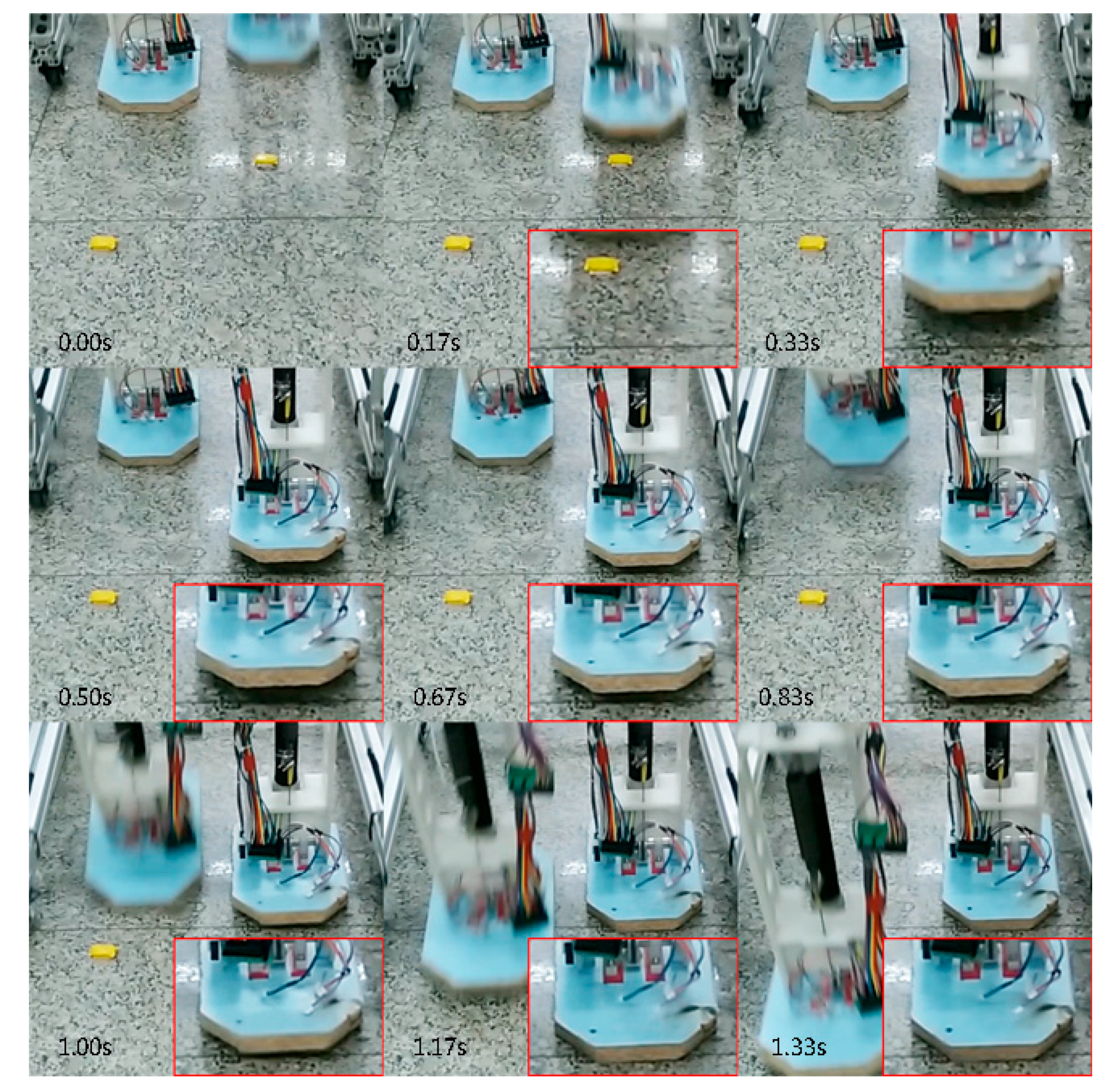
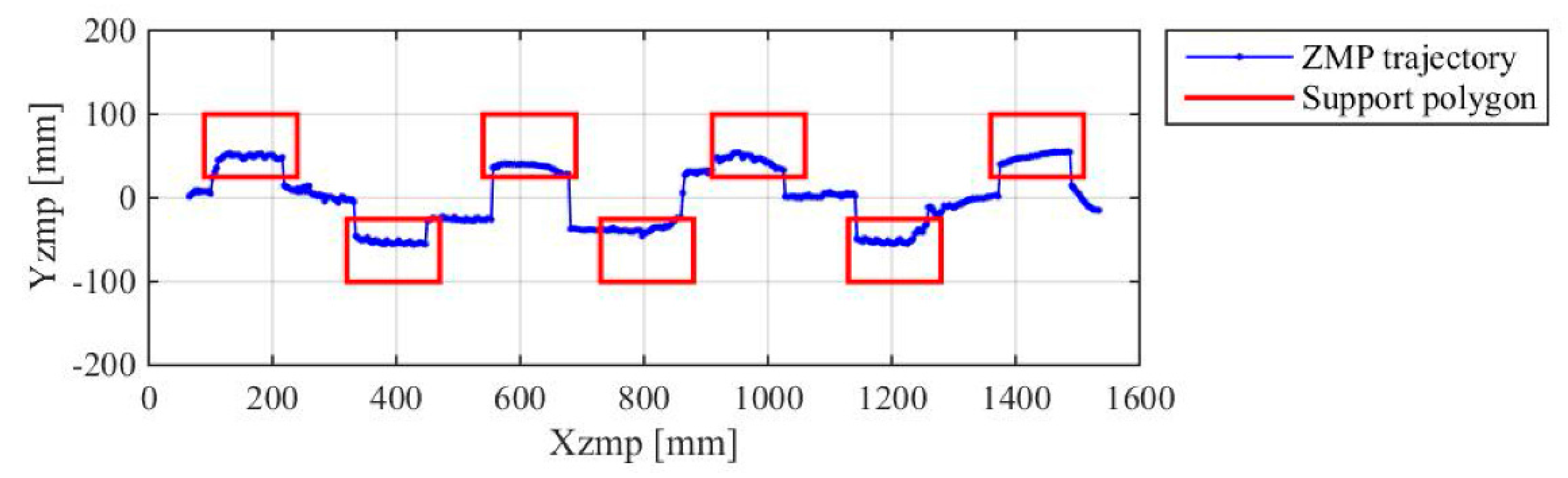
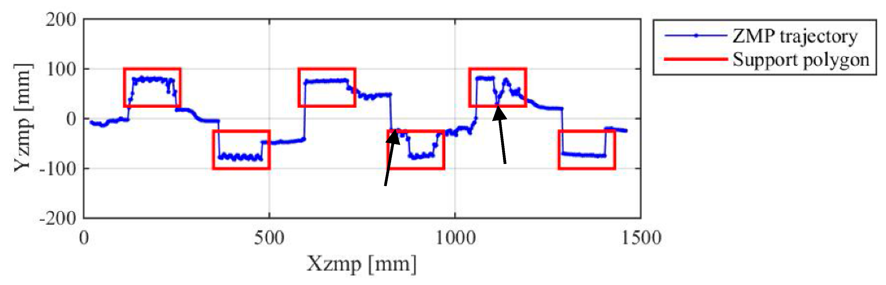
4.3. Experiment on a Biped Robot

This experiment aims to test the performance of the new foot system on a physical biped robot when the biped robot walks on the ground with small bumps. A lightweight biped robot developed by our research team is utilized in the experiment [38]. The biped robot has two three-segmented legs composed of the thigh, shank, and foot. Each leg has three planar revolute joints, namely, the hip, knee, and ankle joints. The lengths of each link from the thigh to the foot are 0.37 m, 0.36 m and 0.2 m, respectively. Their corresponding masses are 1.8 kg, 1.5 kg and 0.2 kg. The right and left legs are connected by the torso whose mass is 3 kg. The movement of the biped robot in the coronal plane is constrained by a frame presented in Figure 13, without affecting the motion in the sagittal plane [39]. For the sake of comparison, the experiment is performed with two conditions, i.e., (1) the biped robot walks with traditional flat feet; and (2) the biped robot walks with the new feet. The two kinds of feet have the same size, weight, as well as configuration of FSRs. On the ground are some small bumps promiscuously placed, of which the maximum height is 8 mm. The preplanned step length is 0.25 m, and the gait cycle is 1 s. The walking patterns are generated based on the ZMP theory. Under each condition, the biped robot is controlled to walk for ten trials and 5 m each trial. The performances of the two kinds of feet, including the behavior of the foot when contacting with the bumps and the overall walking stability, are compared.
In the case of walking with the flat feet, the contact area significantly decreased because the foot could not adapt to the bumps. Here we analyze a typical process of the foot contacting with the bumps, which was presented in Figure 14. In this figure, the images in the red panes are partially-enlarged images. During the whole phase from the foot touching the ground to the foot lifting off the ground, three contact states between the foot, ground, and bumps were shown. Firstly, after the foot stepped on the bump, only the trailing edge of the foot, rather than the whole sole, was in contact with the ground (see the upper images in Figure 14). The support polygon was a triangle encircled by the foot’s trailing edge and the contact point between the foot and bump. Secondly, as the robot walked forward, the body weight was shifted to this foot which became the new support foot. The forward movement of the CoM of the robot body caused the trailing edge of the foot off the ground. Thus, the whole robot was only supported by the bump (shown in the middle images in Figure 14). Thirdly, the robot continued swinging forward, and the leading edge of the foot touched the ground. The support polygon turned into a triangle encircled by the leading edge of the foot and the contact point between the foot and bump (see the lower images in Figure 14). These three contact states could not provide sufficient and stable support to the biped robot. Consequently, the slippage of the foot on the ground occurred frequently, and the predetermined posture of the robot was easily affected, sometimes causing the robot to fall.
On the other hand, the performance was much better in the case of walking with the new feet. The behavior of the new feet contacting with the bumps on the ground is presented in Figure 15. When the pneumatic bladders under the foot sole touched the bumps, the corresponding reversing valves were triggered successfully, and the pneumatic bladders became soft and were compressed to follow the shape of the bumps. For the pneumatic bladders which had no contact with the bumps, there were no wrong triggers occurred, and they kept high stiffness and maintained stable contact with the ground. Additionally, the bumps situated in the spaces among the pneumatic bladders did not have any effect on the foot posture. The support polygon was encircled by all the contact areas between the pneumatic bladders and the ground, which was larger than that of the flat feet. The foot slippage was avoided and stable support was provided to the biped robot.
ZMP is the most important and commonly used criterion for evaluating dynamic walking stability of biped robots. During the experiments, the actual ZMP trajectories were calculated from the measurements of FSRs equipped under the feet. The coordinate system for ZMP computation is shown in Figure 13c, of which the origin is centered at the projection of the midpoint between the two hip joints on the ground. The standard coordinate system is such that the positive x-axis points forward along the walking direction, the y-axis is to the left when looking in the x-axis direction, and the z-axis is defined upwards by the right hand rule. Figure 16 and Figure 17 present the ZMP trajectories of the biped robot under the two experimental conditions, as well as the desired support polygons in the single support phase. In the case of rigid flat feet, since the contact between the support foot and the ground was affected by the bumps, the ZMP was shifted outside the support polygon, as marked by the arrows in the figure. However, in the case of the new feet, the changes of ZMP caused by the bumps were smaller, and the ZMP trajectory in the single support phase was located inside the support polygon.
The above comparisons show that the new foot system is able to help to improve the walking performance of the biped robot when walking on the ground with small bumps. The validity of the working mechanism and mechanical structures of the foot system is further confirmed.

5. Discussion and Conclusions

In this paper, a novel variable stiffness mechanism that is able to achieve stiffness adjustment passively under the interactions with the environment is proposed. On this basis, a stiffness adjustable foot system is developed for biped robot walking on the ground with small-sized bumps. The variable stiffness mechanism, the function of the foot system, and the application of the foot system on a prototype of a biped robot are demonstrated to be feasible and effective by the results of various preliminary experiments.
However, there still exist some limitations in our research that need to be further investigated. Firstly, the mathematical model of the variable stiffness mechanism is not studied in detail in this paper, considering that it is not the current focus. However, more assistance can be provided by the accurate analytical model when determining the key design parameters, such as the stiffness of the restoring spring and supporting spring. Secondly, only simple qualitative relationships between the performance of the foot system and the major structural parameters of the PVSU are studied. The mechanical structure of the PVSU is designed by trial and error with the help of the finite element analysis method. Although the variable stiffness mechanism and the desired functions of the foot system are demonstrated to be feasible, more quantitative relationships are necessary for parameter optimization. Thirdly, the adaptability of the foot system on the bumps is somewhat limited. The experiments show that the foot is able to adapt to the bumps with a maximum height of 8 mm with quite a small change in the foot posture. Owing to the small posture change, the biped robot adopted in our research is controlled by a relatively simple controller. We think the foot may be adaptable to bumps as high as 15 mm if a larger posture change can be tolerated by the control system. Therefore, in the future, we will focus on the further improvements of the foot system.

Acknowledgments

The work reported in this paper is supported by the National Natural Science Foundation of China (grant no. 51675116). The second author is funded by the China Scholarship Council (grant no. 201606120094).

Author Contributions

Xizhe Zang, Yixiang Liu, and Wenyuan Li co-organized the work. Wenyuan Li and Zhenkun Lin carried out the experiments. Yixiang Liu wrote the manuscript draft. Jie Zhao supervised the research and commented on the manuscript draft. The manuscript was revised by all authors.

Conflicts of Interest

The authors declare no conflict of interest.

References

  1. Hirai, K. Current and future perspective of Honda humanoid robot. In Proceedings of the 1997 IEEE/RSJ International Conference on Intelligent Robots and Systems, Grenoble, France, 11 September 1997; pp. 500–508. [Google Scholar]
  2. Hirai, K.; Hirose, M.; Hikawa, Y.; Takenaka, T. The development of Honda humanoid robot. In Proceedings of the 1998 IEEE International Conference on Robotics and Automation, Leuven, Belgium, 16–20 May 1998; pp. 1321–1326. [Google Scholar]
  3. Kajita, S.; Kanehiro, F.; Kaneko, K.; Yokoi, K.; Hirukawa, H. The 3D linear inverted pendulum mode: A simple modeling for a biped walking pattern generation. In Proceedings of the 2001 IEEE/RSJ International Conference on Intelligent Robots and Systems, Maui, HI, USA, 29 October–3 November 2001; pp. 239–246. [Google Scholar]
  4. Okumura, Y.; Tawara, T.; Endo, K.; Furuta, T.; Shimizu, M. Realtime ZMP compensation for biped walking robot using adaptive inertia force control. In Proceedings of the 2003 IEEE/RSJ International Conference on Intelligent Robots and Systems, Las Vegas, NV, USA, 27–31 October 2003; pp. 335–339. [Google Scholar]
  5. Sugahara, Y.; Hosobata, T.; Mikuriya, Y.; Sunazuka, H.; Lim, H.O.; Takanishi, A. Realization of dynamic human-carrying walking by a biped locomotor. In Proceedings of the 2004 IEEE/RSJ International Conference on Robotics and Automation, New Orleans, LA, USA, 26 April–1 May 2004; pp. 3055–3060. [Google Scholar]
  6. Sakagami, Y.; Watanabe, R.; Aoyama, C.; Matsunaga, S.; Higaki, N.; Fujimura, K. The intelligent Asimo: System overview and integration. In Proceedings of the 2002 IEEE/RSJ International Conference on Intelligent Robots and Systems, Lausanne, Switzerland, 30 September–4 October 2002; pp. 2478–2483. [Google Scholar]
  7. Ogura, Y.; Aikawa, H.; Shimomura, K.; Kondo, H.; Morishima, A.; Lim, H.; Takanishi, A. Development of a new humanoid robot WABIAN-2. In Proceedings of the 2006 IEEE International Conference on Robotics and Automation, Orlando, FL, USA, 15–19 May 2006; pp. 76–81. [Google Scholar]
  8. Nugroho, S.; Prihatmanto, A.; Rohman, A. Design and implementation of kinematics model and trajectory planning for NAO humanoid robot in a tic-tac-toe board game. In Proceedings of the 2014 IEEE 4th International Conference on System Engineering and Technology, Bandung, Indonesia, 24–25 November 2014; pp. 1–7. [Google Scholar]
  9. Tsagarakis, N.; Metta, G.; Sandini, G.; Vernon, D.; Beira, R.; Becchi, F.; Righetti, L.; Santos-Victor, J.; Ijspeert, A.; Carrozza, M.; et al. iCub: The design and realization of an open humanoid platform for cognitive and neuroscience research. Adv. Robot. 2007, 21, 1151–1175. [Google Scholar] [CrossRef]
  10. Vukobratovic, M. Zero-Moment Point—Thirty five years of its life. Int. J. Humanoid Robot. 2001, 1, 157–173. [Google Scholar] [CrossRef]
  11. Braun, D.J.; Mitchell, J.E.; Goldfarb, M. Actuated dynamic walking in a seven-link biped robot. IEEE/ASME Trans. Mechatron. 2012, 17, 147–156. [Google Scholar] [CrossRef]
  12. Shin, H.; Kim, B.K. Energy-efficient gait planning and control for biped robots utilizing the allowable ZMP region. IEEE Trans. Robot. 2014, 30, 986–993. [Google Scholar] [CrossRef]
  13. Hashimoto, K.; Hosobata, T.; Sugahara, Y.; Mikuriya, Y.; Sunazuka, H.; Kawase, M.; Lim, H.; Takanishi, A. Development of foot system of biped walking robot capable of maintaining four-point contact. In Proceedings of the 2005 IEEE/RSJ International Conference on Intelligent Robots and Systems, Edmonton, AB, Canada, 2–6 August 2005; pp. 1464–1469. [Google Scholar]
  14. Wei, H.; Shuai, M.; Wang, Z. Dynamically adapt to uneven terrain walking control for humanoid robot. Chin. J. Mech. Eng. 2012, 25, 214–222. [Google Scholar] [CrossRef]
  15. Nishiwaki, K.; Chestnutt, J.; Kagami, S. Autonomous navigation of a humanoid robot over unknown rough terrain using a laser range sensor. Int. J. Robot. Res. 2012, 31, 1251–1262. [Google Scholar] [CrossRef]
  16. Stumpf, A.; Kohlbrecher, S.; Conner, D.C.; von Stryk, O. Supervised footstep planning for humanoid robots in rough terrain tasks using a black box walking controller. In Proceedings of the 2014 14th IEEE-RAS International Conference on Humanoid Robots, Madrid, Spain, 18–20 November 2014; pp. 287–294. [Google Scholar]
  17. Khadiv, M.; Moosavian, S.; Ali, A.; Yousefi-Koma, A.; Maleki, H.; Sadedel, M. Online adaptation for humanoids walking on uncertain surfaces. Proc. Inst. Mech. Eng. Part I J. Syst. Control Eng. 2017, 231, 245–258. [Google Scholar] [CrossRef]
  18. Nishiwaki, K.; Chestnutt, J.; Kagami, S. Autonomous navigation of a humanoid robot over unknown rough terrain. In Robotics Research, Springer Tracts in Advanced Robotics; Christensen, H., Khatib, O., Eds.; Springer: Cham, Switzerland, 2017; Volume 100, pp. 619–636. [Google Scholar]
  19. Lukac, D.; Siedel, T.; Benckendorff, C. Designing the test feet of the humanoid robot M-Series. In Proceedings of the XXII International Symposium on Information, Communication and Automation Technologies, Bosnia, Serbia, 29–31 October 2009; pp. 1–6. [Google Scholar]
  20. Hashimoto, K.; Sugahar, Y.; Hayash, A.; Kondo, H.; Takashima, T.; Lim, H.; Takanishi, A. Development of new biped foot mechanism mimicking human’s foot arch structure. In ROMANSY 18 Robot Design, Dynamics and Control, Proceedings of the Eighteenth CISM-IFToMM Symposium; Parenti, C.V., Schiehlen, W., Eds.; Springer: Vienna, Austria, 2010; Volume 524, pp. 249–256. [Google Scholar]
  21. Buschmann, T.; Lobmeier, S.; Ulbrich, H. Humanoid robot LOLA: Design and walking control. J. Physiol. Paris 2009, 103, 141–148. [Google Scholar] [CrossRef] [PubMed]
  22. Fondahl, K.; Kuehn, D.; Beinersdorf, F.; Bernhardy, F.; Grimminger, F.; Schillingy, M.; Starky, T.; Kirchneret, F. An adaptive sensor foot for a bipedal and quadrupedal robot. In Proceedings of the Fourth IEEE RAS/EMBS International Conference on Biomedical Robotics and Biomechatronics, Rome, Italy, 24–27 June 2012; pp. 270–275. [Google Scholar]
  23. Yamamoto, K.; Sugihara, T.; Nakamura, Y. Toe joint mechanism using parallel four-bar linkage enabling humanlike multiple support at toe pad and toe tip. In Proceedings of the 2007 IEEE International Conference on Humanoid Robots, Pittsburgh, PA, USA, 29 November–1 December 2007; pp. 410–415. [Google Scholar]
  24. Kang, H.; Hashimoto, K.; Kondo, H.; Hattori, K.; Nishikawa, K.; Hama, Y.; Lim, H.; Takanishi, A.; Suga, K.; Kato, K. Realization of biped walking on uneven terrain by new foot mechanism capable of detecting ground surface. In Proceedings of the 2010 IEEE International Conference on Robotics and Automation, Anchorage, AK, USA, 3–7 May 2010; pp. 5167–5172. [Google Scholar]
  25. Yang, H.; Shuai, M.; Qiu, Z.; Wei, H.; Zheng, Q. A novel design of flexible foot system for humanoid robot. In Proceedings of the 2008 IEEE Conference on Robotics, Automation and Mechatronics, Chengdu, China, 21–24 September 2008; pp. 824–828. [Google Scholar]
  26. Piazza, C.; Santina, C.D.; Gasparri, G.M.; Catalano, M.G.; Grioli, G.; Garabini, M.; Bicchi, A. Toward an adaptive foot for natural walking. In Proceedings of the 2016 IEEE-RAS 16th International Conference on Humanoid Robots, Cancun, Mexico, 15–17 November 2016; pp. 1204–1210. [Google Scholar]
  27. Nagarajaiah, S.; Sahasrabudhe, S. Seismic response control of smart sliding isolated buildings using variable stiffness systems: An experimental and numerical study. Earthq. Eng. Struct. Dyn. 2006, 35, 177–197. [Google Scholar] [CrossRef]
  28. Huang, Y.; Vanderborght, B.; Ham, R.V.; Wang, Q.; Damme, M.V.; Xie, G.; Lefeber, D. Step length and velocity control of a dynamic bipedal walking robot with adaptable compliant joints. IEEE/ASME Trans. Mechatron. 2013, 18, 598–611. [Google Scholar] [CrossRef]
  29. Wang, R.J.; Huang, H.P. AVSER—Active variable stiffness exoskeleton robot system: Design and application for safe active-passive elbow rehabilitation. In Proceedings of the 2012 IEEE/ASME International Conference on Advanced Intelligent Mechatronics, Kachsiung, Taiwan, 11–14 July 2012; pp. 220–225. [Google Scholar]
  30. Wu, Y.S.; Lan, C.C. Design of a linear variable-stiffness mechanism using preloaded bistable beams. In Proceedings of the 2014 IEEE/ASME International Conference on Advanced Intelligent Mechatronics, Besacon, France, 8–11 July 2014; pp. 605–610. [Google Scholar]
  31. Kuder, I.K.; Arrieta, A.F.; Raither, W.E.; Ermanni, P. Variable stiffness material and structural concepts for morphing applications. Prog. Aerosp. Sci. 2013, 63, 33–55. [Google Scholar] [CrossRef]
  32. Kind, R.J. Pneumatic stiffness and damping in air-supported structures. J. Wind Eng. Ind. Aerodyn. 1984, 17, 295–304. [Google Scholar] [CrossRef]
  33. Pan, P.; Liao, G.; Yan, G.; Zhao, Y. Calculation of elastic deformation for the sealing gasket. J. Harbin Inst. Technol. 1996, 28, 130–134. [Google Scholar]
  34. Liu, H.; Lee, J.C. Model development and experimental research on an air spring with auxiliary reservoir. Int. J. Automot. Technol. 2011, 12, 839–847. [Google Scholar] [CrossRef]
  35. Wickramatunge, K.C.; Leephakpreeda, T. Empirical modeling of dynamic behaviors of pneumatic artificial muscle actuators. ISA Trans. 2013, 52, 825–834. [Google Scholar] [CrossRef] [PubMed]
  36. Chou, C.P.; Hannaford, B. Static and dynamic characteristics of McKibben pneumatic artificial muscles. In Proceedings of the 1994 IEEE International Conference on Robotics and Automation, San Diego, CA, USA, 8–13 May 1994; pp. 281–286. [Google Scholar]
  37. Carbone, G. Stiffness analysis and experimental validation of robotic systems. Front. Mech. Eng. 2011, 6, 182–196. [Google Scholar]
  38. Liu, Y.; Zang, X.; Liu, X.; Wang, L. Design of a biped robot actuated by pneumatic artificial muscles. Bio-Med. Mater. Eng. 2015, 26, 757–766. [Google Scholar] [CrossRef] [PubMed]
  39. Klein, T.; Lewis, M.A. A neurorobotic model of bipedal locomotion based on principles of human neuromuscular architecture. In Proceedings of the 2012 IEEE International Conference on Robotics and Automation, Saint Paul, MN, USA, 14–18 May 2012; pp. 1450–1455. [Google Scholar]
Figure 1. Schematic diagram of the stiffness adjustable foot system.
Applsci 07 01005 g001
Figure 2. Comparisons between a conventional rigid flat foot and the new foot on the ground with various bumps and obstacles.
Applsci 07 01005 g002
Figure 3. Working principle diagram of the pneumatic variable stiffness unit (PVSU).
Applsci 07 01005 g003
Figure 4. The system stiffness of the PVSU in the entire compression process.
Applsci 07 01005 g004
Figure 5. The main structure parameters of the pneumatic bladder.
Applsci 07 01005 g005
Figure 6. Simulated stiffness of the pneumatic bladder under different combinations of material hardness and wall thickness.
Applsci 07 01005 g006
Figure 7. The PVSU. (a) The sectional view of the PVSU; (b) the prototype of the PVSU; and (c) the molds developed for the pneumatic bladder.
Applsci 07 01005 g007
Figure 8. The prototype of the stiffness-adjustable foot system.
Applsci 07 01005 g008
Figure 9. Schematic diagram of the experimental apparatus.
Applsci 07 01005 g009
Figure 10. Measured force-compression curves of the PVSU.
Applsci 07 01005 g010
Figure 11. The experiment on the foot system. (a) The overall experimental apparatus; (b) the foot on a 3-mm high bump; (c) the foot on a 5-mm high bump; and (d) the foot on an 8-mm high bump.
Applsci 07 01005 g011
Figure 12. Results of experiment on the foot system. (a) The stable values of CoM projections under different experimental conditions; and (b) the CoM positions in the X and Y axis versus time.
Applsci 07 01005 g012
Figure 13. Experimental apparatus of the biped robot. (a) Prototype of the biped robot; (b) schematic diagram of the biped robot; and (c) the coordinate system of the biped robot for ZMP computation.
Applsci 07 01005 g013
Figure 14. Screenshots of the flat foot contacting with the bumps on the ground during walking.
Applsci 07 01005 g014
Figure 15. Screenshots of the new foot contacting with the bumps on the ground during walking.
Applsci 07 01005 g015
Figure 16. ZMP trajectory of the biped robot in the case of walking with the rigid flat feet.
Applsci 07 01005 g016
Figure 17. ZMP trajectory of the biped robot in the case of walking with the new feet.
Applsci 07 01005 g017

