Effect of Steel Fiber and Different Environments on Flexural Behavior of Reinforced Concrete Beams
by
Mohammad Ali Barkhordari Bafghi
1, 
Fereydon Amini
1,*, 
Hamed Safaye Nikoo
1 and
Hamed Sarkardeh
2 1
School of Civil Engineering, Iran University of Science and Technology, Tehran 98021, Iran
2
Department of Civil Engineering, School of Engineering, Hakim Sabzevari University, Sabzevar 980571, Iran
*
Author to whom correspondence should be addressed.
Appl. Sci. 2017, 7(10), 1011; https://doi.org/10.3390/app7101011
Submission received: 14 August 2017
/
Revised: 16 September 2017
/
Accepted: 26 September 2017
/
Published: 30 September 2017
Abstract
:The main kind of deterioration in marine Reinforced Concrete (RC) structures and other infrastructures is steel bar corrosion due to cracks in concrete surfaces, which leads to the reduction of the load carrying capacity, ductility, and structural safety. It seems that steel fibers can reduce and delay the cracking, and increase the flexural strength and ductility of marine RC structures. To do so, in marine atmosphere and the tidal zone of the Oman Sea and fresh water, the flexural behavior of beams containing Plain Concrete (PC), Concrete with Steel fiber Reinforcement (SFRC), RC, Concrete with Steel fiber, and bar Reinforcement ((R+S)C) at 28, 90 and 180 days were determined. Beams were 99 un-cracked and pre-cracked beams, with dimensions of 200 × 200 × 750 mm. Based on results and at 180 days, the flexural strength and toughness of pre-cracked (R+S)C beams were 22–43% higher than the pre-cracked RC beams. The effect of steel fiber on the increment of load capacity and the toughness of pre-cracked RC beams were approximately the same. By addition of steel fiber to un-cracked RC beams, load capacity and toughness were increased up to 20%. The load capacity and toughness in marine atmosphere and tidal zone were approximately 15% lower than the fresh water condition.
1. Introduction
One of the most important subjects for engineers is consideration of the strength and durability of marine concrete structures [1]. In term of durability, parts of structure that are placed in the marine atmosphere and tidal zone are subjected to aggressive agents and the worst deterioration. The main kind of deterioration in marine RC structures is steel bar corrosion due to chloride ion penetration. During the service life of marine structures, concrete cracking can facilitate the chloride penetration and increase the steel bar corrosion [2]. To reduce the concrete cracking, fibers can delay the start and growth of the cracks. Fibers can decrease the crack width and increase the Flexural Strength (fr) and Toughness (T) [3,4].
Among the fibers, steel fibers, by an excellent bonding performance with the surrounding cementitious matrix, can effectively improve the flexural strength and toughness of Reinforced Concrete (RC) beams [5]. However, the role of steel fiber can be affected by the environmental conditions. In a marine environment, the addition of steel fibers to the RC beams may have no positive effect on toughness due to the probable corrosion of steel fibers. Consequently, before the study of steel fibers’ role in the flexural behavior of RC beams in a marine environment, the durability of SFRC should be reviewed. Moreover, the effect of steel fiber on the corrosion of bar in an aggressive environment should be studied.
1.1. Durability of SFRC
In terms of SFRC durability, Kim et al. [6] investigated that the addition of fiber to concrete has no effect on its resistance to carbonation. The highest average residual strength and toughness was related to the addition of hooked-end steel fibers as compared with polypropylene and polyvinyl alcohol fibers. Vaishali and Rao [7] showed that use of steel, glass, and polypropylene fibers reduces the concrete chloride ion permeability by about 42%, 36% and 40%, respectively, and chloride ion permeability of specimens containing steel fibers is less than polypropylene and glass fibers. Anandan et al. [8] found that until 180 days, by addition of steel fibers to concrete, fr in alternate wetting and drying cycles increases 8% to 18%. The fr of specimens, which were cured in salt solution, was increased 8–15%. Abbas et al. [9] found that after chloride ions exposure, steel fibers on the surface of SFRC specimens are corroded up to a specified depth (3 mm), and there is no evidence of corroded fibers at a higher depth. They investigated that fiber length has not important effect on the durability properties of specimens, but a higher volume of fiber improves the durability properties.
1.2. Comparison of Steel Bar and Steel Fiber Corrosion
In terms of steel bar and fiber corrosion in concrete, Janotka et al. [10] resulted that while the bar shows corrosion at 2% calcium chloride, the fibers do not indicate any harmful corrosion until the chloride content is 6%. They investigated that the addition of chloride to concrete can be less harmful in SFRC rather than RC. Granju and Balouch [11] showed that in the case of SFRC, fiber corrosion is less active than a steel bar. They found that the crack-bridging capacity of the fiber in specimens that are placed in a marine-like environment is increased by corrosion. Sadeghi-Pouya et al. and Mihashi et al. [12,13] investigated that steel fibers in cylinder specimens show less damage than the normal bar in these samples. Moreover, the Flexural performance of specimens with corroded steel fiber is not decreased by corrosion attack. Söylev and Özturan [14] found that the corrosion rate of the bar in concrete reinforced with glass and polypropylene fibers is higher than SFRC in cylinder specimens.
1.3. Effect of Steel Fiber on Strength and Toughness of RC Beams in Laboratory Condition
In term of effect of steel fiber on fr(RC) and T(RC), Bentur and Mindesst [15] found that by the addition of steel fibers, the fr(RC) is increased 32–55%. Ahad and Aziz [16] investigated that steel fiber increases the maximum load capacity (Pmax) of RC T-beams (5–12%). Vandewalle [17] found that by the addition of steel fiber to the RC beam, the mean value of crack width and spacing are decreased 37% and 20%, respectively. Campione and Mendola and Meda et al. [18,19] found that steel fibers could increase the TRC by useful effects on increasing the bar-to-concrete bond. Mertol et al. [20] investigated that T(R+S)C is greater than TRC. They found that by increasing the reinforcement ratio by over 1.6%, T(R+S)C becomes significantly more than TRC. Therefore, the effect of steel fiber in increment of strength and ductility of RC beams in laboratory and standard condition is considerable.
According to previous studies, the durability of marine RC structures and the improvement of their flexural behavior is very important. Moreover, the positive role of steel fibers in the prevention of crack growth and increasing the flexural toughness of RC beams is considerable. However, it seems that the role of steel fiber is dependent on environmental conditions. Despite much research on the flexural parameters of SFRC and RC, no comprehensive study was performed on the effect of different environments on flexural behavior of (R+S)C beams. To do so, in the present study, by measuring the values from Load-Deflections diagrams, flexural properties of (R+S)C beams, such as maximum load capacity (Pmax(R+S)C), flexural toughness (T(R+S)C), and Service Stiffness (S.S) of (R+S)C beams in marine atmosphere, tidal zone, and fresh water were investigated and analyzed. Experiments were performed on about 100 concrete beams with dimensions of 200 × 200 × 750 mm, in two modes of un-cracked and pre-cracked beams.
2. Materials and Methods
2.1. Material Properties
Ordinary Portland cement Type II was used in the present study. Silica fume, Super-Plasticizer (SP), and coarse aggregate, with a maximum size 19 mm were used. Silica fume as a cement replacement was added by 10% of weight to cementitious materials and the water to cement ratio was 0.4. Steel fibers had 50 mm length, 0.8 mm diameter, 0.5% volume fraction, and a density of 7.80 (kg/m3). Concrete mix proportions are provided in Table 1. The average of compressive strength of PC and SFRC specimens at 28 days was approximately the same (30 MPa). For compressive strength, cylindrical specimens with a diameter of 150 mm and a length of 300 mm were fabricated and tested.
In Table 1 the beams could be divided into four series: Plain Concrete (PC), RC, Concrete with Steel fiber Reinforcement (SFRC), and (R+S)C.
2.2. Specimens Test
Figure 1 shows the detail of (R+S)C beams.
All of the specimens were 200 × 200 × 750 mm with a rectangular cross section. Four-point loading was applied, producing a constant moment region of 210 mm in the middle of 650 mm clear span. Four-point loading was monotonically applied with a maximum capacity 1000 kN and the loads and deflections were simultaneously recorded. The recording rate for mid-span deflections and the load was 1 mm/min. In order to obtain the net mid-span deflection, the support settlements were subtracted from the measured mid-span deflection by using Linear Variable Differential Transformers (LVDTs). At each loading stage, the number of cracks and average crack spacing was recorded by taking the film.
The longitudinal bar size was 10 mm. The reinforcement ratio was about 0.6%. Transverse reinforcements in the form of 6 mm diameter by spacing at 65 mm were used. The cover thickness for longitudinal and transverse reinforcement was 55 mm. The longitudinal and transverse reinforcements had a nominal yield strength of 400 MPa.
The main variables were three environments, un-cracked or pre-cracked, steel fiber, and bar. Three environments were Marine Atmospheric (MA), and marine Tidal zone (Ti) and laboratory condition (a tank of fresh Water (W)). Beams were divided to Pre-cracked (Pr) and Un-cracked (Un). Table 2 shows the details of the beams and environments. For example, in Table 2 the mixture (R+S)C (Ti-Un) shows the un-cracked (R+S)C beams in the marine tidal zone.
2.3. Methods
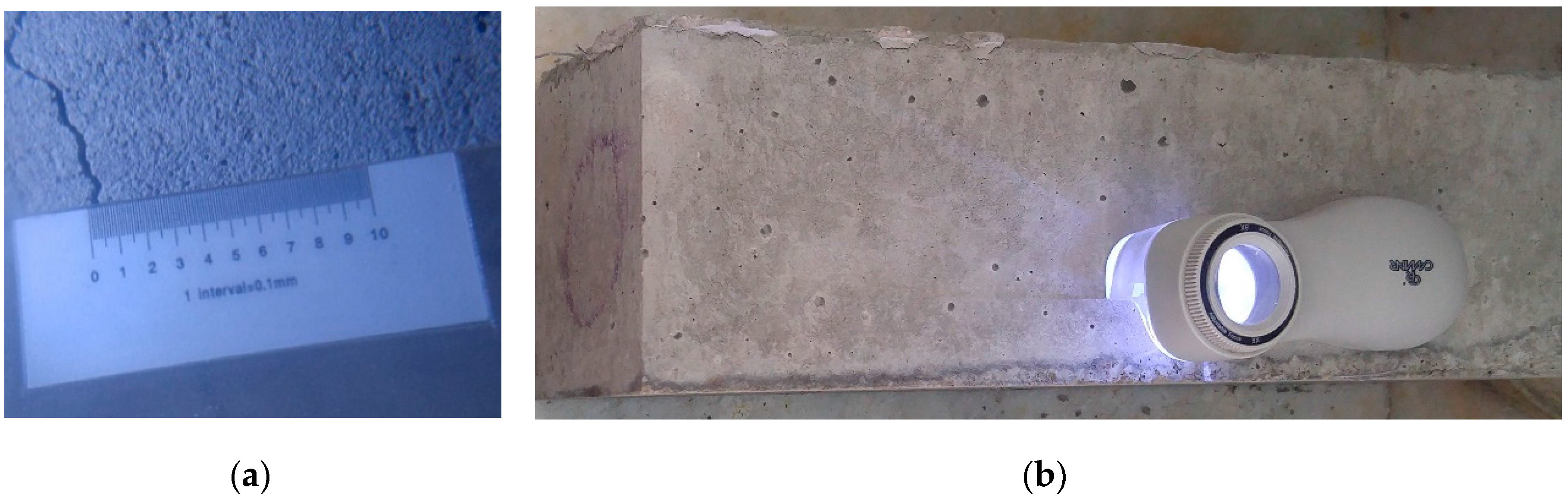
The fresh concrete was cast in 200 × 200 × 750 mm beam specimens. At least three beams were cast for each mix. Twenty-four hours after demolding, for simulating the real condition of cracking in marine structures, the beams that should be cracked, were loaded under four-point loading to induce cracks of 0.35 mm widths. Because of the reduction of crack width after un-loading, cracking continued until approximately 0.5 mm width (empirically and based on a test of different beams). The crack widths were measured on the tension face by means graduated magnifier (Figure 2).
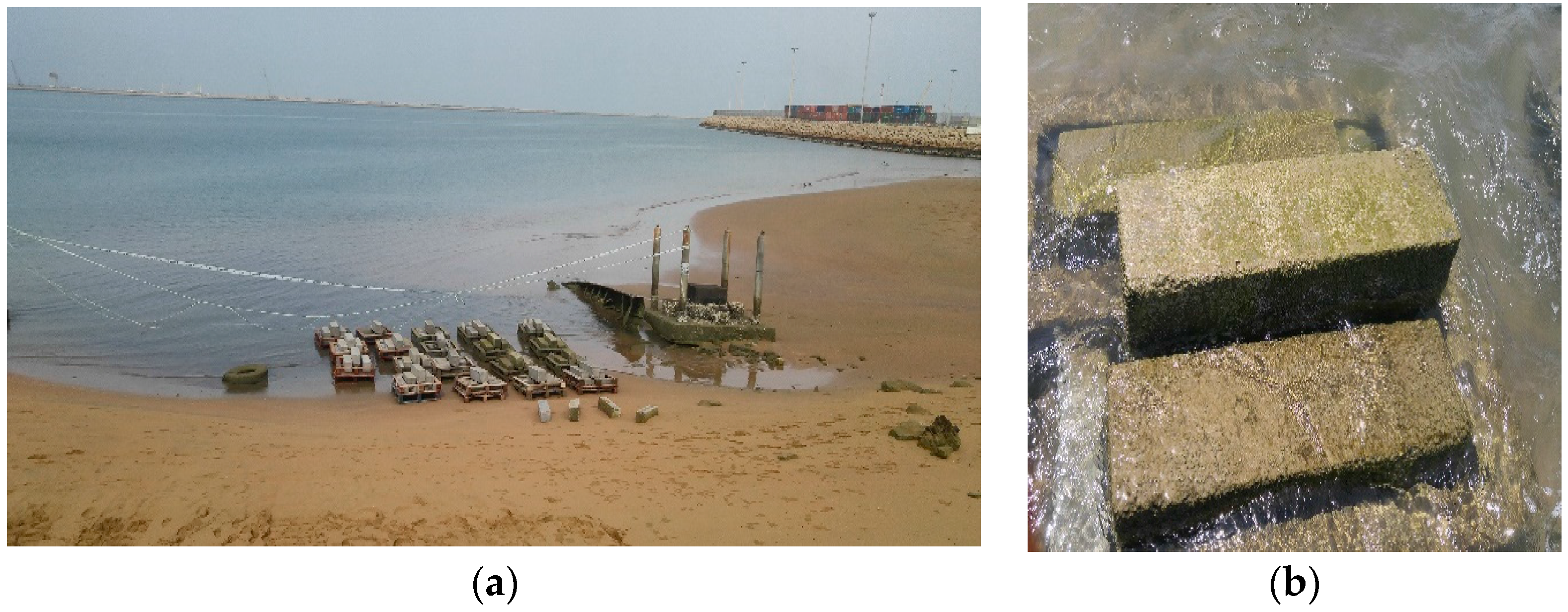
Then the beams were carried to the marine atmosphere and tidal zone of the Oman Sea and fresh water. Beams condition in the Oman Sea is shown in Figure 3.
The temperature in the Oman Sea was 20–25 °C and the pH value was 7.56. The measured values were Load and Deflections, and the calculated parameters were Pmax, fr, T and S.S at 28, 90 and 180 days.
3. Discussion of Results
Considering the achieved load-deflection diagram (Figure 4, Figure 5 and Figure 6), the calculated parameters were Pmax, fr, T, and S.S of PC, SFRC, RC, and (R+S)C beams in marine atmosphere, tidal zone, and fresh water (according to Table 4 and Table 5). In term of fr, T and S.S definitions:
As can be known, fr as a flexural strength is calculated from Pmax (Equation (1)) [22]:
where L is span length (650 mm), b is the average width (200 mm), and h is the average depth of the beam (200 mm). The T is a measure of the energy absorption capacity of the beam, which is calculated by the area of the load-deflection diagram up to a specific point, such as maximum deflection [23]. A comparison of the T cannot be easily carried out for beams with fiber and bar, as it is quite difficult to identify a maximum deflection. However, in this study for calculating the T, maximum deflection was selected 15 mm for all of the beams. S.S values were determined as the slope of the load-deflection diagram following the initiation of flexural cracking, and were obtained by calculating the line slope between the two points corresponding to 50% and 80% of the Pmax on the ascending branch of the load–deflection diagram [20].
fr = PmaxL/bh2
After the determination of result data and plot of diagrams for each mixture series, the trend of diagrams was determined and drawn. Scatter of the diagrams was generally related to small changes in temperature and the humidity condition at the time of making the concrete and error in the sensitivity of machine sensors in the record of the diagram. The average flexural load–deflection diagram was shown in Figure 4, Figure 5 and Figure 6. In following sections, by measured values from Load-Deflections diagram effect of steel fibers on Pmax, fr, T and S.S of PC and RC beams (un-cracked and pre-cracked) in marine atmosphere, tidal zone, and fresh water will be studied.
3.1. Flexural Strength and Toughness of Pre-Cracked (R+S)C Beams in Water and Marine Atmosphere Condition
Figure 4 shows the load-vertical deflection diagrams for pre-cracked RC and (R+S)C beams at 28, 90 and 180 days in fresh water and marine atmosphere condition.
In the water conditions, Pmax(Pr-RC)28 and T(Pr-RC)28 by addition of steel fibers were decreased about 16%. However, Pmax(Pr-(R+S)C)180 and T(Pr-(R+S)C)180 were 22% higher than Pmax(Pr-RC)180 and T(Pr-RC)180. Consequently, with an increasing of age, the role of steel fiber in arresting the cracks will be significant. In water condition, up to 180 days, the effect of steel fiber on increment of T(Pr-RC) and Pmax(Pr-RC) was approximately the same. By the addition of steel fiber to the pre-cracked RC beam in water environment, the S.S(Pr-RC)28 was decreased by about 37%. However, at 180 days, the S.S(Pr-(R+S)C)180 was 38% higher than S.S(Pr-RC)180. Because of the cracking limitation, as well as delay in the growing of cracks, the role of steel fiber in S.S(Pr-RC) at 180 days will be increased. The main reason for decreasing the T(Pr-RC) and Pmax(Pr-RC) by addition of steel fiber at 28 days may be related to a higher porosity in concrete in primary ages. Increasing T(Pr-RC) and Pmax(Pr-RC) at 180 days in water environment may be due to the effect of steel fibers in increasing the bar-to-concrete bond and bridging faces of cracks [19,24]. Generally, the use of steel fibers in concrete can be efficient in the limitation of cracks at both micro and macro dimensions. At the micro-level, steel fibers prevent the beginning and development of cracks, and after the micro-cracks link with together and change to macro-cracks, steel fibers prepare mechanisms that provide effective bridging and reduce the rate of crack growth, finally enhancing the toughness and ductility [3,4].
By addition of steel fiber to pre-cracked RC beams in the marine atmosphere environment, the Pmax(Pr-RC)28 and T(Pr-RC)28 were decreased 9% and 7%, respectively. With increasing the age, Pmax(Pr-(R+S)C)180 and T(Pr-(R+S)C)180 were approximately 27% higher than Pmax(Pr-RC)180 and T(Pr-RC)180. Thus, in marine atmosphere environment like to water condition, the steel fiber role in limitation of crack width at 180 days was bolded. According to the Figure 4, at 28 days, the amount of Pmax(Pr-(R+S)C)28 and T(Pr-(R+S)C)28 in the water and marine atmosphere condition did not have noticeable differences, while at 180 days, the role of marine atmosphere environment in decrease of Pmax(Pr-(R+S)C)28 and T(Pr-(R+S)C)28 will be bolded. In a marine atmosphere environment of up to 180 days, the effect of steel fiber on the growth of Pmax(Pr-RC) and T(Pr-RC) was approximately the same. By addition of steel fiber to the pre-cracked RC beam, the S.S(Pr-RC)28 was decreased by about 6%. However, at 180 days, the S.S(Pr-(R+S)C)180 was 43% higher than S.S(Pr-RC)180.
The reason for the decrease of Pmax(Pr-RC) and T(Pr-RC) at 28 days by the addition of steel fibers in the marine atmosphere region may be due to an increase in the concrete porosity by steel fiber and a lack of concrete self-healing in early ages. Moreover, a serious deficiency may exist in the transition zone of FRC. Especially in the earlier ages, there is a thick and weak transition zone with a lot of porosity between steel fibers and the paste, which can lead to a decrease in the flexural capacity [25].
However, with increasing the age, decreasing the porosity, and consolidating the transition zone, the role of steel fibers on the enhancement of Pmax(Pr-RC) and T(Pr-RC) will be increased. Moreover, the appearance of light corrosion at the surface of the steel fibers leads to an enhancement of their bond and further friction with the cementitious matrix, and finally, Pmax(Pr-RC) and T(Pr-RC) will be increased. Since the formation of cracks in concrete was delayed by the addition of steel fiber [26], an increment of S.S by the addition of steel fiber to the pre-cracked RC beams would be justified. According to Figure 4, at the beginning of the diagram, the slope of diagram for pre-cracked (R+S)C beams was higher than pre-cracked RC beams. It may be due to the increase of rigidity by steel fibers by arresting the cracks and reducing the deflection.
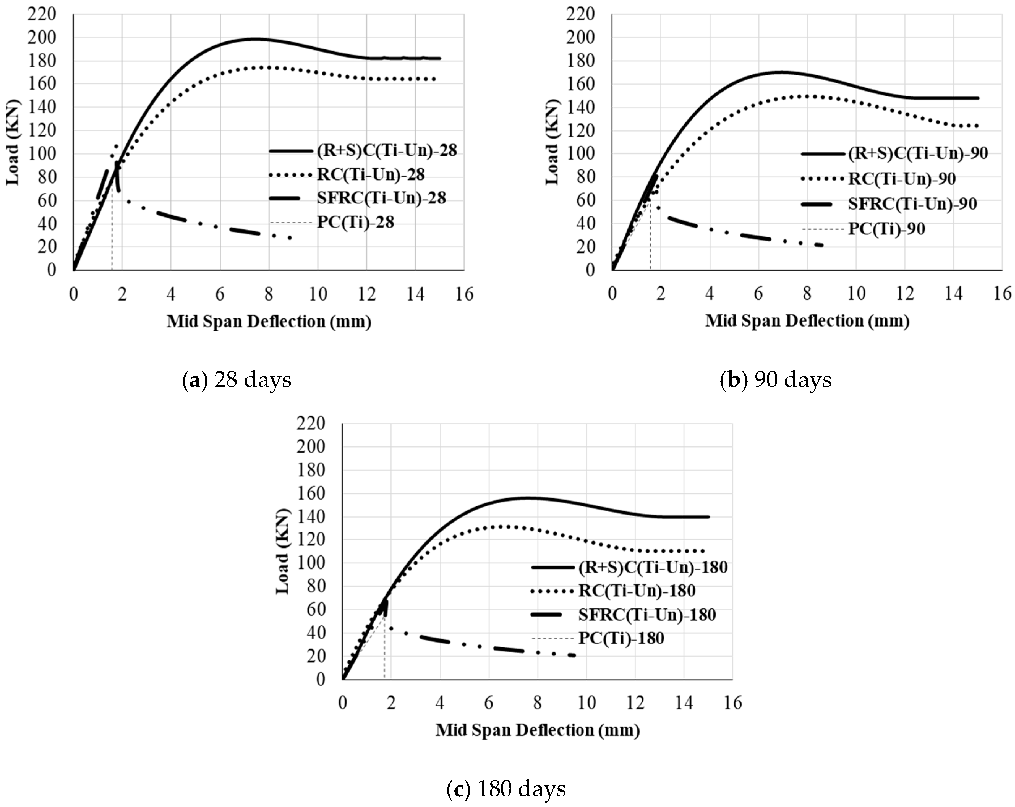
3.2. Flexural Strength and Toughness of Un-Cracked Beams in Marine Tidal Zone
Figure 5 shows the load-vertical deflection diagrams for un-cracked beams in tidal zone at 28, 90 and 180 days.
In tidal zone, by the addition of steel fibers to the PC beams, Pmax(PC)28 and T(PC)28 was increased 46% and 586%, respectively. It was cleared that the role of steel fibers in increasing the T(PC) is higher than the Pmax(PC). The slope of PC and SFRC diagram at the beginning was approximately the same. It can be due to the more important role of steel fiber after cracking rather than before concrete cracking. By addition of steel fibers to the un-cracked RC beams in the tidal zone environment, the Pmax(Un-RC)28 and T(Un-RC)28 were increased 14% and 12%, respectively. It was cleared that the slope of un-cracked (R+S)C and un-cracked RC diagrams is approximately the same. Moreover, by addition of steel fiber to the un-cracked RC beams, the S.S(Un-RC)28 is increased by about 27%. In the tidal zone at 90 days, Pmax(Un-SFRC)90 was 34% higher than Pmax(PC)90. T(Un-SFRC)90 was also 516% higher than T(PC)90. Meanwhile, Pmax(Un-(R+S)C)90 and T(Un-(R+S)C)90, were about 14% higher than Pmax(Un-RC)90 and T(Un-RC)28. Moreover, S.S(Un-(R+S)C)90 was 35% higher than S.S(Un-RC)90.
At 180 days, by addition of steel fibers to the PC beams, Pmax(PC)180 was increased 24% while the T(PC)180 was increased 514%. It was cleared that the main role of steel fibers in increasing the T(PC) is higher than the Pmax(PC). The slope of PC and SFRC diagram at the beginning was approximately the same. It may be due to the more important role of steel fiber after cracking, rather than before concrete cracking. At 180 days, in tidal zone environment, the Pmax(Un-RC)180 and T(Un-RC)180 was increased by about 19%. Thus, the positive role of steel fibers in increasing the Pmax(Un-RC) and T(Un-RC) was approximately the same. It was cleared that the slope of diagram related to un-cracked (R+S)C and RC beams, is approximately equaled. Moreover, By the addition of steel fiber to the un-cracked RC beams, the S.S(Un-RC)180 was increased by about 16%.
Steel fibers could increase the rigidity by arresting the crack and reducing the crack growth. Generally, in SFRC, The corrosion may act in different manners, with the following different effects: [11] (a) if the fibers strength is reduced noticeably by the corrosion, Pmax will be decreased, with an embrittlement behavior after Pmax; (b) if the crack self-healing happens during marine condition, Pmax will be increased due to concrete continuity through the crack. Moreover, the post-peak behavior is expected to rejoin one of the non-corroded beams; and, (c) if the crack healing does not happen, corrosion of the fibers lead to an increase in their friction in the cement matrix. According to mechanisms (a) to (c), the reason for increasing the Pmax and T may be due to the corrosion of steel fibers surface and concrete self-healing.
Because of the following reason, the corrosion of steel fibers up to 180 days cannot lead to a decrease of Pmax: (1) the expansive forces from corrosion of steel fibers are not enough for the concrete detachment because of the little diameter of fibers and the little volume created by the oxides. Consequently, the corrosive process is not sufficient to split the concrete [27]; (2) if the crack width is thinner than about 0.1 mm than the steel fiber will not corrode. If the cracks width is ranged between 0.1 mm to 0.5 mm, a little corrosion of the steel fibers with no decrease of their section happens. Only in steel fibers crossing the crack within a 2–3 mm rim from the external faces of the beams, the wide corrosion is observed [11]. According to the reasons (1) and (2), corrosion of steel fiber and the loss of its strength is difficult. However, maybe the formation of light corrosion on the surface of steel fiber leads to an increase of the friction in the cement matrix-fiber interface and growth of Pmax and T.
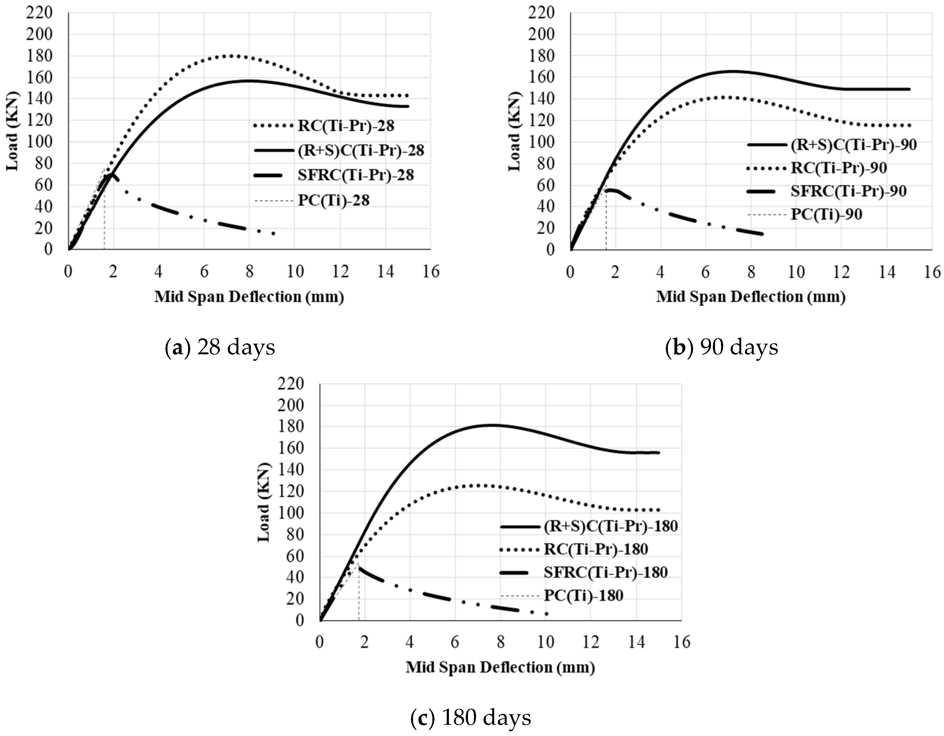
3.3. Flexural Strength and Toughness of Pre-Cracked Beams in Marine Tidal Zone
Figure 6 shows the load-vertical deflection diagrams for pre-cracked SFRC, RC, (R+S)C, and PC beams in the tidal zone at 28, 90 and 180 days.
It was found that the Pmax(PC)28 is approximately 6% higher than Pmax(Pr-SFRC)28 in the tidal zone. However, the T(Pr-SFRC)28 was 441% higher than T(PC)28. It may be related to the more important role of steel fiber in T rather than the Pmax. By addition of steel fiber to pre-cracked RC beams, the Pmax(Pr-RC)28 and T(Pr-RC)28 were decreased 13% and 11%, respectively. It may be due to a higher porosity of concrete in pre-cracked (R+S)C beams rather than pre-cracked RC beams at 28 days. The effect of steel fiber on the decrease of Pmax(Pr-RC)28 and T(Pr-RC)28, was approximately the same. Moreover, by the addition of steel fiber to the pre-cracked RC beams, S.S(Pr-RC)28 was decreased by about 11%. Pmax(Pr-SFRC)90 was 8% lower than Pmax(PC)90, T(Pr-SFRC)90 was 482% higher than T(PC)90. Pmax(Pr-(R+S)C)90, and T(Pr-(R+S)C)90, were about 17% higher than Pmax(Pr-RC)90 and T(Pr-RC)90. The S.S(Pr-(R+S)C)90 is 16% more than S.S(Pr-RC)90.
At 180 days, it was cleared that the Pmax(PC)180 is approximately 7% higher than Pmax(Pr-SFRC)180 in the tidal environment. However, the T(Pr-SFRC)180 was 387% higher than T(PC)180. It may be due to the bolded role of steel fiber in T rather than Pmax. By addition of steel fiber to pre-cracked RC beams, Pmax(Pr-RC)180 and T(Pr-RC)180 were increased by about 43%. Reduction of steel bar corrosion in pre-cracked (R+S)C beams and an increase of Pmax(Pr-R)C and T(Pr-R)C, (Pr-RC) may be due to three reasons: (1) the cracks width in (R+S)C beams is lower than the RC beams due to the bridging of cracks by the steel fibers and the higher fracture resistance of (R+S)C beams; (2) based on observation analysis, the formation of self-healing products in some of the cracks in the SFRC beam is considerable; and, (3) anodic and cathodic region are formed in steel bars when the corrosion of the steel bar will happen in pre-cracked RC beams. In the case of (R+S)C beams, steel fibers are distributed randomly. Consequently, it is possible to touch the steel bar and fiber and interconnect in the cover zone. Due to their connectivity, the anodic region is extended from the steel bar to steel fibers. Hence, the steel fibers play the role of the sacrificial anodic zone and the corrosion in the cathodic region continues until the availability of hydroxyl ions. Thus, steel fiber will be corroded before the steel bar and the corrosion of steel bar will be reduced or stopped. The rest of the steel fibers that is disconnected to the steel bar will be preserved by the concrete alkalinity [13]. Therefore, in pre-cracked (R+S)C beams, bonding between bar and cement past will be higher than the pre-cracked RC beams. Consequently, Pmax(Pr-(R+S)C) and T(Pr-(R+S)C) will be higher than Pmax(Pr-RC) and T(Pr-RC).
It was indicated that by addition of steel fiber to the pre-cracked RC beams, S.S(Pr-RC)180 is increased by 42%. It may be because of the steel fiber role in the limitation of cracking and reducing the growth of cracks, as well as the decreasing of porosity in higher ages. At the beginning of the diagram, the slope of diagram for pre-cracked (R+S)C beams in tidal zone was higher than pre-cracked RC beam at 180 days. It indicated that the higher rigidity of pre-cracked (R+S)C beams rather than pre-cracked RC ones. It was cleared that in the presence of steel fibers, there is not noticeable difference between the Pmax(Pr-(R+S)C)28 with Pmax(Pr-RC)28 or T(Pr-(R+S)C)28 with T(Pr-RC)28 in three environments (the marine atmospheric, tidal zone, and fresh water condition). However, with increasing the specimens age, Pmax(Pr-(R+S)C) and T(Pr-(R+S)C) in marine atmosphere and tidal zone were decreased approximately 11% to 14% rather than fresh water condition. As can be expected, the decrease of Pmax and T in the tidal zone will be higher than the marine atmosphere environment. Deterioration of concrete in marine structures can be occurred in three zones: (1) submerged zone; (2) tidal zone; and, (3) atmospheric zone. Usually, RC elements that are placed in the submerged zone are exposed to chemical reactions and a little corrosion. RC elements, which are situated in the tidal zone, are exposed to freezing and thawing, physical actions, corrosion, chemical reactions, and erosion. RC elements, which are placed in the marine atmosphere zone, are exposed to the corrosion and chemical reactions. Therefore, it is expected that the deterioration in RC elements that are exposed to the tidal zone is higher than the other location [28].
4. Conclusions
In the present study, by examining about 100 beams with dimensions of 200 × 200 × 750 mm, the effect of steel fiber and different environments on the flexural behavior of RC beams was investigated. Environments were fresh water, Oman sea atmosphere, and tidal zone. Beams were pre-cracked and un-cracked. The ages were 28, 90, and 180 days. The measured values were Load and Deflections, and the calculated parameters were Pmax, fr, T and S.S.
In water and marine atmosphere condition:
By addition of steel fiber, in 28 days, Pmax(Pr-RC), T(Pr-RC), and S.S(Pr-RC) 6–37% were decreased, and in 180 days, Pmax(Pr-RC), T(Pr-RC) and S.S(Pr-RC) 22–43% were increased. In 180 days, the role of steel fibers on toughness and load capacity of RC beams was important.
In tidal zone:
By the addition of steel fibers to the PC beams, Pmax(PC) and T(PC) was increased. It was cleared that the main role of steel fibers in increasing the T(PC) was higher than the Pmax(PC). The toughness of pre-cracked SFRC was approximately five times the toughness of PC beams. Load capacity and toughness of pre-cracked (R+S)C beams were 43% higher than the pre-cracked RC beams. By addition of steel fiber to un-cracked RC beams, the load capacity and toughness were increased by up to 20%.
In water condition, marine atmosphere and tidal zone:
The effect of steel fiber on the increment of T(RC) and Pmax(RC) was approximately the same. In 28 days, the amount of Pmax(Pr-(R+S)C) and T(Pr-(R+S)C) in three environments were approximately equalled. At 180 days, Pmax(Pr-(R+S)C) and T(Pr-(R+S)C) in marine atmosphere and tidal zone were up to 15% lower than fresh water condition.
Acknowledgments
This work was supported by the research grant of the Chabahar Maritime University in 2017.
Author Contributions
Hamed Sarkardeh and Hamed Safaye Nikoo conceived and designed the experiments; Hamed Safaye Nikoo performed the experiments; Mohammad Ali Barkhordari Bafghi, Fereydon Amini and Hamed Safaye Nikoo analyzed the data; Hamed Safaye Nikoo wrote the paper.
Conflicts of Interest
The authors declare that there is no conflict of interests regarding the publication of this paper.
Notations
| FRC | Concrete with fiber Reinforcement |
| PC | Plain Concrete |
| SFRC | Concrete with Steel fiber Reinforcement |
| RC | Concrete with bar Reinforcement |
| (R+S)C | Concrete with Steel fiber and bar Reinforcement |
| Pr | Pre-cracked beam |
| Pr-(R+S)C | Pre-cracked Concrete with Steel fiber and bar Reinforcement |
| Pr-SFRC | Pre-cracked Concrete with Steel fiber Reinforcement |
| Pr-RC | Pre-cracked Concrete with bar Reinforcement |
| Un | Un-cracked beam |
| Un-(R+S)C | Un-cracked Concrete with Steel fiber and bar Reinforcement |
| Un-SFRC | Un-cracked Concrete with Steel fiber Reinforcement |
| Un-RC | Un-cracked Concrete with bar Reinforcement |
| Ti | Tidal zone |
| MA | Marine Atmosphere |
| W | fresh Water |
| Pmax | maximum load capacity |
| T | flexural Toughness |
| S.S | Service Stiffness |
| fr | Flexural strength |
References
- Alexander, M.G. Marine Concrete Structures: Design, Durability and Performance, 1st ed.; Elsevier Science & Technology: Cambridge, UK, 2016; pp. 65–114. ISBN 0081009054. [Google Scholar]
- Otieno, M.B.; Alexander, M.G. Corrosion in cracked and uncracked concrete—Influence of crack width, concrete quality and crack reopening. Concr. Res. 2010, 62, 393–404. [Google Scholar] [CrossRef]
- Banthia, N.; Gupta, R. Hybrid fiber reinforced concrete (HyFRC): Fiber synergy in high strength matrices. Mater. Struct. 2004, 37, 707–716. [Google Scholar] [CrossRef]
- Banthia, N.; Sappakittipakorn, M. Toughness enhancement in steel fiber reinforced concrete through fiber hybridization. Cem. Concr. Res. 2007, 37, 1366–1372. [Google Scholar] [CrossRef]
- Yoo, D.Y.; Banthia, N.; Yang, J.M.; Yoon, Y.S. Size effect in normal- and high-strength amorphous metallic and steel fiber reinforced concrete beams. Constr. Build. Mater. 2016, 121, 676–685. [Google Scholar] [CrossRef]
- Kim, B.; Boyd, A.J.; Lee, J.Y. Durability performance of fiber-reinforced concrete in severe environments. Compos. Mater. 2011, 45, 2379–2389. [Google Scholar] [CrossRef]
- Vaishali, G.G.; Rao, H.S. Strength and permeability characteristics of fiber reinforced high performance concrete with recycled aggregates. Asian J. Civ. Eng. 2012, 13, 55–77. [Google Scholar]
- Anandan, S.; Manoharan, S.V.; Sengottian, T. Corrosion Effects on the Strength Properties of Steel Fiber Reinforced Concrete Containing Slag and Corrosion Inhibitor. Int. J. Corros. 2014, 2014, 1–7. [Google Scholar] [CrossRef]
- Abbas, S.; Soliman, A.M.; Nehdi, M.L. Exploring mechanical and durability properties of ultrahigh-performance concrete incorporating various steel fiber lengths and dosages. Constr. Build. Mater. 2015, 75, 429–441. [Google Scholar] [CrossRef]
- Janotka, I.; Krajci, L.; Komlos, L.; Frtalova, D. Chloride corrosion of steel fiber reinforcement in cement mortar. Int. J. Cem. Compos. Lightweight Concr. 1989, 11, 221–228. [Google Scholar] [CrossRef]
- Granju, J.L.; Balouch, S.U. Corrosion of steel fiber reinforced concrete from the cracks. Cem. Concr. Res. 2005, 35, 572–577. [Google Scholar] [CrossRef]
- Sadeghi-Pouya, H.; Ganjian, E.; Claisse, P.; Muthuramalingam, K. Corrosion durability of high performance steel fiber reinforced concrete. In Proceedings of the Third International Conference on Sustainable Construction Materials and Technologies, Kyoto, Japan, 18–21 August 2013; Coventry University and the University of Wisconsin Milwaukee Centre for By-Products Utilization: Coventry, UK, 2013. [Google Scholar]
- Mihashi, H.; Ahmed, S.F.; Kobayakawa, A. Corrosion of Reinforcing Steel in Fiber Reinforced Cementitious Composites. Adv. Concr. Technol. 2011, 9, 159–167. [Google Scholar] [CrossRef]
- Söylev, T.A.; Özturan, T. Durability, physical and mechanical properties of fiber-reinforced concrete at low-volume fraction. Constr. Build. Mater. 2014, 73, 67–75. [Google Scholar] [CrossRef]
- Bentur, A.; Mindess, S. Concrete beams reinforced with conventional steel bars and steel fibers: Properties in static loading. Int. J. Cem. Compos. Lightweight Concr. 1983, 5, 199–202. [Google Scholar] [CrossRef]
- Abdul-Ahad, R.B.; Aziz, O.Q. Flexural strength of reinforced concrete T-beams with steel rebars. Cem. Concr. Compos. 1999, 21, 263–268. [Google Scholar] [CrossRef]
- Vandewalle, L. Cracking behavior of concrete beams reinforced with a combination of ordinary reinforcement and steel fibers. Mater. Struct. 2000, 33, 164–170. [Google Scholar] [CrossRef]
- Campione, G.; Mendola, L.L. Behavior in compression of lightweight fiber reinforced concrete confined with transverse steel reinforcement. Cem. Compos. 2004, 26, 645–656. [Google Scholar] [CrossRef]
- Meda, A.; Minelli, F.; Plizzari, G.A. Flexural behavior of RC beams in fiber reinforced concrete. Compos. Part B Eng. 2012, 43, 2930–2937. [Google Scholar] [CrossRef]
- Mertol, H.C.; Baran, E.; Bello, H.J. Flexural behavior of lightly and heavily reinforced steel fiber concrete beams. Constr. Build. Mater. 2015, 98, 185–193. [Google Scholar] [CrossRef]
- Arefi, B. Study Effect of Using Granite Aggregate on Mechanical Properties of Concrete in Aggressive Environmental Conditions. Master’s Thesis, Sistan and Baloochestan University, Zahedan, Iran, 2013. [Google Scholar]
- American Society for Testing and Materials (ASTM). ASTM C78, Flexural Strength of Concrete (Using Simple Beam with Third-Point Loading); American Society for Testing and Materials: West Conshohocken, PA, USA, 2008. [Google Scholar]
- American Society for Testing and Materials (ASTM). ASTM C78, Flexural Performance of Fiber-Reinforced Concrete (Using Beam with Third-Point Loading); American Society for Testing and Materials: West Conshohocken, PA, USA, 2013. [Google Scholar]
- Bencardino, F.; Rizzuti, L.; Spadea, G.; Swamy, R.N. Experimental evaluation of fiber reinforced concrete fracture properties. Compos. Part B Eng. 2010, 41, 17–24. [Google Scholar] [CrossRef]
- Rashiddadash, P.; Ramezanianpour, A.K. Experimental investigation on flexural toughness of hybrid fiber reinforced concrete (HFRC) containing metakaolin and pumice. Constr. Build. Mater. 2014, 51, 313–320. [Google Scholar] [CrossRef]
- Johnston, C.D.; Skarendah, A. Comparative flexural performance evaluation of steel fiber-reinforced concretes according to ASTM C1018 shows importance of fiber parameters. Mater. Struct. 1992, 25, 191–200. [Google Scholar] [CrossRef]
- Frazão, C.; Camões, A.; Barros, J.; Gonçalves, D. Durability of steel fiber reinforced self-compacting concrete. Constr. Build. Mater. 2015, 80, 155–166. [Google Scholar] [CrossRef] [Green Version]
- Thoresen, C.A. Port Designer’s Handbook, 3rd ed.; ICE Publishing: London, UK, 2014; pp. 463–479. ISBN 978-0-7277-6004-3. [Google Scholar]
Figure 1.
Details of tested beam reinforcement. LVDT: Linear Variable Differential Transformer.
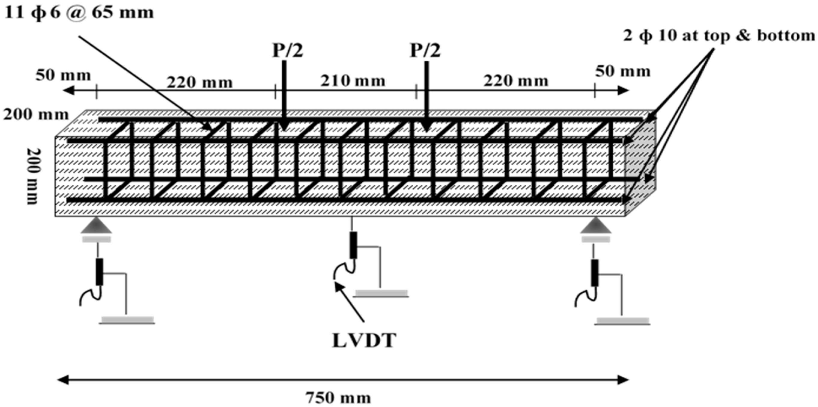
Figure 2.
Graduated magnifier. (a) On the crack; (b) on the beam.

Figure 3.
Beams condition in the Oman Sea. (a) Sea environment; (b) beams.

Figure 4.
Load-vertical displacement diagrams of pre-cracked specimens stored in: (a) water condition; (b) marine atmosphere zone. RC: Concrete with bar Reinforcement; (R+S)C: Concrete with Steel fiber and bar Reinforcement. Pr: Pre-cracked beam; MA: Marine Atmospheric; W: fresh Water.
Figure 4.
Load-vertical displacement diagrams of pre-cracked specimens stored in: (a) water condition; (b) marine atmosphere zone. RC: Concrete with bar Reinforcement; (R+S)C: Concrete with Steel fiber and bar Reinforcement. Pr: Pre-cracked beam; MA: Marine Atmospheric; W: fresh Water.
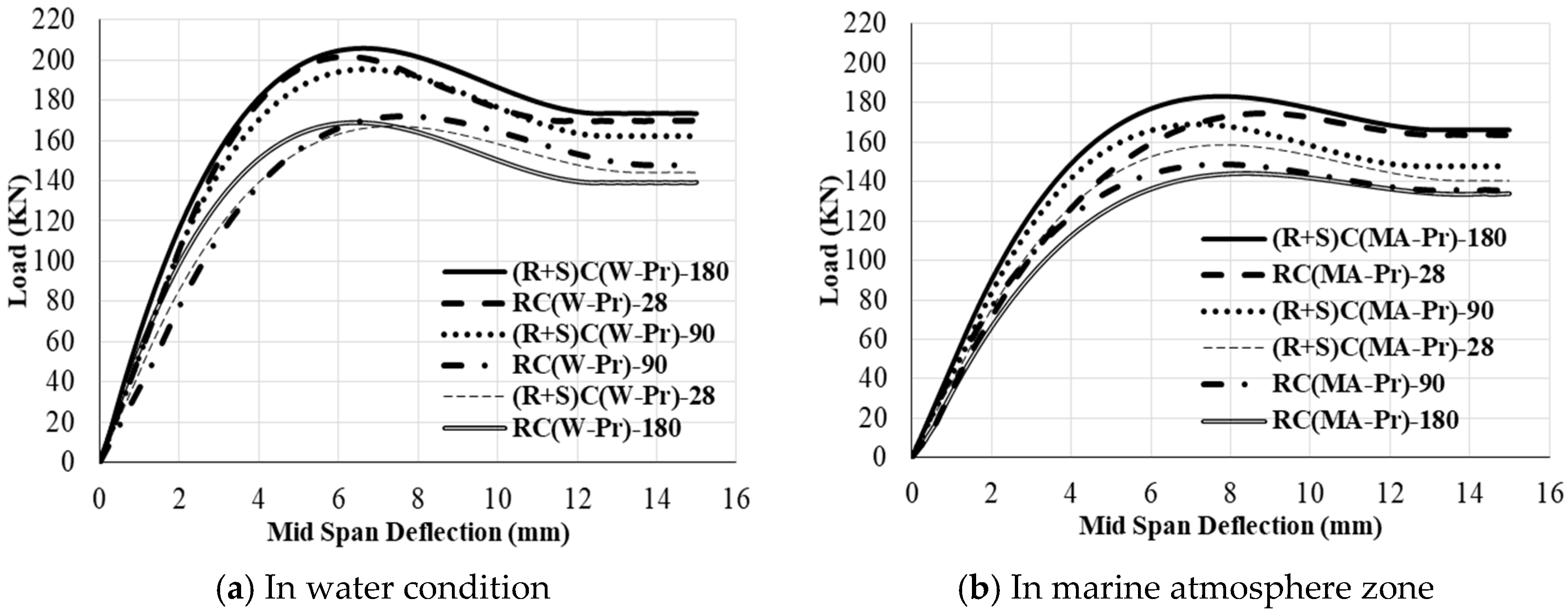
Figure 5.
Load-vertical deflection diagrams for un-cracked beams in the tidal zone at: (a) 28 days; (b) 90 days; (c) 180 days. PC: Plain Concrete; SFRC: Concrete with Steel fiber Reinforcement; Ti: Tidal zone; Un: Un-cracked beam.
Figure 5.
Load-vertical deflection diagrams for un-cracked beams in the tidal zone at: (a) 28 days; (b) 90 days; (c) 180 days. PC: Plain Concrete; SFRC: Concrete with Steel fiber Reinforcement; Ti: Tidal zone; Un: Un-cracked beam.

Figure 6.
Load-vertical deflection diagrams for pre-cracked beams in the tidal zone at: (a) 28 days; (b) 90 days; and (c) 180 days.
Figure 6.
Load-vertical deflection diagrams for pre-cracked beams in the tidal zone at: (a) 28 days; (b) 90 days; and (c) 180 days.


Table 1.
Concrete mixtures.
| Mixture Index | Water | Cement | Silica Fume | Fine Agg. | Coarse Agg. | Steel Fiber | SP |
|---|---|---|---|---|---|---|---|
| (kg/m3) | (%) | ||||||
| PC, RC | 160 | 360 | 40 | 758 | 1088 | --- | 1 |
| SFRC, (R+S)C | 160 | 360 | 40 | 824 | 996 | 0.5 | 1.2 |
PC: Plain Concrete; RC: Concrete with bar Reinforcement; SFRC: Concrete with Steel fiber Reinforcement; (R+S)C: Concrete with Steel fiber and bar Reinforcement; SP: Super-Plasticizer.
Table 2.
Details of the test condition.
| Mixture Index | Environment | Pre-Cracked | Steel Fiber | Steel Bar | ||
|---|---|---|---|---|---|---|
| Laboratory | Marine Zone | |||||
| Water | Atmospheric | Tidal | ||||
| PC (Ti) | ✓ | |||||
| SFRC (Ti-Un) | ✓ | ✓ | ||||
| RC (Ti-Un) | ✓ | ✓ | ||||
| (R+S)C (Ti-Un) | ✓ | ✓ | ✓ | |||
| SFRC (Ti-Pr) | ✓ | ✓ | ✓ | |||
| RC (Ti-Pr) | ✓ | ✓ | ✓ | |||
| RC (MA-Pr) | ✓ | ✓ | ✓ | |||
| RC (W-Pr) | ✓ | ✓ | ✓ | |||
| (R+S)C (Ti-Pr) | ✓ | ✓ | ✓ | ✓ | ||
| (R+S)C (MA-Pr) | ✓ | ✓ | ✓ | ✓ | ||
| (R+S)C (W-Pr) | ✓ | ✓ | ✓ | ✓ | ||
Ti: Tidal zone; Un: Un-cracked beam; Pr: Pre-cracked beam; MA: Marine Atmospheric; W: fresh Water; ✓: condition of performed test.
Table 3.
Chemical composition of Oman sea water.
| Composition | g/L |
|---|---|
| Cl− | 26.900 |
| So3− | 3.800 |
| Na+ | 13.100 |
| Mg2+ | 1.800 |
Table 4.
Maximum load capacity (Pmax) and Flexural Strength (fr) results.
| Mixture Index | Pmax (kN) | fr (MPa) | ||||
|---|---|---|---|---|---|---|
| 28 (Days) | 90 (Days) | 180 (Days) | 28 (Days) | 90 (Days) | 180 (Days) | |
| PC (Ti) | 74.05 | 60.21 | 53.97 | 6.02 | 4.89 | 4.39 |
| Variation (%) | 5.61 | 3.24 | 5.65 | 5.61 | 3.24 | 5.65 |
| SFRC (Ti-Un) | 108.43 | 80.64 | 67.04 | 8.81 | 6.55 | 5.45 |
| Variation (%) | 4.63 | 5.61 | 3.35 | 4.63 | 5.61 | 3.35 |
| RC (Ti-Un) | 174.11 | 149.61 | 131.55 | 14.15 | 12.16 | 10.69 |
| Variation (%) | 3.12 | 4.41 | 4.25 | 3.12 | 4.41 | 4.25 |
| (R+S)C (Ti-Un) | 198.54 | 170.16 | 156.02 | 16.13 | 13.83 | 12.68 |
| Variation (%) | 4.15 | 3.31 | 2.59 | 4.15 | 3.31 | 2.59 |
| SFRC (Ti-Pr) | 69.66 | 55.55 | 50.44 | 5.66 | 4.51 | 4.10 |
| Variation (%) | 2.61 | 2.59 | 3.35 | 2.61 | 2.59 | 3.35 |
| RC (Ti-Pr) | 180.03 | 141.65 | 125.29 | 14.63 | 11.51 | 10.18 |
| Variation (%) | 4.59 | 6.61 | 2.65 | 4.59 | 6.61 | 2.65 |
| RC (MA-Pr) | 174.28 | 148.49 | 144.06 | 14.16 | 12.07 | 11.70 |
| Variation (%) | 3.35 | 4.49 | 2.68 | 3.35 | 4.49 | 2.68 |
| RC (W-Pr) | 201.39 | 172.08 | 168.90 | 16.36 | 13.98 | 13.72 |
| Variation (%) | 3.19 | 2.89 | 3.78 | 3.19 | 2.89 | 3.78 |
| (R+S)C (Ti-Pr) | 156.70 | 165.54 | 181.45 | 12.73 | 13.45 | 14.74 |
| Variation (%) | 2.61 | 2.65 | 3.65 | 2.61 | 2.65 | 3.65 |
| (R+S)C (MA-Pr) | 158.47 | 168.93 | 183.10 | 12.88 | 13.73 | 14.88 |
| Variation (%) | 5.41 | 5.42 | 3.25 | 5.41 | 5.42 | 3.25 |
| (R+S)C (W-Pr) | 167.01 | 195.11 | 205.78 | 13.57 | 15.85 | 16.72 |
| Variation (%) | 2.65 | 3.54 | 1.12 | 2.65 | 3.54 | 1.12 |
Table 5.
Toughness (T) and Service Stiffness (S.S) results.
| Mixture Index | T (N.m) | S.S × 106 (N/m) | ||||
|---|---|---|---|---|---|---|
| 28 (Days) | 90 (Days) | 180 (Days) | 28 (Days) | 90 (Days) | 180 (Days) | |
| PC (Ti) | 58.13 | 47.41 | 47.35 | 55.54 | 39.13 | 29.44 |
| Variation (%) | 3.12 | 3.18 | 4.15 | 2.61 | 4.51 | 2.68 |
| SFRC (Ti-Un) | 398.59 | 292.05 | 290.85 | --- | --- | --- |
| Variation (%) | 2.15 | 3.61 | 3.14 | --- | --- | --- |
| RC (Ti-Un) | 2178.21 | 1808.36 | 1607.44 | 27.64 | 22.44 | 21.91 |
| Variation (%) | 3.15 | 4.16 | 4.78 | 4.65 | 3.23 | 1.25 |
| (R+S)C (Ti-Un) | 2434.49 | 2080.40 | 1903.79 | 35.04 | 30.21 | 25.44 |
| Variation (%) | 3.25 | 3.14 | 4.16 | 2.58 | 3.46 | 4.53 |
| SFRC (Ti-Pr) | 314.68 | 276.10 | 230.50 | --- | --- | --- |
| Variation (%) | 2.66 | 2.78 | 3.45 | --- | --- | --- |
| RC (Ti-Pr) | 2099.82 | 1712.92 | 1517.75 | 32.15 | 25.14 | 21.48 |
| Variation (%) | 1.25 | 2.68 | 2.54 | 3.25 | 2.45 | 2.64 |
| RC (MA-Pr) | 2067.02 | 1827.10 | 1749.92 | 24.43 | 23.57 | 21.72 |
| Variation (%) | 2.65 | 3.56 | 2.53 | 3.46 | 2.65 | 2.89 |
| RC (W-Pr) | 2402.02 | 2048.96 | 2044.09 | 45.09 | 29.67 | 28.90 |
| Variation (%) | 5.89 | 5.12 | 4.19 | 2.63 | 5.78 | 2.65 |
| (R+S)C (Ti-Pr) | 1873.45 | 2024.83 | 2167.06 | 28.61 | 29.21 | 30.58 |
| Variation (%) | 2.63 | 5.46 | 5.63 | 2.65 | 1.89 | 2.65 |
| (R+S)C (MA-Pr) | 1913.80 | 2038.86 | 2236.40 | 25.98 | 30.35 | 31.05 |
| Variation (%) | 2.43 | 4.56 | 5.26 | 3.19 | 2.14 | 2.56 |
| (R+S)C (W-Pr) | 2023.62 | 2339.04 | 2499.11 | 28.31 | 38.76 | 39.94 |
| Variation (%) | 2.64 | 3.15 | 1.16 | 2.48 | 2.35 | 2.59 |
© 2017 by the authors. Licensee MDPI, Basel, Switzerland. This article is an open access article distributed under the terms and conditions of the Creative Commons Attribution (CC BY) license (http://creativecommons.org/licenses/by/4.0/).
Share and Cite
MDPI and ACS Style
Barkhordari Bafghi, M.A.; Amini, F.; Safaye Nikoo, H.; Sarkardeh, H. Effect of Steel Fiber and Different Environments on Flexural Behavior of Reinforced Concrete Beams. Appl. Sci. 2017, 7, 1011. https://doi.org/10.3390/app7101011
AMA Style
Barkhordari Bafghi MA, Amini F, Safaye Nikoo H, Sarkardeh H. Effect of Steel Fiber and Different Environments on Flexural Behavior of Reinforced Concrete Beams. Applied Sciences. 2017; 7(10):1011. https://doi.org/10.3390/app7101011
Chicago/Turabian StyleBarkhordari Bafghi, Mohammad Ali, Fereydon Amini, Hamed Safaye Nikoo, and Hamed Sarkardeh. 2017. "Effect of Steel Fiber and Different Environments on Flexural Behavior of Reinforced Concrete Beams" Applied Sciences 7, no. 10: 1011. https://doi.org/10.3390/app7101011
Note that from the first issue of 2016, this journal uses article numbers instead of page numbers. See further details here.