
Fast Frequency Acquisition and Phase Locking of Nonplanar Ring Oscillators
by
 ,
,
Yunxiang Wang
*, 
Chen Wang
,
Yangping Tao
,
Yang Liu
,
Qiang Zhou
,
Jun Su
,
Zhiyong Wang
,
Shuangjin Shi
and
Qi Qiu
School of Optoelectronic Information, University of Electronic Science and Technology of China, Chengdu 610054, China
*
Author to whom correspondence should be addressed.
Appl. Sci. 2017, 7(10), 1032; https://doi.org/10.3390/app7101032
Submission received: 26 August 2017
/
Revised: 30 September 2017
/
Accepted: 4 October 2017
/
Published: 9 October 2017
(This article belongs to the Special Issue Solid State Lasers Materials, Technologies and Applications)
Abstract
:Optical phase locking is a critical technique in space coherent optical communication and active coherent laser beam combining. In a typical optical phase locking loop based on nonplanar ring oscillators, the pull-in range is normally less than 1 MHz, limited by loop delay and frequency tuning bandwidth of the laser source. Phase locking cannot be achieved at large initial frequency differences. In this work, a fast laser frequency acquisition method is demonstrated. The frequency difference between the signal and local lasers was measured via frequency dividing and period counting, and the frequency control signal was generated by a frequency discrimination and control module, to reduce the frequency difference to the pull-in range of the loop. Under the coordinating function of the loop filter and the frequency discrimination and control module, phase locking under a large initial frequency difference was achieved. The frequency acquisition range reached 164 MHz, and the acquisition and locking time was measured to be 440 ms. Additionally, the acquisition time was shortened with the decrease in initial frequency difference.
1. Introduction
An optical phase locking loop (OPLL) plays an important role in space homodyne coherent optical communication systems, which have a significant advantage in receiving sensitivity. Gbps-level LEO-LEO [1], LEO-GEO [2], LEO-GS [3], and GEO-GS [4] communication links were verified, where LEO, GEO and GS denoted low earth orbit satellites, geostationary earth orbit satellite, and ground station, respectively. Compared to electrical wave sources in an electrical PLL, laser sources have a wider line width and a faster frequency drift [5], which result in difficult frequency acquisition and poor tracking performance. Early OPLLs were based on gas laser sources. A. L. Acholtz et al. achieved phase locking of CO2 lasers and 100 Mbps homodyne communication [6]. However, limited by certain disadvantages in lifespan, volume, and efficiency, it is hard for gas lasers to meet certain requirements in space applications. The development of optical communication has greatly promoted the progress of semiconductor laser technology. S. Norimatsu et al. achieved phase locking of an external cavity semiconductor laser with a residual phase error of 7.4° [7]. Although semiconductor lasers have a small size and low cost, the linewidth of these devices is relatively wide, or the phase noise is large, which leads to losing lock or large residual phase error. Recently, integrated OPLLs based on semiconductor lasers have been studied intensively. Such loops have potential applications in optical frequency synthesis [8] and microwave photonics [9]. Integration of OPLLs reduces the loop delay, broadens the loop bandwidth, and improves the loop stability [10]. Thanks to the intensive study of diode-pumped solid-state lasers (DPSSL) over the last three decades, their performance has greatly improved in coherence, service life, and reliability. Among DPSSLs, nonplanar ring oscillators (NPROs) have a narrow linewidth (<1 kHz), low intensity noise (relative intensity noise <−140 dB/Hz), and good frequency stability. Due to the merit of a narrow linewidth, in OPLL applications, small residual phase error can be obtained. In homodyne coherent optical communication systems, small residual phase error is conducive to an improvement in the receiving sensitivity, which is important for space communication systems. Until now, NPRO is the only laser source that has been verified in orbit for applications of homodyne coherent optical communication, to the best of our knowledge. We believe that NPRO is, up to now, the first-choice laser source in space homodyne coherent optical communication systems.
For OPLLs based on NPRO, F. Herzog presented the scheme and performance of a dither loop, which did not require residual carrier transmission [11]. T. Ando et al. studied phase locking stability of OPLLs based on NPRO [12]. The authors analyzed the effect of response bandwidth of frequency tuning on phase locking precision [13]. Frequency acquisition performance is also quite important for phase locking loops. Frequency acquisition schemes based on a bang-bang phase detector [14] and a Hogge phase detector [15] have been reported in electrical PLLs. The range of initial frequency difference (or offset) between signal laser and local laser is larger in OPLLs, compared with electrical PLLs, and this is mainly due to laser frequency drift. Even under the condition of precise temperature control, the initial frequency offset can still be around 100 MHz. In addition, for OPLLs based on NPROs, the response bandwidth of the frequency tuning of the laser source is narrower, and loop delay is much longer, compared to electrical PLLs. Therefore, the lock-in range and pull-in range of an OPLL are much narrower. The frequency acquisition range, for OPLLs based on NPROs, should start from tens of kHz to more than 100 MHz. Thus, a special acquisition scheme with a wide range, high speed, and good compatibility with loop filters should be proposed for OPLLs based on NPROs. The frequency sweeping technique based on laser crystal temperature turning was used, with a frequency acquisition time longer than 10 s [2]. For this technique, if the loop lost locking due to a small frequency step during normal operation, it might also need more than 10 s for relocking. As the link duration of inter-satellite communication is typically in the range of 100–200 s for LEO-to-LEO links [1], the acquisition time should be reduced significantly to less than a few seconds, less than 1 s ideally. A shorter acquisition time means a longer communication time and more collected data. In this work, a faster frequency acquisition was achieved via frequency discrimination and piezoelectric frequency control. In addition, smooth continuity between the frequency acquisition process and the phase locking process was achieved. The frequency acquisition range reached 164 MHz, and the acquisition and locking time is less than 0.5 s.
2. Design of the OPLL
A block diagram of the OPLL is shown in Figure 1. The signal and local lasers were both NPROs, with two signal input ports for temperature and piezoelectric-transducer (PZT) frequency tuning, respectively. The temperature of the laser crystals was precisely controlled via a proportional–integral–derivative (PID) controller to keep the laser frequency stable. The control precision was 0.01 K for 1 h and 0.03 K for 8 h. The thermal tuning coefficient of Nd:YAG NPRO was 3 GHz/K. The typical frequency drift was measured to be around 30 MHz for 1 h and 100 MHz for 8 h. A piezoelectric element was bonded to the upper nonoptical face of the Nd:YAG crystal. The applied voltage can slightly change the dimension and refraction index of the laser crystal. Thus, the laser frequency was tuned. The PZT tuning coefficient was 1.6 MHz/V, and the response bandwidth was about 100 kHz.
The output lights of local and signal lasers were combined and mixed via a 50/50 fiber coupler. Two output beat signals with a 180° phase difference were sent to the balanced photodetector, which had a model number of PDB480C and was made by Thorlabs, Inc. (Newton, NJ, USA). The converted electrical beat signal, acting as a phase error signal, was sent to the loop filter and the frequency discrimination and control module (FDCM). Vc1 and Vc2 are the output signal amplitude of the loop filter and FDCM, respectively. The loop filter was an active proportional-plus-integral filter, where the first time constant τ1 = 3 ms and the second time constant τ2 = 5 µs. The main function of the loop filter was locking the phase, as the beat frequency falls into the pull-in range of the loop, which was around 700 kHz. The FDCM was used for the acquisition of signal frequency to keep the beat frequency below the pull-in range. Vc1 and Vc2 were amplified and added in the PZT driver, where the gain values G1 and G2 were 9 and 18, respectively. The output voltage amplitude of the PZT driver was ±190 V.
3. Principle of Frequency Acquisition
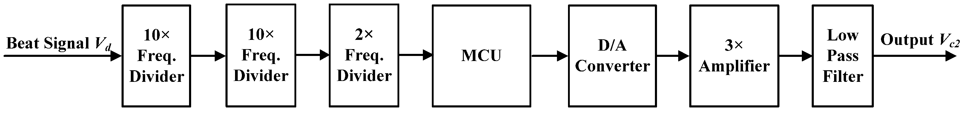
In the FDCM, the beat signal frequency is measured digitally, and a control signal is generated for frequency acquisition. A block diagram of the FDCM is shown in Figure 2. The frequency of the beat signal is firstly divided by 200 and converted into square pulses. The dividable frequency ranges from 10 kHz to 300 MHz. The pulse repetition frequency is measured via a microprogrammed control unit (MCU). The measuring period is set to be 5 ms. From the measured frequency in the current measuring period and the previous period, the frequency control direction and the frequency shift amount were obtained. An MCU generates corresponding binary data to the digital/analog (D/A) converter, in which the frequency control signal is generated. After passing through the amplifier, the control signal is sent to a low pass filter. It is then sent to the Vc2 port of the PZT driver. The low pass filter is essential for stable phase locking. In the locking status of the OPLL, the phase step and minor frequency step can cause a transient response in the phase error signal. Some frequency steps might be caused by the high frequency components of the D/A-converted signal. If the amplitude of the transient response signal reaches the threshold of the FDCM, it will function and generate a small frequency shifting signal. This is a false shifting signal and might result in losing lock. With a low pass filter of a 400 Hz bandwidth, the shifting signal is smoothed. The phase locking loop can precisely track the smoothed minor frequency shift, and keep a stable residual phase error. One frequency control cycle includes a frequency measuring period, 5 ms, and a frequency shifting period, 1 ms. The step response time of the low pass filter is close to 1 ms. Thus, the frequency shifting period is set to 1 ms.
Figure 3 shows the flow chart of the frequency discrimination and control program. The program is mainly achieved via an MCU. After program initialization, pulses that are sent to the module during the measuring period are counted. The frequency difference ∆fp in the current measuring period is computed from the counted pulse number. If ∆fp is less than critical frequency difference ∆fc, then the frequency locking is achieved. Thus, the FDCM will maintain the frequency control voltage, and the loop will be locked under the function of the loop filter. The lock-in range and pull-in range of the loop are 15 kHz and 700 kHz, respectively. The critical frequency difference ∆fc can be set to 40 kHz, with a locking time less than 1 ms under the function of the loop filter. If ∆fp is larger than the frequency difference in the last measuring period, ∆fb, then the frequency control direction is incorrect. If the current frequency control cycle is the second cycle, the wrong control direction is caused by a random chosen direction in the first frequency control cycle. Otherwise, the wrong control direction is caused by fast laser frequency drift during the last frequency control cycle. The frequency control direction will thus be changed, and the frequency shift amount is determined by ∆fp and the PZT tuning coefficient. If ∆fp is less than ∆fb, then the frequency control direction is correct. The local laser frequency will be controlled in the correct direction until ∆fp is less than ∆fc. Phase locking will thus be achieved via the loop filter.
The choice of division ratio is a tradeoff between the maximum measurable frequency (MMF) and measurement accuracy (MA). The crystal oscillating frequency of the MCU is 24 MHz, corresponding to a machine cycle of 0.5 µs. For a division ratio of 200, MMF is 200 MHz, and MA is 40 kHz. For a smaller division ratio, to get the same MA, a shorter frequency measuring period can be adopted, and a faster acquisition can be achieved. However, with the MCU used in this work, the MA is increased. At the initial frequency difference that equals MA, the phase locking time is longer under the function of the loop filter. If the phase locking time is longer than one frequency control cycle, the OPLL will become unstable. For example, if the division ratio is set at 100, a frequency measuring period can be set at 2.5 ms, and one frequency control cycle is 3.5 ms, with an MA of 80 kHz. At an initial frequency difference of 80 kHz, the phase locking time is close to 3.5 ms, and the loop operates at the critical region with poor stability. Moreover, for a higher division ratio, the MMF is decreased, which is also undesired. Thus, the optimum division ratio in this work is 200. If we could decrease the phase locking time, under the condition of a shorter loop delay and a wider loop bandwidth, a smaller division ratio is allowed. The output voltage range of the D/A converter is ±5 V. The converted signal has a total amplification of 54× before sending to the PZT port of the local laser.
4. Experimental Results
The phase locking loop was constructed according to Figure 1. First, the FDCM was turned off, and the initial frequency difference of the two lasers was controlled by adjusting the crystal temperature of the signal laser. At a set frequency difference, as the FDCM was turned on, frequency acquisition and phase locking were tested. In the experiments, the output signal of the loop filter, the PZT driving signal, and the laser beat signal were monitored.
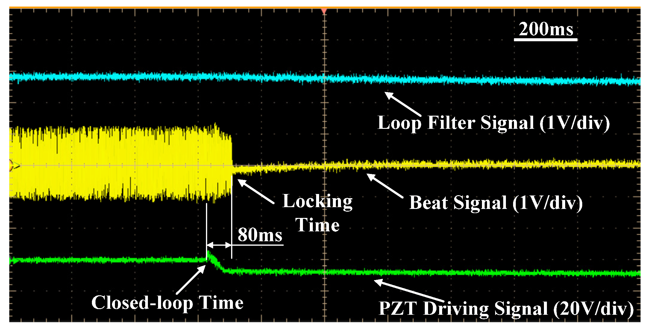
The frequency acquisition and phase locking process at an 8 MHz initial frequency difference is shown in Figure 4 with a time scale of 200 ms/div. At 630 ms, the FDCM was turned on, and the feedback control was started. After 80 ms, phase locking was achieved, as indicated by the beat signal (yellow). According to the frequency discrimination and control program, under the control of the FDCM, the local laser generated an initial frequency shift. As the change in frequency difference is measured, the direction of the frequency control and the frequency shift amount were determined. The main function of the initial frequency shift determined the right frequency control direction. After that, the frequency difference decreased to less than ∆fc, 40 kHz, as indicated by the PZT driving signal (green). For such a small frequency difference, the phase locking time based on the loop filter was quite short, shorter than 1 ms, which is negligible compared to the frequency acquisition time.
As the initial frequency difference increased to 164 MHz, the acquisition time was around 440 ms, as shown in Figure 5. As the beat signal was detected via the probe of the oscilloscope, the amplitude of the detected signal varied with the signal frequency in the acquisition process because impedance matching varied at different frequencies. For a higher initial frequency difference, the frequency discrimination and control would go wrong sometimes. The main reason for this is that the machine cycle of the MCU, compared to the divided beat signal period, was so long that the frequency could not be correctly measured. It could be improved by increasing the crystal frequency and the processing speed of the MCU. In order to guarantee the stability of the frequency control process, the local laser frequency shift was set to less than 3 MHz at every control step. For an even higher frequency shift step, the laser frequency would not reach a steady state at the end of the control period, causing inaccurate frequency measuring in the following measuring period, even leading to false control. As the initial frequency difference increased, more control periods were needed, and acquisition time was normally extended. In the frequency acquisition process, when the beat signal frequency was out of the pull-in range of the loop, the loop filter output a constant DC signal. Only as the beat frequency fell into the pull-in range of the loop did the loop filter signal have an obvious response, as shown in the figure by the blue line. According to the measurement of the laser frequency stability, the frequency drift of the beat signal of the two lasers was around 100 MHz in 8 h, under precise temperature control. The frequency acquisition range, 164 MHz, was significantly larger than the frequency drift range, so a stable loop operation was achievable.
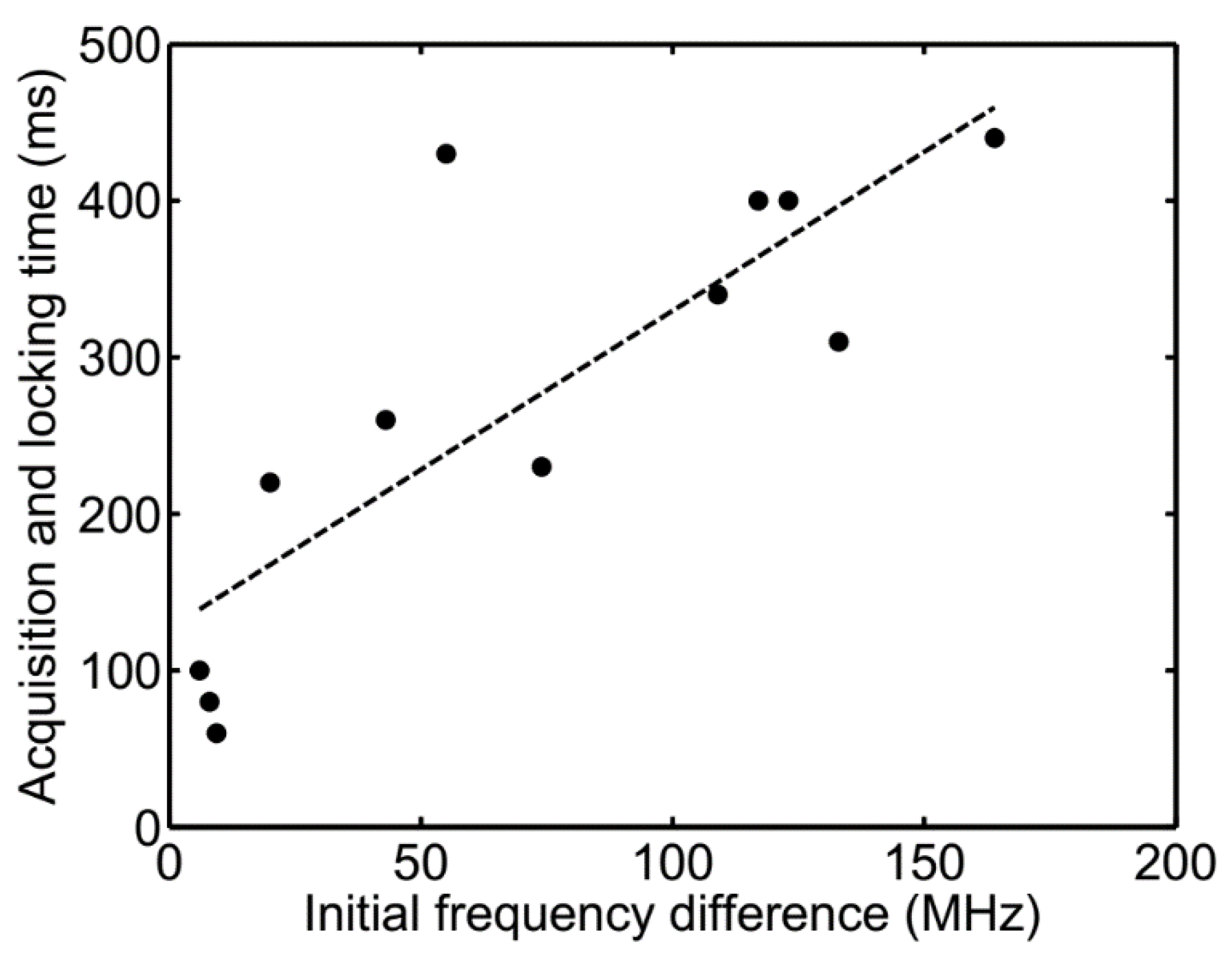
The frequency acquisition and phase locking time at different initial beat frequencies is shown in Figure 6. According to the frequency discrimination and control program, the theoretical minimum number of control cycles was equal to the initial frequency difference divided by the maximum frequency shift step of a given period, which was set to 3 MHz. As the time of one control cycle was set to 6 ms, minimum acquisition time could be computed. The actual acquisition time was usually longer, and had a certain degree of uncertainty. Main causes include uncertainty of the initial frequency shift direction, laser frequency drift during the acquisition process, and a shortened frequency shift step in the last few control cycles. The dashed line in Figure 6 is the linear fitting line with a slope of 2.03 ms/MHz. The slope corresponds to the ratio of time of one frequency control cycle, 6 ms, to the maximum frequency shift step in one cycle, 3 MHz. Compared to the frequency acquisition time achieved via the frequency sweeping technique based on laser crystal temperature turning, which was longer than 10 s [2], the acquisition time of this work was 1–2 orders of magnitude shorter.
5. Conclusions
Nonplanar ring oscillators have a high frequency stability, a narrow linewidth, and low intensity noise. These devices are becoming the preferred laser sources in coherent space optical communications. They can also be used in coherent laser beam combinations. In these applications, phase locking is the key technique. Traditionally, laser frequency acquisition based on temperature control consumes quite a long time. In this work, we designed and achieved a frequency acquisition sub-loop based on PZT control. The acquisition sub-loop operated coordinately with the phase locking loop based on the loop filter. The frequency acquisition range reached 164 MHz, with an acquisition time of less than 500 ms. For a smaller initial frequency difference, acquisition times decreased. This technique significantly shortens the frequency acquisition time, which makes the system reach work status much more quickly. In addition, by improving the processing speed of the control circuit, acquisition time can be further shortened.
Acknowledgments
This research is supported by the National Natural Science Foundation of China (Grant No. 61308041 and 61405030) and the PetroChina Innovation Foundation (Grant No. 2017D-5007-0603).
Author Contributions
Yunxiang Wang and Qi Qiu conceived and designed the experiments, Yangping Tao and Yang Liu designed the feedback circuits; Qiang Zhou and Zhiyong Wang performed the experiments; Jun Su and Shuangjin Shi analyzed the data; Chen Wang designed the nonplanar ring oscillators.
Conflicts of Interest
The authors declare no conflict of interest.
References
- Smutny, B.; Kaempfner, H.; Muehlnikel, G.; Sterr, U.; Wandernoth, B.; Heine, F.; Hildebrand, U.; Dallmann, D.; Reinhardt, M.; Freier, A.; et al. 5.6 Gbps Optical Intersatellite Communication Link. In Proceedings of the SPIE—The International Society for Optical Engineering, San Jose, CA, USA, 24 February 2009; No. 7199. pp. 601–608. [Google Scholar]
- Tröndle, D.; Pimentel, P.M.; Rochow, C.; Zech, H.; Muehlnikel, G.; Heine, F.; Meyer, R.; Philipp-May, S.; Lutzer, M.; Benzi, E.; et al. Alphasat-Sentinel-1A Optical Inter-Satellite Links: Run-Up For The European Data Relay Satellite System. In Proceedings of the SPIE—The International Society for Optical Engineering, San Francisco, CA, USA, 15 March 2016; No. 9739. pp. 201–206. [Google Scholar]
- Gregory, M.; Troendle, D.; Muehlnikel, G.; Heine, F.; Meyer, R.; Lutzer, M.; Czichy, R. 3 Years Coherent Space to Ground Links: Performance Results And Outlook For The Optical Ground Station Equipped with Adaptive Optics. In Proceedings of the SPIE—The International Society for Optical Engineering, San Francisco, CA, USA, 19 March 2013; No. 8610. pp. 401–413. [Google Scholar]
- Saucke, K.; Seiter, C.; Heine, F.; Gregory, M.; Tröndle, D.; Fischer, E.; Berkefeld, T.; Feriencik, M.; Feriencik, M.; Richter, I.; et al. The Tesat Transportable Adaptive Optical Ground Station. In Proceedings of the SPIE—The International Society for Optical Engineering, San Francisco, CA, USA, 15 March 2016; No. 9739. pp. 601–611. [Google Scholar]
- Kang, H.; Zhang, H.; Wang, D. Thermal-induced refractive-index planar waveguide laser. Appl. Phys. Lett. 2009, 95, 181102. [Google Scholar]
- Scholtz, A.L.; Leeb, W.R.; Philipp, H.K.; Bonek, E. Infra-Red Homodyne Receiver with Acousto-Optically Controlled Local Oscillator. Electron. Lett. 1983, 19, 234–235. [Google Scholar] [CrossRef]
- Norimatsu, S.; Iwashita, K.; Noguchi, K. 10 Gbit/s Optical PSK Homodyne Transmission Experiments Using External Cavity DFB LDs. Electron. Lett. 1990, 26, 648–649. [Google Scholar] [CrossRef]
- Arafin, S.; Simsek, A.; Kim, S.; Dwivedi, S.; Liang, W.; Eliyahu, D.; Klamkin, J.; Matsko, A.; Johansson, L.; Maleki, L.; et al. Towards Chip-Scale Optical Frequency Synthesis Based on Optical Heterodyne Phase-Locked Loop. Opt. Express 2017, 25, 681–695. [Google Scholar] [CrossRef] [PubMed]
- Balakier, K.; Fice, M.J.; Ponnampalam, L.; Seeds, A.J.; Renaud, C.C. Monolithically Integrated Optical Phase Lock Loop for Microwave Photonics. J. Lightwave Technol. 2014, 32, 3893–3900. [Google Scholar] [CrossRef]
- Lu, M.; Park, H.; Bloch, E.; Johansson, L.A.; Rodwell, M.J.; Coldren, L.A. An Integrated Heterodyne Optical Phase-Locked Loop with Record Offset Locking Frequency. In Proceedings of the 2014 Optical Fiber Communication Conference and Exhibition (OFC), San Francisco, CA, USA, 9–13 March 2014. [Google Scholar]
- Herzog, F. An Optical Phase Locked Loop for Coherent Space Communications. Ph.D. Thesis, Swiss Federal Institute of Technology, Zurich, Switzerland, 2006. [Google Scholar]
- Ando, T.; Haraguchi, E.; Tajima, K.; Hirano, Y.; Hanada, T.; Yamakawa, S. Optical Homodyne BPSK Receiver with Doppler Shift Compensation for LEO-GEO Optical Communication. In Proceedings of the 2013 Conference on Lasers and Electro-Optics Pacifc Rim, Kyoto, Japan, 30 June–4 July 2013. [Google Scholar]
- Wang, Y.; Qiu, Q.; Shi, S.; Su, J.; Liao, Y.; Xiong, C. High-precision optical phase locking based on wideband acousto-optical frequency shifting. Chin. Opt. Lett. 2014, 12, 021402. [Google Scholar] [CrossRef]
- Shu, G.; Choi, W.S.; Saxena, S.; Anand, T.; Elshazly, A.; Hanumolu, P.K. 8.7 A 4-to-10.5 Gb/s 2.2 mW/Gb/s continuous-rate digital CDR with automatic frequency acquisition in 65 nm CMOS. In Proceedings of the 2014 IEEE Interational Solid-State Circuits Conference Digest of Technical Papers (ISSCC), San Francisco, CA, USA, 9–13 February 2014; pp. 150–151. [Google Scholar]
- Huang, S.; Cao, J.; Green, M.M. An 8.2 Gb/s-to-10.3 Gb/s Full-Rate Linear Referenceless CDR Without Frequency Detector in 0.18 μm CMOS. IEEE J. Solid State Circuits 2015, 50, 2048–2060. [Google Scholar] [CrossRef]
Figure 1.
Block diagram of the optical frequency acquisition and the phase-locking loop.
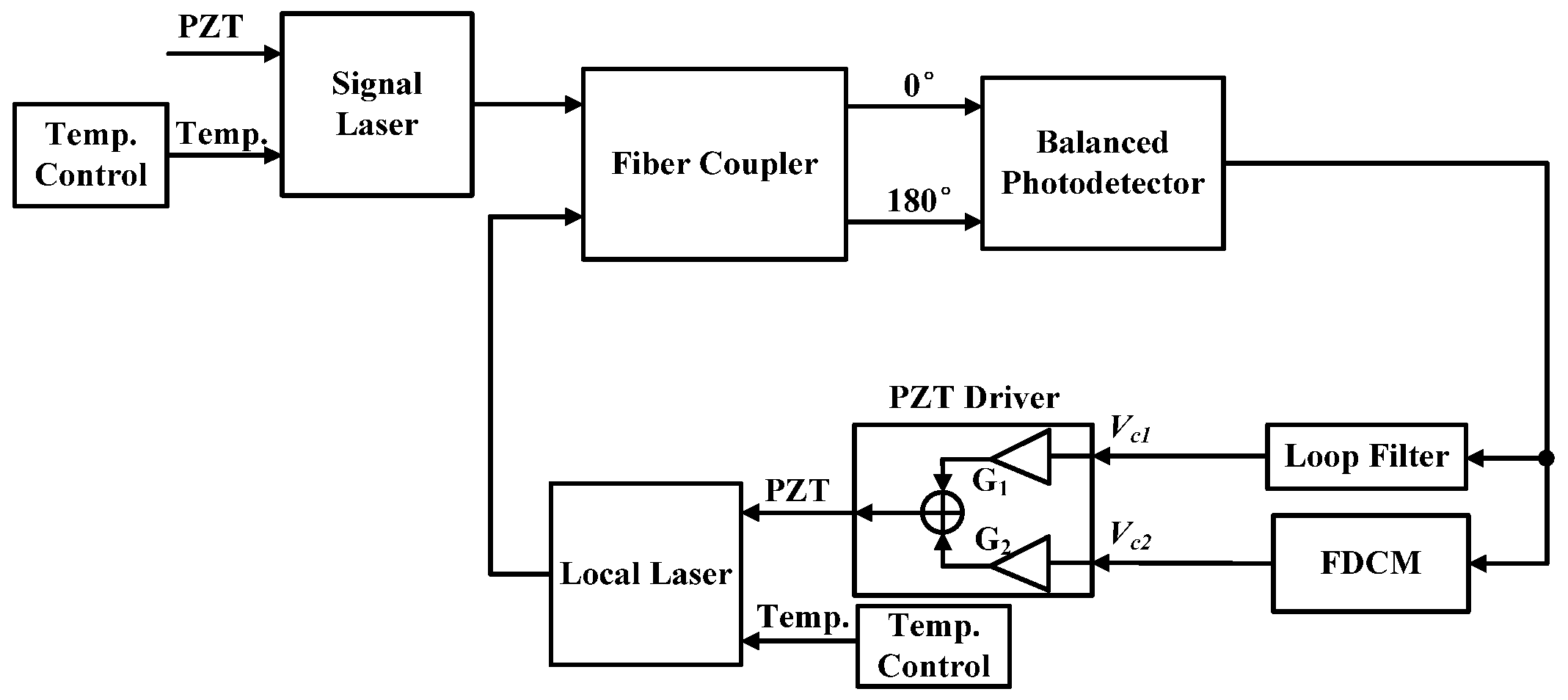
Figure 2.
Block diagram of the frequency discrimination and control module (FDCM).

Figure 3.
Flow chart of frequency discrimination and control program.

Figure 4.
Frequency acquisition and phase locking process at an 8 MHz initial frequency difference.

Figure 5.
Frequency acquisition and phase locking process at a 164 MHz initial frequency difference.
Figure 5.
Frequency acquisition and phase locking process at a 164 MHz initial frequency difference.
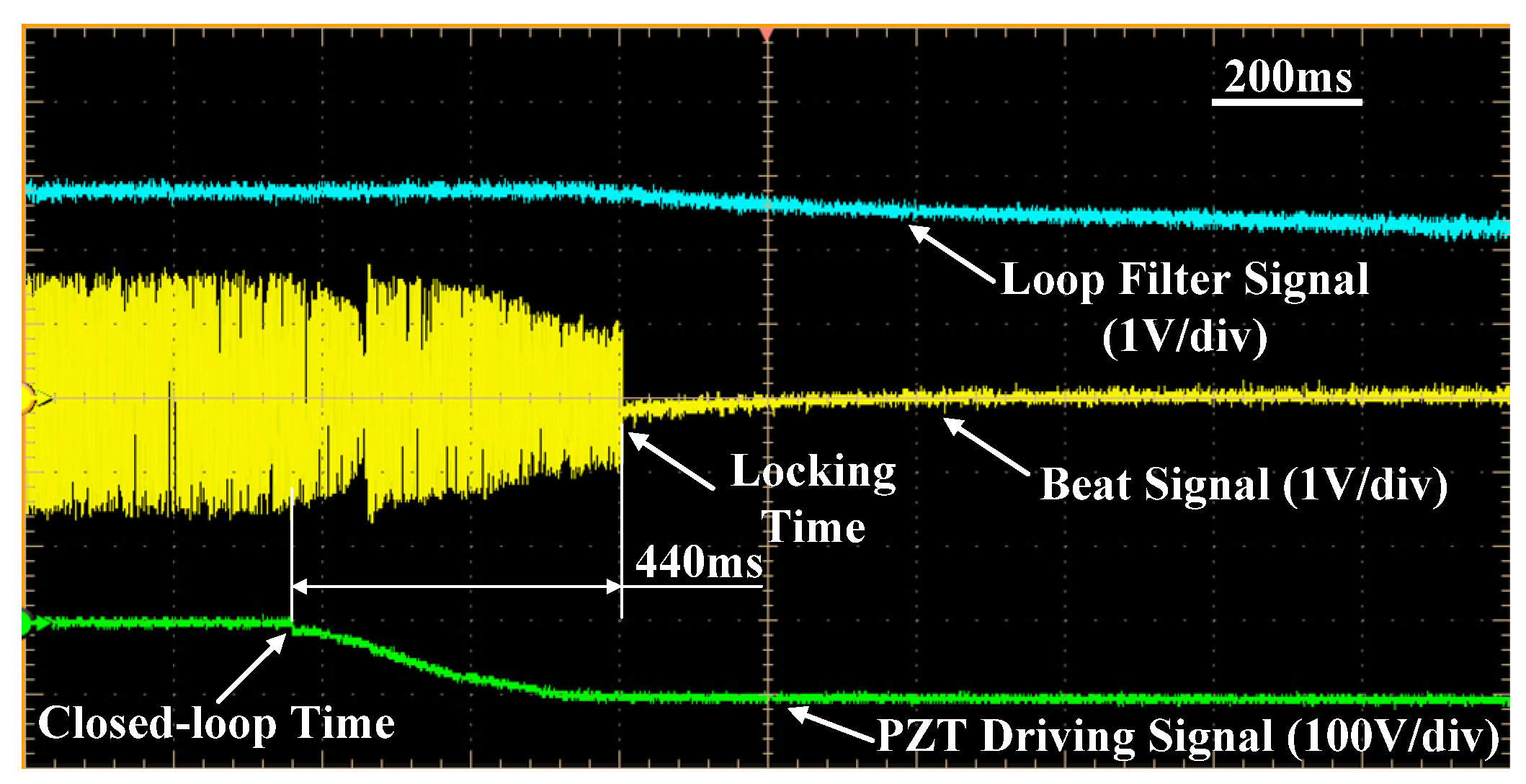
Figure 6.
Measured frequency acquisition and phase locking time vs. the initial frequency difference. The dashed line is the linear fitting line.
Figure 6.
Measured frequency acquisition and phase locking time vs. the initial frequency difference. The dashed line is the linear fitting line.
© 2017 by the authors. Licensee MDPI, Basel, Switzerland. This article is an open access article distributed under the terms and conditions of the Creative Commons Attribution (CC BY) license (http://creativecommons.org/licenses/by/4.0/).
Share and Cite
MDPI and ACS Style
Wang, Y.; Wang, C.; Tao, Y.; Liu, Y.; Zhou, Q.; Su, J.; Wang, Z.; Shi, S.; Qiu, Q. Fast Frequency Acquisition and Phase Locking of Nonplanar Ring Oscillators. Appl. Sci. 2017, 7, 1032. https://doi.org/10.3390/app7101032
AMA Style
Wang Y, Wang C, Tao Y, Liu Y, Zhou Q, Su J, Wang Z, Shi S, Qiu Q. Fast Frequency Acquisition and Phase Locking of Nonplanar Ring Oscillators. Applied Sciences. 2017; 7(10):1032. https://doi.org/10.3390/app7101032
Chicago/Turabian StyleWang, Yunxiang, Chen Wang, Yangping Tao, Yang Liu, Qiang Zhou, Jun Su, Zhiyong Wang, Shuangjin Shi, and Qi Qiu. 2017. "Fast Frequency Acquisition and Phase Locking of Nonplanar Ring Oscillators" Applied Sciences 7, no. 10: 1032. https://doi.org/10.3390/app7101032
Note that from the first issue of 2016, this journal uses article numbers instead of page numbers. See further details here.