3D Suspended Polymeric Microfluidics (SPMF3) with Flow Orthogonal to Bending (FOB) for Fluid Analysis through Kinematic Viscosity


1
Optical-Bio Microsystems Lab., Department of Mechanical and Industrial Engineering, Concordia University, Montreal, QC H3G 1M8, Canada
2
Robotic Assisted Minimally Invasive Surgery Lab., Department of Mechanical and Industrial Engineering, Concordia University, Montreal, QC H3G 1M8, Canada
*
Author to whom correspondence should be addressed.
Appl. Sci. 2017, 7(10), 1048; https://doi.org/10.3390/app7101048
Submission received: 21 August 2017
/
Revised: 2 October 2017
/
Accepted: 7 October 2017
/
Published: 13 October 2017
(This article belongs to the Special Issue Microsystems for Bio Applications)
Abstract
:Measuring of fluid properties such as dynamic viscosity and density has tremendous potential for various applications from physical to biological to chemical sensing. However, it is almost impossible to affect only one of these properties, as dynamic viscosity and density are coupled. Hence, this paper proposes kinematic viscosity as a comprehensive parameter which can be used to study the effect of fluid properties applicable to various fluids from Newtonian fluids, such as water, to non-Newtonian fluids, such as blood. This paper also proposes an ideal microplatform, namely polymeric suspended microfluidics (SPMF3), with flow plane orthogonal to the bending plane of the structure, along with tested results of various fluids covering a wide range of engineering applications. Kinematic viscosity, also called momentum diffusivity, considers changes in both fluid intermolecular forces and molecular inertia that define dynamic viscosity and fluid density, respectively. In this study a 3D suspended polymeric microfluidic system (SPMF3) was employed to detect changes in fluid parameters such as dynamic viscosity and density during fluid processes. Using this innovative design along with theoretical and experimental results, it is shown that, in fluids, the variations of fluid density and dynamic viscosity are not easily comprehensible due to their interconnectivity. Since any change in a fluid will affect both density and dynamic viscosity, measuring both of them is necessary to identify the fluid or process status. Finally, changes in fluid properties were analyzed using simulation and experiments. The experimental results with salt-DI water solution and milk with different fat concentrations as a colloidal fluid show that kinematic viscosity is a comprehensive parameter that can identify the fluids in a unique way using the proposed microplatform.
1. Introduction
Fluid density and viscosity result in inertia, or resistance to move or flow. If we assume that fluid molecules are located in multiple sheets placed one on top of another, viscosity is defined as the friction force between these sheets. Based on the application and fluid properties, two types of fluid viscosity, called dynamic viscosity and kinematic viscosity, are defined. Dynamic viscosity is mainly used for comparing different fluids based on their flow resistivity. This resistance comes from the Van der Waals force among molecules of fluid layers. The more force which comes from the electron cloud density of atoms, the higher the viscosity effect on fluid flow. The fluid molecules have a specific mass which comes into effect when kinematic viscosity is being employed. The higher the molecule mass is, the more it produces inertia at the molecular level, thus the lower the tendency (or more inertia) to move and transfer momentum to other layers.
The fluids with their dynamic viscosity dependent on shear rate are called non-Newtonian fluids and the rest are defined as Newtonian fluids. For example, blood viscosity changes with shear rate which results in lower viscosity in capillaries and higher viscosity in larger veins [1]. In other words, an external force applied to non-Newtonian fluids affects their viscosity and shear rate [2,3]. In order to interpret this non-Newtonian effect, a deeper understanding of kinematic viscosity is required. The non-Newtonian behavior is mainly due to the structural organization of molecules inside the fluid. For example, in colloidal fluids such as blood, the shear thinning behavior is because of segregation of particles and phases inside the fluid. Thus, connection between phases inside a non-Newtonian fluid will increase the fluid viscosity and density in a control volume, such as a capillary. Here, the definition of kinematic viscosity, υ = μ/ρ, affects the connection among phases inside a fluid in a way that not only changes the distance between them and their interaction forces, but also the fluid density in a control volume. Thus, kinematic viscosity varies with shear stress in non-Newtonian fluids. Any variation in fluid substances during a process affects both density and viscosity, therefore another comprehensive parameter which considers both is required in order to identify and study the fluid in a more comprehensive way during different processes.
In order to measure fluid parameters, there has been lots of interest towards employing microelectromechanical systems (MEMS) based viscometers due to their accuracy, simplicity and compatibility with different industries. There are three types of microsensors that have been used mostly in dynamic viscosity measurement: vibrating microcantilever [4] and plate, quartz crystal resonators [5] and microfluidic systems [6]. The governing equations of these micro-viscometers—vibrating microcantilever, Equation (1); quartz crystal resonators, Equation (2); and transduction principle of the microfluidic sensors—are as follows.
where μ is fluid dynamic viscosity, ρ is fluid density, is frequency response in a vacuum, is frequency in fluid medium, b is microcantilever width and is hydrodynamic function in the governing function for microcantilevers. In quartz crystal resonators, is elastic modulus, is density of the quartz crystal, and are frequency shift and natural frequency of free crystal, respectively.
Quartz resonators employ piezoelectric surfaces which can make high frequency vibrations with low amplitude. The measured resonance feedback is proportional to fluid density and viscosity that is modified when a change happens in the shear stress of fluid [7,8,9,10]. This method has been successfully employed in industrial real-time detection applications [11,12] even though some ranges of fluid viscosity—specifically in comparative applications—are not detectable due to the low vibration amplitude of this measurement system (Agoston, et al., 2005). In biological applications, micromachined quartz resonators have been used as density and viscosity measurement systems [13,14]. However, the piezoelectric films are not easily integrable during microfabrication [15].
Resonating cantilevers and plates have been the most frequently used type of MEMS viscometers [16,17,18] which are usually actuated by means of piezoelectric material [19,20,21], magnetic field [22,23,24] or alternating electricity current [25,26,27]. Theoretical studies and models connect variations in fluid density and viscosity to the shift in resonant frequency and quality factor, respectively [28,29,30].
There are not many viscometers designed based on only fluid flow in a microfluidic channel. One example, used for viscometric study of blood, was the integration of two electrodes in a microchannel and monitoring of the changes in fluid impedance [31]. Considering the non-Newtonian effect of fluids, some MEMS-based microplate oscillating systems have been designed and the governing equations were derived [26] as Equation (3),
where is oscillation frequency, is motion amplitude, B and a are plate width and length, μ is fluid dynamic viscosity, ρ is fluid density and P is average oscillation power over a period.
As is apparent from the abovementioned formula, Equation (3), frequency change in microsystems submerged in fluid is dependent on both density and viscosity (μ and ρ). In other words, to extract viscosity using these microsystems, a knowledge of fluid density is required. Otherwise, in some articles, another parameter such as quality factor is measured in order to have another equation for the two unknowns.
Although these methods are addressing the viscosity measurement, these formulas are mainly useful for Newtonian and single-phase fluids where the viscosity changes can be assumed negligible with respect to shear stress, and density can be measured with other methods. However, in non-Newtonian or multi-phase fluids, both density and viscosity are subject to change at different flow rates. Thus, the fluid has these two parameters, namely, dynamic viscosity and density, interconnected. To study and measure fluid properties, kinematic viscosity captures this interconnectivity of fluid properties at different flow conditions in addition to being measured easily by the proposed platform.
Kinematic viscosity measurement is most frequently used in chemical processing and oil industries where fluid is sheared and displaced at the same time. On the other hand, the processing of chemicals such as crude oil is happening during a long process, and in each step a certain fluid with some concentration is being separated/added while the rest goes on to the next processing machine. During each process, it is very difficult to calculate and measure fluid dynamic viscosity or density as the concentration of each parameter should be precisely determined while the process is ongoing quickly. Thus, kinematic viscosity can be used as a single parameter in this industry to qualify the chemical’s specifications at a certain processing step. In order to obtain kinematic viscosity from dynamic viscosity, measuring of solution density—which changes with different concentration—is required. Here, to get rid of this density measurement, the fluid specifications can be identified using kinematic viscosity which can be measured as a solution parameter using devices such as capillary viscometers.
Kinematic viscosity can be interpreted as momentum diffusivity between adjacent fluid layers. In other words, momentum flux between fluid layers is proportional to the gradient of mass flux there. This momentum diffusivity is related to density and dynamic viscosity of fluid which, in total, is named kinematic viscosity. Thus, kinematic viscosity represents momentum transport per unit area between layers. In other words, kinematic viscosity determines how fast a fluid flows when a certain force (shear) is applied to it. Dynamic viscosity mainly considers the inter-molecular forces which determine the friction force that stops or slows a fluid from flowing.
In all of the abovementioned measurement systems, dynamic viscosity detection is linked to density. Therefore, kinematic viscosity has not been measured directly using the micro-viscometers, but has been measured indirectly by dividing μ by ρ. This indirect measurement is due to the design of vibrating systems in which the fluid under study is flown over the cantilever or plate. In this study, the fluid has been injected inside a suspended microfluidic and passed through a predesigned aperture or nozzle which directly measured kinematic viscosity, without measuring dynamic viscosity and density separately. Dynamic viscosity and density have different physical meanings, but interpreting these two parameters together will lead us to a unique parameter—kinematic viscosity—which will allow us to understand and detect changes in fluid properties.
2. Materials and Methods
2.1. 3D Suspended Polymeric Microfluidics
All of the applied micro-viscometers work based on moving a microstructure inside a fluidic medium. Since this motion replaces a fluid mass while shearing it, the density effect and consequent density measurement are inevitable in this kind of measurement system. On the other hand, any variation in solution concentration will change both density and viscosity. Thus, in order to identify a fluid under different processes, a kinematic viscosity measurement system is introduced in this study. The proposed microsystem is designed based on the capillary kinematic viscosity measurement concept [32] which is depicted simply in Figure 1.
The earlier system works based on free fall of fluid due to its mass which creates a constant pressure difference at the two ends of the target zone. The time to travel between two graduation marks—start and end—on the viscometer will result in the fluid kinematic viscosity measurement. Since the only acting forces are fluid shear force and weight in a constant volume between the positions, measuring the time when fluid falls between these two marks on the viscometer is proportional to fluid kinematic viscosity as shown in the following formulation [33], Equation (4).
where a is the capillary radius, V is the fluid volume between marks, l is the distance of two measurement points, Q is the flow rate, g is the acceleration due to gravity, μ is the dynamic viscosity, υ is the kinematic viscosity, ρ is the density, t is time and h is the pressure difference height.
The 3D suspended microfluidic system is proposed in this study to detect the flow and its properties such as density and viscosity. After considering the abovementioned viscometers and flowmeters, a microcantilever with embedded microchannel design was noticed that had a very interesting design used to detect fluid flow, even though this capability had not been considered by its initiators. This microsystem [34,35] was comprised of a U-shape microchannel inside a microcantilever (Figure 1c). The suspended microchannel was used to detect microparticles and cells using either frequency shift or the deflection measurement method. However, another interesting aspect of this embedded microfluidics is flow forces applied to the microcantilever. The change in flow direction creates momentum force that will be modified when fluid properties such as kinematic viscosity vary. Detecting these forces can be an innovative way to study flow properties in a dry and closed-loop system.
Since the microchannel plane is parallel to the microcantilever plane, the applied flow forces were not strong enough to bend the microcantilever (Figure 2a). Hence, these systems were microstructures for only frequency measurements. However, in this study, this issue is resolved by designing the microchannel plane to be orthogonal to the neutral or bending plane (Figure 2b). Comparing the following results of the present paper with previous studies [34,36] shows that the new design will increase the system sensitivity to 5 times more than the earlier designs. The increased sensitivity is due to the change of flow force direction orthogonal to the low stiff plane of the microcantilever.
The novel suspended microsystem works based on the constant flow rate inside a microfluidic channel which creates a constant pressure difference and velocity difference at two ends of the aperture or nozzle. Considering the space between two ends as a control volume, pressure and velocity differences at the ends make flow forces which are applied to the microcantilever. The designed microchannel is embedded inside a microcantilever in order to apply the flow forces to the microstructure. These flow forces should deflect the microcantilever, depending on changes in flow or fluid properties.
The force balance equation and capillary measurement for the microfluidic system, Equation (5), results in Equation (6) for kinematic viscosity measurement using the SPMF3. Following are the equations of both systems and their relation to kinematic viscosity. On substituting for from Equation (5) into Equation (6), one can obtain the relation to kinematic viscosity, υ.
where A is the cross section area, l is the nozzle length between start and end marks, and are the pressure and velocity difference between two graduation marks, is cantilever stiffness, is the mass flow rate and δ is cantilever deflection. If the volume between the two marks is considered as a control volume, f shows the applied force due to pressure and velocity difference between two ends of this volume. These differences are created as a result of changes in flow direction and channel cross section area. The applied force is equal to the cantilever spring force, . The abovementioned formula, Equation (6), shows a linear relationship between the microcantilever deflection and kinematic viscosity of the fluid as in Equation (7).
2.2. Fabrication of the Device
In order to fabricate the 3D microchannel inside a microcantilever structure, three different layers were designed, fabricated and bonded together to create the whole suspended microfluidics. These three layers consist of two microchannel layers and one nozzle layer. As is shown in Figure 3, two different molds—one for microchannel layers and one for the nozzle layer—are fabricated using the soft lithography method. According to the designed microcantilever thickness, SU8-2075 was used as a photoresist in the mold fabrication process. Then, two microchannel layers were fabricated using the microchannel mold and bonded to a nozzle layer in between to form the 3D suspended microfluidic system. The bonding process is done using a plasma activated technique after ensuring alignment between microchannel and nozzle layers under a wide-range microscope. Failure in bonding strength and alignment will result in misalignment between layers. These microchannel and nozzle layers are made of Polydimethylsiloxane (PDMS) which also increases the amount of deflection or sensitivity to small loads due to low elastic modulus. The detailed view of the microcantilever tip shows the embedded microchannel, flow and deflection directions (Figure 3c).
3. Results and Discussion
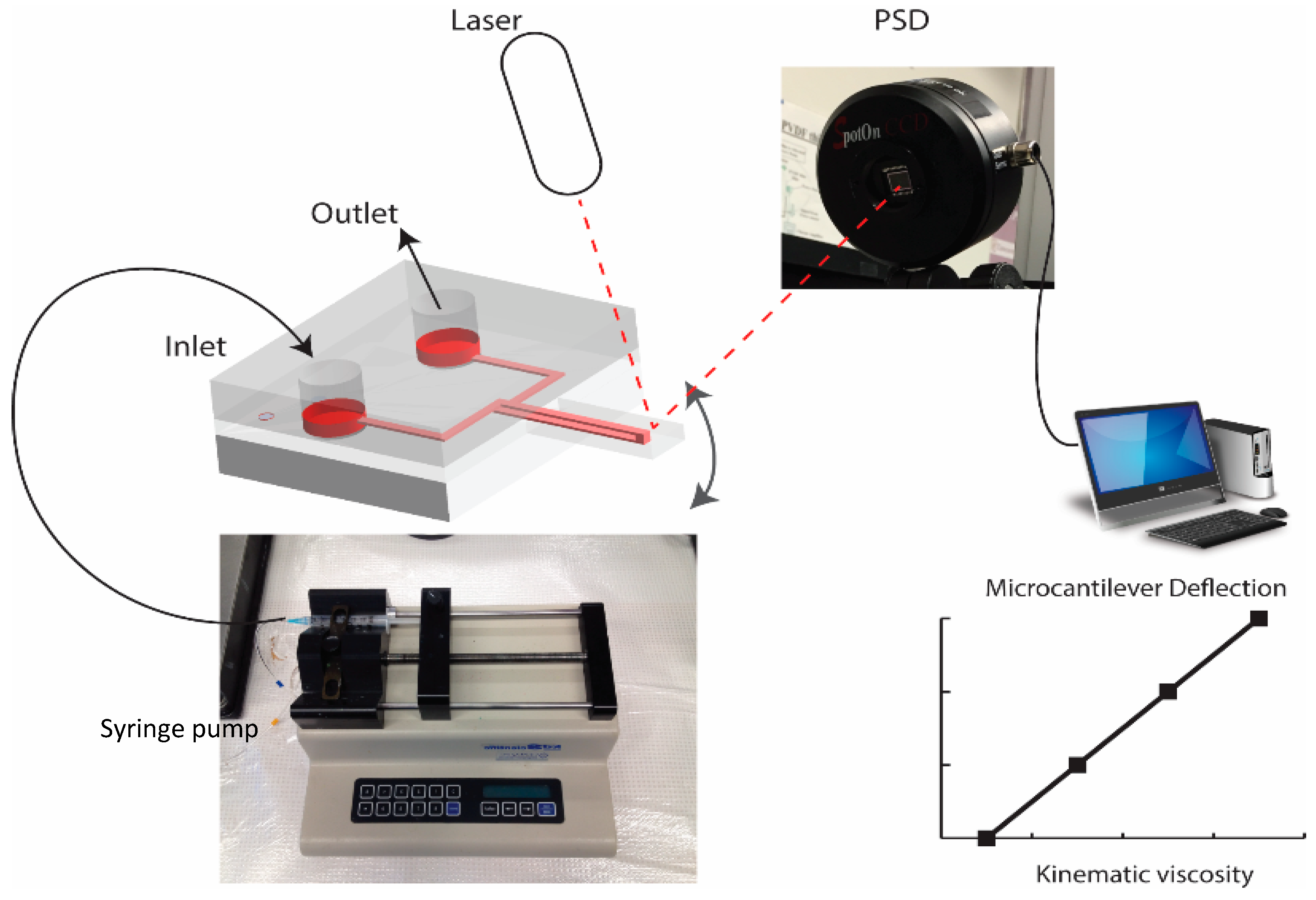
This section reports on an experiment which was performed to measure changes in fluid kinematic viscosity using the 3D polymeric suspended microfluidics. To modify kinematic viscosity of fluids in experiments, DI water with different concentrations of salt (NaCl), 0–15% as a solution, and milk with fat concentrations of 0–35% as a colloidal fluid were used. An optical laser deflection measurement system was used to detect microcantilever deflections against variations in fluid properties (Figure 4). The optical laser deflection measurement system works based on the reflection of a laser beam from the tip of the microcantilever. The light travel distance is read on a Photo Sensitive Detector (PSD), which can be calibrated with the cantilever tip deflection according to the measurement setup dimensions [37].
In this experiment, the salt-water and milk-fat solutions were injected into the SPMF3 using a syringe pump at a flow rate of 50 μL/min and the cantilever deflection was recorded. According to the salt-water solutions in Table 1, kinematic viscosity variations through the addition of salt could be detected by the SPMF3 using tip deflection. However, both density and viscosity increased when salt was added to the DI water. As such, Table 1 summarizes the microcantilever deflections against changes with fat contents of milk. Milk viscosity increased with fat concentration while its density decreased [38].
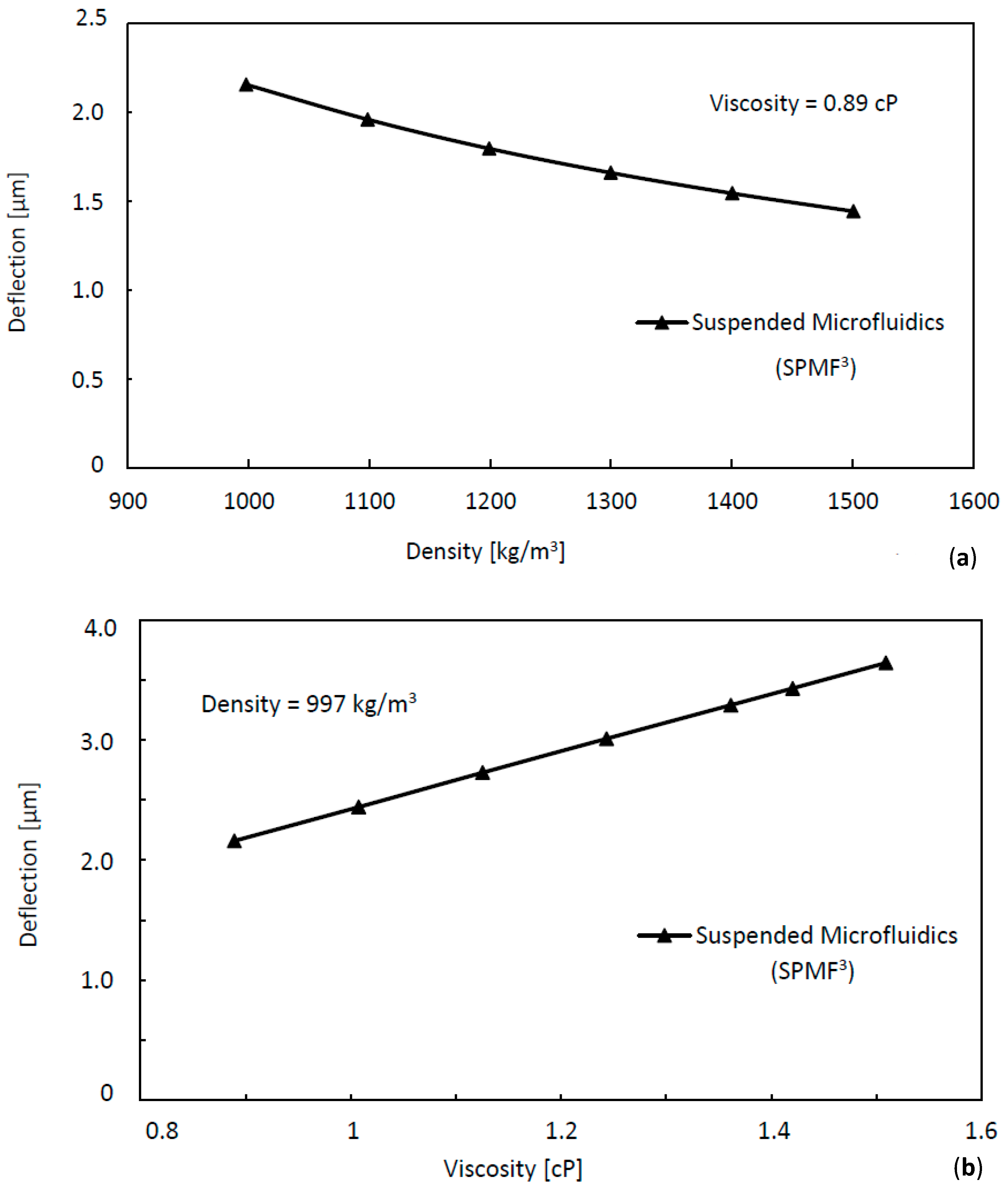
The source of tip deflection variations among different solutions could have been due to changes in either density or dynamic viscosity, or both. To further investigate the source of this change, a finite element analysis (FEA) was done with different fluid densities while the viscosity was kept identical and vice versa, and then the results were compared with the experimental data of Table 1. In this FEA modeling, a microcantilever with length, width and thickness of 6000 × 2000 × 600 μm, respectively, with an embedded microchannel of 200 × 100 μm was modeled. The flow rate was kept constant as 50 μL/min, equal to the mass flow rate of = 8.33 × 10⁻⁷ kg/s at ρ = 103 kg/m3, and the fluid was water. This analysis has been done using two ANSYS modules, namely CFX and Static (2017, ANSYS, Pittsburgh, PA, USA), to solve the Navier–Stockes equations of steady state fluid dynamics and structural behaviors in order to predict the resultant deflections due to applied flow forces on the microcantilever.
As given in Figure 5a,b, the predicted variations of deflection show that the microcantilever deflection decreases when density is increased at a constant viscosity, while its deflection increases when viscosity is increased at constant density. Since the flow rate was kept constant during experiments and prediction, increasing of density decreased the pressure difference, which led to lower velocity difference and hence the deflection which is also seen in Equations (5) and (6). On the other hand, when viscosity was increased, pressure difference increased, which resulted in higher cantilever deflection. Therefore, the FEA modeling also confirmed that both density and viscosity variations affect the SPMF3 deflections. However, the FEA results have confirmed that the viscosity and density effects are opposite to each other.
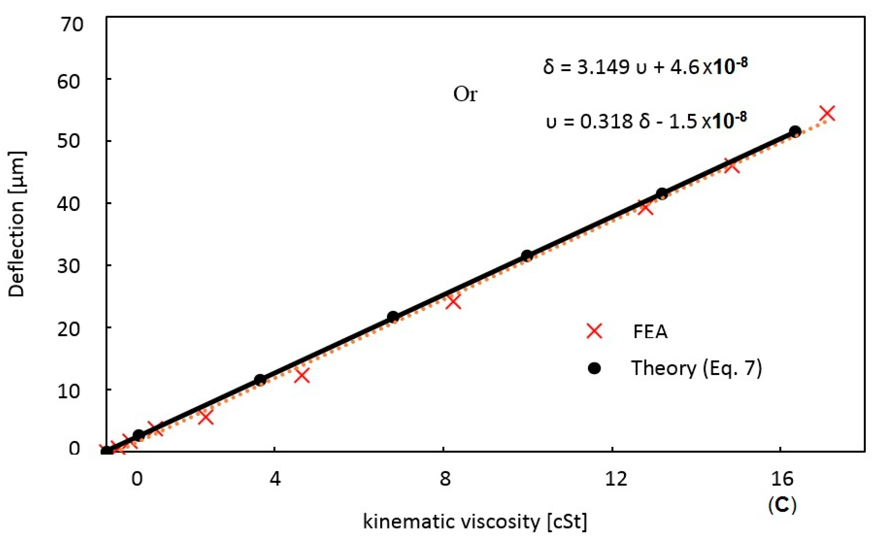
As explained earlier, viscosity and density are coupled in influencing the structural behavior and a comprehensive parameter would be helpful to capture their influence on microcantilever deflection. Hence, kinematic viscosity—which absorbs the combined effects of dynamic viscosity and density—is used to represent the fluid in order to capture the variation of dynamic viscosity and density.
To address this issue here, the simulation results are presented with kinematic viscosity (Figure 5c) over a wide range, covering possible engineering applications. This shows how these two parameters—dynamic viscosity and density—can represent the fluid property under study when coupled together as a single parameter. The kinematic viscosity range is chosen to represent a variety of fluids from simple Newtonian fluids, such as water, to non-Newtonian fluids, such as milk and blood. Using design parameters of the SPMF3, the theoretical prediction (Equation (7)) is compared with FEA results and shown in Figure 5c. These parameters are microchannel hydraulic diameter, (a = 133 μm), velocity difference at nozzle sides, ( = 0.002 m/s), microcantilever stiffness, ( = 0.035 N/m) which is calculated based on E = 700 kPa [34], mass flow rate, ( = 8.33 × 10⁻⁷ kg/s), and nozzle length, (l = 300 µm). The parameters are substituted into the derived theoretical formula which can be simplified as where k is the resultant cantilever stiffness. The theoretical formulation can be used to design any SPMF3 for required kinematic viscosity measurements. In other words, any variation in fluid concentration cannot exactly be predicted with only density or dynamic viscosity since both are changing and each parameter has a different effect on the static behavior of suspended microfluidics. The proposed suspended microcantilever has a unique response to changes in kinematic viscosity as is shown here, thus validating the SPMF3 as an appropriate tool for measuring fluid property through kinematic viscosity.
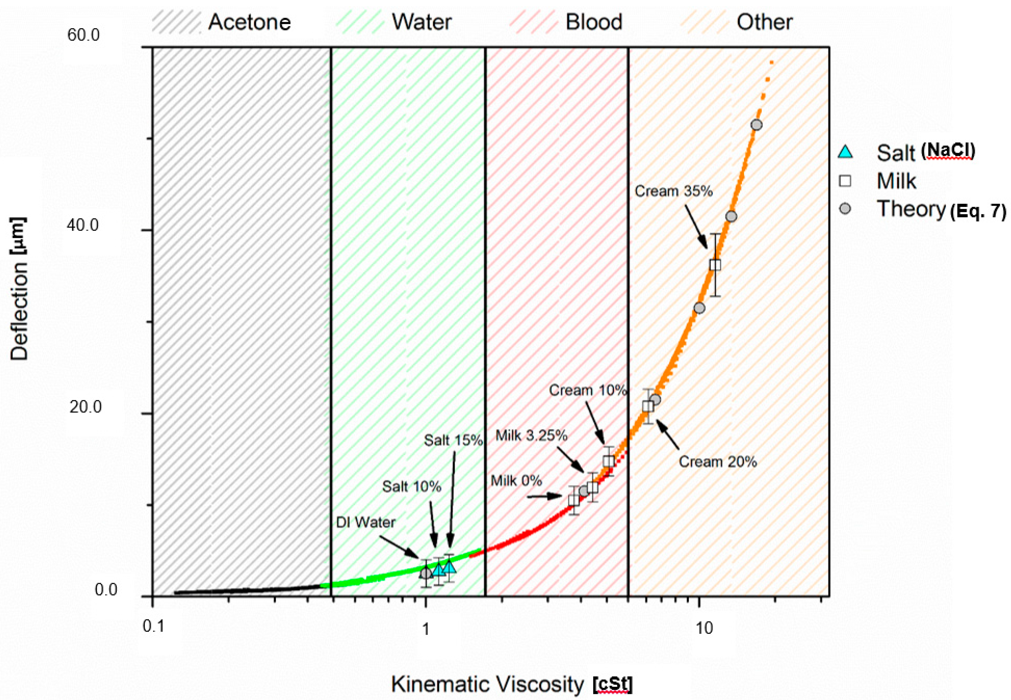
In a similar way, prediction has been continued for other fluids such as acetone, DI water, blood, milk and the results are presented against kinematic viscosity in Figure 6. These fluids were selected to basically cover a reasonable range of the fluids, representing both Newtonian and non-Newtonian fluids together. In order to validate the SPMF3 platform for kinematic viscosity measurements, the experimental results with water-salt solutions and milk, in Table 1, are compared with finite element analysis and simplified prediction formulation in Figure 6. As is shown here, there is a good agreement among the theoretical, finite element and experimental results. These results are shown in the logarithmic format in order to represent fluid properties in equally expanded regions. As is shown, kinematic viscosity can be employed for studying variation in fluid properties specifically in a more comprehensive way.
The error bars of experimental results were calculated according to the geometrical scheme of the laser deflection measurement system. There are three main sources of error—laser angle, Photo Sensitive Detector (PSD) angle and microcantilever position—that should be considered in this experiment. According to the geometrical calculations [37], variation in each of the abovementioned parameters may add an error to the final microcantilever deflection of up to 10% of the measured value.
In the former studies, fluids were mostly Newtonian. However, the interpretation of microcantilever deflection is difficult in the case of an unknown fluid where the changes in dynamic viscosity and density are unknown. Moreover, if the fluid is non-Newtonian or multi-phasic, interpretation of experimental results and changes in microsystem deflection will be unclear. This, as well as the formula in the previous section, clearly states how viscosity and density of fluids are related when it comes to detecting changes in a fluid through an external force or effect. Thus, the new SPMF3 which is designed for kinematic viscosity measurement addresses the interconnectivity of density and viscosity.
4. Conclusions
In this study, a practical use of kinematic viscosity is given as a comprehensive fluid parameter. In order to measure fluid parameters and avoid former viscometer issues such as the necessity of the density value during viscosity measurement, a 3D suspended microfluidics has been designed based on a capillary measurement system. Detailed FEA modeling of the SPMF3 shows different behaviors of a microcantilever against fluid density and dynamic viscosity variations. Using kinematic viscosity as a comprehensive parameter, both Newtonian and non-Newtonian fluids were studied and tested in a less complicated manner.
In order to validate the kinematic viscosity effects and importance, the 3D suspended polymeric microfluidics was developed along with theoretical and finite element analysis. Solutions of DI water and salt of different concentrations, and milk with a variety of fat contents were injected to the fabricated microchannel and the microcantilever deflections were measured according to variations in solution concentration. Then, the SPMF3 deflections against kinematic viscosity variations were studied.
Finally, with a comparison between theoretical and experimental results, it was confirmed that the kinematic viscosity is a unique parameter in fluids that can capture the influence of fluid properties on structural behavior. Furthermore, the proposed SPMF3 platform shows promising results as a microsystem for kinematic viscosity measurements for Newtonian and non-Newtonian fluids, and biological and non-biological fluids in a unique way.
Acknowledgments
The authors acknowledge research support from NSERC and Concordia Research Chair grants of M.P. and NSERC grant of J.D.
Author Contributions
M.P. conceived the study. M.M. conducted experiments and performed analysis. M.M. and M.P. wrote the manuscript. M.M., M.P. and J.D. participated in the preparation and editing of the manuscript.
Conflicts of Interest
The authors declare no conflict of interests.
References
- Trope, G.E.; Lowe, G.D.; McArdle, B.M.; Douglas, J.T.; Forbes, C.D.; Prentice, C.M.; Foulds, W.S. Abnormal blood viscosity and haemostasis in long-standing retinal vein occlusion. Br. J. Ophthalmol. 1983, 63, 137–142. [Google Scholar] [CrossRef]
- Cho, Y.; Kensey, K. Effects of the non-Newtonian viscosity of blood on flows in a diseased arterial vessel. Part 1: Steady flows. Biorheology 1991, 28, 241–262. [Google Scholar] [CrossRef] [PubMed]
- Cho, Y.; Hartnett, J.; Lee, W. Non-Newtonian viscosity measurements in the intermediate shear rate range with the falling-ball viscometer. J. Non-Newton. Fluid Mech. 1984, 15, 61–74. [Google Scholar] [CrossRef]
- Sader, J.E. frequency response of cantilever bemas immersed in viscous fluids with applications to the atomic force microscope. J. Appl. Phys. 1998, 84, 64–76. [Google Scholar] [CrossRef]
- Muramatsu, H.; Tamiya, E.; Karube, I. Computation of equivalent circuit parameters of quartz crystals in contact with liquids and study of liquid properties. Anal. Chem. 1988, 60, 2142–2146. [Google Scholar] [CrossRef]
- Angelescu, D.; Chen, H.; Jundt, J.; Berthet, H.; Mercier, B.; Marty, F. Highly integrated microfluidic sensors. In Proceedings of the SPIE, San Diego, CA, USA, 10–14 August 2008. [Google Scholar]
- Jakoby, B.; Scherer, M.; Buskies, M.; Eisenschmid, H. An automotive engine oil viscosity sensor. IEEE Sens. J. 2003, 3, 562–568. [Google Scholar] [CrossRef]
- Matsiev, L. Application of flexural mechanical resonators to high throughput liquid characterization. In Proceedings of the 2000 IEEE Ultrasonics Symposium, San Juan, Puerto Rico, 22–25 October 2000. [Google Scholar]
- Wang, S. Engine oil condition sensor: Method for establishing correlation with total acid number. Sens. Actuators B Chem. 2002, 86, 122–126. [Google Scholar] [CrossRef]
- Goubaidoulline, I.; Reuber, J.; Merz, F.; Johannsmann, D. Simultaneous determination of density and viscosity of liquids based on quartz crystal resonators covered with nanoporous alumina. J. Appl. Phys. 2005, 98, 014305. [Google Scholar] [CrossRef]
- Herrmann, F.; Hahn, D.; Buttgenback, S. Separate determination of liquid density and viscosity with sagittally corrugated Love-mode sensors. Sens. Actuators A Phys. 1999, 78, 99–107. [Google Scholar] [CrossRef]
- Durdag, K. Solid state acoustic wave sensors for real-time in-line measurement of oil viscosity. Sens. Rev. 2008, 28, 68–73. [Google Scholar] [CrossRef]
- Martin, B. Viscosity and density sensing with ultrasonic plate waves. Sens. Actuators A Phys. 1990, 22, 704–708. [Google Scholar] [CrossRef]
- Wenzel, S.; Martin, B.; White, R. Generalized Lamb-wave multisensory. In Proceedings of the IEEE Ultrasonics Symposium, Chicago, IL, USA, 2–5 October 1988. [Google Scholar]
- Wolf, S.; Tauber, R. Silicon Processing for the VLSI Era; Lattice Press: Sunset Beach, CA, USA, 1986. [Google Scholar]
- Puchades, I.; Fuller, L.F. A Thermally Actuated Microelectromechanical (MEMS) Device for Measuring Viscosity. J. Microelectromech. Syst. 2011, 20, 601–609. [Google Scholar] [CrossRef]
- Boss, C.; Meurville, E.; Sallese, J.-M.; Ryser, P. A viscosity-dependent affinity sensor for continuous monitoring of glucose in biological fluids. Biosens. Bioelectron. 2011, 30, 223–228. [Google Scholar] [CrossRef] [PubMed]
- Muramatsu, H.; Kimura, K.; Ataka, T. A quartz crystal viscosity sensor for monitoring coagulation reaction and its application to a multichannel coagulation detector. Biosens. Bioelectron. 1991, 6, 353–358. [Google Scholar] [CrossRef]
- Shih, W.; Li, X.; Gu, H.; Shih, W.; Aksay, I.A. Simultaneous liquid viscosity and density determination with piezoelectric unimorph cantilevers. J. Appl. Phys. 2001, 89, 1497. [Google Scholar] [CrossRef]
- Naik, T.; Longmire, E.; Mantell, S. Dynamic response of a cantilever in liquid near a solid wall. Sens. Actuators 2003, 102, 240–245. [Google Scholar] [CrossRef]
- Rezazadeh, G.; Ghanbari, M.; Mirzaee, I. Simultaneous Measurement of Fluids viscosity and density using a microbeam. In Proceedings of the International Conference on Perspective Technologies and Methods in MEMS Design, Lviv-Polyana, Ukraine, 22–24 April 2009. [Google Scholar]
- Huang, X.; Li, S.; Schultz, J.; Wang, Q.; Lin, Q. Mems sensor for continuous monitoring of glucose in Subcutaneous Tissue. In Proceedings of the IEEE 22nd International Conference on Micro Electro Mechanical Systems, Sorrento, Italy, 25–29 January 2009. [Google Scholar]
- Belmiloud, N.; Dufour, I.; Nicu, L.; Colin, A.; Pistre, J. Vibrating Microcantilever used as a viscometer and microrheometer. In Proceedings of the IEEE Sensors, Daegu, Korea, 22–25 October 2006. [Google Scholar]
- Harrison, C.; Fornari, A.; Hua, C.; Ryu, S.; Goodwin, A.R.; Hsu, K.; Marty, F.; Mercier, B. A microfluidic MEMS sensor for the measurement of density and viscosity at high pressure. In Proceedings of the SPIE, San Jose, CA, USA, 29 January–1 February 2007; Volume 6465, p. 64650U. [Google Scholar]
- Reichel, E.; Riesch, C.; Keplinger, F.; Jakoby, B.; Microelectronics, I.; Kepler, J. Remote electromagnetic excitation of miniaturized in-plane plate resonators for sensing applications. In Proceedings of the IEEE International Frequency Control Symposium, Honolulu, HI, USA, 19–21 May 2008. [Google Scholar]
- Ronaldson, K.A.; Fitt, A.D.; Goodwin, A.R.H.; Wakeham, W.A. Transversely Oscillating MEMS Viscometer: The “Spider”. Int. J. Thermophys. 2006, 27, 1677–1695. [Google Scholar] [CrossRef]
- Agoston, A.; Keplinger, F.; Jakoby, B. Evaluation of a Vibrating Micromachined Cantilever Sensor for Measuring the Viscosity of Complex Organic Liquids. Sens. Actuators A 2005, 123, 82–86. [Google Scholar] [CrossRef]
- Galambos, P.; Forster, F. An optical micro-fluidic viscometer. In Proceedings of the Micro-Electro-Mechanical Systems (MEMS), ASME International Mechanical Engineering Congress and Exposition, New York, NY, USA, 15–20 November 1998. [Google Scholar]
- Andrews, M.; Harris, P. Damping and gas viscosity measurements using a microstructure. Sens. Actuators A Phys. 1995, 49, 103–108. [Google Scholar] [CrossRef]
- Lara, M.M.; Atkinson, C. Theoretical model on the interaction of a vibrating beam and the surrounding viscous fluid with applications to density and viscosity sensors. In Proceedings of the IEEE Sensors, Vienna, Austria, 24–27 October 2004. [Google Scholar]
- Zeng, H.; Zhao, Y. On-Chip Blood Viscometer towards Point-of-Care Hematological Diagnosis. In Proceedings of the IEEE 22nd International Conference on Micro Electro Mechanical Systems, Sorrento, Italy, 25–29 January 2009. [Google Scholar]
- Dinsdale, A.; Moore, F. Viscosity and Its Measurement; Chapman and Hall: London, UK, 1962. [Google Scholar]
- Viswanath, D.S.; Ghosh, T.K.; Prasad, D.H.L.; Dutt, N.K.; Rani, K.Y. Viscosity of Liquids, Theory, Estimation, Experiment, and Data; Springer: Berlin, Germany, 2007. [Google Scholar]
- Sadabadi, H. Nano-integrated Polymeric Suspended Microfluidic Platform for Ultra-Sensitive Bio-Molecular Recognition. Ph.D. Thesis, Concordia University, Montreal, QC, Canada, 2013. [Google Scholar]
- Burg, T.P.; Godin, M.; Knudsen, S.M.; Shen, W.; Carlson, G.; Foster, J.S.; Babcock, K.; Manalis, S.R. Weighing of biomolecules, single cells and single nanoparticles in fluid. Nature 2007, 446, 1066–1069. [Google Scholar] [CrossRef] [PubMed]
- Sadabadi, H.; Packirisamy, M. Nano-integrated Polymeric Suspended Microfluidic (SPMF) Platform for Ultra-Sensitive Bio-Molecular Recognition of Bovine Growth Hormones. Sci. Rep. 2017, 7, 10969. [Google Scholar] [CrossRef] [PubMed]
- Beaulieua, L.; Godin, M.; Laroche, O.; Tabard-Cossa, V.; Grutter, P. A complete analysis of the laser beam deflection systems used in cantilever-based systems. Ultramicroscopy 2007, 107, 422–430. [Google Scholar] [CrossRef] [PubMed]
- Vliet, T.V.; Walstra, P. Relationship between viscosity and fat content of milk and cream. Texture Stud. 1980, 11, 65–68. [Google Scholar] [CrossRef]
Figure 1.
(a) Capillary kinematic viscosity measurement system, (b) Microfluidic system designed based on the capillary system, (c) Suspended microchannel designed to transduce and measure fluid forces.
Figure 1.
(a) Capillary kinematic viscosity measurement system, (b) Microfluidic system designed based on the capillary system, (c) Suspended microchannel designed to transduce and measure fluid forces.
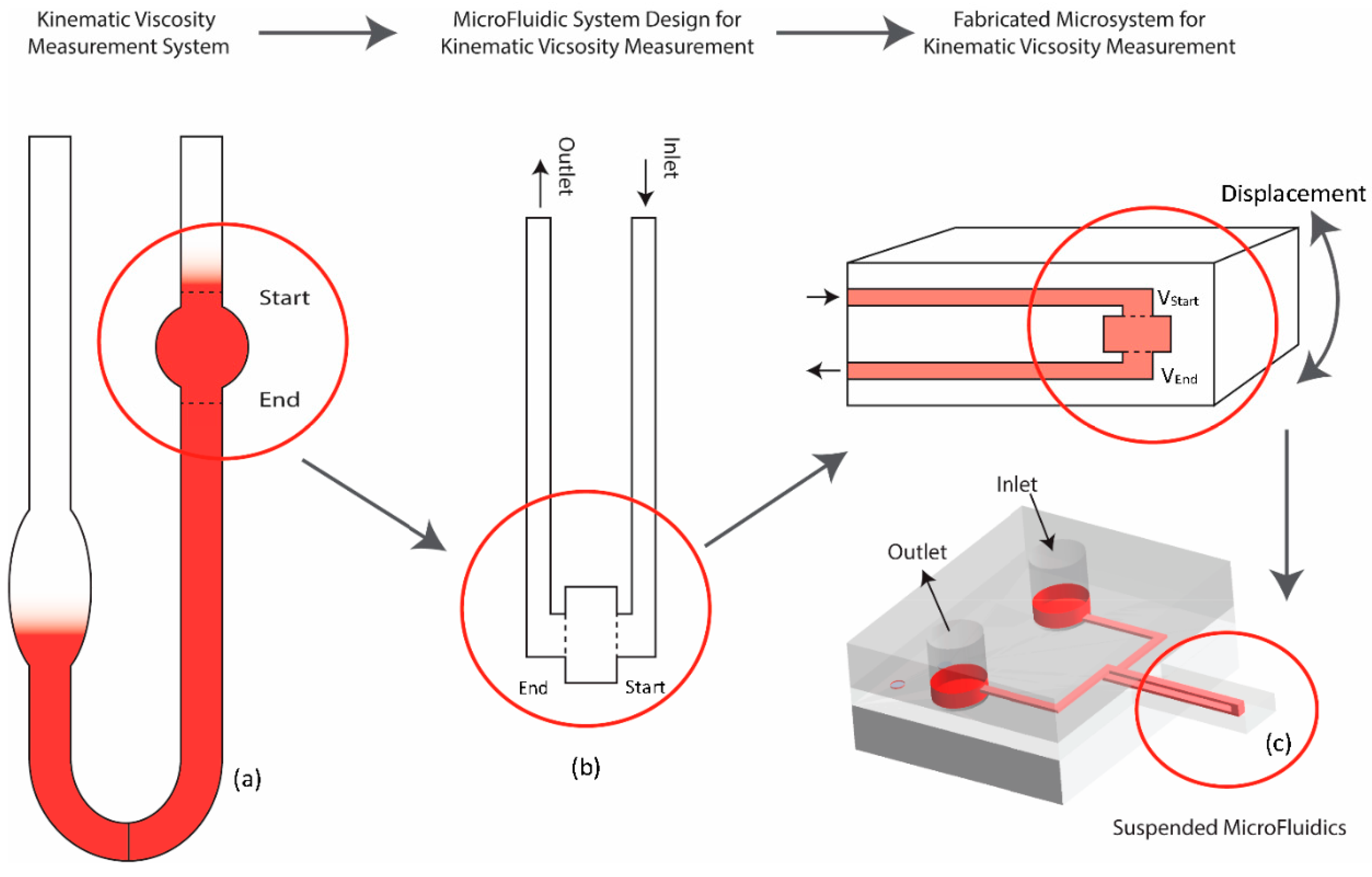
Figure 2.
(a) 2D suspended microfluidics with the flow plane parallel to the bending (neutral) plane, (b) 3D suspended polymeric microfluidics with the flow plane orthogonal to the bending plane.
Figure 2.
(a) 2D suspended microfluidics with the flow plane parallel to the bending (neutral) plane, (b) 3D suspended polymeric microfluidics with the flow plane orthogonal to the bending plane.
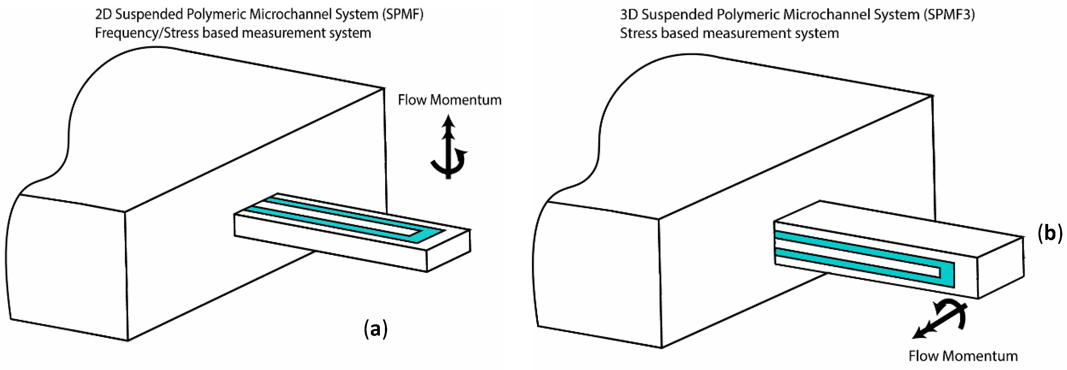
Figure 3.
(a) Microchannel and nozzle molds for PDMS microfabrication, (b) Fabricated 3D suspended polymeric microfluidic system (c) Detailed view of the SPMF3.
Figure 3.
(a) Microchannel and nozzle molds for PDMS microfabrication, (b) Fabricated 3D suspended polymeric microfluidic system (c) Detailed view of the SPMF3.
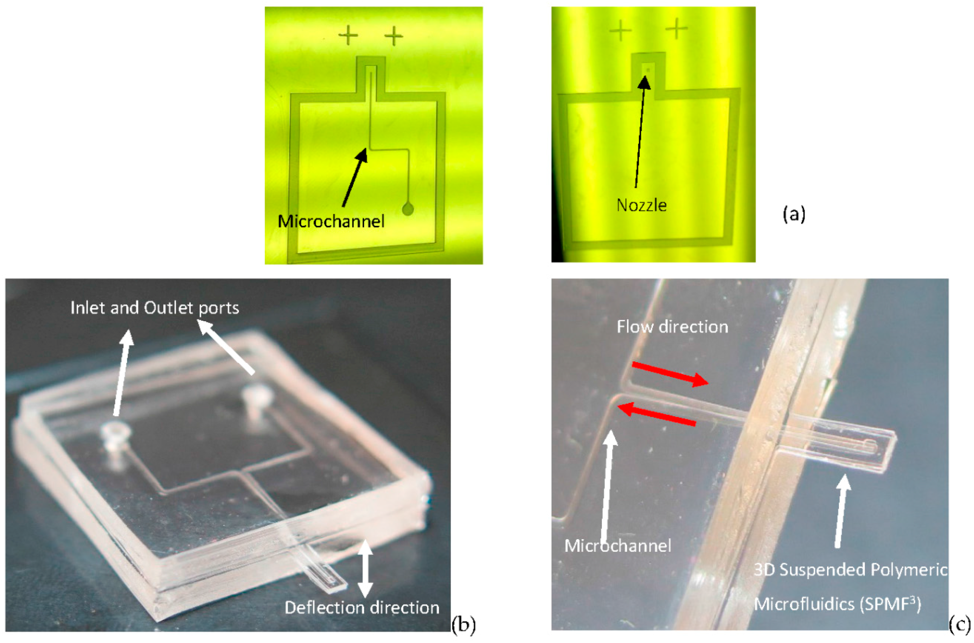
Figure 4.
Laser displacement measurement system.

Figure 5.
Finite element analysis results of microcantilever deflection when fluid density or viscosity was changed, (a) against density at constant viscosity, μ = 0.89 cP, (b) against viscosity at constant density, ρ = 997 kg/m3, (c) finite element analysis (FEA) and theoretical results of microcantilever deflection against kinematic viscosity.


Figure 6.
Prediction and experiment comparison of deflection behavior for various fluids; different ranges of fluids are indicated with colorful hatching and the cantilever deflection is shown with colorful dots.
Figure 6.
Prediction and experiment comparison of deflection behavior for various fluids; different ranges of fluids are indicated with colorful hatching and the cantilever deflection is shown with colorful dots.

Table 1.
Changes in DI water-salt solution and milk with different fat content properties and experimental deflection results; both density and viscosity varied with salt and fat concentrations.
Table 1.
Changes in DI water-salt solution and milk with different fat content properties and experimental deflection results; both density and viscosity varied with salt and fat concentrations.
| Fluid | Concentration | Density (kg/m3) | Dynamic Viscosity (cP) | Kinematic Viscosity (cSt) | Tip Deflection (μm) |
|---|---|---|---|---|---|
| Water-Salt wt % | 0% | 999 | 1.002 | 1.00 | 2.51 |
| 10% | 1070 | 1.193 | 1.11 | 2.75 | |
| 15% | 1110 | 1.350 | 1.21 | 3.08 | |
| Milk-Fat wt % | 0% | 1033 | 3.594 | 3.48 | 10.48 |
| 3.25% | 1030 | 4.192 | 4.07 | 11.90 | |
| 10% | 1025 | 4.797 | 4.68 | 14.85 | |
| 20% | 1012 | 6.598 | 6.52 | 20.80 | |
| 35% | 994 | 11.391 | 11.46 | 36.21 |
© 2017 by the authors. Licensee MDPI, Basel, Switzerland. This article is an open access article distributed under the terms and conditions of the Creative Commons Attribution (CC BY) license (http://creativecommons.org/licenses/by/4.0/).
Share and Cite
MDPI and ACS Style
Marzban, M.; Packirisamy, M.; Dargahi, J. 3D Suspended Polymeric Microfluidics (SPMF3) with Flow Orthogonal to Bending (FOB) for Fluid Analysis through Kinematic Viscosity. Appl. Sci. 2017, 7, 1048. https://doi.org/10.3390/app7101048
AMA Style
Marzban M, Packirisamy M, Dargahi J. 3D Suspended Polymeric Microfluidics (SPMF3) with Flow Orthogonal to Bending (FOB) for Fluid Analysis through Kinematic Viscosity. Applied Sciences. 2017; 7(10):1048. https://doi.org/10.3390/app7101048
Chicago/Turabian StyleMarzban, Mostapha, Muthukumaran Packirisamy, and Javad Dargahi. 2017. "3D Suspended Polymeric Microfluidics (SPMF3) with Flow Orthogonal to Bending (FOB) for Fluid Analysis through Kinematic Viscosity" Applied Sciences 7, no. 10: 1048. https://doi.org/10.3390/app7101048
Note that from the first issue of 2016, this journal uses article numbers instead of page numbers. See further details here.